

Research on Hybrid Force Control of Redundant Manipulator with Reverse Task Priority

 ,
,
Abstract
:1. Introduction
- (1)
- The implementation of hierarchical force control in the Cartesian space.
- (2)
- The algorithmic singularities can be reduced.
- (3)
- The manipulator–environment interaction can be guaranteed.
2. Preliminaries
2.1. Jacobian-Based Solution
2.2. The Task-Priority-Based Solution
2.3. Singularity-Robust Solution
3. Reverse Priority Control of Manipulator
3.1. Reverse Priority Control of Redundant Manipulator with Multiple Tasks
3.2. Reverse Priority Control of Redundant Manipulator with Two Tasks
4. Reverse Priority Impedance Control
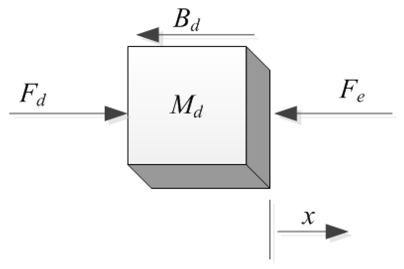
4.1. The Reverse Priority Force Control of Manipulator
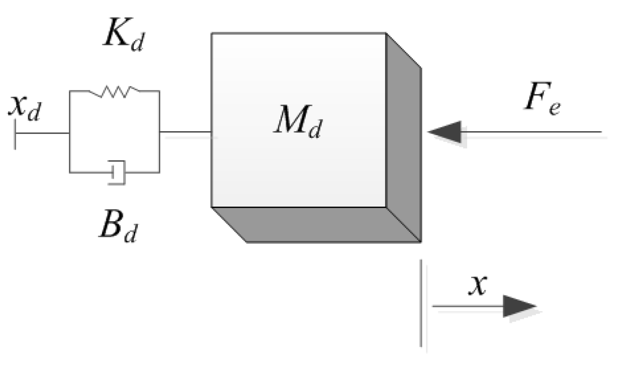
4.2. The Reverse Priority Impedance Control of Manipulator
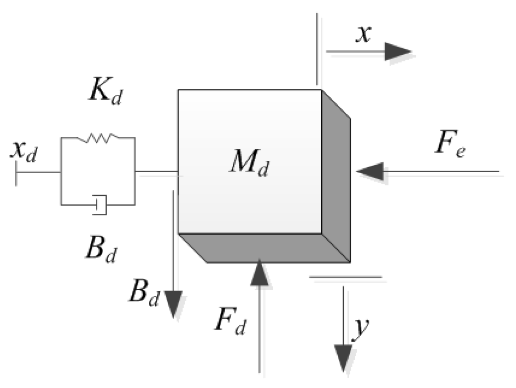
4.3. The Reverse Priority Hybrid Impedance Control of Manipulator
5. Simulation
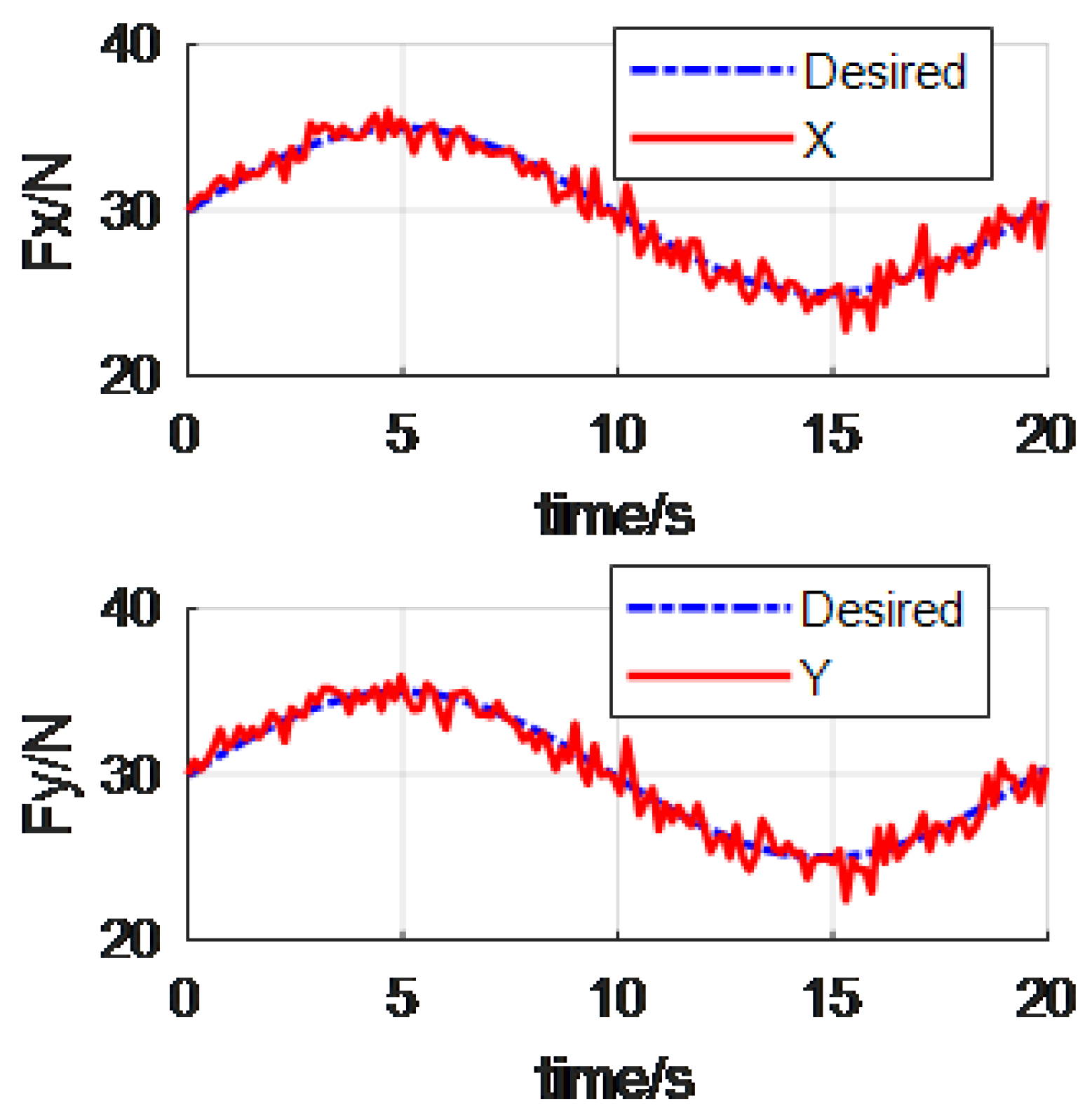
5.1. Example 1
5.2. Example 2
6. Conclusions
Author Contributions
Funding
Institutional Review Board Statement
Informed Consent Statement
Data Availability Statement
Conflicts of Interest
Abbreviations
| DOFs | degrees of freedom |
| DLS | the damped least squares |
| SVD | the singular value decomposition |
| DH parameters | Denavit–Hartenberg parameters |
| PID controller | Proportional Integral Derivative controller |
References
- Dou, R.; Yu, S.; Li, W.; Chen, P.; Xia, P.; Zhai, F.; Yokoib, H.; Jiang, Y. Inverse kinematics for a 7-DOF humanoid robotic arm with joint limit and end pose coupling. Mech. Mach. Theory 2022, 169, 104637. [Google Scholar] [CrossRef]
- Schreiber, L.; Gosselin, C. Determination of the Inverse Kinematics Branches of Solution Based on Joint Coordinates for Universal Robots-Like Serial Robot Architecture. J. Mech. Robot. Trans. ASME 2022, 14, 034501. [Google Scholar] [CrossRef]
- Kim, J.; Jie, W.; Kim, H.; Lee, M.C. Modified Configuration Control with Potential Field for Inverse Kinematic Solution of Redundant Manipulator. IEEE/ASME Trans. Mechatron. 2021, 26, 1782–1790. [Google Scholar] [CrossRef]
- Chen, D.; Zhang, Y.; Li, S. Tracking control of robot manipulators with unknown models: A Jacobian-matrix-adaption method. IEEE Trans. Ind. Inform. 2018, 14, 3044–3053. [Google Scholar] [CrossRef]
- Zhang, Y.; Li, S.; Kadry, S.; Liao, B. Recurrent Neural Network for Kinematic Control of Redundant Manipulators with Periodic Input Disturbance and Physical Constraints. IEEE Trans. Cybern. 2018, 99, 4194–4205. [Google Scholar] [CrossRef] [PubMed]
- Faroni, M.; Beschi, M.; Pedrocchi, N.; Visioli, A. Predictive Inverse Kinematics for Redundant Manipulators with Task Scaling and Kinematic Constraints. IEEE Trans. Robot. 2019, 35, 278–285. [Google Scholar] [CrossRef]
- Ruiz, A.G.; Santos, J.C.; Croes, J.; Desmet, W.; da Silva, M.M. On redundancy resolution and energy consumption of kinematically redundant planar parallel manipulators. Robot. Int. J. Inf. Educ. Res. Robot. Artif. Intell. 2018, 36, 809–821. [Google Scholar] [CrossRef]
- Zhang, Y.; Chen, S.; Li, S.; Zhang, Z. Adaptive projection neural network for kinematic control of redundant manipulators with unknown physical parameters. IEEE Trans. Ind. Electron. 2018, 65, 4909–4920. [Google Scholar] [CrossRef]
- Nakamura, Y.; Hanafusa, H.; Yoshikawa, T. Task-priority based redundancy control of robot manipulators. Int. J. Robot. Res. 1987, 6, 3–15. [Google Scholar] [CrossRef]
- Baerlocher, P.; Boulic, R. Task-priority formulations for the kinematic control of highly redundant articulated structures. In Proceedings of the IEEE/RSJ International Conference on Intelligent Robots and Systems (IROS), Victoria, BC, Canada, 17 October 1998. [Google Scholar]
- Kanoun, O.; Lamiraux, F.; Wieber, P.B. Kinematic control of redundant manipulators: Generalizing the task priority framework to inequality tasks. IEEE Trans. Robot. 2011, 27, 785–792. [Google Scholar] [CrossRef] [Green Version]
- Simetti, E.; Casalino, G.; Wanderlingh, F.; Aicardi, M. A task priority approach to cooperative mobile manipulation: Theory and experiments. Robot Auton Syst. 2019, 122, 103287. [Google Scholar] [CrossRef]
- Fu, L.; Zhao, J. Maxwell Model-Based Null Space Compliance Control in the Task-Priority Framework for Redundant Manipulators. IEEE Access 2020, 8, 35892–35904. [Google Scholar] [CrossRef]
- Peng, G.; Yang, C.; He, W.; Chen, C.P. Force sensorless admittancecontrol with neural learning for robots with actuator saturation. IEEE Trans. Ind. Electron. 2020, 67, 3138–3148. [Google Scholar] [CrossRef]
- Chiaverini, S. Singularity-robust task-priority redundancy resolution for real-time kinematic control of robot manipulators. IEEE Trans. Robot. Autom. 1997, 13, 398–410. [Google Scholar] [CrossRef]
- Antonelli, G. Stability analysis for prioritized closed-loop inverse kinematic algorithms for redundant robotic systems. IEEE Trans. Robot. 2009, 25, 985–994. [Google Scholar] [CrossRef]
- Simetti, E.; Casalino, G. Whole body control of a dual arm underwater vehicle manipulator system. Annu. Rev. Control 2015, 40, 191–200. [Google Scholar] [CrossRef]
- Simetti, E.; Casalino, G. A novel practical technique to integrate inequality control objectives and task transitions in priority based control. J. Intell. Robot. Syst. 2016, 84, 877–902. [Google Scholar] [CrossRef]
- Flacco, F.; De Luca, A. A reverse priority approach to multi-task control of redundant robots. In Proceedings of the IEEE/RSJ International Conference on Intelligent Robots and Systems (IROS), Chicago, IL, USA, 14–18 September 2014; pp. 2421–2427. [Google Scholar]
- Flacco, F.; De Luca, A. Unilateral constraints in the reverse priority redundancy resolution method. In Proceedings of the IEEE/RSJ International Conference on Intelligent Robots and Systems (IROS), Hamburg, Germany, 28 September–2 October 2015; pp. 2564–2571. [Google Scholar]
- Hogan, N. Stable execution of contact tasks using impedance control. In Proceedings of the IEEE International Conference on Robotics and Automation, Raleigh, NC, USA, 31 March–3 April 1987; pp. 1047–1054. [Google Scholar]
- Albu-Schäffer, A.; Ott, C.; Hirzinger, G. A unified passivity-based control framework for position, torque and impedance control of flexible joint robots. Int. J. Robot. Res. 2007, 26, 23–39. [Google Scholar] [CrossRef]
- Hogan, N. Impedance control: An approach to manipulation: Part II—Implementation. J. Dyn. Syst. Meas. Control. 1985, 107, 8–16. [Google Scholar] [CrossRef]
- Anderson, R.J.; Spong, M.W. Hybrid impedance control of robotic manipulators. IEEE J. Robot. Autom. 1988, 4, 549–556. [Google Scholar] [CrossRef]
- Kumar, S.; Rastogi, V.; Gupta, P. A hybrid impedance control scheme for underwater welding robots with a passive foundation in the controller domain. Simul. Trans. Soc. Model. Simul. Int. 2017, 93, 619–630. [Google Scholar] [CrossRef]
- Heinrichs, B.; Sepehri, N.; Thornton-Trump, A.B. Position-based impedance control of an industrial hydraulic manipulator. IEEE Control Syst. 1997, 17, 46–52. [Google Scholar]
- Focchi, M.; Medrano-Cerda, G.A.; Boaventura, T.; Frigerio, M.; Semini, C.; Buchli, J.; Caldwell, D.G. Robot impedance control and passivity analysis with inner torque and velocity feedback loops. Control Theory Technol. 2016, 14, 97–112. [Google Scholar] [CrossRef]
- Koivumäki, J.; Mattila, J. Stability-guaranteed impedance control of hydraulic robotic manipulators. IEEE/ASME Trans. Mechatron. 2017, 22, 601–612. [Google Scholar] [CrossRef]
- Bussmann, K.; Dietrich, A.; Ott, C. Whole-Body Impedance Control for a Planetary Rover with Robotic Arm: Theory, Control Design, and Experimental Validation. In Proceedings of the IEEE International Conference on Robotics and Automation (ICRA), Bribane, Australia, 21–25 May 2018; pp. 910–917. [Google Scholar]
- Souzanchi-K, M.; Arab, A.; Akbarzadeh-T, M.R.; Fateh, M.M. Robust Impedance Control of Uncertain Mobile Manipulators Using Time-Delay Compensation. IEEE Trans. Control. Syst. Technol. 2017, 26, 1942–1953. [Google Scholar] [CrossRef]
- Izadbakhsh, A.; Khorashadizadeh, S. Robust impedance control of robot manipulators using differential equations as universal approximator. Int. J. Control. 2018, 91, 2170–2186. [Google Scholar] [CrossRef]
- Adhikary, N.; Mahanta, C. Hybrid impedance control of robotic manipulator using adaptive backstepping sliding mode controller with pid sliding surface. In Proceedings of the Indian Control Conference (ICC), Guwahati, India, 4–6 January 2017; pp. 391–396. [Google Scholar]
- Sciavicco, L.; Siciliano, B. Modeling and Control of Robot Manipulators; Springer: London, UK, 2000. [Google Scholar]
- Trutman, P.; El Din, M.S.; Henrion, D.; Pajdla, T. Globally Optimal Solution to Inverse Kinematics of 7DOF Serial Manipulator. IEEE Robot. Autom. Lett. 2022, 7, 6012–6019. [Google Scholar] [CrossRef]
- Dietrich, A.; Ott, C.; Albu-Schäffer, A. An overview of null space projections for redundant, torque-controlled robots. Int. J. Robot. Res. 2015, 34, 1385–1400. [Google Scholar] [CrossRef] [Green Version]
- Hu, Y.; Huang, B.; Yang, G.Z. Task-priority redundancy resolution for co-operative control under task conflicts and joint constraints. In Proceedings of the 2015 IEEE/RSJ International Conference on Intelligent Robots and Systems (IROS), Hamburg, Germany, 28 September–2 October 2015; pp. 2398–2405. [Google Scholar]


| d | a | alpha | qlim | |
|---|---|---|---|---|
| Link1 | 0.317 | −0.081 | −pi/2 | [−pi,pi] |
| Link2 | −0.1925 | 0 | pi/2 | [−pi,pi] |
| Link3 | 0.4 | 0 | −pi/2 | [−pi,pi] |
| Link4 | −0.1685 | 0 | pi/2 | [−pi,pi] |
| Link5 | 0.4 | 0 | −pi/2 | [−pi,pi] |
| Link6 | −0.1363 | 0 | pi/2 | [−pi,pi] |
| Link7 | 0.13375 | 0 | pi/2 | [−pi,pi] |
Publisher’s Note: MDPI stays neutral with regard to jurisdictional claims in published maps and institutional affiliations. |
© 2022 by the authors. Licensee MDPI, Basel, Switzerland. This article is an open access article distributed under the terms and conditions of the Creative Commons Attribution (CC BY) license (https://creativecommons.org/licenses/by/4.0/).
Share and Cite
Su, Y.; Liu, H.; Li, Y.; Xue, B.; Liu, X.; Li, M.; Lin, C.; Wu, X. Research on Hybrid Force Control of Redundant Manipulator with Reverse Task Priority. Materials 2022, 15, 6611. https://doi.org/10.3390/ma15196611
Su Y, Liu H, Li Y, Xue B, Liu X, Li M, Lin C, Wu X. Research on Hybrid Force Control of Redundant Manipulator with Reverse Task Priority. Materials. 2022; 15(19):6611. https://doi.org/10.3390/ma15196611
Chicago/Turabian StyleSu, Yu, Haiyan Liu, You Li, Bin Xue, Xianqing Liu, Minsi Li, Chunlan Lin, and Xueying Wu. 2022. "Research on Hybrid Force Control of Redundant Manipulator with Reverse Task Priority" Materials 15, no. 19: 6611. https://doi.org/10.3390/ma15196611