
Nanomechanics of Retained Austenite in Medium-Carbon Low-Temperature Bainitic Steel: A Critical Analysis of a One-Step versus a Two-Step Treatment
 ,
,
Abstract
:1. Introduction
2. Experimental Procedures
3. Results
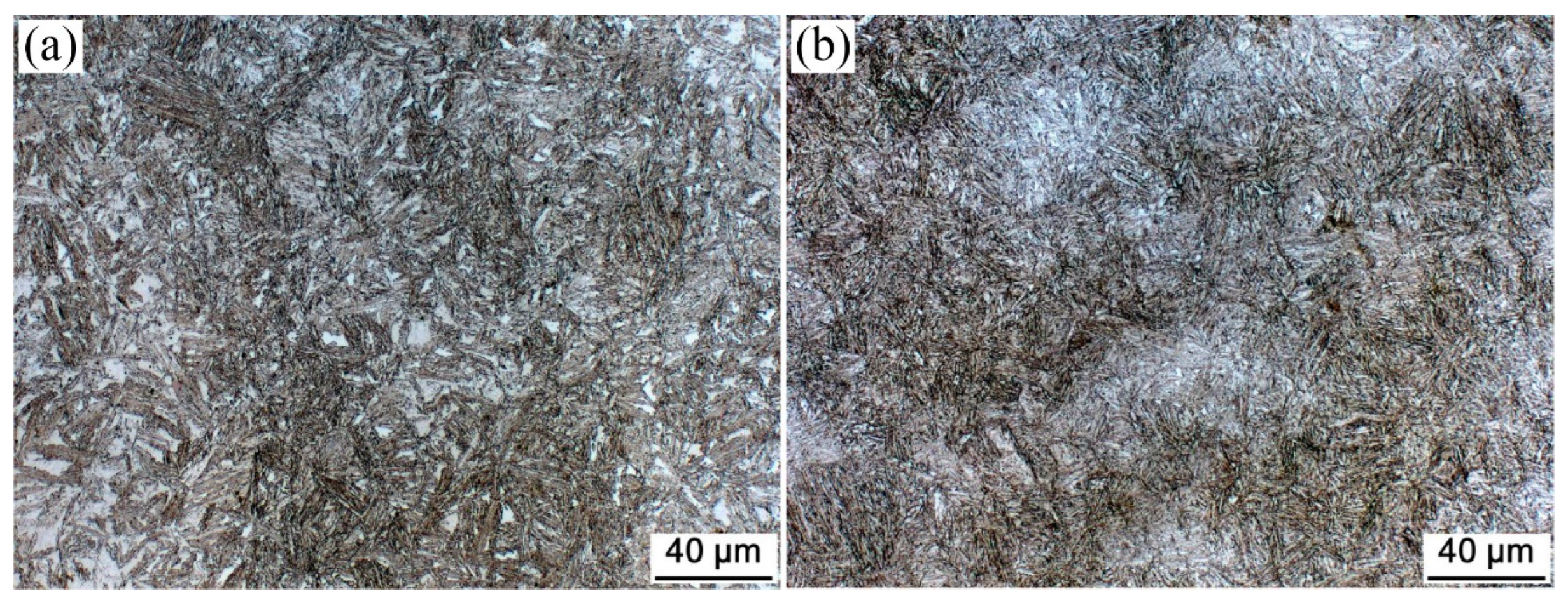
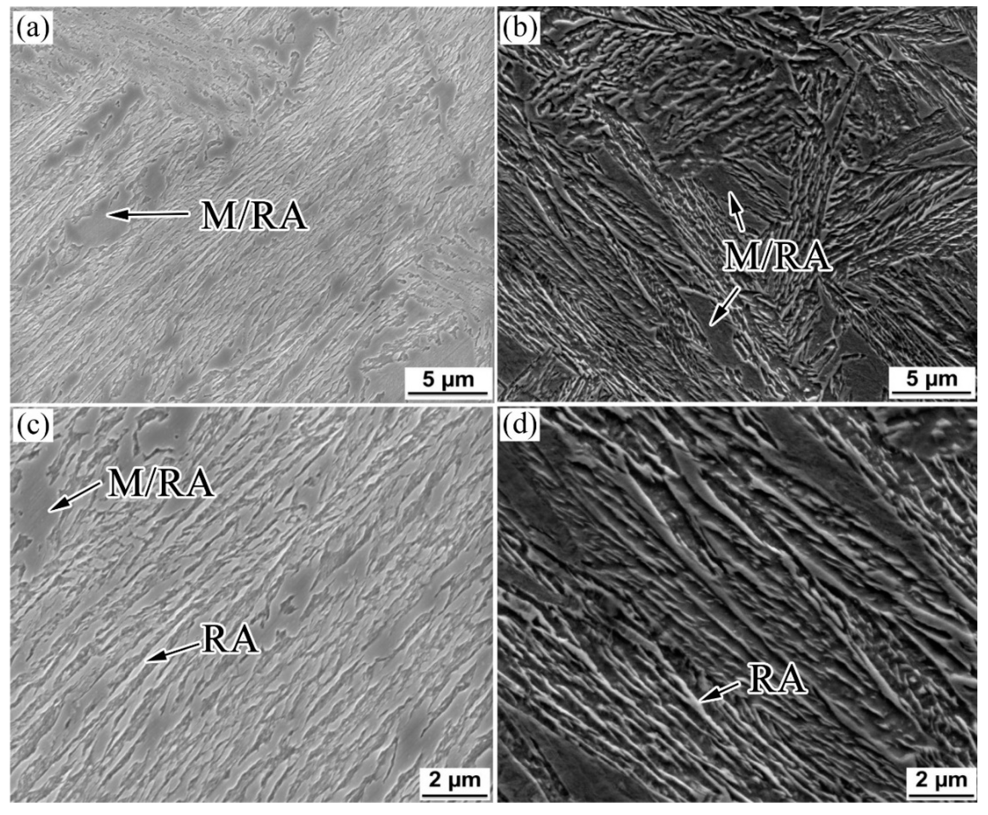
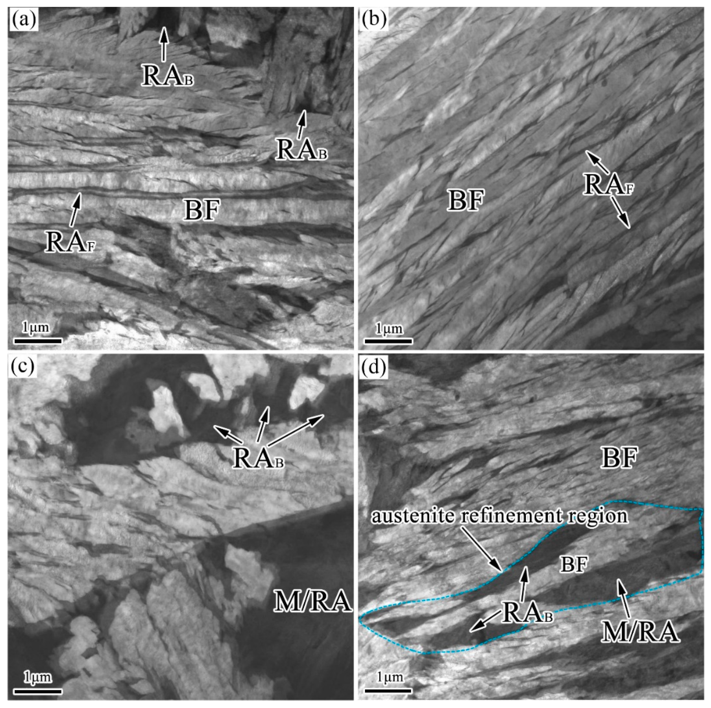
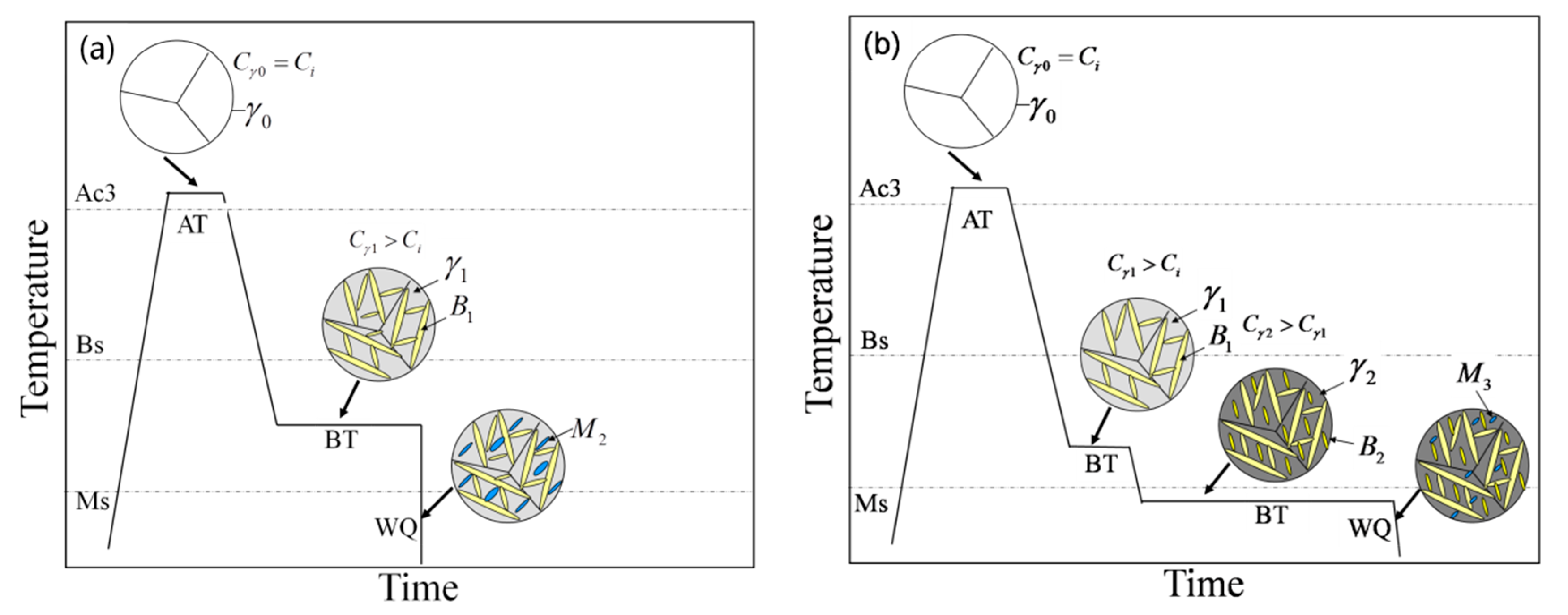
3.1. Microstructure
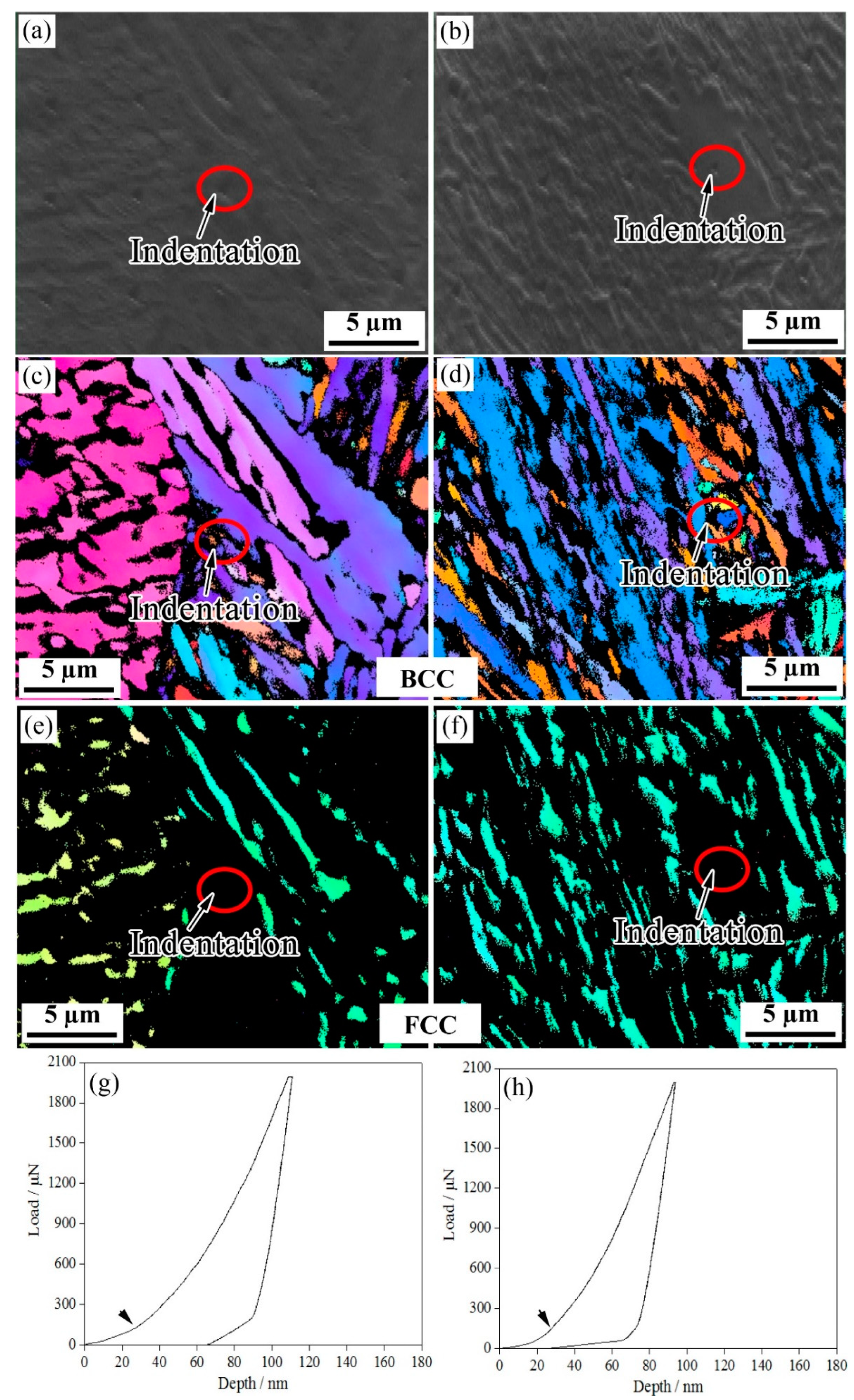
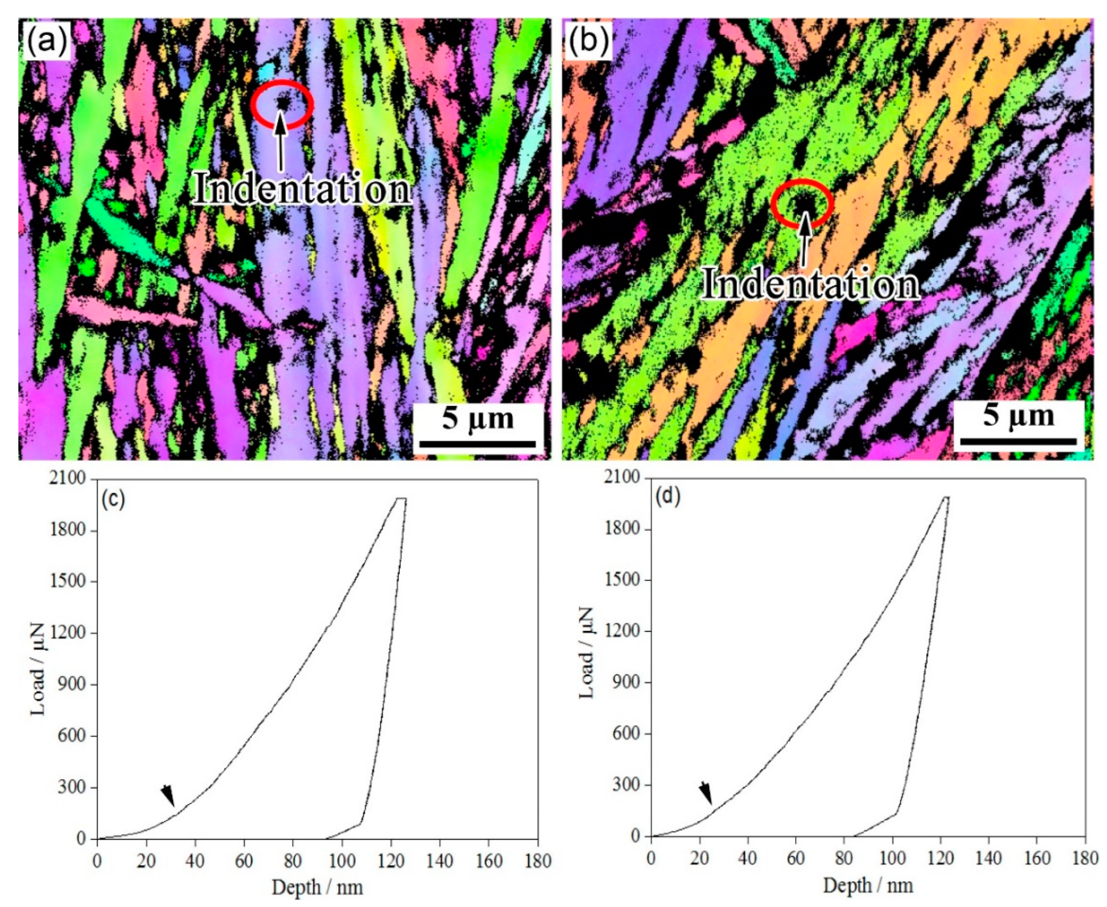
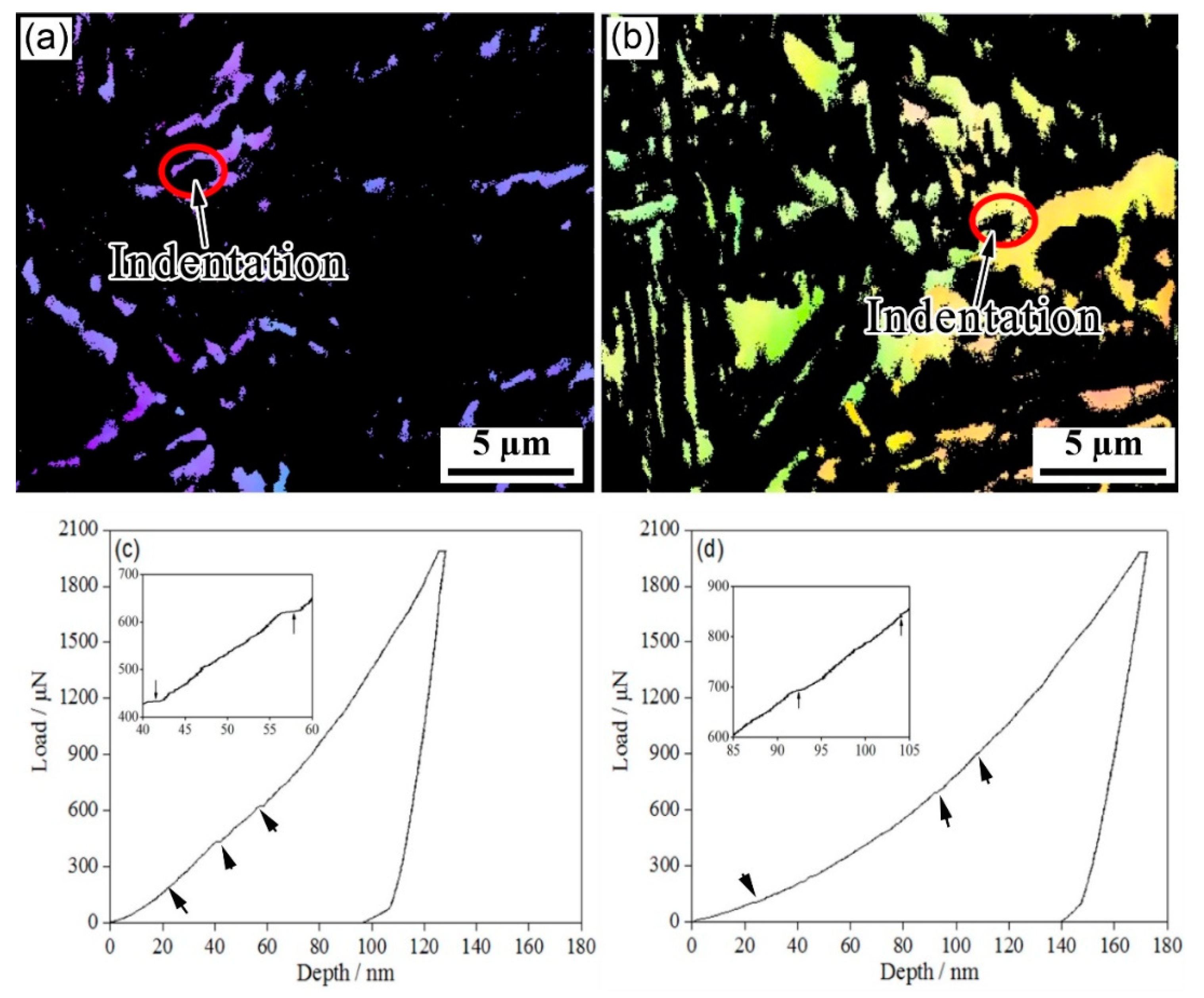
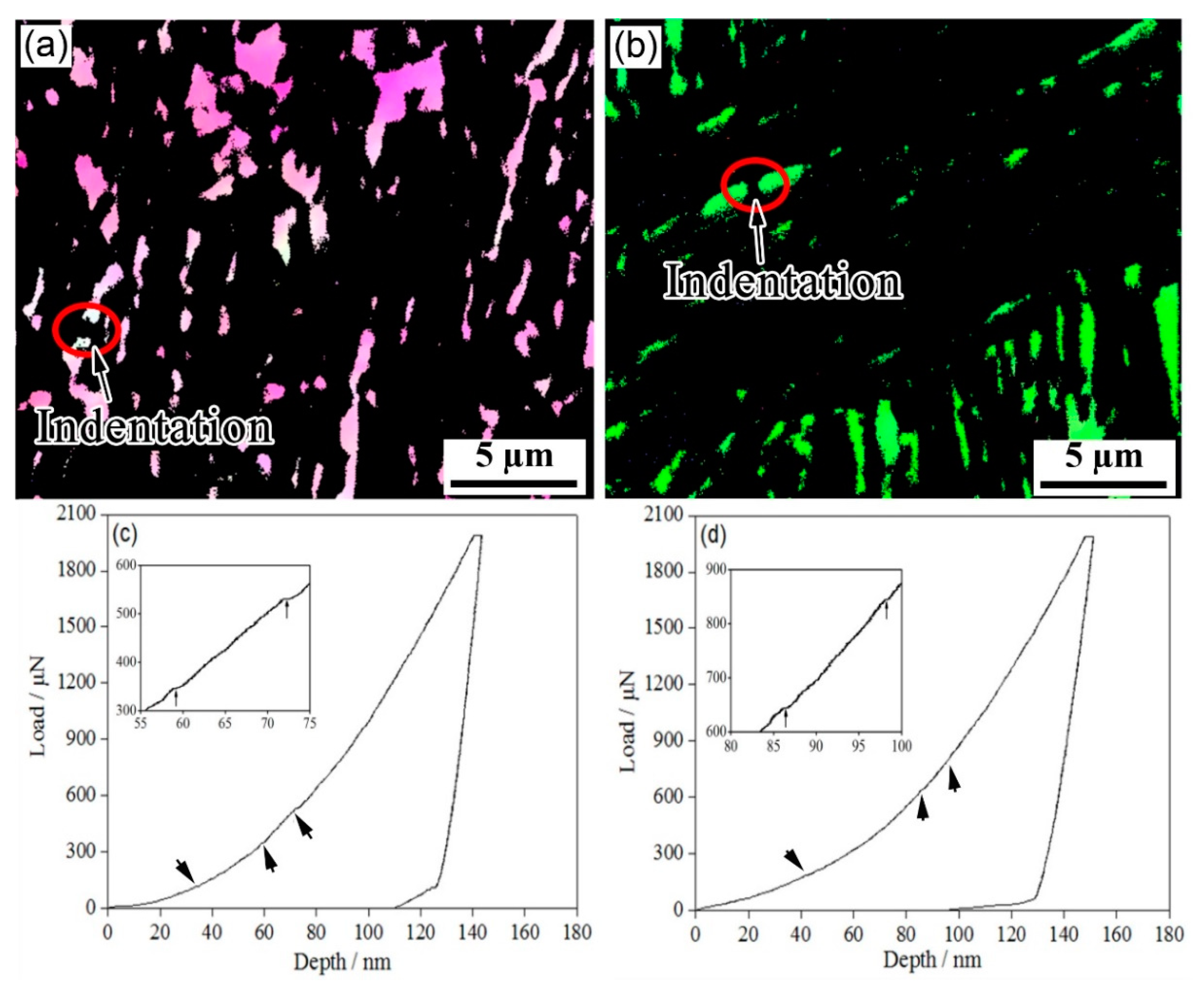
3.2. Nanoindentation Tests
3.3. Mechanical Properties
4. Discussion
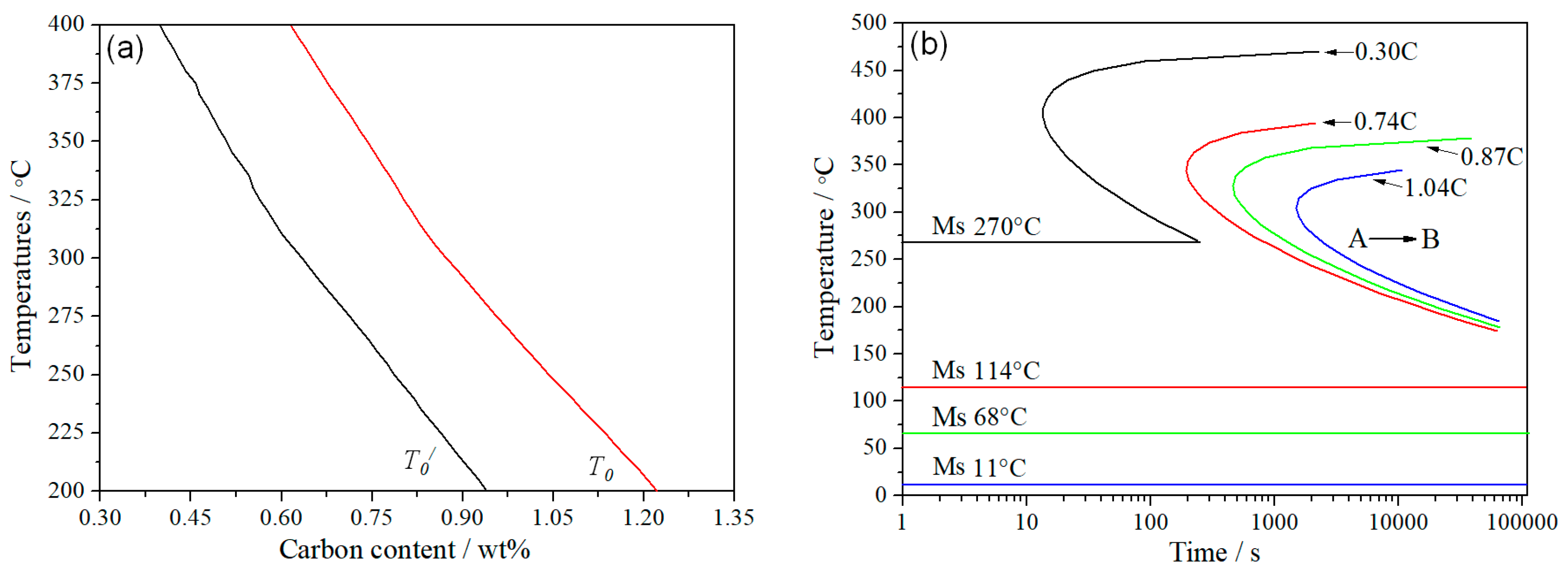
4.1. Transformation Kinetics
4.2. Deformation of Retained Austenite
5. Conclusions
- (1)
- Compared with the one-step isothermal transformation, the two-step isothermal transformation led to the size of the blocky M/RA being significantly reduced and refined and to an amount of austenite continuing to transform into a fine BF lath. Compared with blocky RA, thin-film RA had a higher surface-to-volume ratio; this made the interface larger, but the diffusion path shorter.
- (2)
- An EBSD analysis and nanoindentation tests showed that the RA film was more stable than blocky RA. The low mechanical stability of blocky RA was due to various defects that acted as nucleation sites of the martensitic transformation. Compared with the one-step treatment, the increase in stability of RA under the two-step transformation delayed the occurrence of the pop-in points. The nanohardness was also significantly improved.
Author Contributions
Funding
Institutional Review Board Statement
Informed Consent Statement
Data Availability Statement
Acknowledgments
Conflicts of Interest
References
- Caballero, F.G.; Chao, J.; Cornide, J.; García-Mateo, C.; Santofimia, M.J.; Capdevila, C. Toughness deterioration in advanced high strength bainitic steels. Mater. Sci. Eng. A 2009, 525, 87–95. [Google Scholar] [CrossRef]
- Caballero, F.G.S.; García-Mateo, M.J.; Chao, C.; de Andrés, J.; García, C. Theoretical design and advanced microstructure in super high strength steels. Mater. Des. 2009, 30, 2077–2083. [Google Scholar] [CrossRef]
- Bhadeshia, H.K.D.H.; Edmonds, D.V. Bainite in silicon steels: New composition–property approach Part 1. Met. Sci. 1983, 17, 411–419. [Google Scholar] [CrossRef]
- Bhadeshia, H.K.D.H.; Edmonds, D.V. Bainite in silicon steels: New composition–property approach Part 2. Met. Sci. 1983, 17, 420–425. [Google Scholar] [CrossRef]
- Timokhina, I.B.; Beladi, H.; Xiong, X.Y.; Adachi, Y.; Hodgson, P.D. Nanoscale microstructural characterization of a nanobainitic steel. Acta Mater. 2011, 59, 5511–5522. [Google Scholar] [CrossRef]
- Timokhina, I.B.; Hodgson, P.D.; Pereloma, E.V. Effect of microstructure on the stability of retained austenite in transformation-induced-plasticity steels. Metall. Mater. Trans. A 2004, 35, 2331–2341. [Google Scholar] [CrossRef]
- Jimenez-Melero, E.; van Dijk, N.H.; Zhao, L.; Sietsma, J.; Offerman, S.E.; Wright, J.P.; van der Zwaag, S. Characterization of individual retained austenite grains and their stability in low-alloyed TRIP steels. Acta Mater. 2007, 55, 6713–6723. [Google Scholar] [CrossRef]
- Hase, K.; Garcia-Mateo, C.; Bhadeshia, H.K.D.H. Bimodal size-distribution of bainite plates. Mater. Sci. Eng. A 2006, 438–440, 145–148. [Google Scholar] [CrossRef]
- Wang, X.L.; Wu, K.M.; Hu, F.; Yu, L.; Wan, X.L. Multi-step isothermal bainitic transformation in medium-carbon steel. Scr. Mater. 2014, 74, 56–59. [Google Scholar] [CrossRef]
- Furnémont, Q.; Kempf, M.; Jacques, P.J.; Göken, M.; Delannay, F. On the measurement of the nanohardness of the constitutive phases of TRIP-assisted multiphase steels. Mater. Sci. Eng. A 2002, 328, 26–32. [Google Scholar] [CrossRef]
- He, B.B.; Zhu, K.; Huang, M.X. On the nanoindentation behaviour of complex ferritic phases. Philos. Mag. Lett. 2014, 94, 439–446. [Google Scholar] [CrossRef]
- Fujita, N.; Ishikawa, N.; Roters, F.; Tasan, C.C.; Raabe, D. Experimental–numerical study on strain and stress partitioning in bainitic steels with martensite–austenite constituents. Int. J. Plast. 2018, 104, 39–53. [Google Scholar] [CrossRef]
- Misra, R.D.K.; Venkatsurya, P.; Wu, K.M.; Karjalainen, L.P. Ultrahigh strength martensite–austenite dual-phase steels with ultrafine structure: The response to indentation experiments. Mater. Sci. Eng. A 2013, 560, 693–699. [Google Scholar] [CrossRef]
- He, B.B.; Huang, M.X. Revealing heterogeneous C partitioning in a medium Mn steel by nanoindentation. Mater. Sci. Technol. 2017, 33, 552–558. [Google Scholar] [CrossRef]
- Zhou, S.B.; Hu, F.; Zhou, W.; Cheng, L.; Hu, C.Y.; Wu, K.M. Effect of retained austenite on impact toughness and fracture behavior of medium carbon submicron-structured bainitic steel. J. Mater. Res. Technol. 2021, 14, 1021–1034. [Google Scholar] [CrossRef]
- Ke, R.; Hu, C.; Zhong, M.; Wan, X.; Wu, K. Grain refinement strengthening mechanism of an austenitic stainless steel: Critically analyze the impacts of grain interior and grain boundary. J. Mater. Res. Technol. 2022, 17, 2999–3012. [Google Scholar] [CrossRef]
- Zhou, S.B.; Hu, F.; Wang, K.; Hu, C.Y.; Dong, H.Y.; Wan, X.L.; Cheng, S.; Misra, R.D.K.; Wu, K.M. A Study of deformation behavior and stability of retained austenite in carbide-free bainitic steel during nanoindentation process. J. Mater. Res. Technol. 2022, 20, 2221–2234. [Google Scholar] [CrossRef]
- Kadkhodapour, J.; Schmauder, S.; Raabe, D.; Ziaei-Rad, S.; Weber, U.; Calcagnotto, M. Experimental and numerical study on geometrically necessary dislocations and non-homogeneous mechanical properties of the ferrite phase in dual phase steels. Acta Mater. 2011, 59, 4387–4394. [Google Scholar] [CrossRef]
- Pöhl, F. Pop-in behavior and elastic-to-plastic transition of polycrystalline pure iron during sharp nanoindentation. Sci. Rep. 2019, 9, 15350. [Google Scholar] [CrossRef]
- Ahn, T.H.; Oh, C.S.; Kim, D.H.; Oh, K.H.; Bei, H.; George, E.P.; Han, H.N. Investigation of strain-induced martensitic transformation in metastable austenite using nanoindentation. Scr. Mater. 2010, 63, 540–543. [Google Scholar] [CrossRef]
- Yi, H.L.; Chen, P.; Bhadeshia, H.K.D.H. Optimizing the Morphology and Stability of Retained Austenite in a δ-TRIP Steel. Metall. Mater. Trans. A 2014, 45, 3512–3518. [Google Scholar] [CrossRef]
- Peet, M.J.; Bhadeshia, H.K.D.H. Materials Algorithms Project. Available online: www.msm.cam.ac.uk/map/steel/tar/mucg83.exe (accessed on 18 August 2022).
- J-MatPro 4.0. Available online: http://www.cntech.com.cn/product/JMatPro.html (accessed on 18 August 2022).
- Caballero, F.G.; Garcia-Mateo, C.; Santofimia, M.J.; Miller, M.K.; García de Andrés, C. New experimental evidence on the incomplete transformation phenomenon in steel. Acta Mater. 2009, 57, 8–17. [Google Scholar] [CrossRef]
- Xu, S.S.; Li, J.P.; Cui, Y.; Zhang, Y.; Sun, L.X.; Li, J.; Luan, J.H.; Jiao, Z.B.; Wang, X.L.; Liu, C.T.; et al. Mechanical properties and deformation mechanisms of a novel austenite-martensite dual phase steel. Int. J. Plast. 2020, 128, 102677. [Google Scholar] [CrossRef]
- Qi, X.Y.; Du, L.X.; Hu, J.; Misra, R.D.K. High-cycle fatigue behavior of low-C medium-Mn high strength steel with austenite-martensite submicron-sized lath-like structure. Mater. Sci. Eng. A 2018, 718, 477–482. [Google Scholar] [CrossRef]
- Bhadeshia, H.K.D.H. The Nature, Mechanism, and Properties of Strong Bainite. In Proceedings of the 1st International Symposium on Steel Science; The Iron and Steel Insitute of Tokyo: Tokyo, Japan, 2007; pp. 17–26. [Google Scholar]
- Xiong, Z.; Saleh, A.A.; Casillas, G.; Cui, S.; Pereloma, E.V. Phase-specific properties in a low-alloyed TRIP steel investigated using correlative nanoindentation measurements and electron microscopy. J. Mater. Sci. 2020, 55, 2578–2587. [Google Scholar] [CrossRef]
- Barnoush, A.; Welsch, M.T.; Vehoff, H. Correlation between dislocation density and pop-in phenomena in aluminum studied by nanoindentation and electron channeling contrast imaging. Scr. Mater. 2010, 63, 465–468. [Google Scholar] [CrossRef]
- Peng, F.; Gu, X.; Xu, Y. Tailoring austenite stability and mechanical behaviors of IQ&P steel via prior bainite formation. Mater. Sci. Eng. A 2021, 822, 141663. [Google Scholar] [CrossRef]
- Dong, X.X.; Liu, S.; Shen, Y.F.; Jia, N. Isothermal Holding Treatment of a Transformation-Induced Plasticity Steel for Obtaining Ultrahigh Strength and High Plasticity. J. Mater. Eng. Perform. 2021, 30, 4504–4517. [Google Scholar] [CrossRef]


| C | Si | Mn | Cr + Mo + Ni + Cu | Ti + Nb |
|---|---|---|---|---|
| 0.30 | 1.46 | 1.97 | 3.00 | 0.04 |
| Phase | One-Step | Two-Step | ||||
|---|---|---|---|---|---|---|
| Min | Max | Ave | Min | Max | Ave | |
| Blocky M/RA | 8.18 | 10.92 | 8.45 ± 1.15 | 8.62 | 12.14 | 8.25 ± 1.55 |
| BF | 4.68 | 5.76 | 5.20 ± 0.40 | 5.14 | 6.42 | 5.85 ± 0.45 |
| Blocky RA | 2.68 | 3.64 | 2.80 ± 0.30 | 2.62 | 3.78 | 3.25 ± 0.25 |
| RA Film | 2.76 | 4.38 | 3.15 ± 0.45 | 3.36 | 4.34 | 3.75 ± 0.35 |
| Specimens | Tensile Property | Impact Property at 20 °C | HV1 | ||
|---|---|---|---|---|---|
| Rm, MPa | A, % | Impact Energy, J | Average, J | ||
| One-step | 1345 | 16.0 | 23, 23, 26 | 24 | 415 |
| Two-step | 1560 | 12.5 | 43, 50, 46 | 46 | 498 |
Publisher’s Note: MDPI stays neutral with regard to jurisdictional claims in published maps and institutional affiliations. |
© 2022 by the authors. Licensee MDPI, Basel, Switzerland. This article is an open access article distributed under the terms and conditions of the Creative Commons Attribution (CC BY) license (https://creativecommons.org/licenses/by/4.0/).
Share and Cite
Zhou, S.; Hu, F.; Wang, K.; Hu, C.; Zhou, W.; Yershov, S.; Wu, K.; Zhang, Z.; Pan, X. Nanomechanics of Retained Austenite in Medium-Carbon Low-Temperature Bainitic Steel: A Critical Analysis of a One-Step versus a Two-Step Treatment. Materials 2022, 15, 5996. https://doi.org/10.3390/ma15175996
Zhou S, Hu F, Wang K, Hu C, Zhou W, Yershov S, Wu K, Zhang Z, Pan X. Nanomechanics of Retained Austenite in Medium-Carbon Low-Temperature Bainitic Steel: A Critical Analysis of a One-Step versus a Two-Step Treatment. Materials. 2022; 15(17):5996. https://doi.org/10.3390/ma15175996
Chicago/Turabian StyleZhou, Songbo, Feng Hu, Kun Wang, Chengyang Hu, Wen Zhou, Serhii Yershov, Kaiming Wu, Zhicheng Zhang, and Xianming Pan. 2022. "Nanomechanics of Retained Austenite in Medium-Carbon Low-Temperature Bainitic Steel: A Critical Analysis of a One-Step versus a Two-Step Treatment" Materials 15, no. 17: 5996. https://doi.org/10.3390/ma15175996