
The Effect of Carbon Content on the Microstructure and Mechanical Properties of Cemented Carbides with a CoNiFeCr High Entropy Alloy Binder


Abstract
:1. Introduction
2. Experimental
2.1. Material Preparation
2.2. Mechanical Properties
2.3. Microstructural Characterization
3. Results
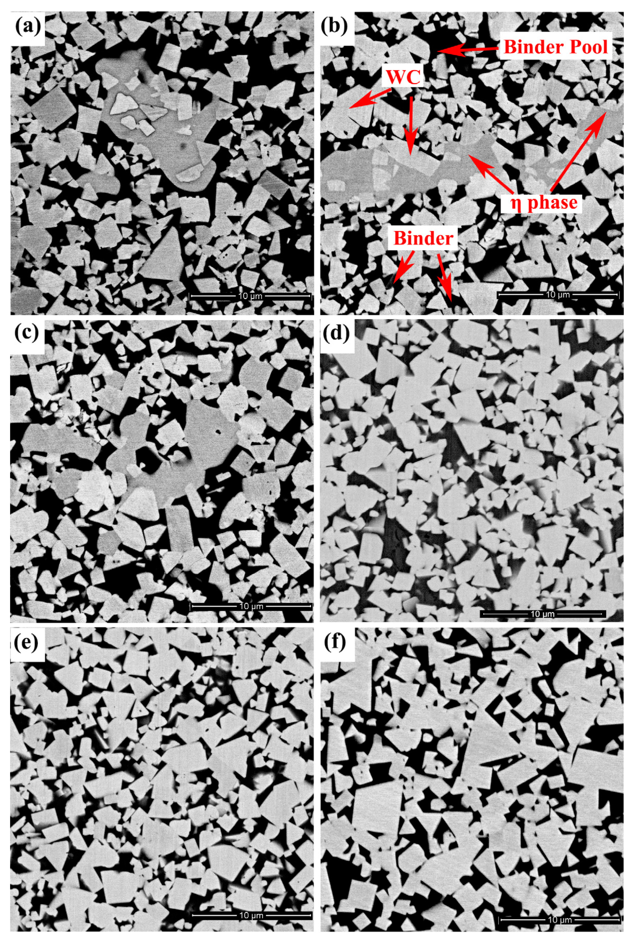
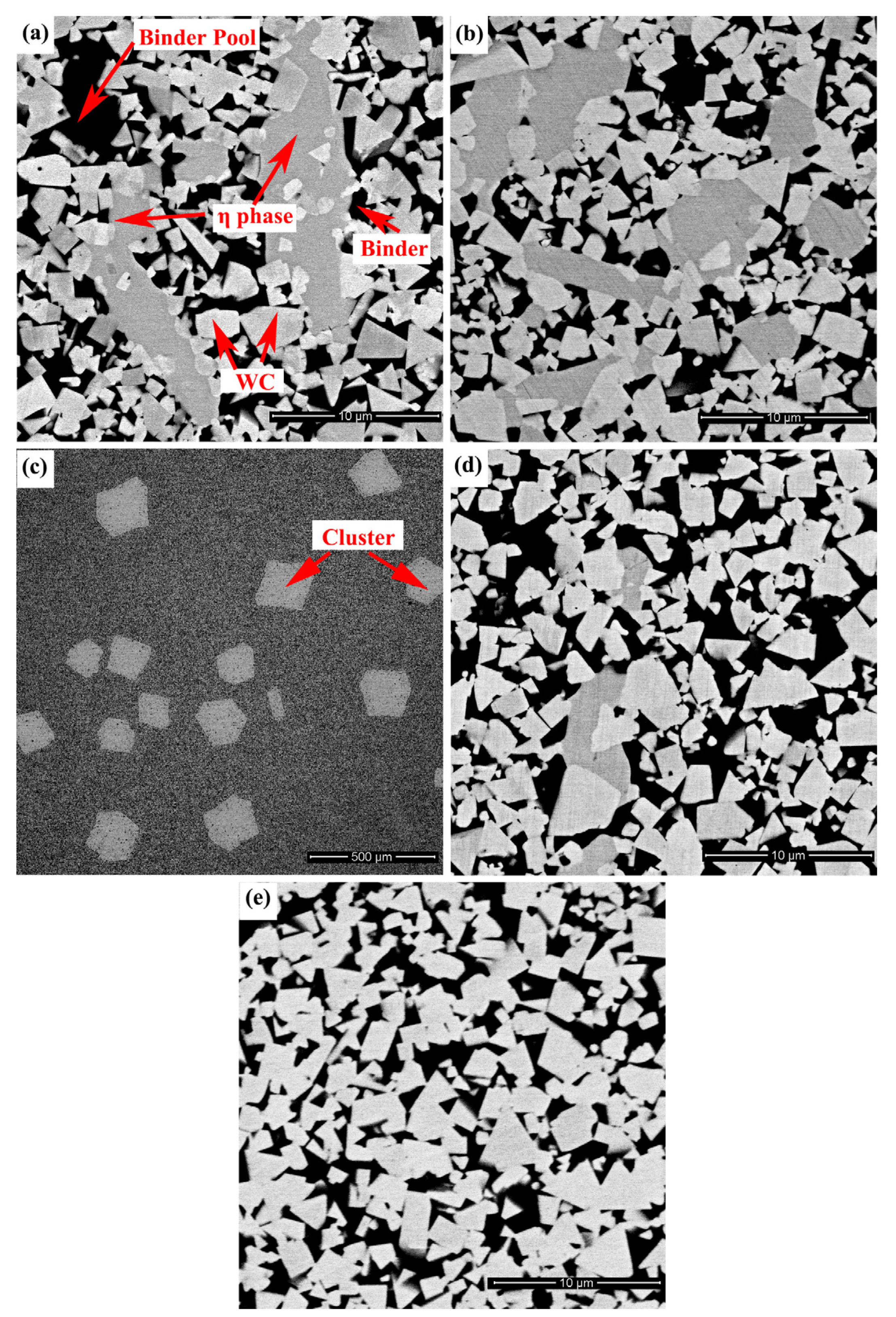
3.1. Microstructure
3.2. Mechanical Properties
4. Discussion
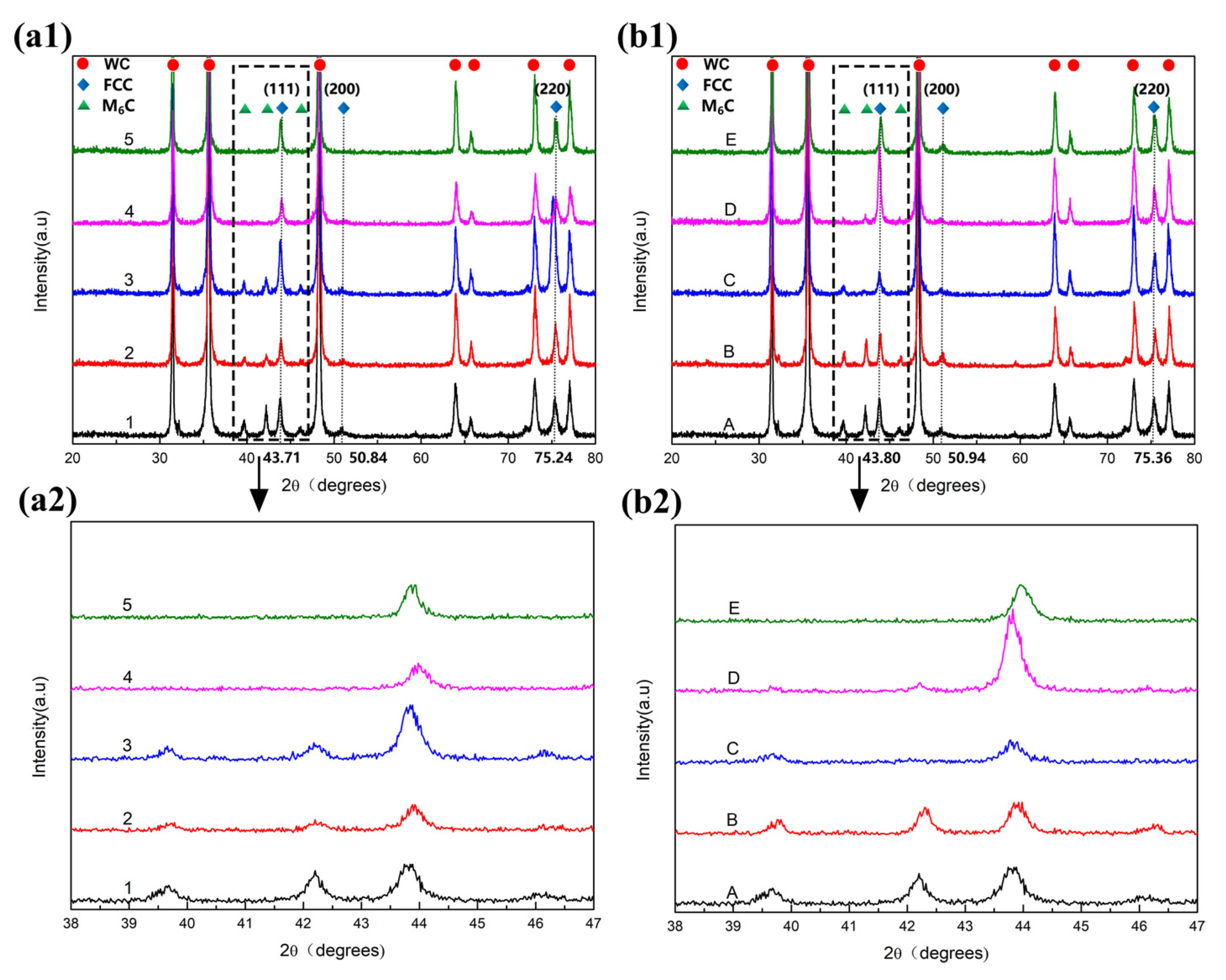
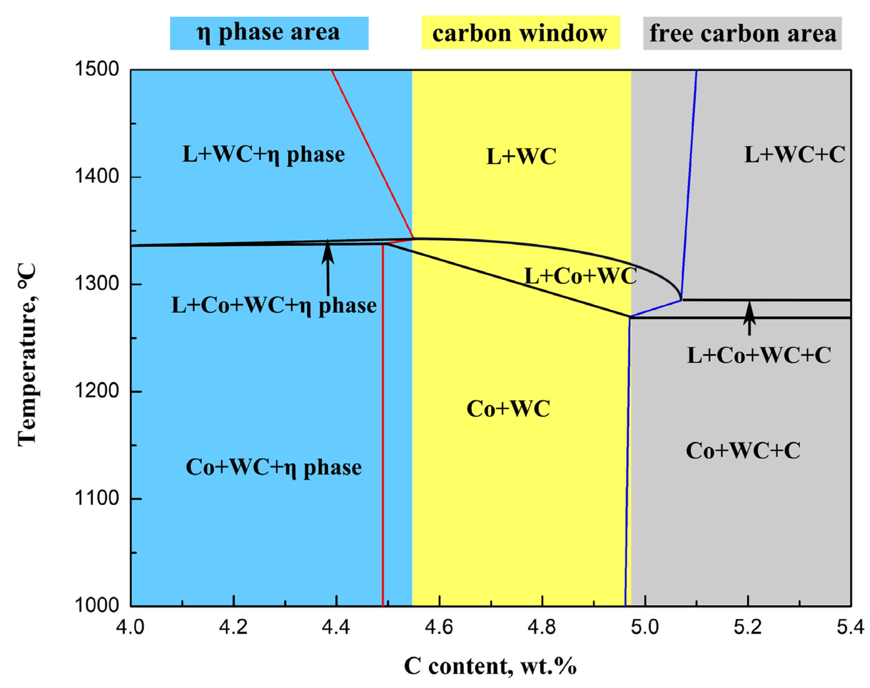
4.1. Evolution of Two-Phase Region
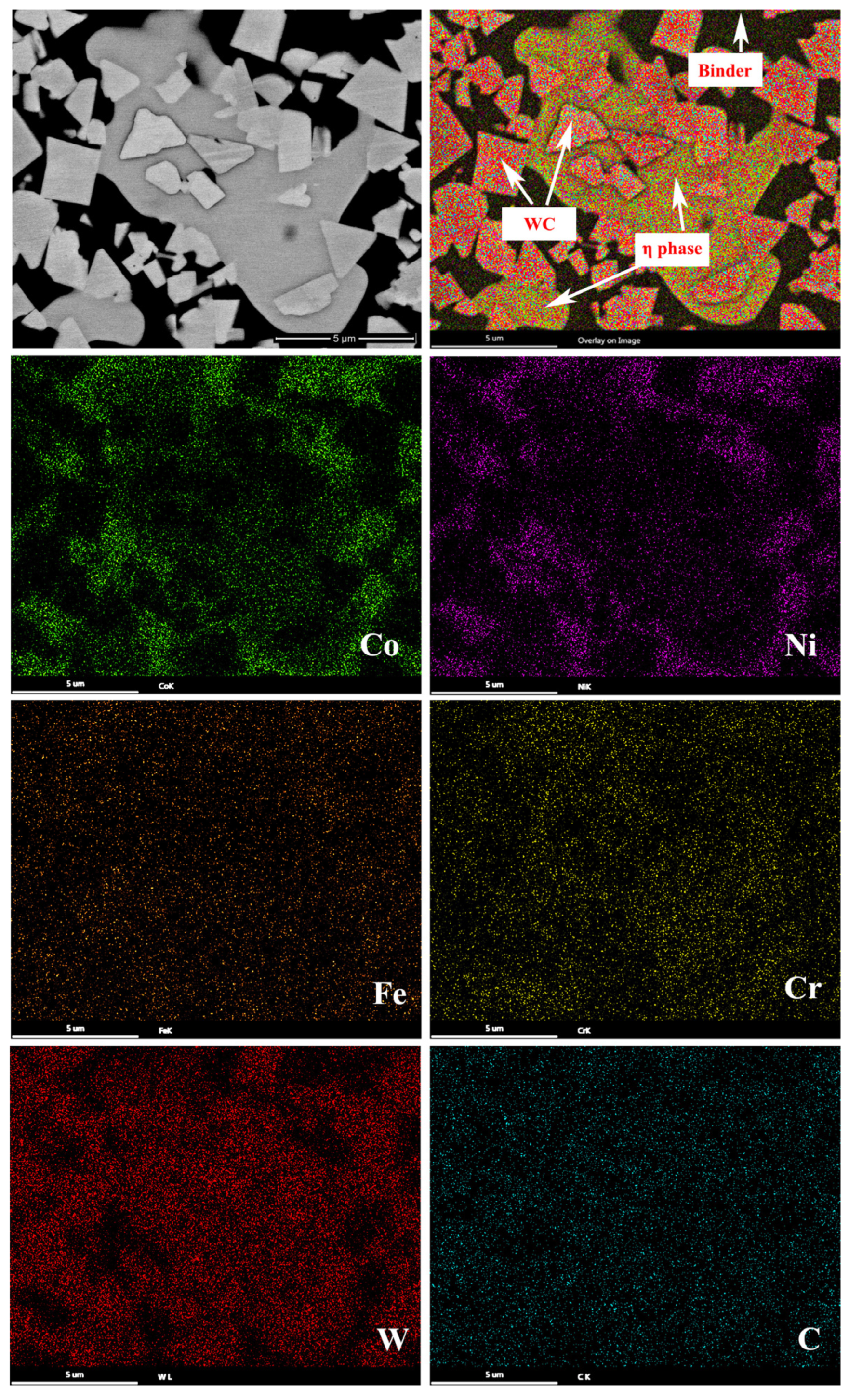
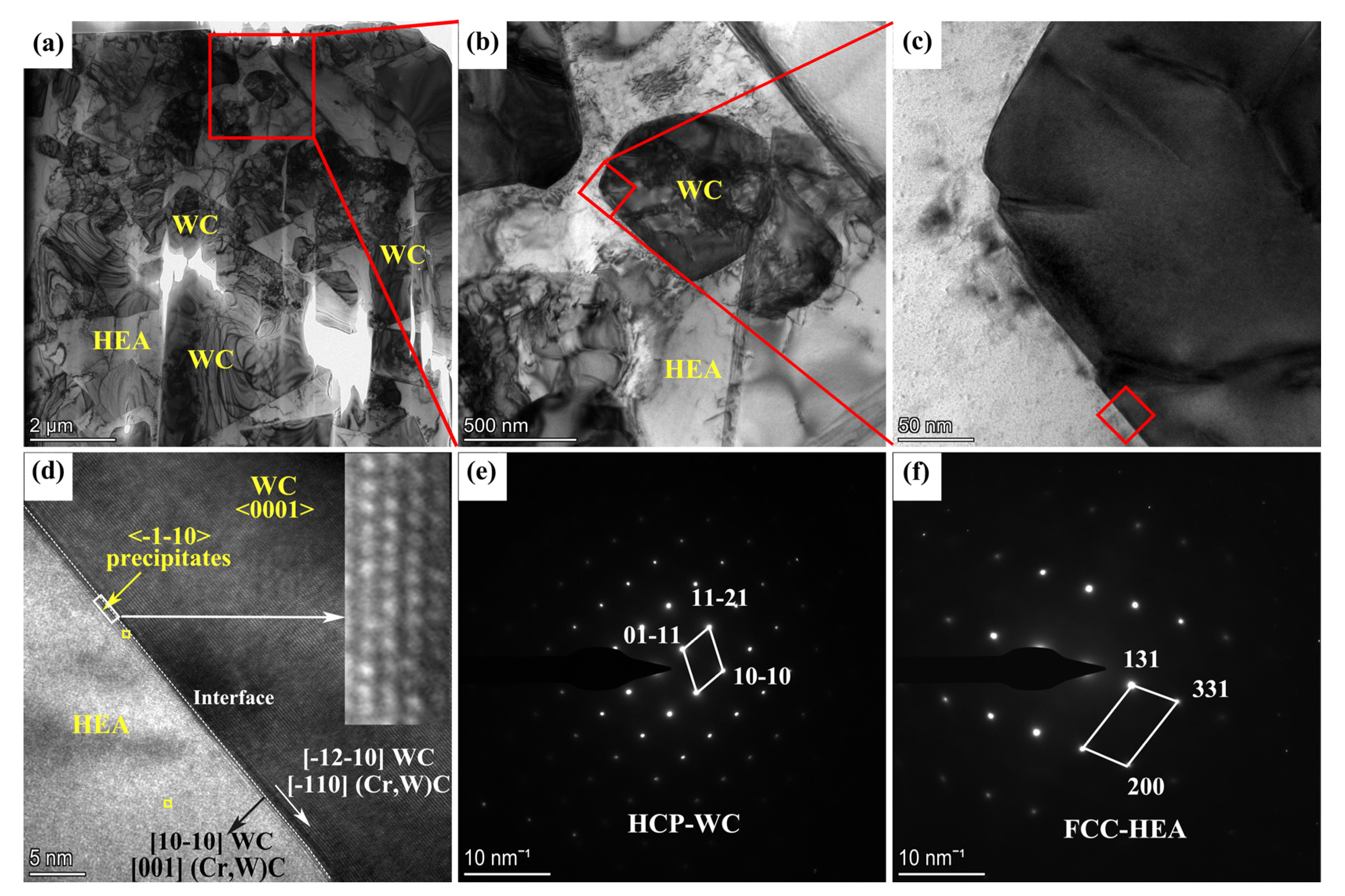
4.2. Microstructural Evolution: WC/HEA Interface
4.3. Microstructural Evolution: WC Grains and HEA Binder
4.4. Evolution of Mechanical Properties
5. Conclusions
- (1)
- Compared with WC-20Co (4.55%), the lower limit of carbon content in WC-10Co-8Ni-1Fe-1Cr (4.7–4.8%) and WC-10Co-7Ni-2Fe-1Cr (4.8–4.9%) is increased. With the addition of Ni, the width of the two-phase region increases, whereas the width of the two-phase region becomes narrower with the addition of Fe and Cr.
- (2)
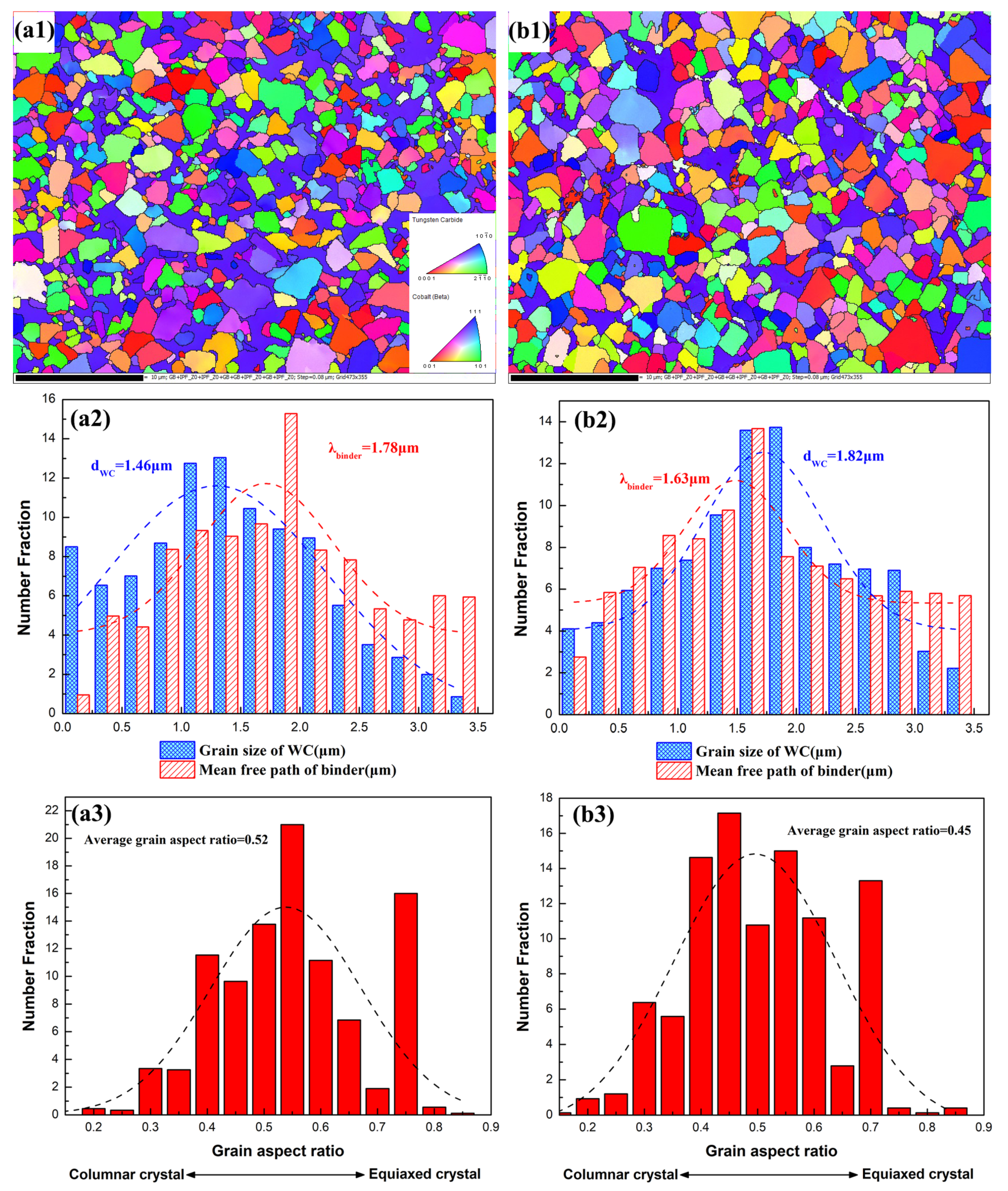
- Due to the use of the CoNiFeCr HEA binder, the (Cr,W)C phase precipitates at the WC/HEA interface. The coherent interface with a low degree of misfit is formed between WC and (Cr,W)C, thus resulting in a significant reduction in the interface energy and stress concentration. The (Cr,W)C phase exerts a pinning force (Zener-drag) on the moving grain boundaries, which effectively inhibits the growth of the WC grains. Therefore, compared with WC-Co, the WC-CoNiFeCr exhibits a smaller WC grain size, smoother grain shape and larger mean free path (MFP) of the binder.
- (3)
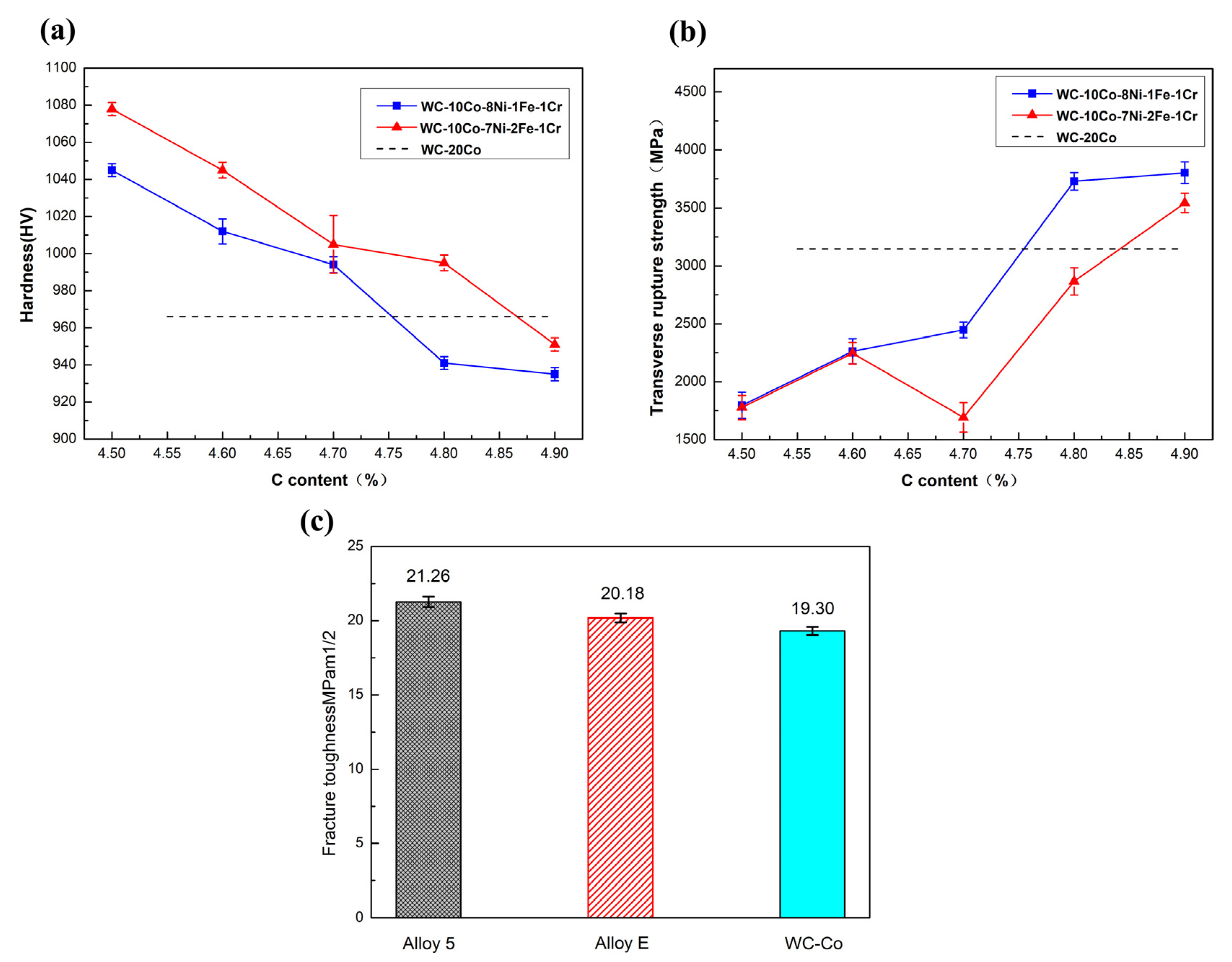
- Due to the difference in the microstructure caused by the CoNiFeCr HEA binder, the hardness of WC-10Co-8Ni-1Fe-1Cr (935 HV, 3803 MPa, 21.26 MPa.m1/2) and WC-10Co-7Ni-2Fe-1Cr (951 HV, 3543 MPa, 20.18 MPa.m1/2) is slightly reduced as compared with WC-20Co (966 HV, 3146 MPa, 19.30 MPa.m1/2); however, the TRS and fracture toughness values are observed to be significantly improved.
- (4)
- In order to solve the reduction in hardness caused by the HEA binder, we will prepare a functionally graded cemented carbide with HEA binder to form an integrated design of high hardness and toughness.
Author Contributions
Funding
Institutional Review Board Statement
Informed Consent Statement
Data Availability Statement
Conflicts of Interest
References
- Li, Z.; Xiao, W.; Ruan, X. A Finite Element Analysis of the Effects of Graphene and Carbon Nanotubes on Thermal Conductivity of Co Phase in WC-Co Carbide. Materials 2021, 14, 7656. [Google Scholar] [CrossRef] [PubMed]
- Lin, T.; Li, Q.; Han, Y.; Song, K.; Wang, X.; Shao, H.; Dong, J.; Wang, H.; Deng, X. Effects of Nb and NbC additives on microstructure and properties of WC-Co-Ni cemented carbides. Int. J. Refract. Met. Hard Mater. 2022, 103, 105782. [Google Scholar] [CrossRef]
- Wachowicz, J.; Dembiczak, T.; Stradomski, G.; Bałaga, Z.; Jasińska, J.; Rydz, D.; Dyner, M. The Analysis of Erosive Wear Resistance of WC-Co Carbides Obtained by Spark Plasma Sintering Method. Materials 2021, 14, 7326. [Google Scholar] [CrossRef] [PubMed]
- Katiyar, P.K.; Maurya, R.; Singh, P.K. Failure Behavior of Cemented Tungsten Carbide Materials: A Case Study of Mining Drill Bits. J. Mater. Eng. Perform. 2021, 30, 6090–6106. [Google Scholar] [CrossRef]
- Rong, H.; Peng, Z.; Ren, X.; Peng, Y.; Wang, C.; Fu, Z.; Miao, H. Ultrafine WC–Ni cemented carbides fabricated by spark plasma sintering. Mater. Sci. Eng. A 2012, 532, 543–547. [Google Scholar] [CrossRef]
- Shi, K.H.; Zhou, K.C.; Li, Z.Y.; Zhang, D.; Zan, X.Q. Microstructure and formation process of Ni-pool defect in WC–8Ni cemented carbides. Trans. Nonferrous Met. Soc. China 2015, 25, 873–878. [Google Scholar] [CrossRef]
- Qian, C.; Li, K.; Guo, X.Y.; Liu, B.; Long, Z.Y.; Liu, Y. Effect of WC grain size on mechanical properties and microstructures of cemented carbide with medium entropy alloy Co-Ni-Fe binder. J. Cent. South Univ. 2020, 27, 1146–1157. [Google Scholar] [CrossRef]
- Gao, S.; Zhen, M.; Zhu, J.; Chen, J. Mechanism of adhesion failure during interrupted cutting with cemented carbide tools: Experimental and ab-initio perspective. Int. J. Refract. Met. Hard Mater. 2021, 98, 105549. [Google Scholar] [CrossRef]
- Farag, S.; Konyashin, I.; Ries, B. The influence of grain growth inhibitors on the microstructure and properties of submicron, ultrafine and nano-structured hardmetals—A review. Int. J. Refract. Met. Hard Mater. 2018, 77, 12–30. [Google Scholar] [CrossRef]
- Sun, Y.; Su, W.; Yang, H.; Ruan, J. Effects of WC particle size on sintering behavior and mechanical properties of coarse grained WC–8Co cemented carbides fabricated by unmilled composite powders. Ceram. Int. 2015, 41, 14482–14491. [Google Scholar] [CrossRef]
- Katiyar, P.K. A comprehensive review on synergy effect between corrosion and wear of cemented tungsten carbide tool bits: A mechanistic approach. Int. J. Refract. Met. Hard Mater. 2020, 92, 105315. [Google Scholar] [CrossRef]
- Katiyar, P.K.; Randhawa, N.S. Corrosion behavior of WC-Co tool bits in simulated (concrete, soil, and mine) solutions with and without chloride additions. Int. J. Refract. Met. Hard Mater. 2019, 85, 105062. [Google Scholar] [CrossRef]
- Peng, W.; Hao, S.; Zhao, L.; Li, Z.; Chen, J.; Wang, X.; Wang, K. Thermal stability of modified surface microstructure on WC-Co cemented carbide after high current pulsed electron beam irradiation. J. Alloys Compd. 2020, 829, 154545. [Google Scholar] [CrossRef]
- Mikado, H.; Ishihara, S.; Oguma, N.; Masuda, K.; Kitagawa, S.; Kawamura, S. Effect of stress ratio on fatigue lifetime and crack growth behavior of WC–Co cemented carbide. Trans. Nonferrous Met. Soc. China 2014, 24, s14–s19. [Google Scholar] [CrossRef]
- Astacio, R.; Gallardo, J.M.; Cintas, J.; Montes, J.M.; Cuevas, F.G.; Prakash, L.; Torres, Y. Fracture toughness of cemented carbides obtained by electrical resistance sintering. Int. J. Refract. Met. Hard Mater. 2019, 80, 259–269. [Google Scholar] [CrossRef]
- Soleimanpour, A.M.; Abachi, P.; Simchi, A. Microstructure and mechanical properties of WC–10Co cemented carbide containing VC or (Ta, Nb)C and fracture toughness evaluation using different models. Int. J. Refract. Met. Hard Mater. 2012, 31, 141–146. [Google Scholar] [CrossRef]
- Holmström, E.; Lizarraga, R.; Linder, D.; Salmasi, A.; Wang, W.; Kaplan, B.; Vitos, L. High entropy alloys: Substituting for cobalt in cutting edge technology. Appl. Mater. Today 2018, 12, 322–329. [Google Scholar] [CrossRef]
- Chen, W.; Ding, X.; Feng, Y.; Liu, X.; Liu, K.; Lu, Z.P.; Chen, X.Q. Vacancy formation enthalpies of high-entropy FeCoCrNi alloy via first-principles calculations and possible implications to its superior radiation tolerance. J. Mater. Sci. Technol. 2018, 34, 355–364. [Google Scholar] [CrossRef]
- Linder, D.; Holmström, E.; Norgren, S. High entropy alloy binders in gradient sintered hardmetal. Int. J. Refract. Met. Hard Mater. 2018, 71, 217–220. [Google Scholar] [CrossRef]
- Velo, I.L.; Gotor, F.J.; Alcalá, M.D.; Real, C.; Córdoba, J.M. Fabrication and characterization of WC-HEA cemented carbide based on the CoCrFeNiMn high entropy alloy. J. Alloys Compd. 2018, 746, 1–8. [Google Scholar] [CrossRef]
- Rogachev, A.S.; Vadchenko, S.G.; Kochetov, N.A.; Kovalev, D.Y.; Kovalev, I.D.; Shchukin, A.S.; Politano, O. Combustion synthesis of TiC-based ceramic-metal composites with high entropy alloy binder. J. Eur. Ceram. Soc. 2019, 40, 2527–2532. [Google Scholar] [CrossRef]
- De la Obra, A.G.; Sayagués, M.J.; Chicardi, E.; Gotor, F.J. Development of Ti(C,N)-based cermets with (Co,Fe,Ni)-based high entropy alloys as binder phase. J. Alloys Compd. 2020, 814, 152218. [Google Scholar] [CrossRef]
- Calderon, R.; Edtmaier, C.; Schubert, W.D. Novel binders for WC-based cemented carbides with high Cr contents. Int. J. Refract. Met. Hard Mater. 2019, 85, 105063. [Google Scholar] [CrossRef]
- Dong, D.; Xiang, X.; Huang, B.; Xiong, H.; Zhang, L.; Shi, K.; Liao, J. Microstructure and properties of WC-Co/CrMnFeCoNi composite cemented carbides. Vacuum 2020, 179, 109571. [Google Scholar] [CrossRef]
- Biurrun, T.S.; Ezquerra, B.L.; Cabezas, L.L.; Moreno, J.M.S. Effect of milling conditions and binder phase content on liquid phase sintering of heat treatable WC-Ni-Co-Cr-Al-Ti cemented carbides. Int. J. Refract. Met. Hard Mater. 2020, 88, 105202. [Google Scholar] [CrossRef]
- Qian, C.; Liu, Y.; Cheng, H.; Li, K.; Liu, B. Effect of the carbon content on the morphology evolution of the η phase in cemented carbides with the CoNiFeCr high entropy alloy binder. Int. J. Refract. Met. Hard Mater. 2022, 102, 105731. [Google Scholar] [CrossRef]
- Peng, Z.; Yong, D.; Walter, L. Morphology of η phase in cemented carbides with Fe-based binders influenced by carbon content and nitrogen atmosphere. Ceram. Int. 2019, 45, 20774–20779. [Google Scholar]
- Fernandes, C.M.; Senos, A.; Vieira, M.T. Control of eta carbide formation in tungsten carbide powders sputter-coated with (Fe/Ni/Cr). Int. J. Refract. Met. Hard Mater. 2007, 25, 310–317. [Google Scholar] [CrossRef] [Green Version]
- Gao, Y.; Luo, B.H.; He, K.J.; Zhang, W.W.; Bai, Z.H. Effect of Fe/Ni ratio on the microstructure and properties of WC-Fe-Ni-Co cemented carbides. Ceram. Int. 2018, 44, 2030–2041. [Google Scholar] [CrossRef]
- Gao, Y.; Luo, B.H.; He, K.J.; Jing, H.B.; Bai, Z.H.; Chen, W.; Zhang, W.W. Mechanical properties and microstructure of WC-Fe-Ni-Co cemented carbides prepared by vacuum sintering. Vacuum 2017, 143, 271–282. [Google Scholar] [CrossRef]
- Delanoë, A.; Bacia, M.; Pauty, E.; Lay, S.; Allibert, C.H. Cr-rich layer at the WC/Co interface in Cr-doped WC-Co cermets: Segregation or metastable carbide? J. Cryst. Growth 2004, 270, 219–227. [Google Scholar] [CrossRef]
- Luo, W.; Liu, Y.; Shen, J. Effects of binders on the microstructures and mechanical properties of ultrafine WC-10%AlxCoCrCuFeNi composites by spark plasma sintering. J. Alloys Compd. 2019, 791, 540–549. [Google Scholar] [CrossRef]
- Zhou, P.L.; Xiao, D.H.; Zhou, P.F.; Yuan, T.C. Microstructure and properties of ultrafine grained AlCrFeCoNi/WC cemented carbides. Ceram. Int. 2018, 44, 17160–17166. [Google Scholar] [CrossRef]
- Qian, C.; Li, K.; Cheng, H.; Zhang, W.; Jiang, X.; Liu, Y. Fracture behavior of cemented carbides with CoNiFe medium entropy alloy binder. Int. J. Refract. Met. Hard Mater. 2021, 98, 105547. [Google Scholar] [CrossRef]
- Li, D.; Liu, Y.; Ye, J.; Chen, X.; Wang, L. The enhancement of the microstructure and mechanical performances of ultrafine WC-Co cemented carbides by optimizing Cr2(C,N) addition and WC particle sizes. Int. J. Refract. Met. Hard Mater. 2021, 97, 105518. [Google Scholar] [CrossRef]
- Chen, C.S.; Yang, C.C.; Chai, H.Y.; Yeh, J.W.; Chau, J.L.H. Novel cermet material of WC/multi-element alloy. Int. J. Refract. Met. Hard Mater. 2014, 43, 200–204. [Google Scholar] [CrossRef]
- Mueller-Grunz, A.; Alveen, P.; Rassbach, S.; Useldinger, R.; Moseley, S. The manufacture and characterization of WC-(Al)CoCrCuFeNi cemented carbides with nominally high entropy alloy binders. Int. J. Refract. Met. Hard Mater. 2019, 84, 105032. [Google Scholar] [CrossRef]


| Samples | Composition/wt.% | Carbon Content in Alloy | Vbinder (%) | Vη (%) | CWC | |||||
|---|---|---|---|---|---|---|---|---|---|---|
| WC | W | Co | Ni | Fe | Cr2C3 | |||||
| Alloy 1 | 70.96 | 8.89 | 10 | 8 | 1 | 1.15 | 4.5% | 24.18 | 22.1 | 0.283 |
| Alloy 2 | 72.59 | 7.26 | 10 | 8 | 1 | 1.15 | 4.6% | 25.1 | 13.7 | 0.305 |
| Alloy 3 | 74.23 | 5.62 | 10 | 8 | 1 | 1.15 | 4.7% | 28.2 | 10.3 | 0.307 |
| Alloy 4 | 75.86 | 3.99 | 10 | 8 | 1 | 1.15 | 4.8% | 31.8 | - | 0.335 |
| Alloy 5 | 77.49 | 2.36 | 10 | 8 | 1 | 1.15 | 4.9% | 32.2 | - | 0.333 |
| Alloy A | 70.96 | 8.89 | 10 | 7 | 2 | 1.15 | 4.5% | 20.3 | 23.7 | 0.289 |
| Alloy B | 72.59 | 7.26 | 10 | 7 | 2 | 1.15 | 4.6% | 23.2 | 15.6 | 0.301 |
| Alloy C | 74.23 | 5.62 | 10 | 7 | 2 | 1.15 | 4.7% | - | - | - |
| Alloy D | 75.86 | 3.99 | 10 | 7 | 2 | 1.15 | 4.8% | 27.6 | 11.0 | 0.307 |
| Alloy E | 77.49 | 2.36 | 10 | 7 | 2 | 1.15 | 4.9% | 33.2 | - | 0.328 |
| WC-Co | 80 | — | 20 | — | — | — | 4.9% | 34.6 | - | 0.322 |
| W | C | Co | Ni | Fe | Cr | Cr/Co+Ni+Fe+Cr | |
|---|---|---|---|---|---|---|---|
| Binder | 4.29 | 0.79 | 50.92 | 35.39 | 4.57 | 4.04 | 0.043 |
| Interface | 38.11 | 21.42 | 18.47 | 12.06 | 2.39 | 7.55 | 0.187 |
| Samples | Composition of Binder (wt.%) |
|---|---|
| Alloy 1 | 30Co-24Ni-3Fe-3Cr-40W |
| Alloy 2 | 34Co-29Ni-4Fe-3Cr-30W |
| Alloy 3 | 36Co-30Ni-4Fe-3Cr-27W |
| Alloy 4 | 38Co-30Ni-4Fe-4Cr-24W |
| Alloy 5 | 39Co-31Ni-4Fe-4Cr-22W |
| Alloy A | 30Co-23Ni-7Fe-3Cr-37W |
| Alloy B | 32Co-24Ni-7Fe-3Cr-34W |
| Alloy C | 34Co-25Ni-7Fe-3Cr-31W |
| Alloy D | 36Co-26Ni-7Fe-4Cr-27W |
| Alloy E | 37Co-27Ni-8Fe-4Cr-24W |
| WC-Co | 61Co-39W |
| Samples | Hardness (HV) | TRS (MPa) | KIc (MPam1/2) |
|---|---|---|---|
| Alloy 5 | 935 | 3803 | 21.26 |
| Alloy E | 951 | 3543 | 20.18 |
| WC-Co | 966 | 3146 | 19.30 |
| WC-CoNiFe [29] | 1087 | 3069 | 18.97 |
| WC-Al0.5CrCoCuFeNi [36] | 1413 | - | 17.4 |
| WC-Co/CrMnFeCoNi [24] | 1330 | - | 17.8 |
| WC-CoCrCuFeNi (low carbon) [37] | 1085 | - | 7.8 |
| WC-CoCrCuFeNi (high carbon) [37] | 922 | - | 7.6 |
| WC-AlCrFeCoNi [33] | 1600 | - | 9.2 |
Publisher’s Note: MDPI stays neutral with regard to jurisdictional claims in published maps and institutional affiliations. |
© 2022 by the authors. Licensee MDPI, Basel, Switzerland. This article is an open access article distributed under the terms and conditions of the Creative Commons Attribution (CC BY) license (https://creativecommons.org/licenses/by/4.0/).
Share and Cite
Qian, C.; Liu, Y.; Cheng, H.; Li, K.; Liu, B.; Zhang, X. The Effect of Carbon Content on the Microstructure and Mechanical Properties of Cemented Carbides with a CoNiFeCr High Entropy Alloy Binder. Materials 2022, 15, 5780. https://doi.org/10.3390/ma15165780
Qian C, Liu Y, Cheng H, Li K, Liu B, Zhang X. The Effect of Carbon Content on the Microstructure and Mechanical Properties of Cemented Carbides with a CoNiFeCr High Entropy Alloy Binder. Materials. 2022; 15(16):5780. https://doi.org/10.3390/ma15165780
Chicago/Turabian StyleQian, Cheng, Yong Liu, Huichao Cheng, Kun Li, Bin Liu, and Xin Zhang. 2022. "The Effect of Carbon Content on the Microstructure and Mechanical Properties of Cemented Carbides with a CoNiFeCr High Entropy Alloy Binder" Materials 15, no. 16: 5780. https://doi.org/10.3390/ma15165780