
Effects of Infill Plate’s Interconnection and Boundary Element Stiffness on Steel Plate Shear Walls’ Seismic Performance

Abstract
:1. Introduction
2. Materials and Methods
2.1. Verification
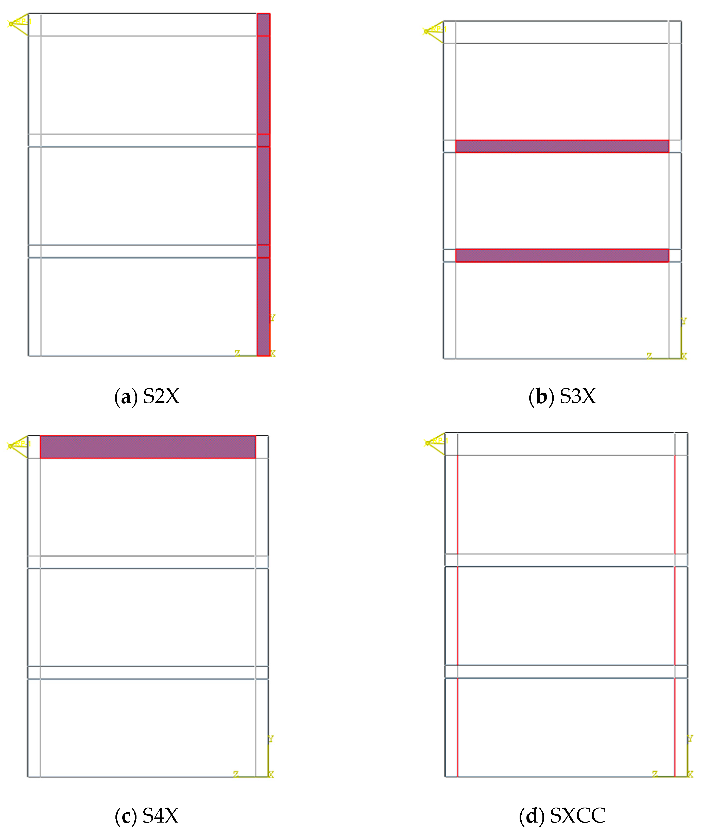
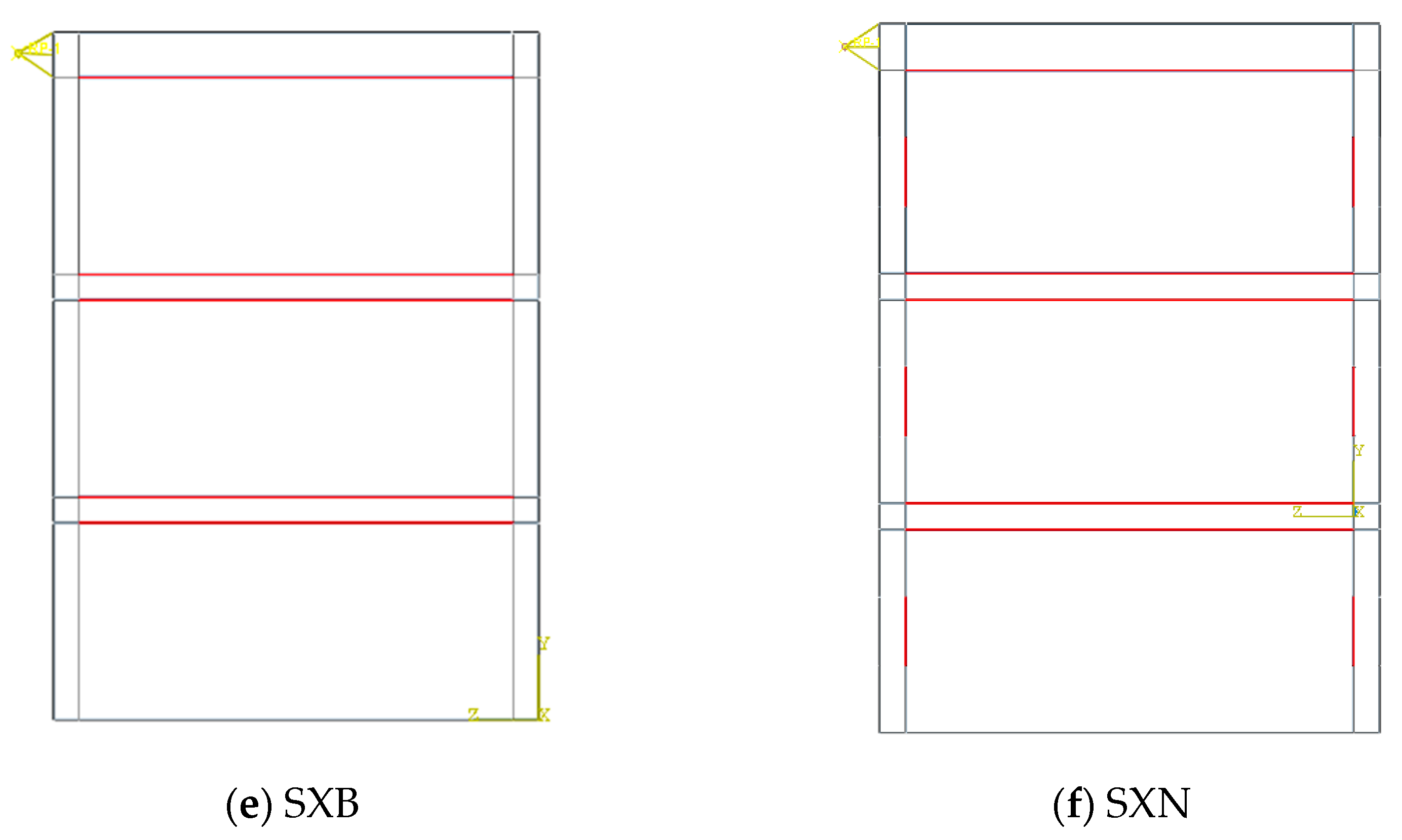
2.2. Description of Models
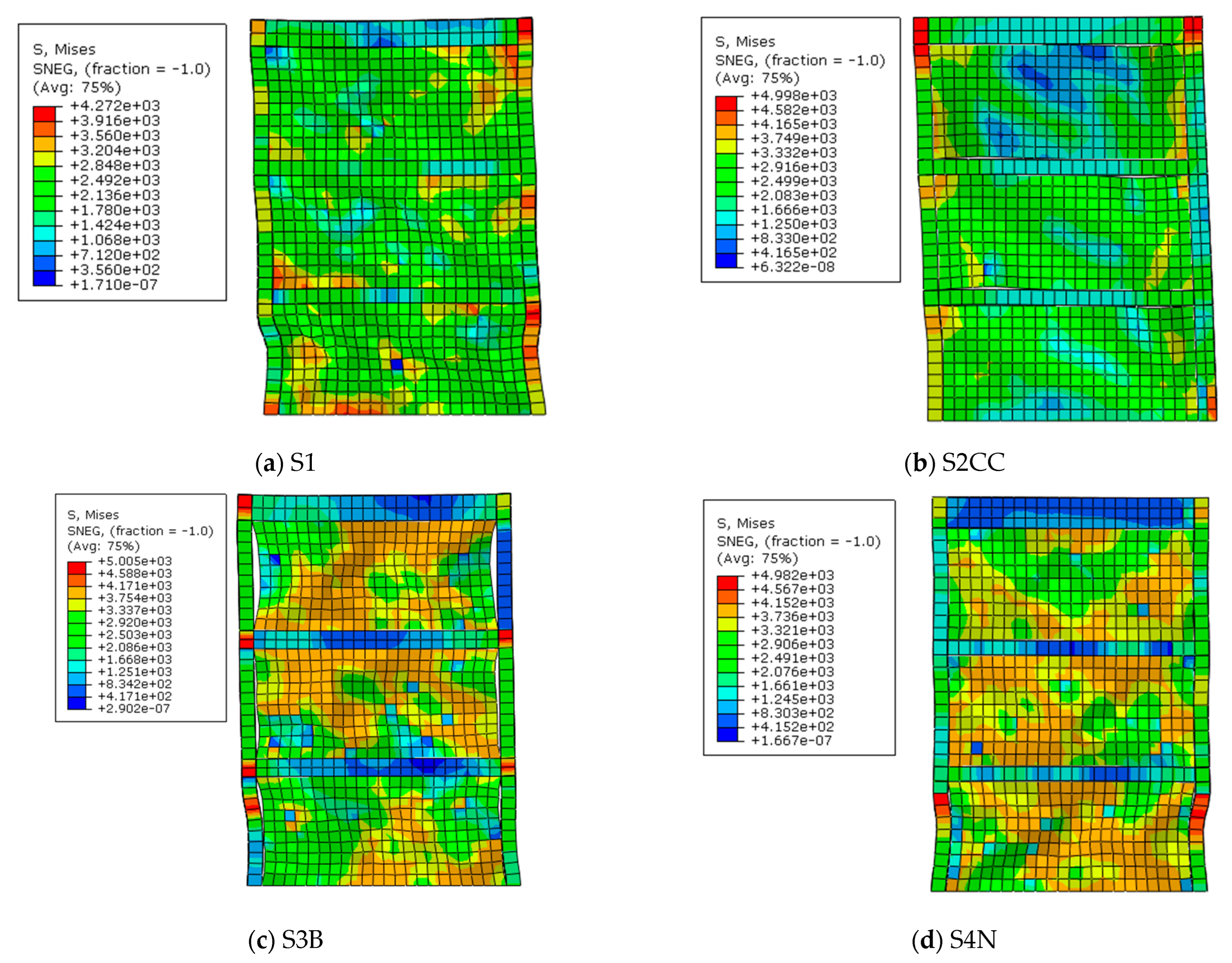
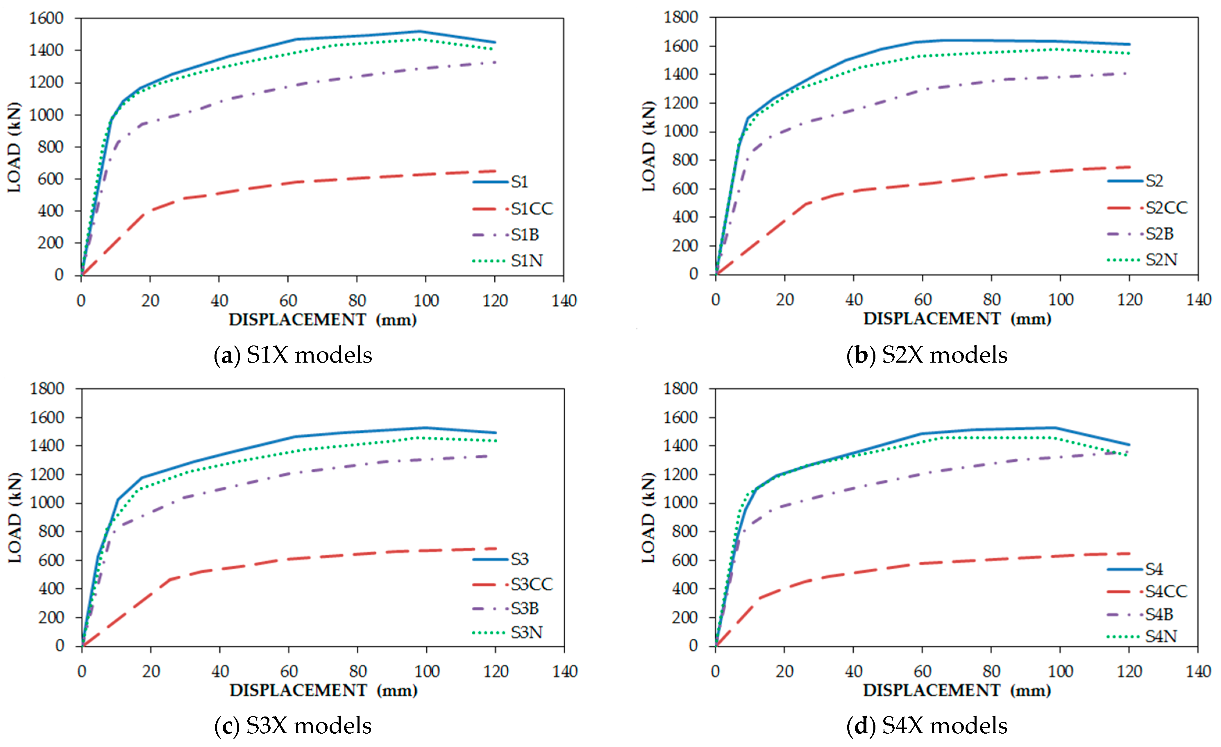
3. Results and Discussion
4. Conclusions
Author Contributions
Funding
Informed Consent Statement
Conflicts of Interest
References
- Farzampour, A.; Mansouri, I.; Lee, C.-H.; Sim, H.-B.; Hu, J.W. Analysis and design recommendations for corrugated steel plate shear walls with a reduced beam section. Thin-Walled Struct. 2018, 132, 658–666. [Google Scholar] [CrossRef]
- He, J.; Lin, S.; Li, Y.; Dong, X.; Chen, S. Genetic Algorithm for Optimal Placement of Steel Plate Shear Walls for Steel Frames. Buildings 2022, 12, 835. [Google Scholar] [CrossRef]
- Zhou, M.; Yang, D.; Zhang, J.; An, L. Stress analysis of linear elastic non-prismatic beams with corrugated steel webs. Thin-Walled Struct. 2017, 119, 653–661. [Google Scholar] [CrossRef]
- Paslar, N.; Farzampour, A.; Hatami, F. Infill plate interconnection effects on the structural behavior of steel plate shear walls. Thin-Walled Struct. 2020, 149, 106621. [Google Scholar] [CrossRef]
- Zhang, X.; Zhang, A.-L.; Liu, X. Seismic performance of discontinuous cover-plate connection for prefabricated steel plate shear wall. J. Constr. Steel Res. 2019, 160, 374–386. [Google Scholar] [CrossRef]
- Elsheikh, A.H.; Guo, J.; Huang, Y.; Ji, J.; Lee, K.-M. Temperature field sensing of a thin-wall component during machining: Numerical and experimental investigations. Int. J. Heat Mass Transf. 2018, 126, 935–945. [Google Scholar] [CrossRef]
- Ma, X.; Hu, Y.; Jiang, L.; Jiang, L.; Nie, G.; Zheng, H. Study on the Seismic Performance of Stiffened Corrugated Steel Plate Shear Walls with Atmospheric Corrosion. J. Mater. 2022, 15, 4920. [Google Scholar] [CrossRef]
- Xu, H.; Duan, K.; Li, C.; Qiang, X.; Liu, Y. Experimental and Numerical Study on Shear Behavior of Stiffened Thin Steel Plate Shear Walls by New Welding Process. Infrastructures 2022, 7, 58. [Google Scholar] [CrossRef]
- Tan, Z.; Zhao, Q.; Zhao, Y.; Yu, C. Probabilistic Seismic Assessment of CoSPSW Structures Using Fragility Functions. Metals 2022, 12, 1045. [Google Scholar] [CrossRef]
- Farzampour, A.; Laman, J.A.; Mofid, M. Behavior prediction of corrugated steel plate shear walls with openings. J. Constr. Steel Res. 2015, 114, 258–268. [Google Scholar] [CrossRef]
- Paslar, N.; Farzampour, A.; Hatami, F. Investigation of the infill plate boundary condition effects on the overall performance of the steel plate shear walls with circular openings. Structures 2020, 27, 824–836. [Google Scholar] [CrossRef]
- Shon, S.; Yoo, M.; Lee, S. An Experimental Study on the Shear Hysteresis and Energy Dissipation of the Steel Frame with a Trapezoidal-Corrugated Steel Plate. J. Mater. 2017, 10, 261. [Google Scholar] [CrossRef] [PubMed] [Green Version]
- Farzampour, A.; Mansouri, I.; Hu, J.W. Investigation of seismic behavior of corrugated steel shear walls considering variations of corrugation geometrical characteristics. In Proceedings of the 9th International Symposium on Steel Structures, Jeju, Korea, 1–4 November 2017; pp. 1–4. [Google Scholar]
- Cao, Q.; Huang, J. Experimental study and numerical simulation of corrugated steel plate shear walls subjected to cyclic loads. Thin-Walled Struct. 2018, 127, 306–317. [Google Scholar] [CrossRef]
- El-Sisi, A.A.; Elgiar, M.M.; Maaly, H.M.; Shallan, O.A.; Salim, H.A. Effect of Welding Separation Characteristics on the Cyclic Behavior of Steel Plate Shear Walls. Buildings 2022, 12, 879. [Google Scholar] [CrossRef]
- Farzampour, A.; Eatherton, M.R. Yielding and lateral torsional buckling limit states for but-terfly-shaped shear links. Eng. Struct. 2019, 180, 442–451. [Google Scholar] [CrossRef]
- Farzampour, A.; Eatherton, M. Lateral Torsional Buckling of Butterfly-Shaped Shear Links. In Proceedings of the SSRC Annual Stability Conference Structural Stability Research Council, San Antonio, TX, USA, 21–24 March 2017. [Google Scholar]
- Farzampour, A.; Eatherton, M. Parametric Study on Butterfly-Shaped Shear Links with Various Geometries. In Proceedings of the 11th National Conference on Earthquake Engineering, 11NCEE, Los Angeles, CA, USA, 25–29 June 2018. [Google Scholar]
- Farzampour, A.; Eatherton, M. Investigating Limit States for Butterfly-Shaped and Straight Shear Links. In Proceedings of the 16th European Conference on Earthquake Engineering, 16ECEE, Thessaloniki, Greece, 18–21 June 2018. [Google Scholar]
- Farzampour, A.; Eatherton, M.R. Parametric computational study on butterfly-shaped hysteretic dampers. Front. Struct. Civ. Eng. 2019, 13, 1214–1226. [Google Scholar] [CrossRef]
- Farzampour, A. Evaluating Shear Links for Use in Seismic Structural Fuses. Ph.D. Thesis, Virginia Tech, Blacksburg, VA, USA, 2019. [Google Scholar]
- Farzampour, A. Structural behavior prediction of the Butterfly-shaped and straight shear fuses. Structures 2021, 33, 3964–3972. [Google Scholar] [CrossRef]
- Farzampour, A.; Mansouri, I.; Mortazavi, S.J.; Hu, J.W. Force–Displacement Relationship of the Butterfly-Shaped Beams Based on Gene Expression Programming. Int. J. Steel Struct. 2020, 20, 2009–2019. [Google Scholar] [CrossRef]
- Mansouri, I.; Arabzadeh, A.; Farzampour, A.; Wan Hu, J. Seismic behavior investigation of the steel multi-story moment frames with steel plate shear walls. Steel Compos. Struct. 2020, 37, 91–98. [Google Scholar]
- Farzampour, A.; Mansouri, I.; Dehghani, H. Incremental dynamic analysis for estimating seismic performance of multi-story buildings with butterfly-shaped structural dampers. Buildings 2019, 9, 78. [Google Scholar] [CrossRef] [Green Version]
- Farzampour, A.; Khatibinia, M.; Mansouri, I. Shape optimization of butterfly-shaped shear links using grey wolf algorithm. Ing. Sismica 2019, 36, 27–41. [Google Scholar]
- Farzampour, A. Innovative Structural Fuse Systems for Various Prototype Applications. Materials 2022, 15, 805. [Google Scholar] [CrossRef] [PubMed]
- Farzampour, A.; Mansouri, I.; Hu, J.W. Seismic behavior investigation of the corrugated steel shear walls considering variations of corrugation geometrical characteristics. Int. J. Steel Struct. 2018, 18, 1297–1305. [Google Scholar] [CrossRef]
- Farzampour, A.; Mortazavi, S.J.; Mansouri, I.; Awoyera, P.O.; Wan Hu, J. Multi-Story Buildings Equipped with Innovative Structural Seismic Shear Fuse Systems; Elsevier: Amsterdam, The Netherlands, 2022. [Google Scholar]
- Farzampour, A.; Yekrangnia, M. On the behavior of corrugated steel shear walls with and wthout openings. In Proceedings of the European Conference on Earthquake Engineering and Seismology, Istanbul, Turkey, 25–29 August 2014. [Google Scholar]
- Schumacher, A.; Grondin, G.Y.; Kulak, G.L. Connection of infill panels in steel plate shear walls. Can. J. Civ. Eng. 1999, 26, 549–563. [Google Scholar] [CrossRef]
- Sabouri-Ghomi, S.; Sajjadi, S.R.A. Experimental and theoretical studies of steel shear walls with and without stiffeners. J. Constr. Steel Res. 2012, 75, 152–159. [Google Scholar] [CrossRef]
- Nie, J.-G.; Zhu, L.; Fan, J.-S.; Mo, Y.-L. Lateral resistance capacity of stiffened steel plate shear walls. Thin-Walled Struct. 2013, 67, 155–167. [Google Scholar] [CrossRef]
- Topkaya, C.; Atasoy, M. Lateral stiffness of steel plate shear wall systems. Thin-Walled Struct. 2009, 47, 827–835. [Google Scholar] [CrossRef]
- Wei, M.-W.; Liew, J.Y.R.; Du, Y.; Fu, X.-Y. Seismic behavior of novel partially connected buckling-restrained steel plate shear walls. Soil Dyn. Earthq. Eng. 2017, 103, 64–75. [Google Scholar] [CrossRef]
- Ghosh, S.; Kharmale, S.B. Research on Steel Plate Shear Wall: Past, Present and Future. Structural Steel and Castings: Shapes and Standards, Properties and Applications; Nova Science Publishers Inc.: Hauppauge, NY, USA, 2010. [Google Scholar]
- Youssef, N.; Wilkerson, R.; Fischer, K.; Tunick, D. Seismic performance of a 55-storey steel plate shear wall. Struct. Des. Tall Spec. Build. 2010, 19, 139–165. [Google Scholar] [CrossRef]
- Jadhav, M.; Patil, G. Review on steel plate shear wall for tall buildings. Int. J. Sci. Res. 2014, 3, 973–978. [Google Scholar]
- Sabouri-Ghomi, S.; Mamazizi, S. Experimental investigation on stiffened steel plate shear walls with two rectangular openings. Thin-Walled Struct. 2015, 86, 56–66. [Google Scholar] [CrossRef]
- Shekastehband, B.; Azaraxsh, A.; Showkati, H. Experimental and numerical study on seismic behavior of LYS and HYS steel plate shear walls connected to frame beams only. Arch. Civ. Mech. Eng. 2017, 17, 154–168. [Google Scholar] [CrossRef]
- Guo, L.; Rong, Q.; Ma, X.; Zhang, S. Behavior of steel plate shear wall connected to frame beams only. Int. J. Steel Struct. 2011, 11, 467–479. [Google Scholar] [CrossRef]
- Clayton, P.M.; Berman, J.W.; Lowes, L.N. Seismic performance of self-centering steel plate shear walls with beam-only-connected web plates. J. Constr. Steel Res. 2015, 106, 198–208. [Google Scholar] [CrossRef] [Green Version]
- Ozcelik, Y.; Clayton, P.M. Strip model for steel plate shear walls with beam-connected web plates. Eng. Struct. 2017, 136, 369–379. [Google Scholar] [CrossRef]
- Ozcelik, Y.; Clayton, P.M. Behavior of columns of steel plate shear walls with beam-connected web plates. Eng. Struct. 2018, 172, 820–832. [Google Scholar] [CrossRef]
- Liu, W.-Y.; Li, G.-Q.; Jiang, J. Capacity design of boundary elements of beam-connected buckling restrained steel plate shear wall. Steel Compos. Struct. 2018, 29, 231–242. [Google Scholar]
- Guo, L.; Rong, Q.; Qu, B.; Liu, J. Testing of steel plate shear walls with composite columns and infill plates connected to beams only. Eng. Struct. 2017, 136, 165–179. [Google Scholar] [CrossRef]
- Habashi, H.R.; Alinia, M.M. Characteristics of the wall–frame interaction in steel plate shear walls. J. Constr. Steel Res. 2010, 66, 150–158. [Google Scholar] [CrossRef]
- Choi, I.-R.; Park, H.-G. Ductility and energy dissipation capacity of shear-dominated steel plate walls. J. Struct. Eng. 2008, 134, 1495–1507. [Google Scholar] [CrossRef]
- Ali, M.M.; Osman, S.A.; Husam, O.; Al-Zand, A.W. Numerical study of the cyclic behavior of steel plate shear wall systems (SPSWs) with differently shaped openings. Steel Compos. Struct. 2018, 26, 361–373. [Google Scholar]
- Nguyen Van Do, V.; Lee, C.-H.; Chang, K.-H. A nonlinear CDM model for ductile failure analysis of steel bridge columns under cyclic loading. Comput. Mech. 2014, 53, 1209–1222. [Google Scholar] [CrossRef]


| Model | Infill Plate’s Connection to | 100% Increase in Stiffness of |
|---|---|---|
| S1 | COLUMN AND BEAM | - |
| S1CC | COLUMN | - |
| S1B | BEAM | - |
| S1N | BEAM AND 33% OF COLUMN | - |
| S2 | COLUMN AND BEAM | ONE OF THE COLUMNS |
| S2CC | COLUMN | ONE OF THE COLUMNS |
| S2B | BEAM | ONE OF THE COLUMNS |
| S2N | BEAM AND 33% OF COLUMN | ONE OF THE COLUMNS |
| S3 | COLUMN AND BEAM | FIRST AND SECOND BEAMS |
| S3CC | COLUMN | FIRST AND SECOND BEAMS |
| S3B | BEAM | FIRST AND SECOND BEAMS |
| S3N | BEAM AND 33% OF COLUMN | FIRST AND SECOND BEAMS |
| S4 | COLUMN AND BEAM | TOP BEAM |
| S4CC | COLUMN | TOP BEAM |
| S4B | BEAM | TOP BEAM |
| S4N | BEAM AND 33% OF COLUMN | TOP BEAM |
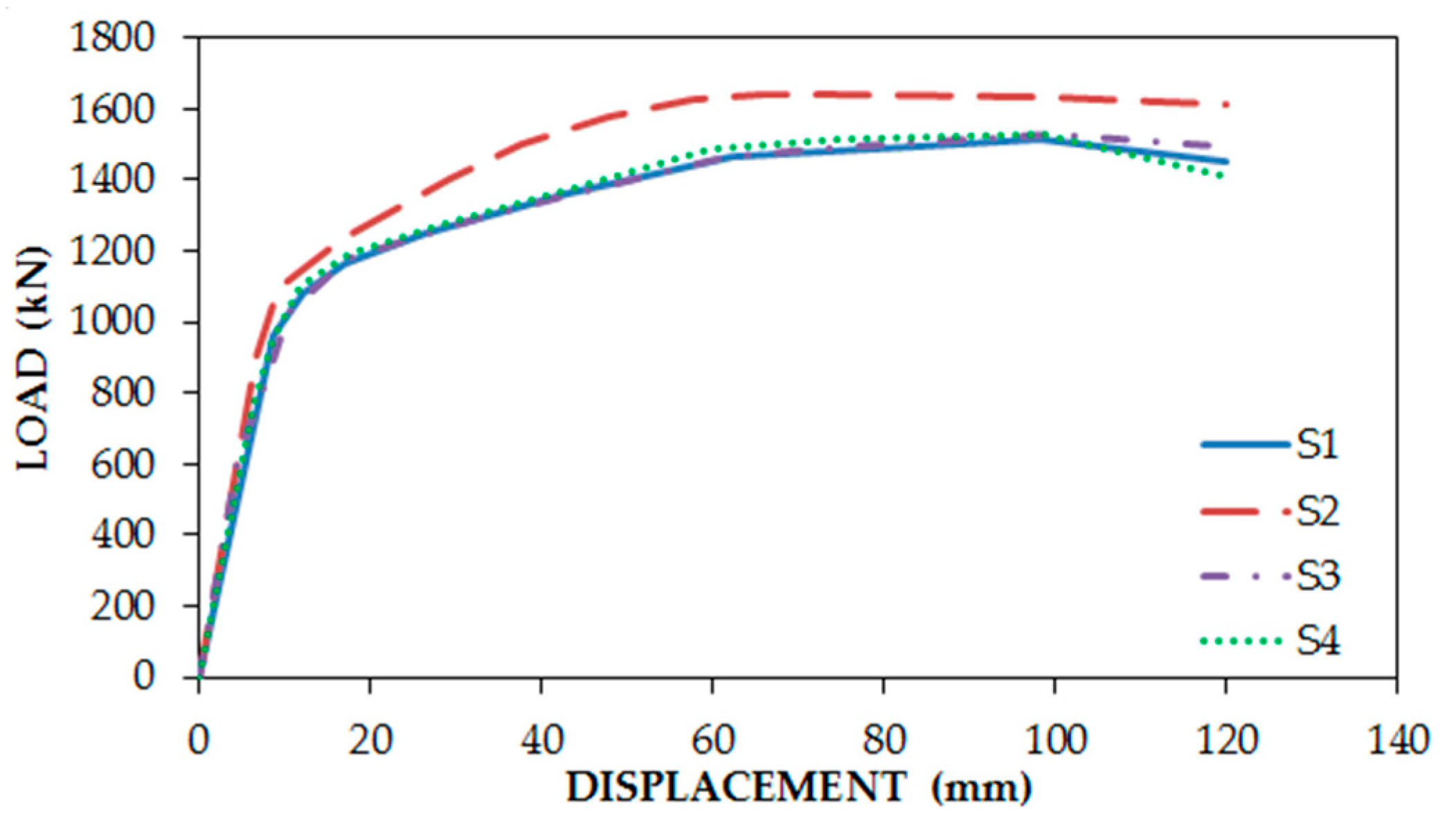
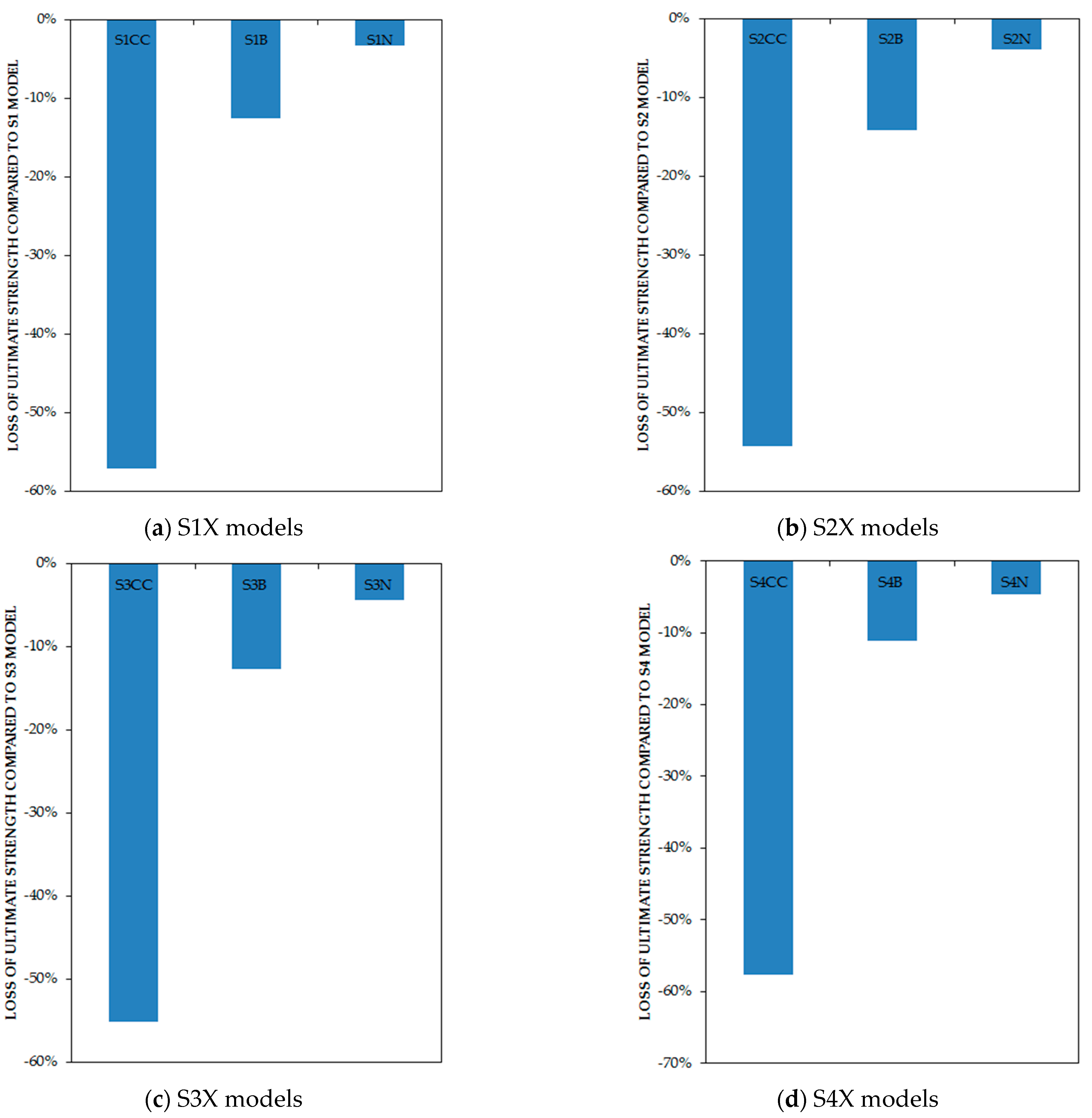
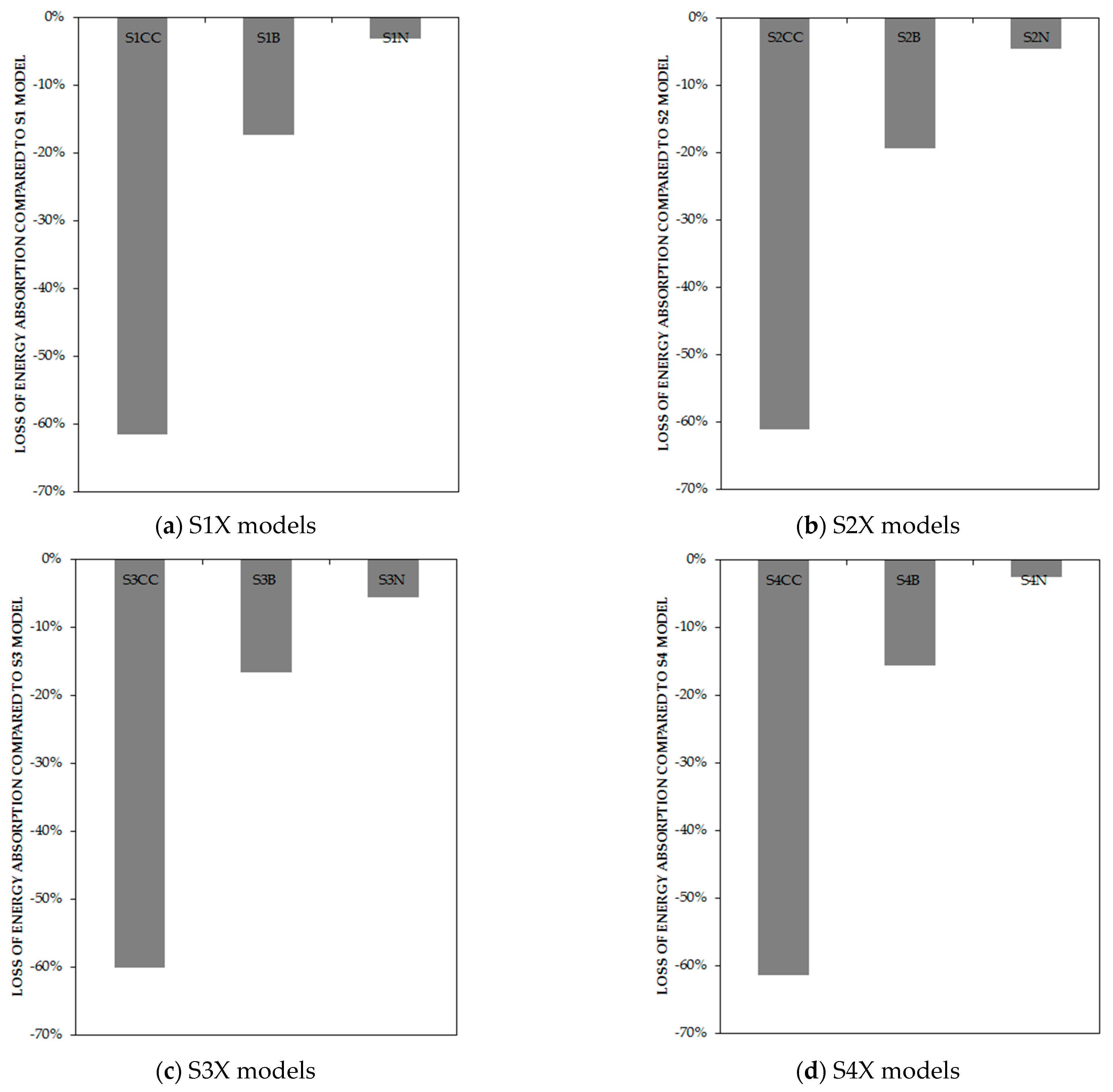
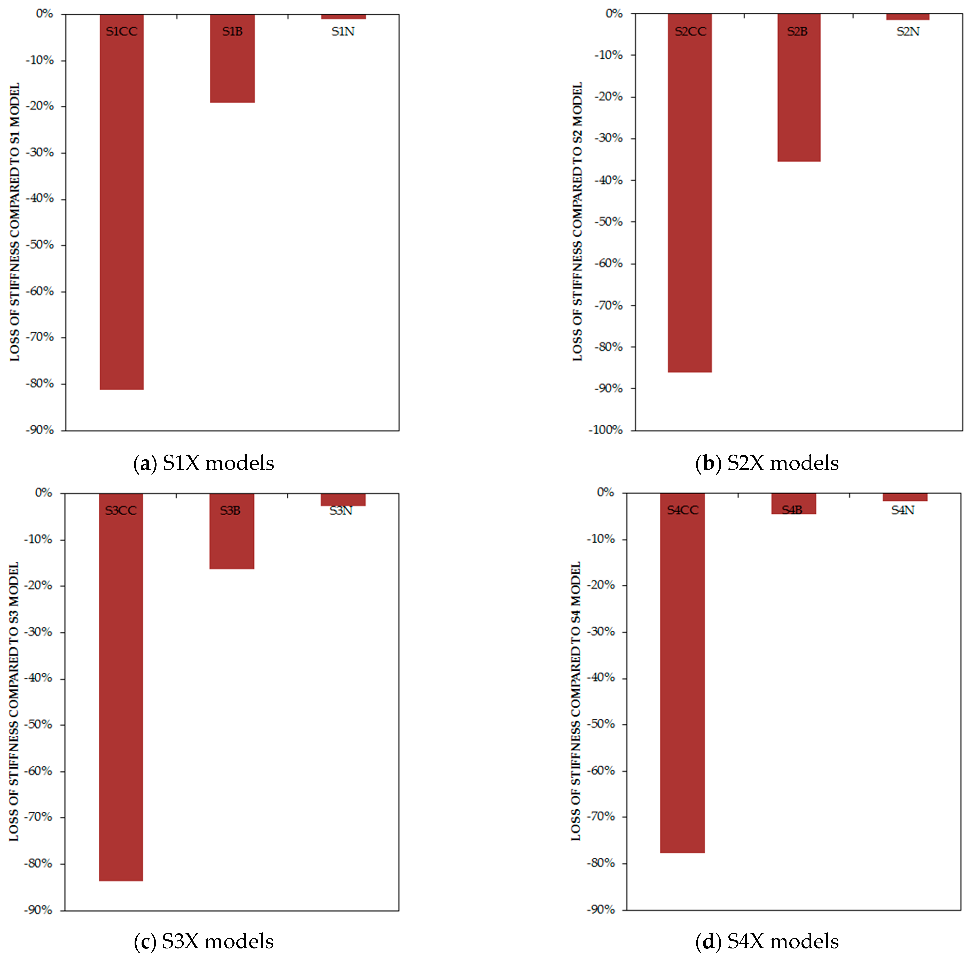
| Model | Ultimate Strength (kN) | Energy Absorption (kN.mm) | Stiffness (kN/mm) |
|---|---|---|---|
| S1 | 1517.48 | 159,684.31 | 112.58 |
| S1CC | 651.383 | 61,517.52 | 21.25 |
| S1B | 1328.06 | 131,938.53 | 91.03 |
| S1N | 1468.47 | 154,808.8 | 111.4 |
| S2 | 1642.51 | 176,135.82 | 137.77 |
| S2CC | 750.877 | 68,435.77 | 19.08 |
| S2B | 1410 | 141,959.05 | 88.89 |
| S2N | 1578.43 | 168,138.92 | 135.51 |
| S3 | 1526.32 | 160,315.21 | 110.5 |
| S3CC | 685.167 | 63,875.76 | 18.15 |
| S3B | 1333.33 | 133,752.2 | 92.38 |
| S3N | 1459.46 | 151,460.3 | 108.28 |
| S4 | 1530.86 | 161,259.91 | 115.91 |
| S4CC | 648 | 62,257.4 | 25.95 |
| S4B | 1359.68 | 136,123.05 | 110.62 |
| S4N | 1460.47 | 157,209.73 | 113.91 |
Publisher’s Note: MDPI stays neutral with regard to jurisdictional claims in published maps and institutional affiliations. |
© 2022 by the authors. Licensee MDPI, Basel, Switzerland. This article is an open access article distributed under the terms and conditions of the Creative Commons Attribution (CC BY) license (https://creativecommons.org/licenses/by/4.0/).
Share and Cite
Paslar, N.; Farzampour, A. Effects of Infill Plate’s Interconnection and Boundary Element Stiffness on Steel Plate Shear Walls’ Seismic Performance. Materials 2022, 15, 5487. https://doi.org/10.3390/ma15165487
Paslar N, Farzampour A. Effects of Infill Plate’s Interconnection and Boundary Element Stiffness on Steel Plate Shear Walls’ Seismic Performance. Materials. 2022; 15(16):5487. https://doi.org/10.3390/ma15165487
Chicago/Turabian StylePaslar, Nima, and Alireza Farzampour. 2022. "Effects of Infill Plate’s Interconnection and Boundary Element Stiffness on Steel Plate Shear Walls’ Seismic Performance" Materials 15, no. 16: 5487. https://doi.org/10.3390/ma15165487