
A Review on Synthetic Fibers for Polymer Matrix Composites: Performance, Failure Modes and Applications


Abstract
:1. Introduction
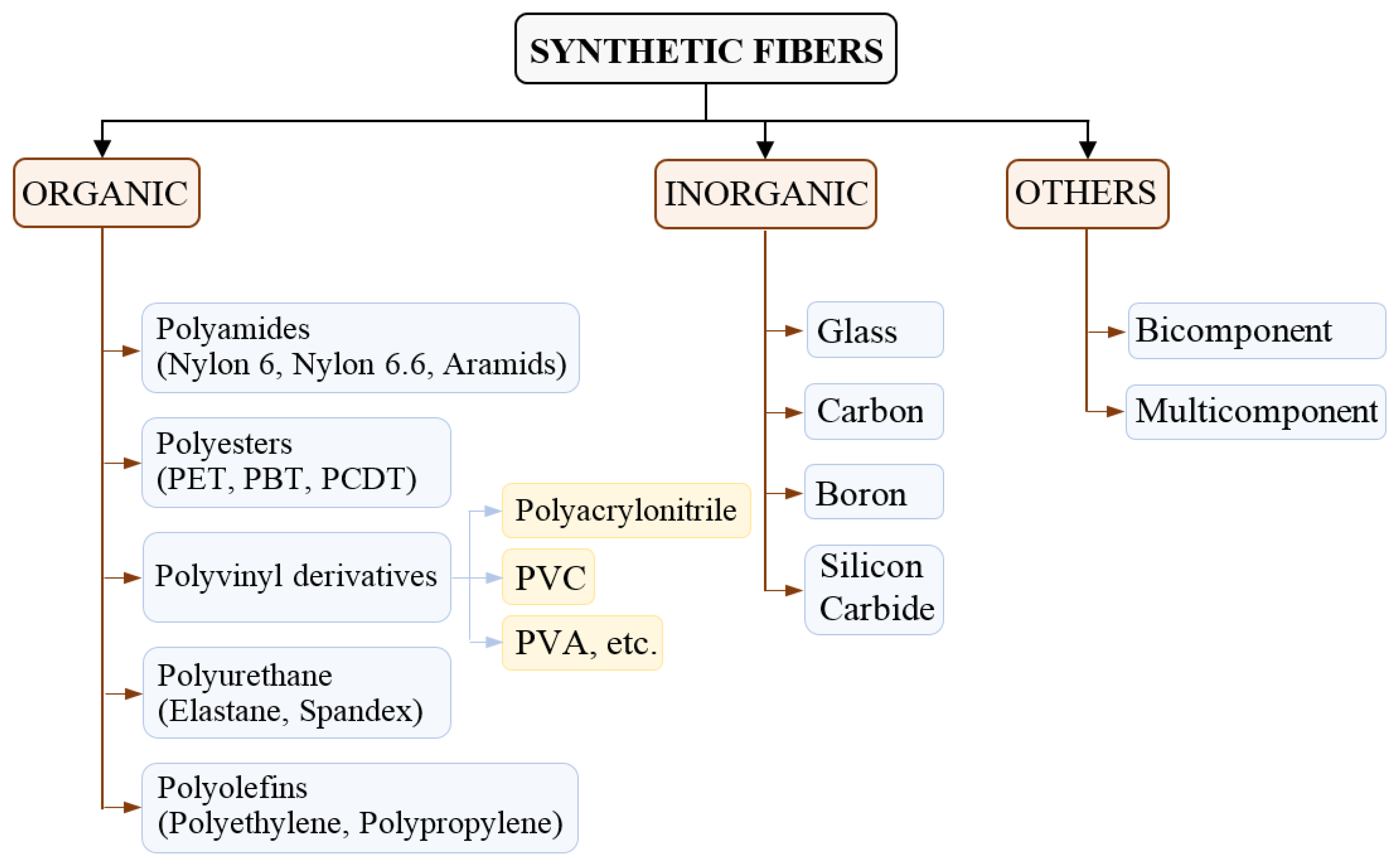
2. Types of Synthetic Fibers
2.1. Organic Fibers
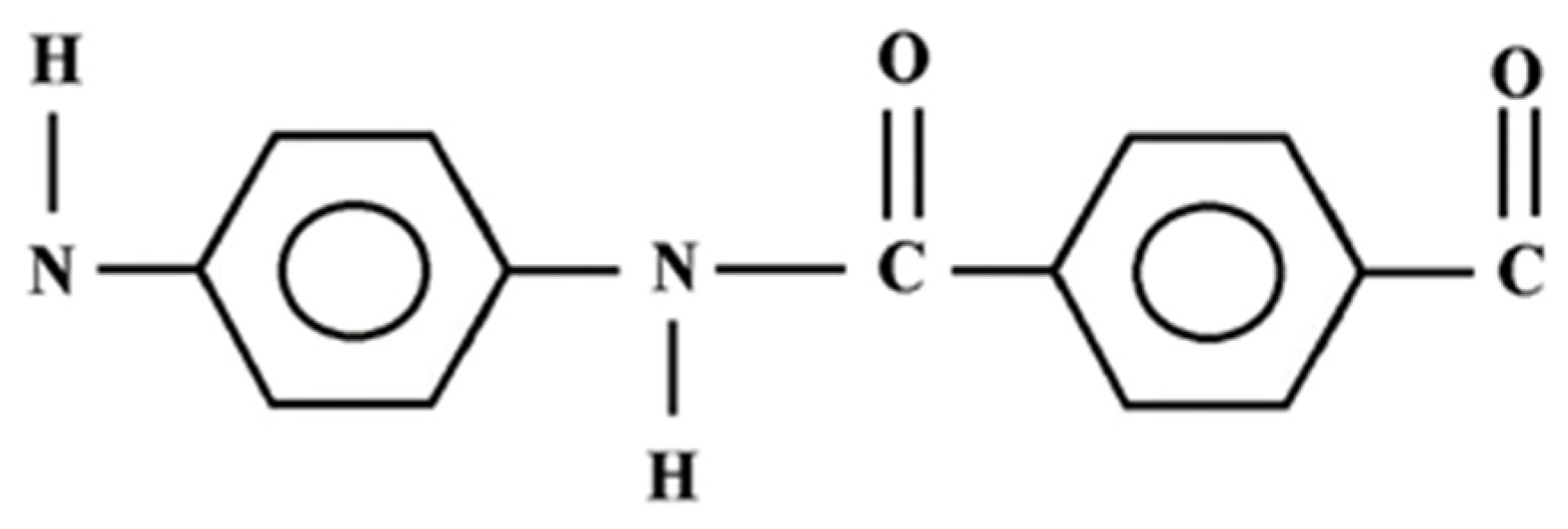
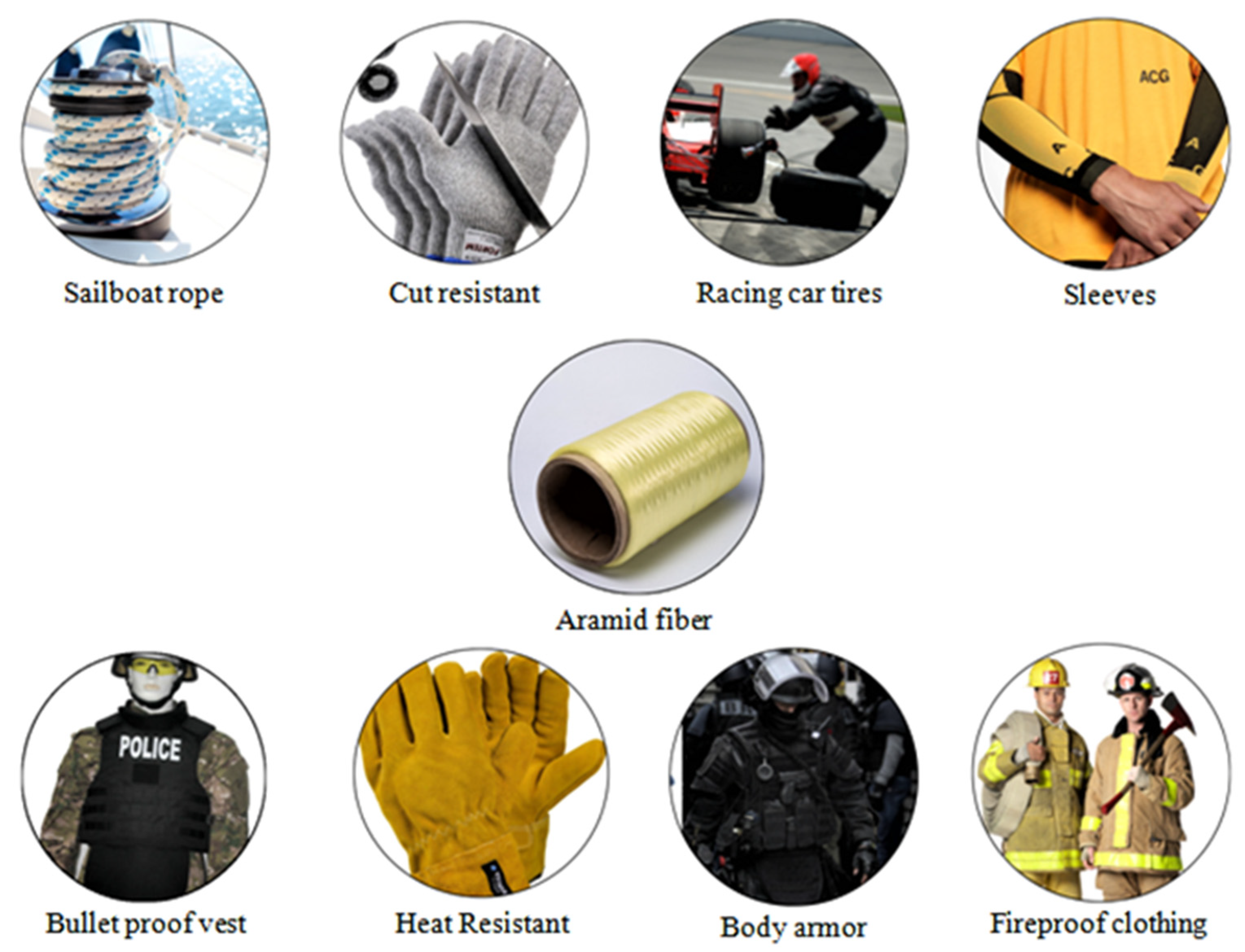
2.1.1. Aramid/Kevlar Fibers
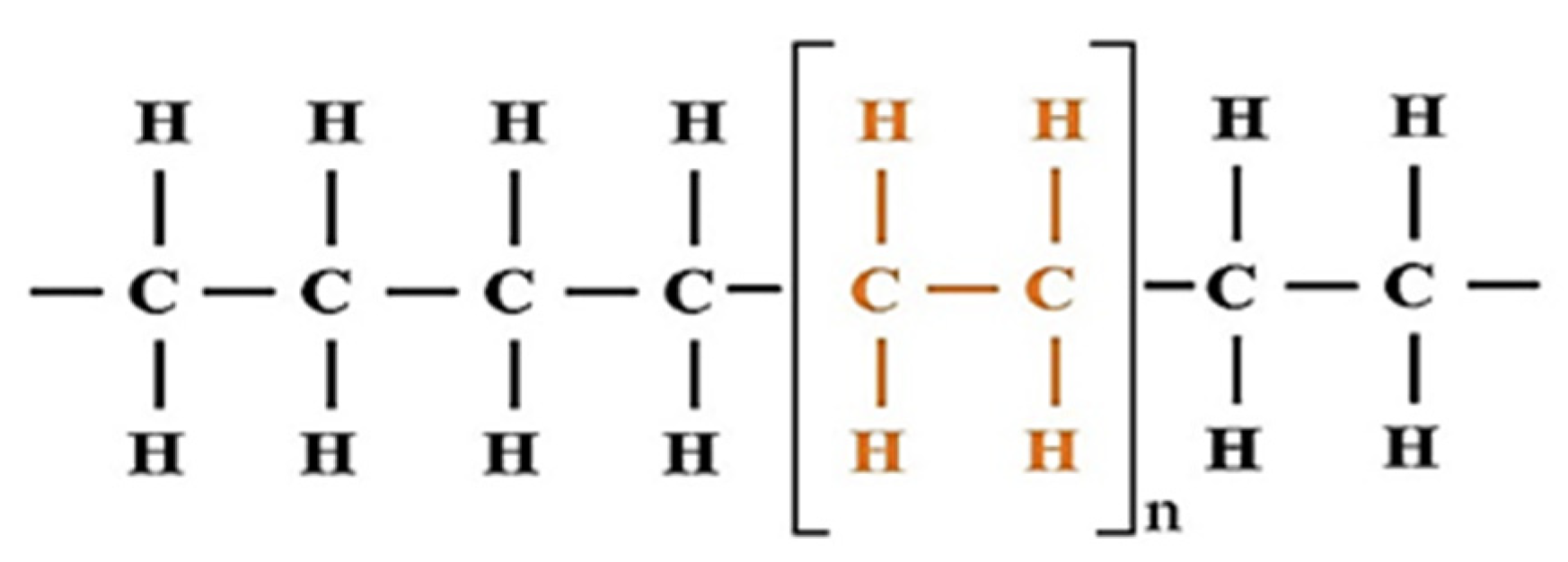
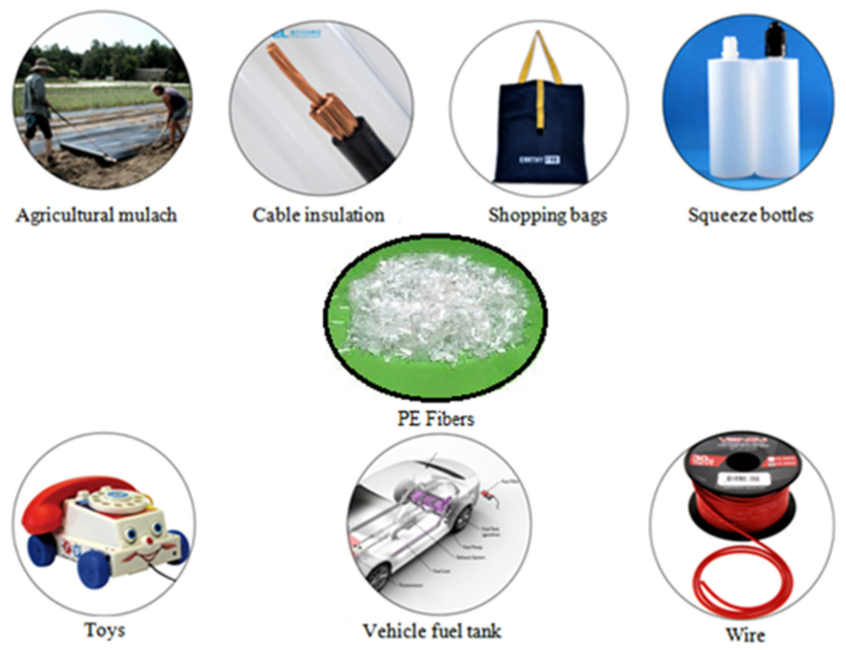
2.1.2. Polyethylene Fibers
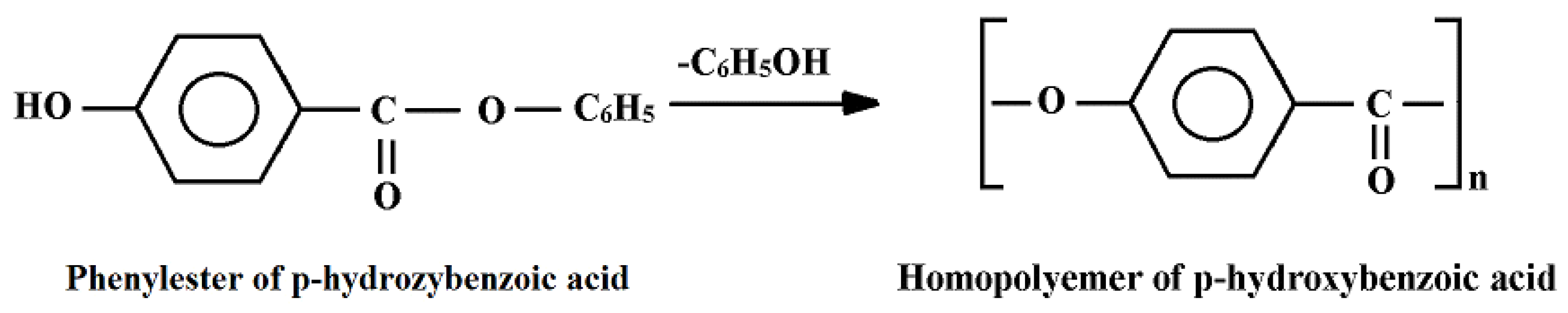
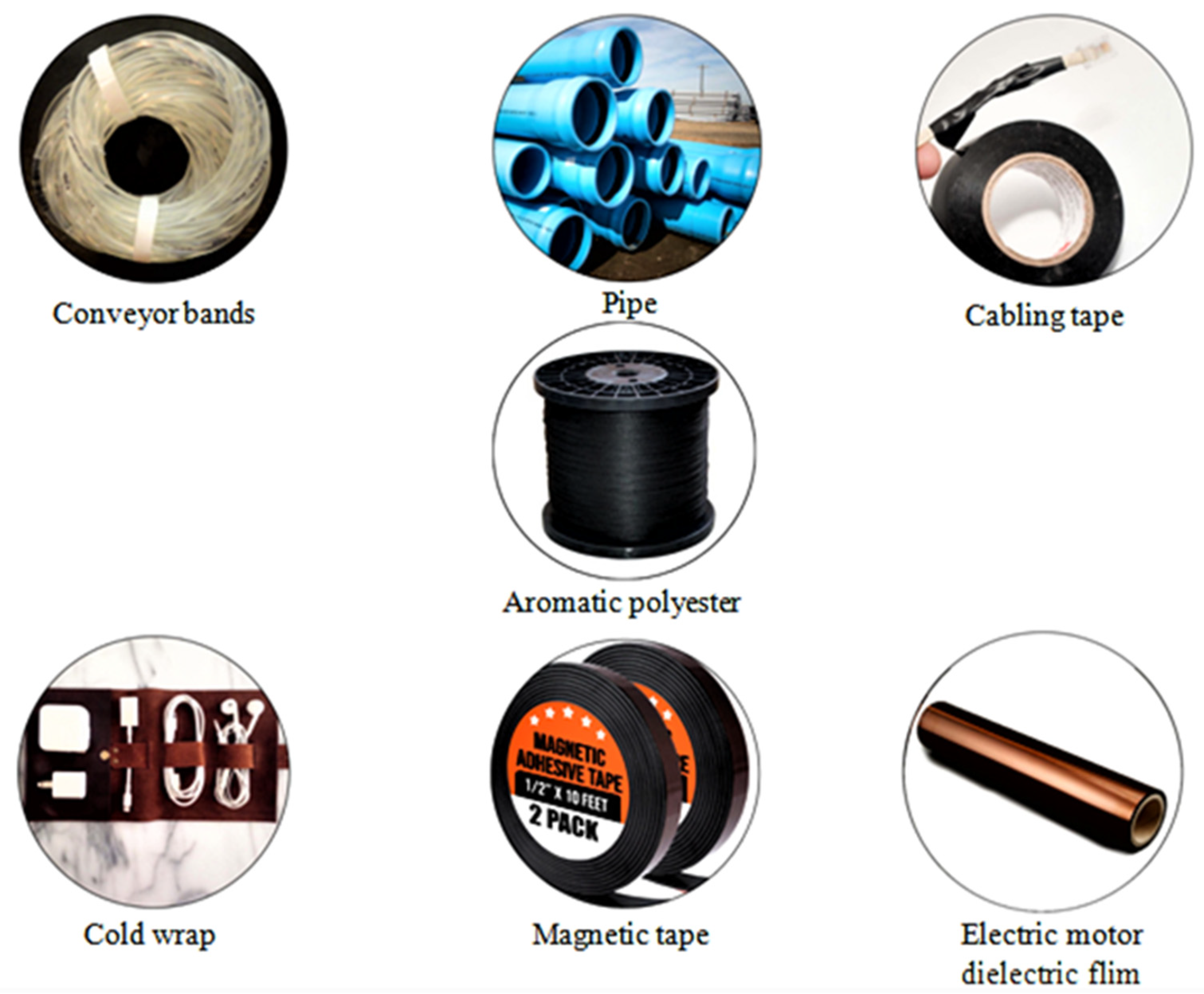
2.1.3. Aromatic Polyester Fibers
2.1.4. Nylon Fibers
2.2. Inorganic Fibers
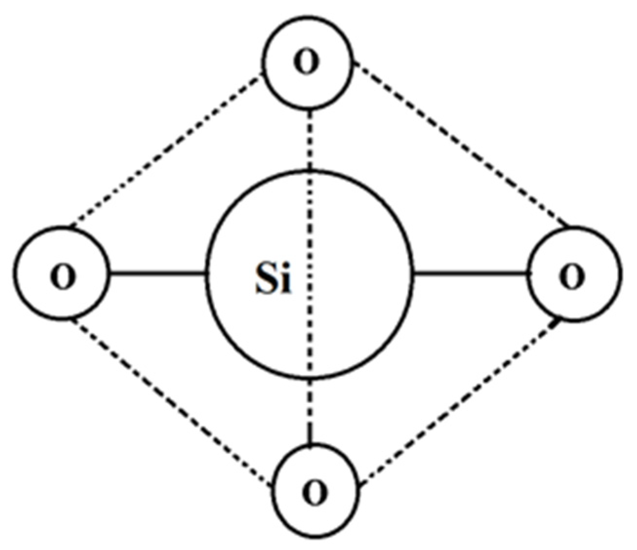
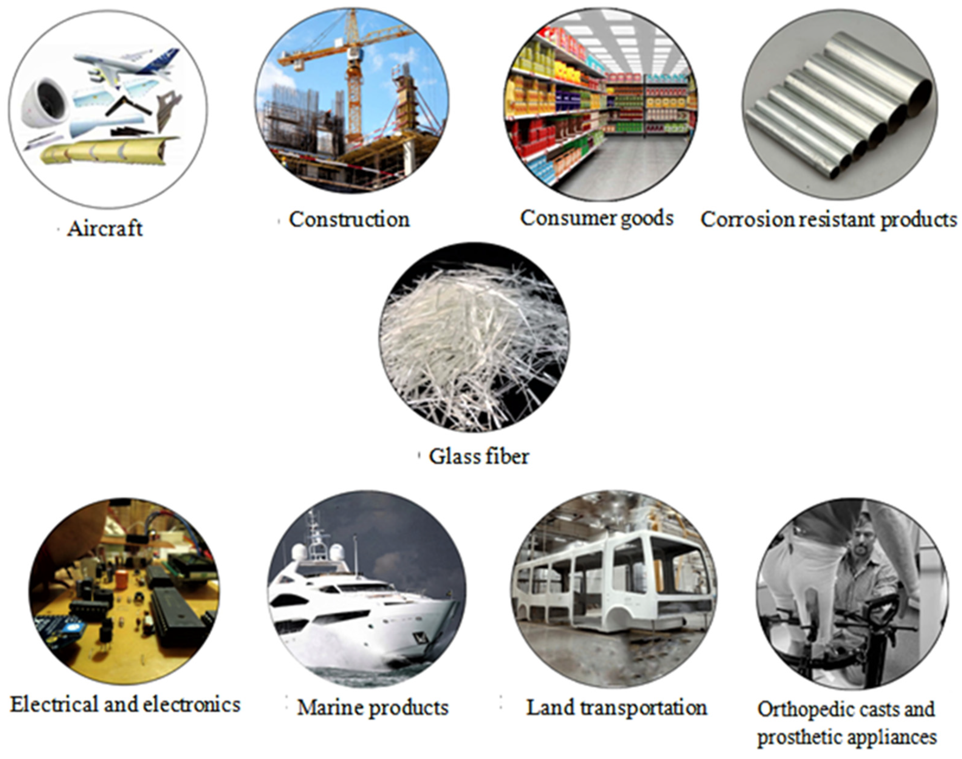
2.2.1. Glass Fibers
- ▪
- A-glass is the most common type of silica glass and is also called soda-lime-silica glass. This type of GF is sensitive to temperature variations, due to the high coefficient of thermal expansion produced by high thermal stresses that can cause yielding.
- ▪
- E-glass is a fungal or bacteria-free fiber that can withstand the main chemical causes, and endures dimensionally steady, even under extreme fluctuations of moisture and heat.
- ▪
- C-glass is practiced for making glass screens or shades lacking corrosion-resistant properties.
- ▪
- AR-glass is produced mainly for coating standard cement weapons. It can resist the alkaline aggregates produced throughout solidification as it contains high zirconium oxide.
- ▪
- S-2-glass is normally used for polymer matrix composites that necessitate improved mechanical characteristics. S-glass fiber is used for high-performance applications.
- ▪
- D-glass is a low dielectric constant glass produced with borosilicate and used in electrical applications.
- ▪
- R-glass is a reinforcement glass made of calcium aluminosilicate used where higher strength and acid corrosion protection are required.
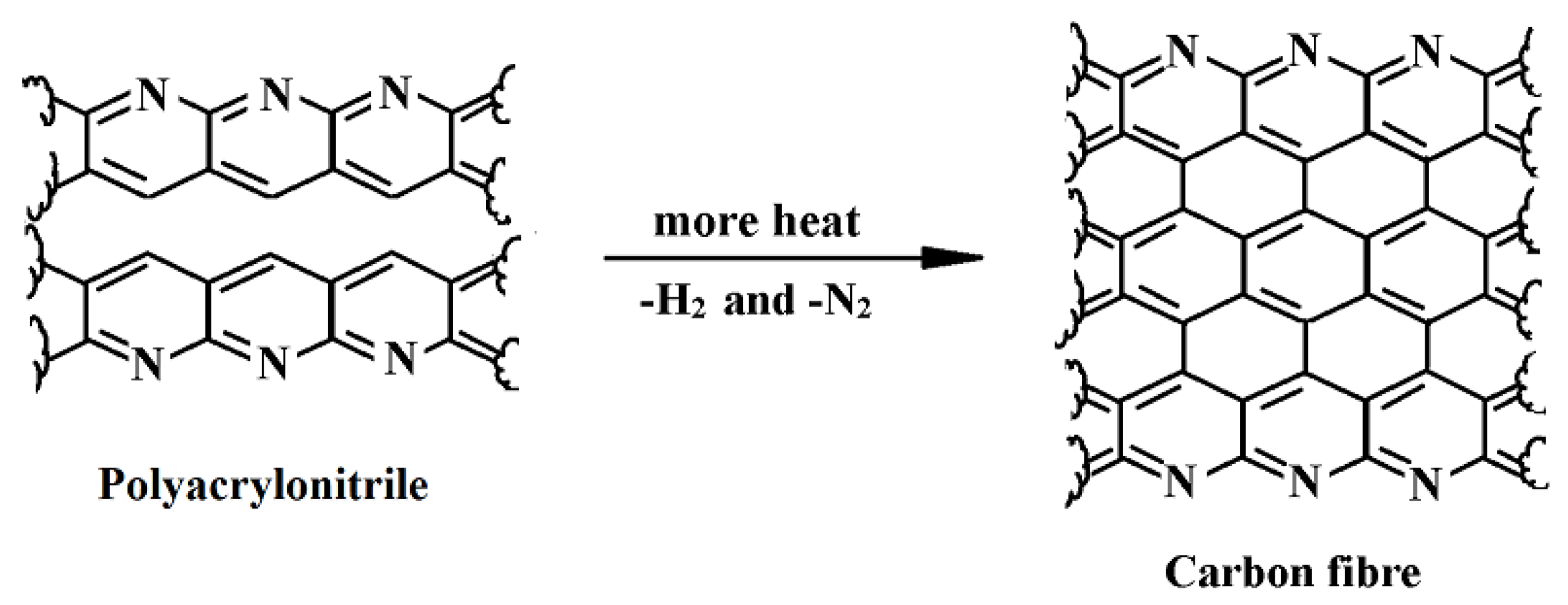
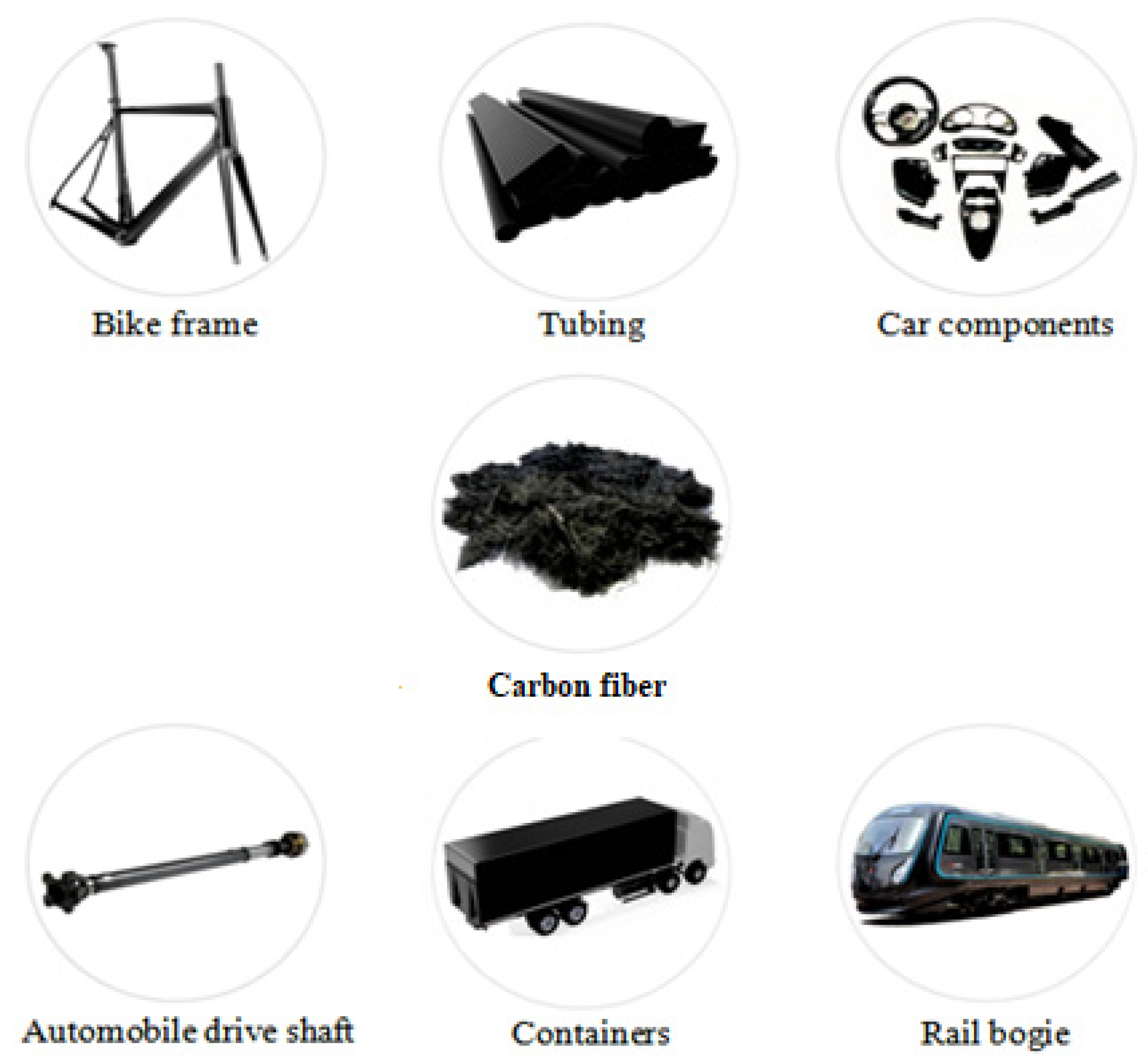
2.2.2. Carbon Fibers
- ▪
- PAN type CF, generated from the carbonization procedure of polyacrylonitrile at a temperature of 1200 °C for several minutes. These fibers have an HTS and HM, being widely used in the aerospace and sports industries [115].
- ▪
- Pitch type CF, generated from the carbonization procedure of oil/coal in a nitrogen environment at a temperature of about 1200 °C. Pitch CF has various characteristics from LM to UHM. Due to this aspect, the fibers are used in stiff and thermally conductive elements [116].
2.2.3. Boron Fibers
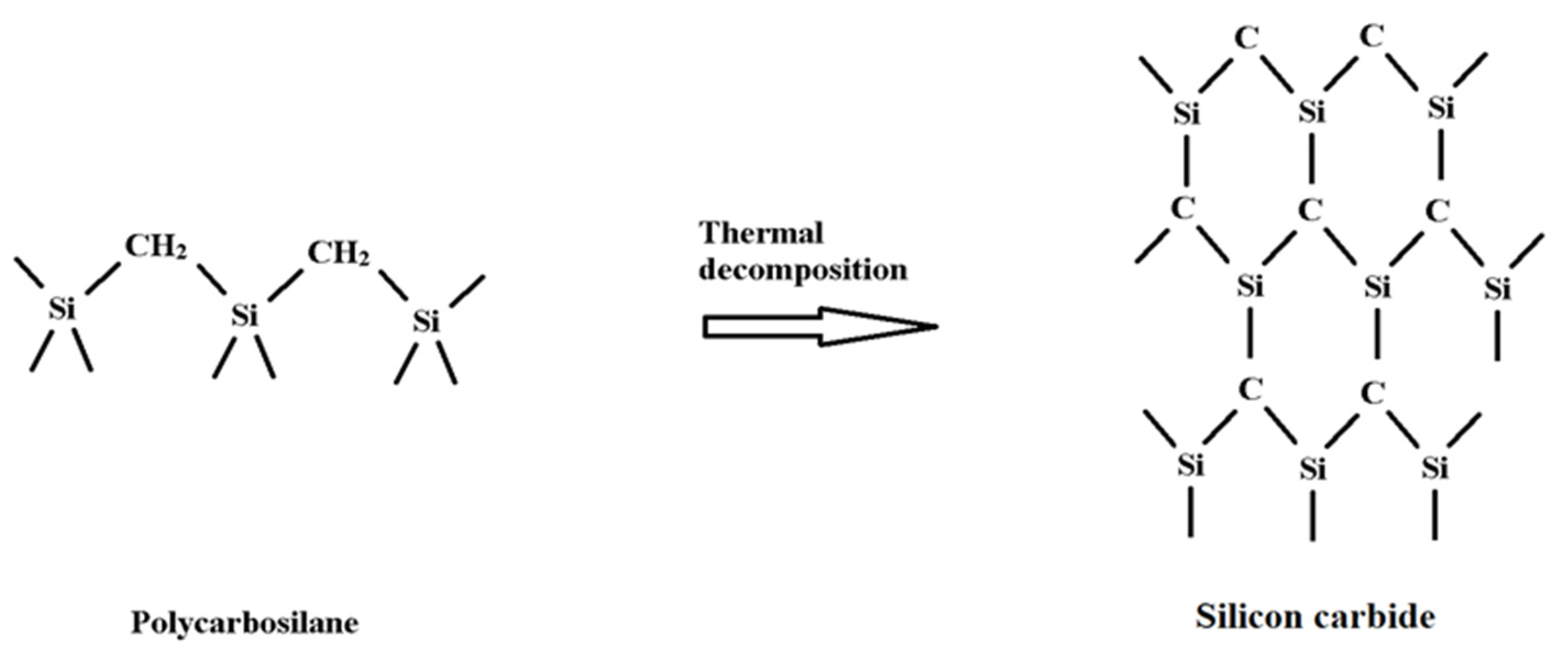
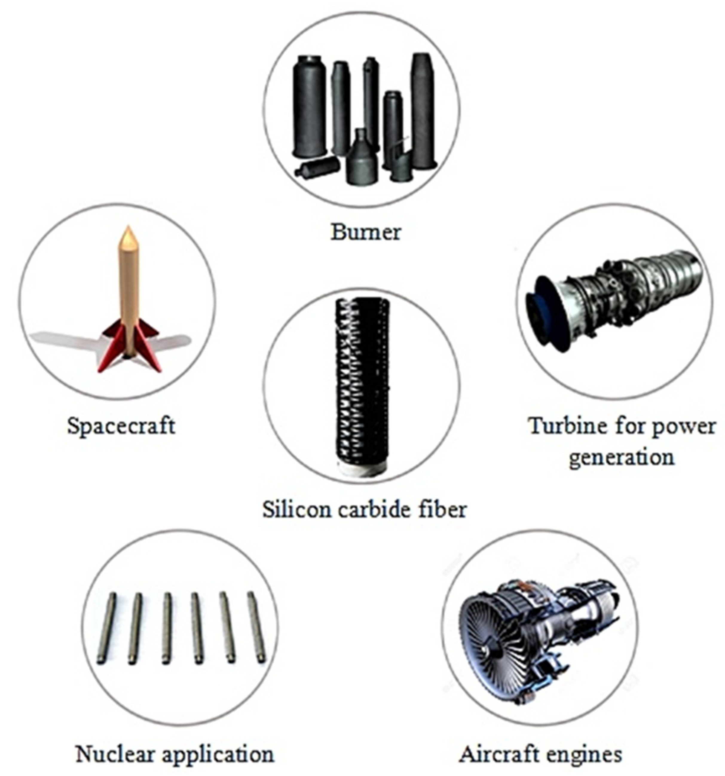
2.2.4. Silica Carbide Fibers
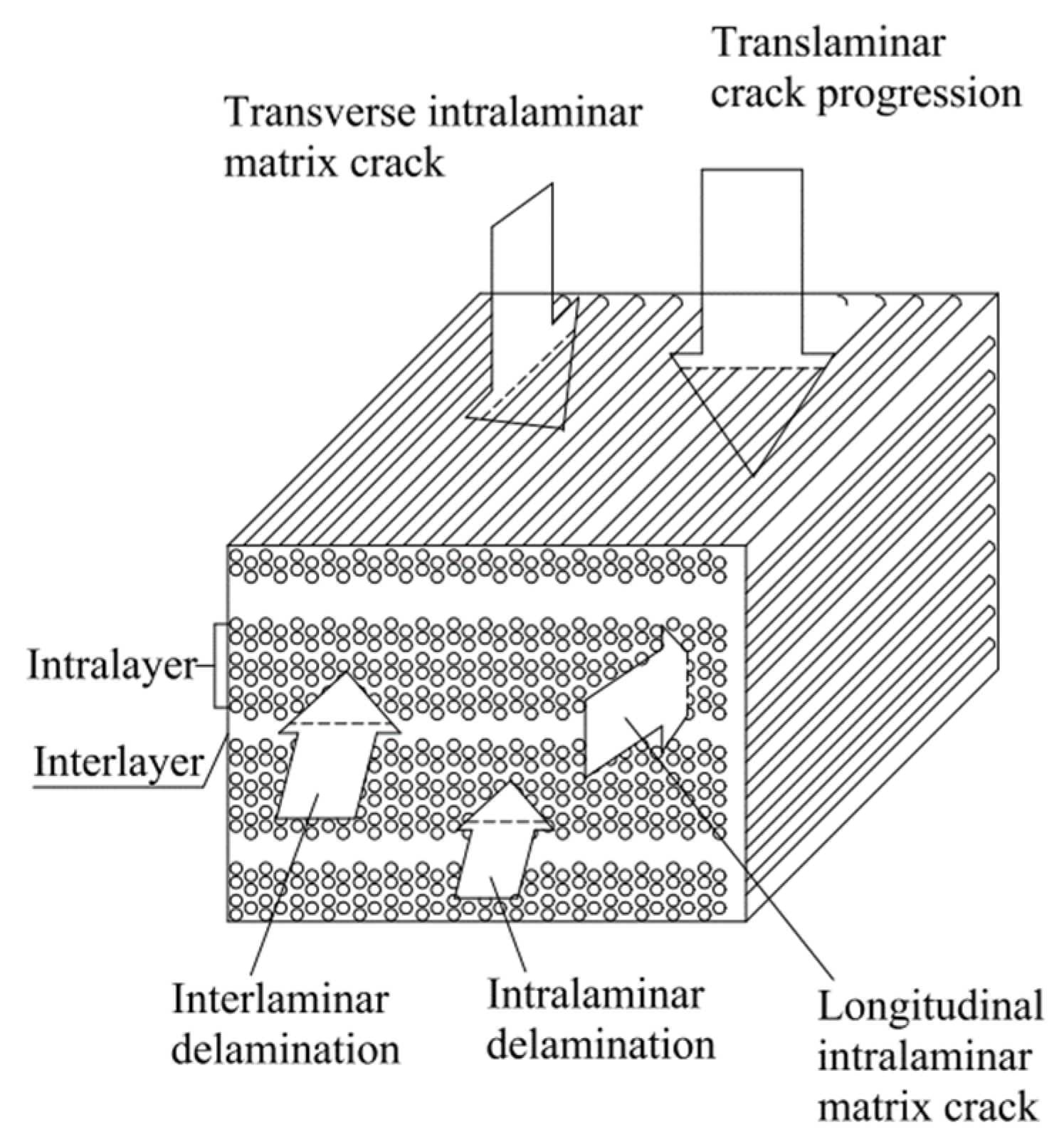
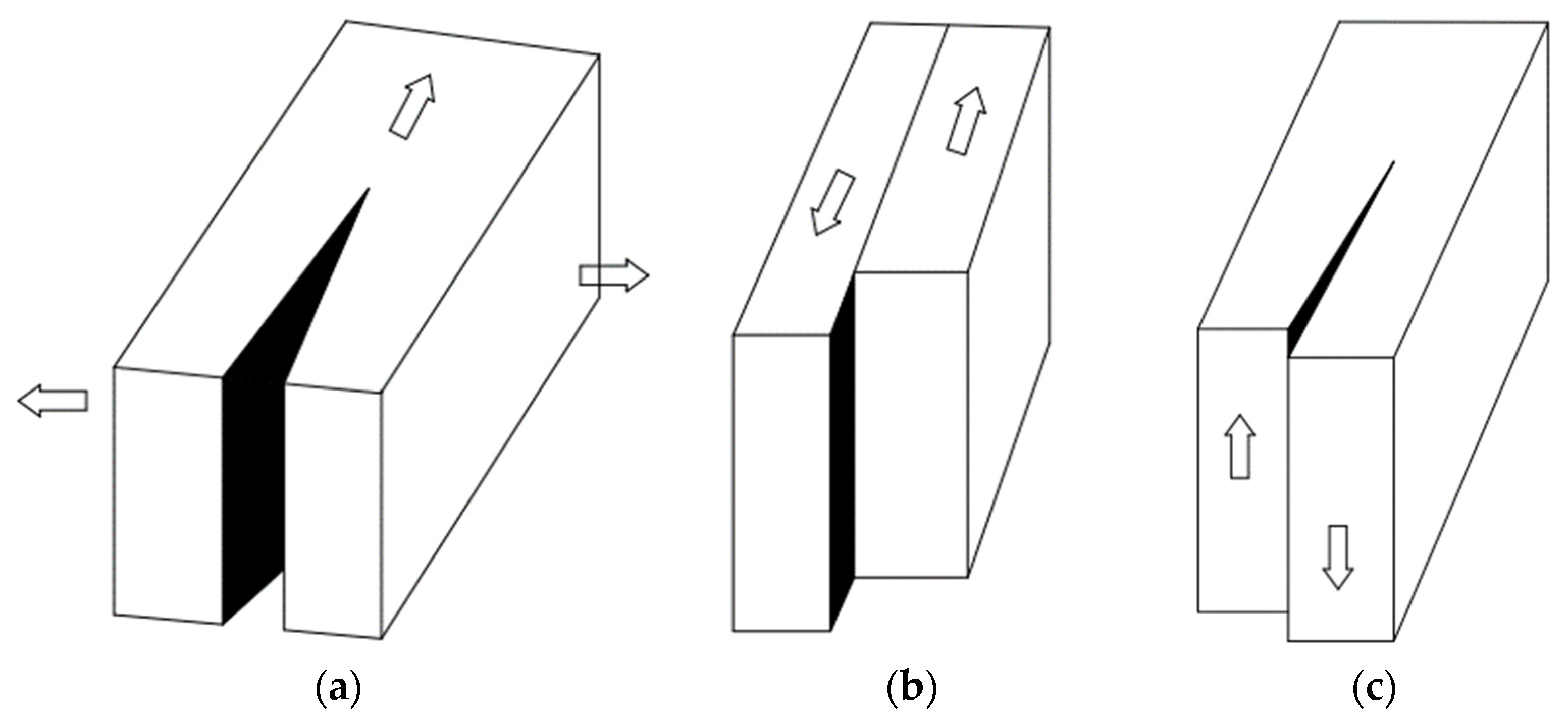
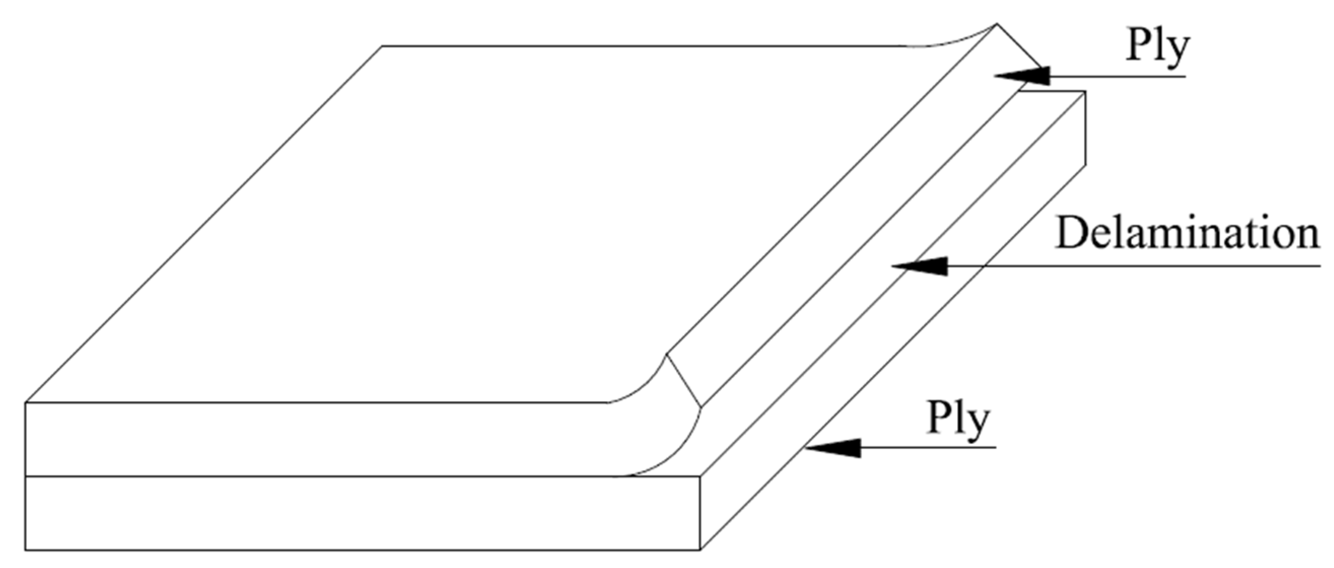
3. Failure Modes in FRP Composites
3.1. Delamination
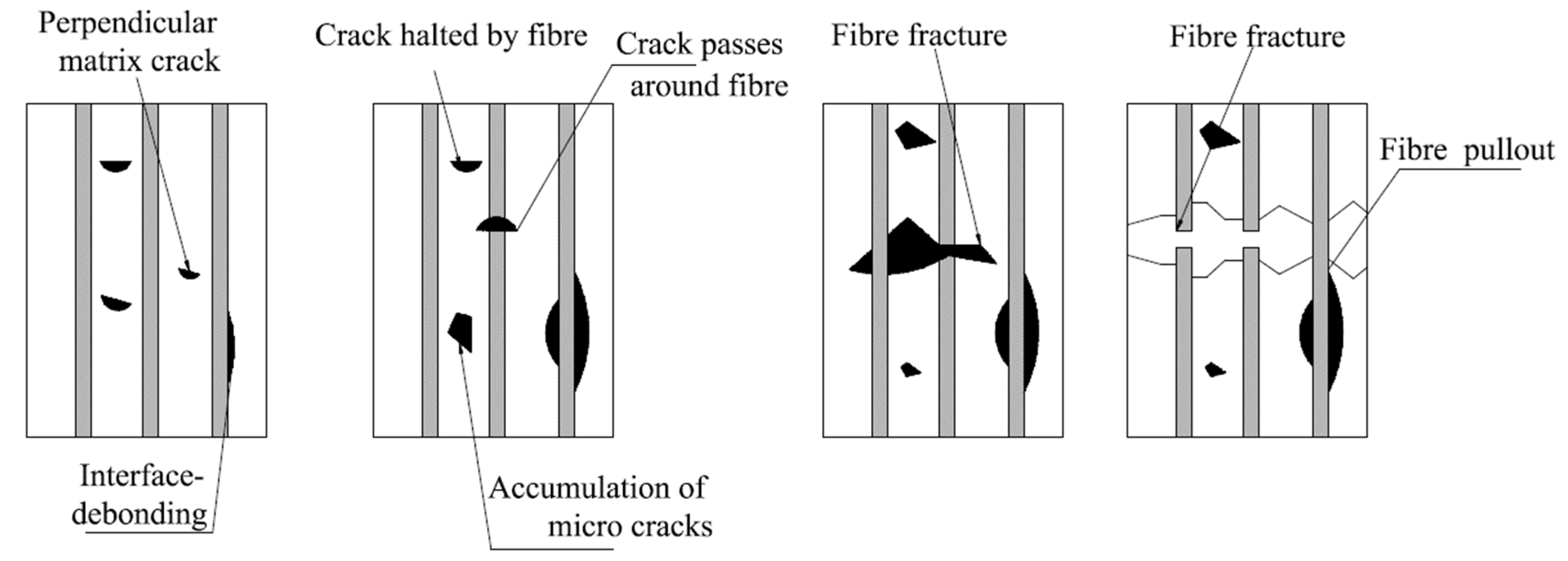
3.2. Fiber Pull-Out and Debonding
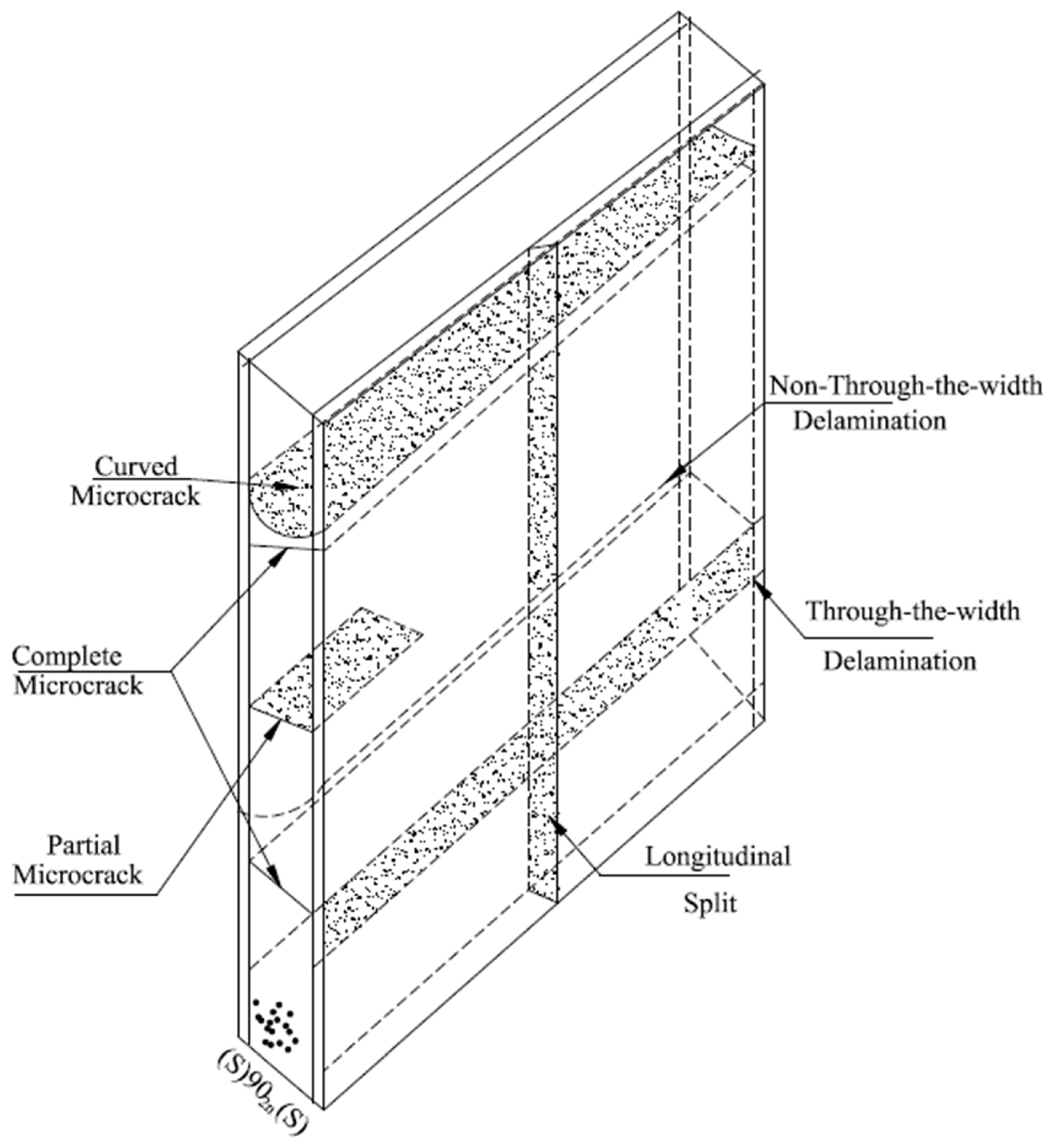
3.3. Microcracking
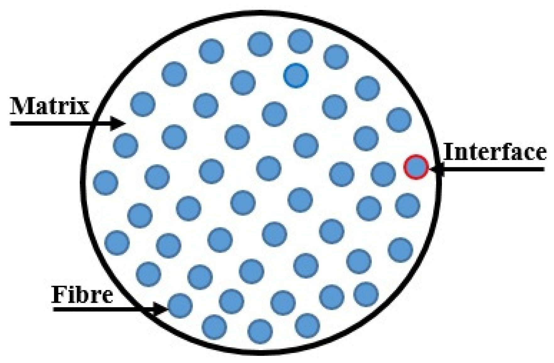
4. Fiber/Matrix Interface and Surface Treatment
4.1. Fiber/Matrix Interface
- -
- Direct methods: Single-fiber pullout tests, Multiple-fiber pullout tests, Fiber fragmentation tests, and Micro-indentation push-in tests.
- -
- Indirect method: Short-beam shear strength test, Inter-laminar shear strength tests.
4.2. Surface Treatment
- ▪
- Chemical modification through treatment, CAs, and functionalization;
- ▪
- Chemical modification through etching;
- ▪
- Chemical modification through grafting;
- ▪
- Physical modification through surface tension and energy compatibilization;
- ▪
- Radio-frequency (RF) sputtering, chemical vapor deposition, physical vapor deposition, and plasma-assisted CVD;
- ▪
- Cold spray for low-temperature polymers;
- ▪
- Electrolytic, electro-less, and dip coatings;
- ▪
- Physicochemical techniques as a combination of these techniques;
- ▪
- Stem cell culture, cloning, and growth on unmodified or modified substrates;
- ▪
- Laser, electron, plasma, infrared, and x-ray irradiation techniques to modify surfaces;
- ▪
- Ultrasound, RF, and microwave sonication;
- ▪
- Surface static charge and conductivity modifications;
- ▪
- Surface roughness, texture, and topography modifications for mechanical adhesion;
- ▪
- Neutron chemical transmutation doping of the reinforcement surface;
- ▪
- Diffusion processes, surface-selective hardening, and softening techniques;
- ▪
- Transverse fibrillation for superior bonding, phase transition modifications, and skinning and cladding;
- ▪
- Preferred polymorphic and allotropic transformations that contribute to strengthening;
- ▪
- Weaving, stitching, knitting, and braiding to improve transverse flow and provide more surface area, wettability, and percolation of the matrix;
- ▪
- Coefficient of thermal expansion matching with the matrix for accommodative interfacial behavior;
- ▪
- Sizing, thermal, and water boiling treatment;
- ▪
- Vacuum and hot vacuum degassing to remove contamination; and
- ▪
- Thermo-oxidative adhesive coatings to improve interfacial thermal stability.
5. Conclusions and Future Directions
Author Contributions
Funding
Institutional Review Board Statement
Informed Consent Statement
Data Availability Statement
Conflicts of Interest
References
- Ahmad, J.; Majdi, A.; Al-Fakih, A.; Deifalla, A.F.; Althoey, F.; El Ouni, M.H.; El-Shorbagy, M.A. Mechanical and Durability Performance of Coconut Fiber Reinforced Concrete: A State-of-the-Art Review. Materials 2022, 15, 3601. [Google Scholar] [CrossRef]
- Andrzejewski, J.; Gapiński, B.; Islam, A.; Szostak, M. The Influence of the Hybridization Process on the Mechanical and Thermal Properties of Polyoxymethylene (POM) Composites with the Use of a Novel Sustainable Reinforcing System Based on Biocarbon and Basalt Fiber (BC/BF). Materials 2020, 13, 3496. [Google Scholar] [CrossRef] [PubMed]
- Olszewski, A.; Kosmela, P.; Mielewczyk-Gryń, A.; Piszczyk, Ł. Bio-Based Polyurethane Composites and Hybrid Composites Containing a New Type of Bio-Polyol and Addition of Natural and Synthetic Fibers. Materials 2020, 13, 2028. [Google Scholar] [CrossRef] [PubMed]
- Camargo, M.M.; Adefrs Taye, E.; Roether, J.A.; Tilahun Redda, D.; Boccaccini, A.R. A Review on Natural Fiber-Reinforced Geopolymer and Cement-Based Composites. Materials 2020, 13, 4603. [Google Scholar] [CrossRef] [PubMed]
- Bhudolia, S.K.; Gohel, G.; Leong, K.F.; Islam, A. Advances in Ultrasonic Welding of Thermoplastic Composites: A Review. Materials 2020, 13, 1284. [Google Scholar] [CrossRef] [Green Version]
- Sujon, A.S.; Islam, A.; Nadimpalli, V.K. Damping and sound absorption properties of polymer matrix composites: A review. Polym. Test. 2021, 104, 107388. [Google Scholar] [CrossRef]
- Kirmasha, Y.K.; Sharba, M.J.; Leman, Z.; Sultan, M.T.H. Mechanical Performance of Unstitched and Silk Fiber-Stitched Woven Kenaf Fiber-Reinforced Epoxy Composites. Materials 2020, 13, 4801. [Google Scholar] [CrossRef]
- Kampa, Ł.; Sadowski, Ł.; Królicka, A. The use of synthetic and natural fibers in epoxy coatings: A comparative mechanical and economic analysis. Int. J. Adhes. Adhes. 2021, 117, 103017. [Google Scholar] [CrossRef]
- Baji, A.; Mai, Y.W.; Du, X.S.; Wong, S.C. Improved Tensile Strength and Ferroelectric Phase Content of Self-Assembled Polyvinylidene Fluoride Fiber Yarns. Macromol. Mater. Eng. 2012, 297, 209–213. [Google Scholar] [CrossRef]
- Li, Y.; Gora, A.; Anariba, F.; Baji, A. Enhanced tensile strength and electrical conductivity of electrospun polyacrylonitrile Yarns via post-treatment. Polym. Compos. 2019, 40, 1702–1707. [Google Scholar] [CrossRef]
- Sahay, R.; Agarwal, K.; Subramani, A.; Raghavan, N.; Budiman, A.S.; Baji, A. Helicoidally Arranged Polyacrylonitrile Fiber-Reinforced Strong and Impact-Resistant Thin Polyvinyl Alcohol Film Enabled by Electrospinning-Based Additive Manufacturing. Polymers 2020, 12, 2376. [Google Scholar] [CrossRef] [PubMed]
- Watts, M.J.; Amin, A.; Bernard, E.S.; Gilbert, R.I.; Facconi, L. Early age bond stress-slip behaviour of macro-synthetic fibre reinforced concrete. Constr. Build. Mater. 2021, 301, 124097. [Google Scholar] [CrossRef]
- Agarwal, K.; Sahay, R.; Baji, A. Tensile Properties of Composite Reinforced with Three-Dimensional Printed Fibers. Polymers 2020, 12, 1089. [Google Scholar] [CrossRef]
- Rajak, D.K.; Pagar, D.D.; Menezes, P.L.; Linul, E. Fiber-Reinforced Polymer Composites: Manufacturing, Properties, and Applications. Polymers 2019, 11, 1667. [Google Scholar] [CrossRef] [PubMed] [Green Version]
- Mohan, K.A.; Dimple, A.N.; Ashokavel, S.; Boopathi, M. Numerical investigation of mechanical properties of hybrid fiber reinforced polymer composites. Mater. Today Proc. 2021, 52, 2255–2263. [Google Scholar] [CrossRef]
- Agarwal, K.; Sahay, R.; Baji, A.; Budiman, A.S. Impact Resistant and Tough Helicoidally Aligned Ribbon Reinforced Composite with Tunable Mechanical Properties via Integrated Additive Manufacturing Methodologies. ACS Appl. Polym. Mater. 2020, 2, 3491–3504. [Google Scholar] [CrossRef]
- Siamardi, K.; Shabani, S. Evaluation the effect of micro-synthetic fiber on mechanical and freeze-thaw behavior of non-air-entrained roller compacted concrete pavement using response surface methodology. Constr. Build. Mater. 2021, 295, 123628. [Google Scholar] [CrossRef]
- Manteghi, S.; Sarwar, A.; Fawaz, Z.; Zdero, R.; Bougherara, H. Mechanical characterization of the static and fatigue compressive properties of a new glass/flax/epoxy composite material using digital image correlation, thermographic stress analysis, and conventional mechanical testing. Mater. Sci. Eng. C 2019, 99, 940–950. [Google Scholar] [CrossRef]
- Yoo, D.Y.; Kim, S.; Park, G.J.; Park, J.J. Residual performance of HPFRCC exposed to fire—Effects of matrix strength, synthetic fiber, and fire duration. Constr. Build. Mater. 2020, 241, 118038. [Google Scholar] [CrossRef]
- Di Maida, P.; Sciancalepore, C.; Radi, E.; Bondioli, F. Effects of nano-silica treatment on the flexural post cracking behaviour of polypropylene macro-synthetic fibre reinforced concrete. Mech. Res. Commun. 2018, 88, 12–18. [Google Scholar] [CrossRef]
- Begum, S.; Fawzia, S.; Hashmi, M.S.J. Polymer matrix composite with natural and synthetic fibres. Adv. Mater. Process. Technol. 2020, 6, 547–564. [Google Scholar] [CrossRef]
- Nandana, B.; Kundu, S.C. Electrospinning: A fascinating fiber fabrication technique. Biotechnol. Adv. 2010, 28, 325–347. [Google Scholar]
- Won, J.P.; Lim, D.H.; Park, C.G. Bond behaviour and flexural performance of structural synthetic fibre-reinforced concrete. Mag. Concr. Res. 2006, 58, 401–410. [Google Scholar] [CrossRef]
- Camille, C.; Kahagala Hewage, D.; Mirza, O.; Mashiri, F.; Kirkland, B.; Clarke, T. Performance behaviour of macro-synthetic fibre reinforced concrete subjected to static and dynamic loadings for sleeper applications. Constr. Build. Mater. 2020, 270, 121469. [Google Scholar] [CrossRef]
- Hagewood, J. Technologies for the manufacture of synthetic polymer fibers. In Advances in Filament Yarn Spinning of Textiles and Polymers; Woodhead Publishing: Thorston, UK, 2014; pp. 48–71. [Google Scholar]
- Hluzek, R.; Trejbal, J.; Nezerka, V.; Demo, P.; Prosek, Z.; Tesarek, P. Improvement of bonding between synthetic fibers and a cementitious matrix using recycled concrete powder and plasma treatment: From a single fiber to FRC. Eur. J. Environ. Civ. Eng. 2020, 26, 3880–3897. [Google Scholar] [CrossRef]
- Babafemi, A.J.; Du Plessis, A.; Boshoff, W.P. Pull-out creep mechanism of synthetic macro fibres under a sustained load. Constr. Build. Mater. 2018, 174, 466–473. [Google Scholar] [CrossRef]
- Shrivastava, A. 2—Polymerization. In Introduction to Plastics Engineering; William Andrew Publishing: Norwich, NY, USA, 2018; pp. 17–48. [Google Scholar] [CrossRef]
- Warheit, D.B.; Hart, G.A.; Hesterberg, T.W.; Collins, J.J.; Dyer, W.M.; Swaen, G.M.H.; Castranova, V.; Soiefer, A.I.; Kennedy, G.L. Potential Pulmonary Effects of Man-Made Organic Fiber (MMOF) Dusts. Crit. Rev. Toxicol. 2001, 31, 697–736. [Google Scholar] [CrossRef]
- Goh, G.D.; Yap, Y.L.; Agarwala, S.; Yeong, W.Y. Recent Progress in Additive Manufacturing of Fiber Reinforced Polymer Composite. Adv. Mater. Technol. 2018, 4, 1800271. [Google Scholar] [CrossRef] [Green Version]
- Rajesh, S.; Vijayaramnath, B.; Elanchezhian, C.; Vivek, S.; Prasadh, M.H.; Kesavan, M. Experimental Investigation of Tensile and Impact Behavior of Aramid-Natural Fiber Composite. Mater. Today Proc. 2019, 16, 699–705. [Google Scholar] [CrossRef]
- Bazan, P.; Nosal, P.; Wierzbicka-Miernik, A.; Kuciel, S. A novel hybrid composites based on biopolyamide 10.10 with basalt/aramid fibers: Mechanical and thermal investigation. Compos. Part B 2021, 223, 109125. [Google Scholar] [CrossRef]
- Downing, J.W.; Newell, J.A. Characterization of structural changes in thermally enhanced Kevlar-29 fiber. J. Appl. Polym. Sci. 2003, 91, 417–424. [Google Scholar] [CrossRef]
- Yuan, W.; Li, Y.; Zhao, J. Mechanical properties of a novel Tri-directional carbon-flax-aramid fiber reinforced composite. Compos. Sci. Technol. 2021, 213, 108923. [Google Scholar] [CrossRef]
- Louwsma, J.; Carvalho, A.; Lutz, J.-F.; Joly, S.; Chan-Seng, D. Adsorption of phenylalanine-rich sequence-defined oligomers onto Kevlar fibers for fiber-reinforced polyolefin composite materials. Polymer 2021, 217, 123465. [Google Scholar] [CrossRef]
- Şahin, K.; Clawson, J.K.; Singletary, J.; Chasiotis, I. Shear strength of homopolymer and copolymer aramid fibers. Polymer 2019, 186, 122034. [Google Scholar] [CrossRef]
- Sabu, T.; Jiji, A.; Ajithkumar, M.P.; Asha, K. Composite Materials, In Ullmann’s Encyclopedia of Industrial Chemistry; Wiley: Hoboken, NJ, USA, 2016; pp. 1–44. [Google Scholar]
- Norwood, L.S.; Marchant, A. Recent Developments in Polyester Matrices and Reinforcements for Marine Applications. In Particular Polyester/Kevlar Composites, Polyester Matrices and Reinforcements for Marine Applications; Marshall, I.H., Ed.; Composite Structures © Applied Science Publishers Ltd.: Dordecht, The Netherlands, 1981. [Google Scholar]
- Jassal, M.; Agrawal, A.K.; Gupta, D.; Panwar, K. Aramid Fibers. In Handbook of Fibrous Materials; Wiley: Hoboken, NJ, USA, 2020; pp. 207–231. [Google Scholar]
- Zhao, Y.; Li, X.; Shen, J.; Gao, C.; Van der Bruggen, B. The potential of Kevlar aramid nanofiber composite membranes. J. Mater. Chem. A 2020, 8, 7548–7568. [Google Scholar] [CrossRef]
- Gao, J.; Yang, X.; Guo, J.; Huang, J. Hyperelastic mechanical properties of chopped aramid fiber-reinforced rubber composite under finite strain. Compos. Struct. 2020, 243, 112187. [Google Scholar] [CrossRef]
- Yeung, K.H.; Rao, K.P. Mechanical Properties of Kevlar-49 Fibre Reinforced Thermoplastic Composites. Polym. Polym. Compos. 2012, 20, 411–424. [Google Scholar] [CrossRef]
- Arvinte, C.; Sandu, A.V.; Burduhos-Nergis, D.D.; Bernevig Sava, M.A.; Bejinariu, C. Technical requirements and materials used in firefighters gloves manufacturing. IOP Conf. Ser. Mater. Sci. Eng. 2019, 572, 012070. [Google Scholar] [CrossRef] [Green Version]
- El-Morsy, M.A. A simulation study on investigation the optical and structural properties of polyethylene fiber. Results Phys. 2020, 18, 103230. [Google Scholar] [CrossRef]
- Dun, M.; Fu, H.; Hao, J.; Shan, W.; Wang, W. Tailoring flexible interphases in bamboo fiber-reinforced linear low-density polyethylene composites. Compos. Part A 2021, 150, 106606. [Google Scholar] [CrossRef]
- Roedel, M.J. The Molecular Structure of Polyethylene. I. Chain Branching in Polyethylene during Polymerization. J. Am. Chem. Soc. 1953, 75, 6110–6112. [Google Scholar] [CrossRef]
- Zhang, Q.; Liu, Z.; Qin, Z.; Yan, R.; Jia, L. Characterization of macroscopic impact-resistant behavior of shear thickening fluid impregnated ultra-high molecular weight polyethylene fiber flexible composites. Compos. Commun. 2021, 25, 100756. [Google Scholar] [CrossRef]
- Peacock, A. Handbook of Polyethylene: Structures: Properties, and Applications; CRC Press: Boca Raton, FL, USA, 2000. [Google Scholar]
- Liu, T.; Bai, R.; Chen, Z.; Li, Y.; Yang, Y. Tailoring of polyethylene fiber surface by coating silane coupling agent for strain hardening cementitious composite. Constr. Build. Mater. 2021, 278, 122263. [Google Scholar] [CrossRef]
- Choi, H.-J.; Yoo, D.-Y.; Park, G.-J.; Park, J.-J. Photocatalytic high-performance fiber-reinforced cement composites with white Portland cement, titanium dioxide, and surface treated polyethylene fibers. J. Mater. Res. Technol. 2021, 15, 785–800. [Google Scholar] [CrossRef]
- Jegatheesan, N.; Rengarasu, T.M.; Bandara, W.M.K.R.T.W. Mechanical properties of modified hot mix asphalt containing polyethylene terephthalate fibers as binder additive and carbonized wood particles as fine aggregate replacement. Asian Transp. Stud. 2020, 6, 100029. [Google Scholar] [CrossRef]
- Kasirajan, S.; Ngouajio, M. Polyethylene and biodegradable mulches for agricultural applications: A review. Agron. Sustain. Dev. 2012, 32, 501–529. [Google Scholar] [CrossRef]
- Le, D.K.; Ng, G.N.; Koh, H.W.; Zhang, X.; Thai, Q.B.; Phan-Thien, N.; Duong, H.M. Methyltrimethoxysilane-coated recycled polyethylene terephthalate aerogels for oil spill cleaning applications. Mater. Chem. Phys. 2019, 239, 122064. [Google Scholar] [CrossRef]
- Vinoth, A.; Datta, S. Design of the ultrahigh molecular weight polyethylene composites with multiple nanoparticles: An artificial intelligence approach. J. Compos. Mater. 2019, 54, 179–192. [Google Scholar] [CrossRef]
- Xia, L.; Wu, H.; Qiu, G. Shape memory behavior of carbon nanotube-reinforced trans-1,4-polyisoprene and low-density polyethylene composites. Polym. Adv. Technol. 2019, 31, 107–113. [Google Scholar] [CrossRef]
- Peng, B.; Jiang, Y.; Zhu, A. A novel modification of carbon nanotubes for improving the electrical and mechanical properties of polyethylene composites. Polym. Test. 2019, 74, 72–76. [Google Scholar] [CrossRef]
- Ahmed, D.S.; Illias, H.; Ang, B.; Abdul Latiff, N.; Makmud, M. Electrical Properties of Polyethylene/Polypropylene Compounds for High-Voltage Insulation. Energies 2018, 11, 1448. [Google Scholar] [CrossRef] [Green Version]
- Morshedian, J.; Khonakdar, H.A.; Mehrabzadeh, M.; Eslami, H. Preparation and properties of heat-shrinkable cross-linked low-density polyethylene. Adv. Polym. Technol. 2003, 22, 112–119. [Google Scholar] [CrossRef]
- Militký, J. Tensile failure of polyester fibers. In Handbook of Properties of Textile and Technical Fibres; Woodhead Publishing: Thorston, UK, 2018; pp. 421–514. [Google Scholar] [CrossRef]
- Chen, S.; Lu, W.; Han, J.; Zhong, H.; Xu, T.; Wang, G.; Chen, W. Robust three-dimensional g-C3N4@cellulose aerogel enhanced by cross-linked polyester fibers for simultaneous removal of hexavalent chromium and antibiotics. Chem. Eng. J. 2018, 359, 119–129. [Google Scholar] [CrossRef]
- Liu, B.-W.; Lei, Y.-F.; Liu, X.-F.; Guo, D.-M.; Chen, L.; Wang, Y.-Z. Thermally induced end-group-capturing as an eco-friendly and general method for enhancing the fire safety of semi-aromatic polyesters. Polymer 2021, 218, 123430. [Google Scholar] [CrossRef]
- Jaffe, M.; Easts, A.J.; Feng, X. Polyester fibers. In Thermal Analysis of Textiles and Fibers; Woodhead Publishing: Thorston, UK, 2020; pp. 133–149. [Google Scholar] [CrossRef]
- Nguyen-Tri, P. Nanoscale analysis of the photodegradation of Polyester fibers by AFM-IR. J. Photochem. Photobiol. A Chem. 2018, 371, 196–204. [Google Scholar] [CrossRef]
- Rostami, R.; Zarrebini, M.; Mandegari, M.; Mostofinejad, D.; Abtahi, S.M. A review on performance of polyester fibers in alkaline and cementitious composites environments. Constr. Build. Mater. 2020, 241, 117998. [Google Scholar] [CrossRef]
- Yang, F.; Bai, Y.; Min, B.; Kumar, S.; Polk, M. Synthesis and properties of star-like wholly aromatic polyester fibers. Polymer 2003, 44, 3837–3846. [Google Scholar] [CrossRef]
- Ferrante, L. Product Design and Testing of Polymeric Materials; CRC Press: Boca Raton, FL, USA, 2020. [Google Scholar]
- Schneider, U.; Jarre, G.; Zaplatilek, M.; Jaeger, A. Textile Flat Structure for Electrical Insulation. U.S. Patent No. 16/611,865, 8 May 2020. [Google Scholar]
- Sloan, F. Liquid crystal aromatic polyester-arylate (LCP) fibers. In Structure and Properties of High-Performance Fibers; Woodhead Publishing: Thorston, UK, 2017; pp. 113–140. [Google Scholar]
- Hufenus, R.; Yan, Y.; Dauner, M.; Kikutani, T. Melt-Spun Fibers for Textile Applications. Materials 2020, 13, 4298. [Google Scholar] [CrossRef]
- Liu, X.F.; Liu, B.W.; Luo, X.; Guo, D.M.; Zhong, H.Y.; Chen, L.; Wang, Y.Z. A novel phosphorus-containing semi-aromatic polyester toward flame retardancy and enhanced mechanical properties of epoxy resin. Chem. Eng. J. 2019, 380, 122471. [Google Scholar] [CrossRef]
- Thomas, S.; Visakh, P.M. Polyethers and Polyesters. In Handbook of Engineering and Specialty Thermoplastics; John Wiley & Sons: Hoboken, NJ, USA, 2011; Volume 3, p. 68. [Google Scholar]
- Wang, W.C.; Zhou, B.; Xu, S.H.; Yang, Z.M.; Zhang, Q.Y. Recent advances in soft optical glass fiber and fiber lasers. Prog. Mater. Sci. 2018, 101, 90–171. [Google Scholar] [CrossRef]
- David, W. Dwight, Fiber reinforcements and general theory of composites. In Comprehensive Composite Materials; Elsevier: Amsterdam, The Netherlands, 2000; Volume 1, pp. 231–261. ISBN 0-080437192. [Google Scholar]
- Thomason, J.L. Glass Fibre Sizing: A Review. Compos. Part A Appl. Sci. Manuf. 2019, 127, 105619. [Google Scholar] [CrossRef]
- Silva, C.F.; Cabral, L.C.; Navarro de Oliveira, M.; da Mota Martins, V.; Machado, A.C.; Blumenberg, C.; Santos-Filho, P.C.F. The influence of customization of glass fiber posts on fracture strength and failure pattern: A systematic review and meta-analysis of preclinical ex-vivo studies. J. Mech. Behav. Biomed. Mater. 2021, 118, 104433. [Google Scholar] [CrossRef] [PubMed]
- Cooke, T.F. Inorganic Fibers-A Literature Review. J. Am. Ceram. Soc. 1991, 74, 2959–2978. [Google Scholar] [CrossRef]
- Shahari, S.; Fathullah, M.; Abdullah, M.M.A.B.; Shayfull, Z.; Mia, M.; Budi Darmawan, V.E. Recent developments in fire retardant glass fibre reinforced epoxy composite and geopolymer as a potential fire-retardant material: A review. Constr. Build. Mater. 2021, 277, 122246. [Google Scholar] [CrossRef]
- Rani, M.; Choudhary, P.; Krishnan, V.; Zafar, S. A review on recycling and reuse methods for carbon fiber/glass fiber composites waste from wind turbine blades. Compos. Part B 2021, 215, 108768. [Google Scholar] [CrossRef]
- Sherif, G.; Chukov, D.; Tcherdyntsev, V.; Torokhov, V. Effect of Formation Route on the Mechanical Properties of the Poly-ethersulfone Composites Reinforced with Glass Fibers. Polymers 2019, 11, 1364. [Google Scholar] [CrossRef] [Green Version]
- Larlus, O.; Valtchev, V.; Patarin, J.; Faust, A.C.; Maquin, B. Preparation of silicalite-1/glass fiber composites by one- and two-step hydrothermal syntheses. Microporous Mesoporous Mater. 2002, 56, 175–184. [Google Scholar] [CrossRef]
- Sathishkumar, T.; Satheeshkumar, S.; Naveen, J. Glass fiber-reinforced polymer composites—A review. J. Reinf. Plast. Compos. 2014, 33, 1258–1275. [Google Scholar] [CrossRef]
- Park, S.J.; Seo, M.K. Element and Processing. In Interface Science and Technology; Elsevier: Amsterdam, The Netherlands, 2011; pp. 431–499. [Google Scholar]
- Kuruvilla, S.P.; Renukappa, N.M.; Suresha, B. Dynamic Mechanical Properties of Glass Fiber Reinforced Epoxy Composites with Micro and Nanofillers. In Techno-Societal; Springer: Berlin/Heidelberg, Germany, 2020; pp. 337–347. [Google Scholar]
- Rajak, D.K.; Wagh, P.H.; Linul, E. Manufacturing Technologies of Carbon/Glass Fiber-Reinforced Polymer Composites and Their Properties: A Review. Polymers 2021, 13, 3721. [Google Scholar] [CrossRef]
- Kim, H.K.; Sohn, J.S.; Ryu, Y.; Kim, S.W.; Cha, S.W. Warpage Reduction of Glass Fiber Reinforced Plastic Using Microcellu-lar Foaming Process Applied Injection Molding. Polymers 2019, 11, 360. [Google Scholar] [CrossRef] [Green Version]
- Ju, M.; Park, K.; Park, C. Punching Shear Behavior of Two-Way Concrete Slabs Reinforced with Glass-Fiber-Reinforced Polymer (GFRP) Bars. Polymers 2018, 10, 893. [Google Scholar] [CrossRef] [PubMed] [Green Version]
- Jiang, X.; Luo, C.; Qiang, X.; Zhang, Q.; Kolstein, H.; Bijlaard, F. Coupled Hygro-Mechanical Finite Element Method on De-termination of the Interlaminar Shear Modulus of Glass Fiber-Reinforced Polymer Laminates in Bridge Decks under Hy-grothermal Aging Effects. Polymers 2018, 10, 845. [Google Scholar] [CrossRef] [PubMed] [Green Version]
- Raju, K.; Balakrishnan, M. Evaluation of mechanical properties of palm fiber/glass fiber and epoxy combined hybrid composite laminates. Mater. Today Proc. 2019, 21, 52–55. [Google Scholar] [CrossRef]
- Dang, C.Y.; Tang, B.L.; Zeng, X.L.; Xu, J.; Feng, M.J.; Jiang, Y.; Shen, X.J. Improved interlaminar shear strength of glass fiber/epoxy composites by graphene oxide modified short glass fiber. Mater. Res. Express 2019, 6, 085324. [Google Scholar] [CrossRef]
- Xian, G.; Guo, R.; Li, C.; Hong, B. Effects of rod size and fiber hybrid mode on the interface shear strength of carbon/glass fiber composite rods exposed to freezing-thawing and outdoor environments. J. Mater. Res. Technol. 2021, 14, 2812–2831. [Google Scholar] [CrossRef]
- Li, G.; Xian, G.; Li, H. Tension-tension fatigue performance of a large-diameter pultruded carbon/glass hybrid rod. Int. J. Fatig. 2019, 120, 141–149. [Google Scholar] [CrossRef]
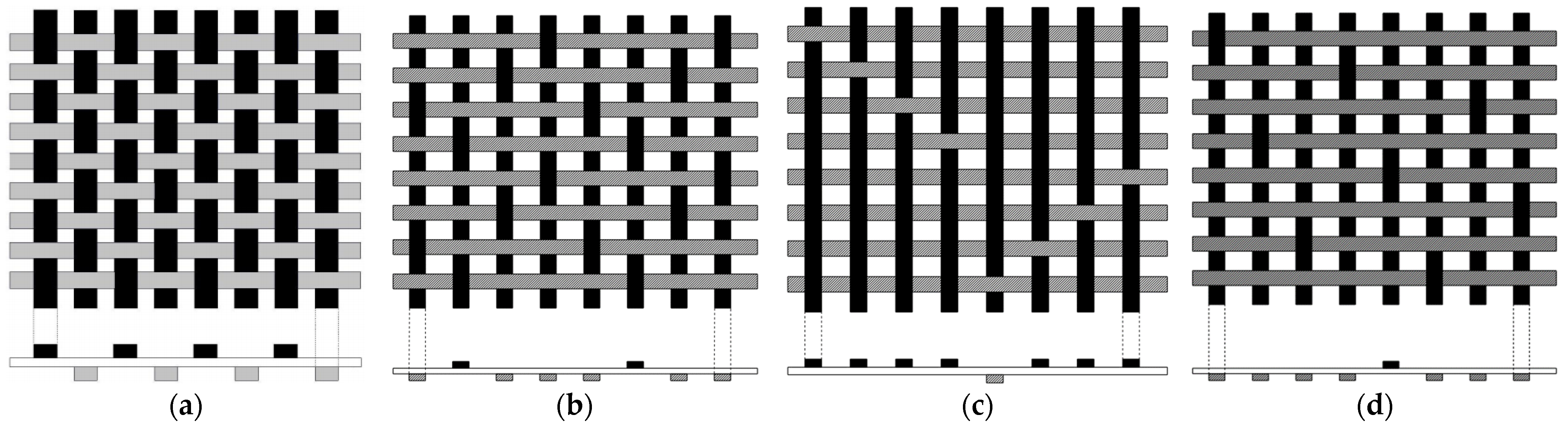
- Vishwanath, B.; Verma, A.P.; Rao, C.V.S.K. Effect of fabric geometry on friction and wear of glass-fibre-reinforced composites. Wear 1991, 145, 315–327. [Google Scholar] [CrossRef]
- Wang, S.; Bai, J.; Innocent, M.T.; Wang, Q.; Xiang, H.; Tang, J.; Zhu, M. Lignin-based carbon fibers: Formation, modification and potential applications. Green Energy Environ. 2021, 7, 578–605. [Google Scholar] [CrossRef]
- Qu, W.; Yang, J.; Sun, X.; Bai, X.; Jin, H.; Zhang, M. Towards producing high-quality lignin-based carbon fibers: A review of crucial factors affecting lignin properties and conversion techniques. Int. J. Biol. Macromol. 2021, 189, 768–784. [Google Scholar] [CrossRef]
- Banerjee, C.; Chandaliya, V.K.; Dash, P.S. Recent advancement in coal tar pitch-based carbon fiber precursor development and fiber manufacturing process. J. Anal. Appl. Pyrolysis 2021, 158, 105272. [Google Scholar] [CrossRef]
- Huang, J.; Ouyang, Q.; Li, M.; Heng, F.; Ma, H.; Chen, Y. Thermal behavior and thermal stabilization of guanidine hydro-chloride-modified acrylic fiber for preparation of low-cost carbon fiber. J. Therm. Anal. Calorim. 2018, 136, 2195–2203. [Google Scholar] [CrossRef]
- Chabaud, G.; Castro, M.; Denoual, C.; Le Duigou, A. Hygromechanical properties of 3D printed continuous carbon and glass fibre reinforced polyamide composite for outdoor structural applications. Addit. Manuf. 2019, 26, 94–105. [Google Scholar] [CrossRef]
- Forintos, N.; Czigány, T. Multifunctional application of carbon fiber reinforced polymer composites: Electrical properties of the reinforcing carbon fibers—A short review. Compos. Part B 2019, 162, 331–343. [Google Scholar] [CrossRef]
- Esawi, A.M.K.; Farag, M.M. Carbon nanotube reinforced composites: Potential and current challenges. Mater. Des. 2007, 28, 2394–2401. [Google Scholar] [CrossRef]
- Aamir, M.; Tolouei-Rad, M.; Giasin, K.; Nosrati, A. Recent advances in drilling of carbon fiber–reinforced polymers for aerospace applications: A review. Int. J. Adv. Manuf. Technol. 2019, 105, 2289–2308. [Google Scholar] [CrossRef]
- Karakassides, A.; Ganguly, A.; Tsirka, K.; Paipetis, A.S.; Papakonstantinou, P. Radially grown graphene nanoflakes on car-bon fibres as reinforcing interface for polymer composites. ACS Appl. Nano Mater. 2020, 3, 2402–2413. [Google Scholar] [CrossRef] [Green Version]
- Deborah, C. Carbon Fiber Composites; Elsevier: Amsterdam, The Netherlands, 2012. [Google Scholar]
- Zhang, Z.; Wilson, J.L.; Kitt, B.R.; Flaherty, D.W. Effects of oxygen plasma treatments on surface functional groups and shear strength of carbon fiber composites. ACS Appl. Nano Mater. 2021, 3, 986–995. [Google Scholar] [CrossRef]
- Shariatnia, S.; Kumar, A.V.; Kaynan, O.; Asadi, A. Hybrid Cellulose Nanocrystals-Bonded Carbon Nanotubes/Carbon Fiber Polymer Composites for Structural Applications. ACS Appl. Nano Mater. 2020, 3, 5421–5436. [Google Scholar] [CrossRef]
- Li, X.; Bai, M.Z.; Li, T.; Qiu, S.M.; Shi, H. Application of Carbon-Fiber Composite Material in Micropile Structure. J. Perform. Constr. Facil. 2020, 34, 04020017. [Google Scholar] [CrossRef]
- Luo, W.; Liu, Q.; Li, Y.; Zhou, S.; Zou, H.; Liang, M. Enhanced mechanical and tribological properties in polyphenylene sul-fide/polytetrafluoroethylene composites reinforced by short carbon fiber. Compos. Part B 2016, 91, 579–588. [Google Scholar] [CrossRef]
- Tenny, K.M.; Forner-Cuenca, A.; Chiang, Y.M.; Brushett, F.R. Comparing Physical and Electrochemical Properties of Different Weave Patterns for Carbon Cloth Electrodes in Redox Flow Batteries. J. Electrochem. Energy Convers. Storage 2020, 17, 041108-1–041108-13. [Google Scholar] [CrossRef]
- Mishra, S.P. A Text Book of Fibre Science and Technology; New Age International Private Ltd. Publishers: New Delhi, India, 2005; pp. 312–316. [Google Scholar]
- Chand, S. Review- Carbon fibers for composites. J. Mater. Sci. 2000, 35, 1303–1313. [Google Scholar] [CrossRef]
- Golewski, G.L. The Beneficial Effect of the Addition of Fly Ash on Reduction of the Size of Microcracks in the ITZ of Concrete Composites under Dynamic Loading. Energies 2021, 14, 668. [Google Scholar] [CrossRef]
- Golewski, G.L.; Gil, D.M. Studies of Fracture Toughness in Concretes Containing Fly Ash and Silica Fume in the First 28 Days of Curing. Materials 2021, 14, 319. [Google Scholar] [CrossRef] [PubMed]
- Abhilash, E.; Joseph, M.A. Carbon fibre reinforced aluminum matrix composite: Development & Evaluation of Mechanical Behaviors. In Proceedings of the Materials Science and Technology (MS&T) 2008, Pittsburgh, PA, USA, 5–9 October 2008. [Google Scholar]
- Rizkalla, S.; Dawood, M. High modulus carbon fiber materials for retrofit of steel structures and bridges. In Proceedings of the ACUN-5 International Composites Conference “Developments in Composites: Advanced, Infrastructural, Natural and Nano-Composites”, Sydney, Australia, 11–14 July 2006. [Google Scholar]
- Sayed, A.M. Fibrous polymeric composites. In Engineered Polymeric Fibrous Materials; Elsevier: Amsterdam, The Netherlands, 2021; pp. 1–58. [Google Scholar]
- Lionetto, F.; Moscatello, A.; Totaro, G.; Raffone, M.; Maffezzoli, A. Experimental and Numerical Study of Vacuum Resin Infusion of Stiffened Carbon Fiber Reinforced Panels. Materials 2020, 13, 4800. [Google Scholar] [CrossRef]
- Yue, L.; Bernd, Z.; Mike, S. Carbon Fiber Reinforced Polymer for CableStructures—A Review. Polymers 2015, 7, 2078–2099. [Google Scholar]
- Skarżyński, Ł. Mechanical and radiation shielding properties of concrete reinforced with boron-basalt fibers using Digital Image Correlation and X-ray micro-computed tomography. Constr. Build. Mater. 2020, 255, 119252. [Google Scholar] [CrossRef]
- Kumar, S.S.; Shankar, P.A.; Kumar, K.L. Failure investigation on high velocity impact deformation of Boron Carbide (B4C) reinforced fiber metal laminates of Titanium/Glass fiber reinforced polymer. Def. Technol. 2021, 18, 963–975. [Google Scholar] [CrossRef]
- Mehelli, O.; Derradji, M.; Belgacemi, R.; Abdous, S. Development of lightweight and highly efficient fast neutrons composites shields based on epoxy, UHMWPE fibres and boron carbide particles. Radiat. Phys. Chem. 2021, 193, 109510. [Google Scholar] [CrossRef]
- Buck, M.; Dorf, M. Boron Fibers in Composite Materials. Mater. Technol. 1995, 10, 13–16. [Google Scholar] [CrossRef]
- Hasan, Z. Composite materials. In Tooling for Composite Aerospace Structures; Butterworth-Heinemann: Oxford, UK, 2020; pp. 21–48. [Google Scholar] [CrossRef]
- Zweben, C.H. Composites: Overview. In Encyclopedia of Condensed Matter Physics; Academic Press: Cambridge, MA, USA, 2005; pp. 192–208. [Google Scholar] [CrossRef]
- Pakdel, E.; Kashi, S.; Varley, R.; Wang, X. Recent progress in recycling carbon fibre reinforced composites and dry carbon fibre wastes. Resour. Conserv. Recycl. 2020, 166, 105340. [Google Scholar] [CrossRef]
- Wawner, F.E. Boron and Silicon Carbide Fibers (CVD). In Comprehensive Composite Materials II; Elsevier: Amsterdam, The Netherlands, 2018; pp. 167–186. [Google Scholar]
- Meola, C.; Boccardi, S.; Carlomagno, G. Composite Materials in the Aeronautical Industry. In Infrared Thermography in the Evaluation of Aerospace Composite Materials; Woodhead Publishing: Thorston, UK, 2017; pp. 1–24. [Google Scholar]
- Vasiliev, V.V.; Morozov, E.V. Advanced Mechanics of Composite Materials and Structures; Elsevier: Amsterdam, The Netherlands, 2018. [Google Scholar]
- Chang, P.Y.; Yeh, P.C.; Yang, J.M. Fatigue crack initiation in hybrid boron/glass/aluminum fiber metal laminates. Mater. Sci. Eng. A 2008, 496, 273–280. [Google Scholar] [CrossRef]
- Burningham, N.W.; Rumpel, W.F. Properties of boron fibers and composites. Polym. Eng. Sci. 1967, 7, 124–127. [Google Scholar] [CrossRef]
- Maier, J.; Nöth, A. Wet-chemical coating of silicon carbide fibers with hexagonal boron nitride layers. J. Eur. Ceram. Soc. 2021, 41, 6207–6212. [Google Scholar] [CrossRef]
- Yamamoto, M.; Nishimura, Y.; Hayashida, M. Influence of Al particles as infiltration promoters on the interfacial reaction and mechanical property of a continuous SiC fiber/AZ91 composite fabricated by a low-pressure infiltration method. J. Alloys Compd. 2021, 887, 161461. [Google Scholar] [CrossRef]
- Yu, P.; Lin, Z.; Yu, J. Mechanical, thermal, and dielectric properties of SiCf/SiC composites reinforced with electrospun SiC fibers by PIP. J. Eur. Ceram. Soc. 2021, 41, 6859–6868. [Google Scholar] [CrossRef]
- Patil, N.; Zhao, X.; Mishra, N.; Saed, M.; Radovic, M.; Green, M.J. Rapid heating of silicon carbide fibers under Radio Frequency fields and application in curing preceramic polymer composites. ACS Appl. Mater. Interfaces 2019, 11, 46132–46139. [Google Scholar] [CrossRef]
- Szostak, B.; Golewski, G.L. Improvement of Strength Parameters of Cement Matrix with the Addition of Siliceous Fly Ash by Using Nanometric C-S-H Seeds. Energies 2020, 13, 6734. [Google Scholar] [CrossRef]
- Köken, D.; Top, A.; Çakmak Cebeci, F.; Turgut, F.; Bozali, B.; Özden-Yenigün, E.; Cebeci, H. An effective growth of hierarchical BNNTs/SiC fibers with enhanced interfacial properties. Compos. Sci. Technol. 2021, 216, 109033. [Google Scholar] [CrossRef]
- Chen, X.; Sun, Z.; Niu, X.; Bian, J.; Song, Y.; Liu, J. Evolution of the structure and mechanical performance of Cansas-II SiC fibres after thermal treatment. Ceram. Int. 2021, 47, 27217–27229. [Google Scholar] [CrossRef]
- Chen, X.; Sun, Z.; Han, X.; Niu, X.; Song, Y. Evolution of microstructure and tensile strength of Cansas-II SiC fibers under air oxidizing atmosphere. J. Eur. Ceram. Soc. 2021, 41, 7585–7600. [Google Scholar] [CrossRef]
- An, Q.; Chen, J.; Ming, W.; Chen, M. Machining of SiC ceramic matrix composites: A review. Chin. J. Aeronaut. 2020, 34, 540–567. [Google Scholar] [CrossRef]
- Wang, L.-Y.; Luo, R.-Y.; Cui, G.; Chen, Z. Oxidation resistance of SiCf/SiC composites with a PyC/SiC multilayer interface at 500 °C to 1100 °C. Corros. Sci. 2020, 167, 108522. [Google Scholar] [CrossRef]
- Ahn, S.B.; Nguyen, M.D.; Bang, J.W.; Kim, Y.; Lee, Y.; Shin, D.G.; Kwon, W.T. SiC-conversion coating from silica sol for improved oxidation resistance of carbon-fiber insulator in solar-cell ingot-growing crucibles. Thin Solid Film. 2019, 694, 137748. [Google Scholar] [CrossRef]
- Golewski, G.L. new principles for implementation and operation of foundations for machines: A review of recent advances. Struct. Eng. Mech. 2019, 71, 317–327. [Google Scholar]
- Polozov, I.; Razumov, N.; Masaylo, D.; Silin, A.; Lebedeva, Y.; Popovich, A. Fabrication of Silicon Carbide Fiber-Reinforced Silicon Carbide Matrix Composites Using Binder Jetting Additive Manufacturing from Irregularly-Shaped and Spherical Powders. Materials 2020, 13, 1766. [Google Scholar] [CrossRef] [Green Version]
- Ji, R.; Liu, Y.; Zhang, Y.; Cai, B.; Li, X.; Zheng, C. Effect of machining parameters on surface integrity of silicon carbide ceramic using end electric discharge milling and mechanical grinding hybrid machining. J. Mech. Sci. Technol. 2013, 27, 177–183. [Google Scholar] [CrossRef]
- Brunner, A. Experimental aspects of Mode I and Mode II fracture toughness testing of fibre-reinforced polymer-matrix composites. Comput. Methods Appl. Mech. Eng. 2000, 185, 161–172. [Google Scholar] [CrossRef]
- Marsavina, L.; Constantinescu, D.M.; Linul, E.; Stuparu, F.A.; Apostol, D.A. Experimental and numerical crack paths in PUR foams. Eng. Fract. Mech. 2016, 167, 68–83. [Google Scholar] [CrossRef]
- Marsavina, L.; Constantinescu, D.M.; Linul, E.; Voiconi, T.; Apostol, D.A.; Sadowski, T. Evaluation of mixed mode fracture for PUR foams. Procedia Mater. Sci. 2014, 3, 1342–1352. [Google Scholar] [CrossRef] [Green Version]
- Linul, E.; Marsavina, L.; Sadowski, T.; Kneć, M. Size effect on fracture toughness of rigid polyurethane foams. Solid State Phenom. 2012, 188, 205–210. [Google Scholar] [CrossRef]
- Golewski, G.L. generalized fracture toughness and compressive strength of sustainable concrete including low calcium fly ash. Materials 2017, 10, 1393. [Google Scholar] [CrossRef] [PubMed] [Green Version]
- Linul, E.; Serban, D.A.; Marsavina, L. Influence of cell topology on mode I fracture toughness of cellular structures. Phys. Mesomech. 2018, 21, 178–186. [Google Scholar] [CrossRef]
- Linul, E.; Marşavina, L.; Stoia, D.I. Mode I and II fracture toughness investigation of Laser-Sintered Polyamide. Theor. Appl. Fract. Mech. 2020, 106, 102497. [Google Scholar] [CrossRef]
- Arumugam, V.; Sajith, S.; Stanley, A.J. Acoustic Emission Characterization of Failure Modes in GFRP Laminates Under Mode I Delamination. J. Nondestruct. Eval. 2011, 30, 213–219. [Google Scholar] [CrossRef]
- Manshadi, B.D.; Vassilopoulos, A.P.; Botsis, J. A combined experimental/numerical study of the scaling effects on mode I delamination of GFRP. Compos. Sci. Technol. 2013, 83, 32–39. [Google Scholar] [CrossRef]
- Birsan, M.; Sadowski, T.; Marsavina, L.; Linul, E.; Pietras, D. Mechanical behavior of sandwich composite beams made of foams and functionally graded materials. Int. J. Solids Struct. 2013, 50, 519–530. [Google Scholar] [CrossRef] [Green Version]
- Linul, E.; Marsavina, L. Assesment of sandwich beams with rigid polyurethane foam core using failure-mode maps. Proc. Rom. Acad.-Ser. A 2015, 16, 522–530. [Google Scholar]
- Remmers, J.J.; Borst, R. Delamination buckling of fibre–metal laminates. Compos. Sci. Technol. 2001, 61, 2207–2213. [Google Scholar] [CrossRef] [Green Version]
- Parlapalli, M.R.; Soh, K.C.; Shu, D.W.; Ma, G. Experimental investigation of delamination buckling of stitched composite laminates. Compos. Part A 2007, 38, 2024–2033. [Google Scholar] [CrossRef]
- Panigrahi, S.K.; Pradhan, B. Through-the-width delamination damage propagation characteristics in single-lap laminated FRP composite joints. Int. J. Adhes. Adhes. 2009, 29, 114–124. [Google Scholar] [CrossRef]
- Benzeggagh, M.L.; Kenane, M. Measurement of mixed-mode delamination fracture toughness of unidirectional glass/epoxy composites with mixed-mode bending apparatus. Compos. Sci. Technol. 1996, 56, 439–449. [Google Scholar] [CrossRef]
- Berthelot, J.M. Transverse cracking and delamination in cross-ply glass-fiber and carbon-fiber reinforced plastic laminates: Static and fatigue loading. Appl. Mech. Rev. 2003, 56, 111–147. [Google Scholar] [CrossRef]
- Kim, J.K.; Baillie, C.; Mai, Y.W. Interfacial debonding and fibre pull-out stresses. J. Mater. Sci. 1992, 27, 3143–3154. [Google Scholar] [CrossRef]
- Stang, H.; Shah, S.P. Failure of fibre-reinforced composites by pull-out fracture. J. Mater. Sci. 1986, 21, 953–957. [Google Scholar] [CrossRef]
- Cantwell, W.J.; Morton, J. The impact resistance of composite materials—A review. Composites 1991, 22, 347–362. [Google Scholar] [CrossRef]
- Nairn, J.A.; Hu, S.; Bark, J.S. A critical evaluation of theories for predicting microcracking in composite laminates. J. Mater. Sci. 1993, 28, 5099–5111. [Google Scholar] [CrossRef]
- Krishnan, P. Department of Manufacturing Engineering, School of Mechanical Engineering, VIT University, Vellore, India. In Mechanical and Physical Testing of Biocomposites, Fibre-Reinforced Composites and Hybrid Composites; Elsevier: Amsterdam, The Netherlands, 2018; p. 343. [Google Scholar]


| Material | Matrix | Fiber Weight Fraction | Laminate Specific Gravity | Tensile Strength (MPa) | Tensile Modulus (MPa) | Specific Tensile Modulus (MPa) | Specific Tensile Strength (MPa) | Compressive Strength (MPa) | Compressive Modulus (MPa) |
|---|---|---|---|---|---|---|---|---|---|
| AR K49, Woven | Polyester | 0.44 | 1.31 | 430 | 25,994 | 19,857 | 329 | 115 | 16,272 |
| AR K49, Woven | Epoxy | 0.55 | 1.31 | 450 | 29,993 | 22,890 | 344 | 172 | - |
| Kevlar 49 (1350) | Polyester | 0.42 | 1.293 | 372 | 19,306 | - | - | 115 | 17,927 |
| Kevlar 49 (1350S) | Polyester | 0.42 | 1.3 | 384 | 23,925 | - | - | 114 | 19,306 |
| AR 900S | Polyester | 0.48 | 1.294 | 443 | 26,614 | - | - | 103 | 19,306 |
| Fiber Product | Base Polymer | Fiber Producer | Application |
|---|---|---|---|
| p-AR fibers | |||
| Kevlar | Poly(p-phenylene terephthalamide) | DuPont Co. | Goods offered to give multi-threat security |
| Twaron | Poly(p-phenylene terephthalamide) | Akzo Nobel | PVB Prepreg |
| SVM | Poly[5-amino-2-(p-aminophenyl) benzimidazole terephthalamide] | Russia | Bulletproof vest and helmets |
| m-AR fibers | |||
| Nomex | Poly(m-phenylene isophthalamide) | DuPont Co. | Flame barrier for aircraft insulation |
| Teijinconex | Poly(m-phenylene isophthalamide) | Teijin Ltd. | Hoses, filters, and copy cleaners. |
| Fenilin | Poly(m-phenylene isophthalamide) | Russia | Fire resistance application |
| AR copolymer fibers | |||
| Technora | Copoly(1,4-phenylene/3,4’-diphenylether terephthalamide) | Teijin Ltd. | Radiation shielding |
| Armos | Copoly[p-phenylene/5-amino- 2—(p-aminophenyl)benzimidazole terephthalamide] | Russia | Open fire resistance |
| Trevar | Aramid copolymer | Hoechst AG | Aerospace and military |
| Properties | HDPE | LDPE | LLDPE |
|---|---|---|---|
| Melting point (°C) | 120 to 140 | 105 to 115 | 115 to 135 |
| Density (g/cm3) | 0.941 to 0.965 | 0.910 to 0.925 | 0.91 to 0.94 |
| Continuous temperature (°C) | −50 to +60 | 80 to 95 | 90 to 110 |
| Crystallinity | High-crystalline | Low-crystalline | Semi-crystalline |
| Electrical insulation | Excellent | Excellent | Excellent |
| Water absorption | Very low | Very low | Low |
| Recycling Code |  |  |  |
| Characteristics | Higher tensile strength | High impact strength | Higher tensile and impact strength |
| Application | Low-molded bottles for milk, grocery bags, construction film, agricultural mulch, injection-molded pails, caps, appliance housings, and toys | Packaging film, garbage and grocery bags, agricultural mulch, wire, and cable insulation, squeeze bottles, toys, and housewares | Liquid containers, paperboard packaging, stronger films, etc. |
| Properties | Phthalic Anhydride | Isophthalic Acid | Terephthalic Acid | 2,6-Naphthalene Dicarboxylic Acid |
|---|---|---|---|---|
| Melting point (°C) | 131 | 341–343 | 427 | >300 |
| Density (g/cm3) | 1.53 | 1.53 | 1.522 | 1.5 |
| Boiling point (°C) | 295 | 412.3 | Decomposes | 437.3 |
| Molecular weight (g/mol) | 148.1 | 166.14 | 166.13 | 216.192 |
| Chemical formula | C8H4O3 | C8H6O4 | C8H6O4 | C12H8O4 |
| Solubility in water | Respond slowly | Insoluble | Soluble | Soluble |
| Properties | Aluminum-Filled Nylon | Glass-Filled Nylon | Carbon Fiber-Filled Nylon |
|---|---|---|---|
| Tensile Strength (MPa) | 48 ± 3 | 51 ± 3 | 76 ± 34 |
| Density (g/cm3) | 1.36 ± 0.05 | 1.22 ± 0.03 | 1.9 ± 1.2 |
| Heat Deflection Temperature(°C) | 130 | 110 | 143 |
| Ball Indentation Hardness | - | 98 | 270 |
| Flexural Modulus(MPa) | 3600 ± 150 | 2900 ± 150 | 10,300 ± 2070 |
| Elongation at Break(%) | 3.5 ± 1 | 6 ± 3 | |
| Tensile Modulus(MPa) | 3800 ± 150 | 3200 ± 200 | 7600 ± 2300 |
| GFs Type | Oxide | |||||||||||
|---|---|---|---|---|---|---|---|---|---|---|---|---|
| SiO2 | Al2O3 | TiO2 | B2O3 | CaO | MgO | BaO | LiO2 | Fe2O3 | F2 | ZrO2 | Na2O + K2O | |
| A-glass | 63–72 | 3.5 | 0–6 | 1.5 | 6.5 | 4.5 | --- | --- | 0–6 | 0–6 | --- | 14–16 |
| E-glass | 54–62 | 14 | 0.2 | 7.0 | 22 | 1.0 | --- | --- | 0–2 | 0–1 | --- | 0–2 |
| C-glass | 65 | 4.1 | --- | 5.0 | 13.4 | 3.3 | 0–1 | --- | 0–0.8 | --- | --- | 7–10 |
| AR-glass | 55–75 | 0–5 | 0–12 | 0–8 | 1–10 | --- | --- | 1–18 | 0–0.8 | 0–5 | 1–18 | 0–5 |
| S-2-glass | 65–66 | 24–25 | --- | --- | 0–0.1 | 9.5–10 | --- | --- | 0–0.1 | --- | --- | 0–0.2 |
| D-glass | 74 | --- | --- | 22.5 | 0–1 | --- | --- | --- | 0–0.3 | --- | --- | 0–4 |
| R-glass | 60 | 24 | --- | --- | 9–25 | 3–8 | --- | --- | --- | 0–0.3 | --- | 0–1 |
| Type of Fiber | Precursor Material | Density (kg/m3) | Tensile Strength [GPa] | Tenacity (GPa) | Young’s Modulus (GPa) | Maximum Elongation (%) |
|---|---|---|---|---|---|---|
| HTS | PAN | 1760 | 3–5 | 2.8–4 | 200–250 | 1.2–1.4 |
| UHTS | PAN | 1820 | --- | 4.1–5.7 | 260–290 | 0.8–1.0 |
| LM | Pitch | 1500 | 2–4 | 0.6–1.0 | 200–250 | 2.0–5.0 |
| IM | Pitch | 1780 | 4–7 | --- | 250–350 | 1–2 |
| HM | PAN/Mesophase pitch | 1820 | 2–4.5 | 1.7–3.5 | 350–450 | 0.6–0.7 |
| UHM | Mesophase pitch | 2100 | 3 | 2.1–2.4 | 520–550 | 0.3–0.4 |
| Properties | Unit | Value |
|---|---|---|
| Tensile strength | (GPa) | 3–4 |
| Density | (g/cm3) | 2.48–2.83 |
| Young’s modulus | (GPa) | 380–400 |
| Melting temperature | (°C) | 2040 |
| Coefficient of thermal expansion | (°C−1) | 8.3 × 10⁻⁶ |
| Elastic modulus | (GPa) | 379.21 |
| Tensile elongation | (%) | 0.9 |
| Compression Strength | (GPa) | >6 |
| Hardness | (Knoop) | 3200 |
| Properties | Unit | Value |
|---|---|---|
| Density | (g/cm3) | 3.02 |
| Bending strength | (MPa) | 250 (20 °C) |
| (MPa) | 280 (1200 °C) | |
| Elastic modulus | (GPa) | 330 (20 °C) |
| (GPa) | 300 (1200 °C) | |
| Thermal conductivity | (W/mk) | 45 (1200 °C) |
| Specific heat | (J/Kg °K) | 750 |
| Thermal expansion coefficient | (K−1 × 10⁶) | 4.5 |
| Mohs hardness | (−) | 13 |
| Acid and alkali resistance | (−) | Excellent |
| Flexural strength | (MPa) | 550 |
| Compressive strength | (MPa) | 3900 |
| Volume resistivity | (Ohm cm) | 102–106 |
| Maximum service temperature | (°C) | 1650 |
Publisher’s Note: MDPI stays neutral with regard to jurisdictional claims in published maps and institutional affiliations. |
© 2022 by the authors. Licensee MDPI, Basel, Switzerland. This article is an open access article distributed under the terms and conditions of the Creative Commons Attribution (CC BY) license (https://creativecommons.org/licenses/by/4.0/).
Share and Cite
Rajak, D.K.; Wagh, P.H.; Linul, E. A Review on Synthetic Fibers for Polymer Matrix Composites: Performance, Failure Modes and Applications. Materials 2022, 15, 4790. https://doi.org/10.3390/ma15144790
Rajak DK, Wagh PH, Linul E. A Review on Synthetic Fibers for Polymer Matrix Composites: Performance, Failure Modes and Applications. Materials. 2022; 15(14):4790. https://doi.org/10.3390/ma15144790
Chicago/Turabian StyleRajak, Dipen Kumar, Pratiksha H. Wagh, and Emanoil Linul. 2022. "A Review on Synthetic Fibers for Polymer Matrix Composites: Performance, Failure Modes and Applications" Materials 15, no. 14: 4790. https://doi.org/10.3390/ma15144790