
Hierarchical and Heterogeneous Porosity Construction and Nitrogen Doping Enabling Flexible Carbon Nanofiber Anodes with High Performance for Lithium-Ion Batteries

 , and
, and
Abstract
:1. Introduction
2. Experimental
2.1. Materials
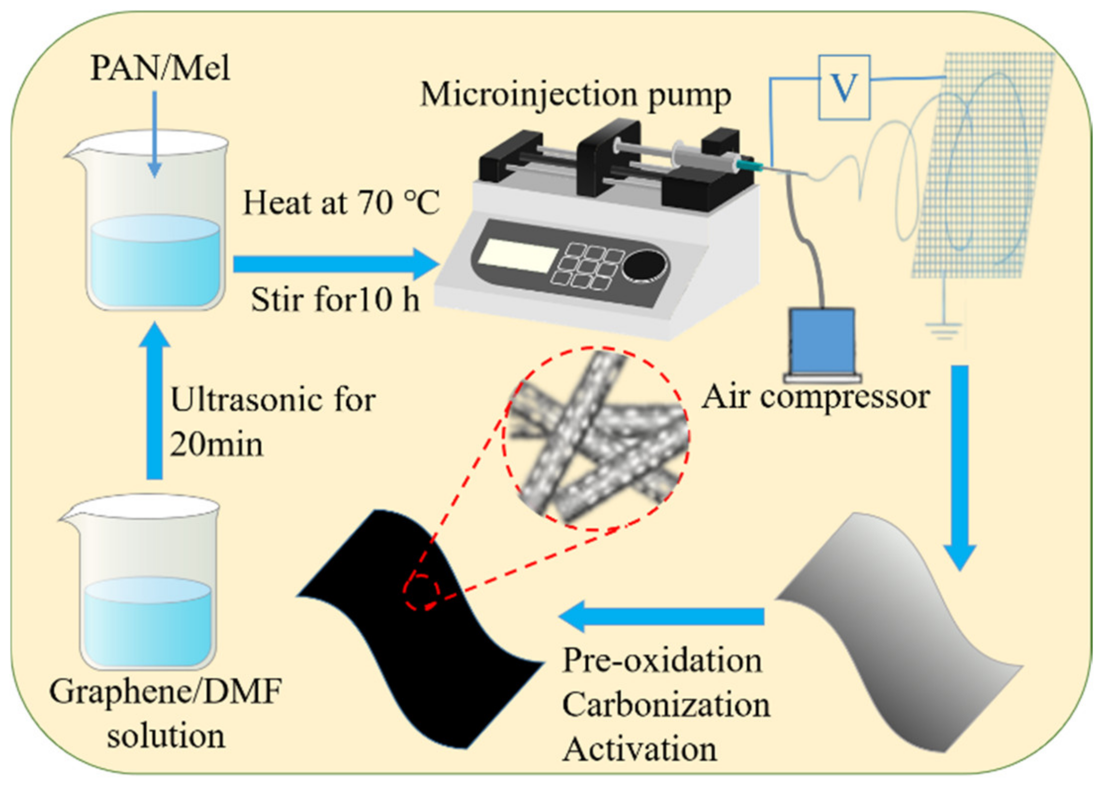
2.2. Preparation of NH3-Activated Carbon Nanofibers
2.3. Preparation of N-Doped Carbon Nanofibers
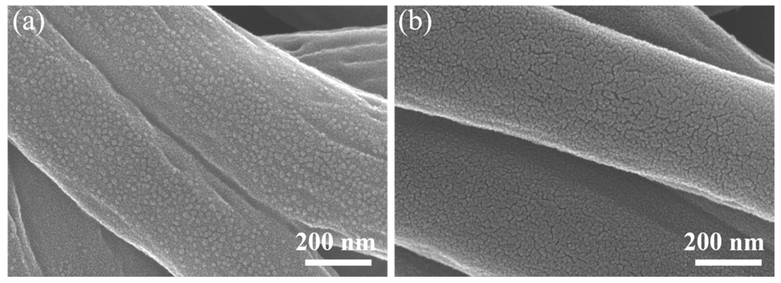
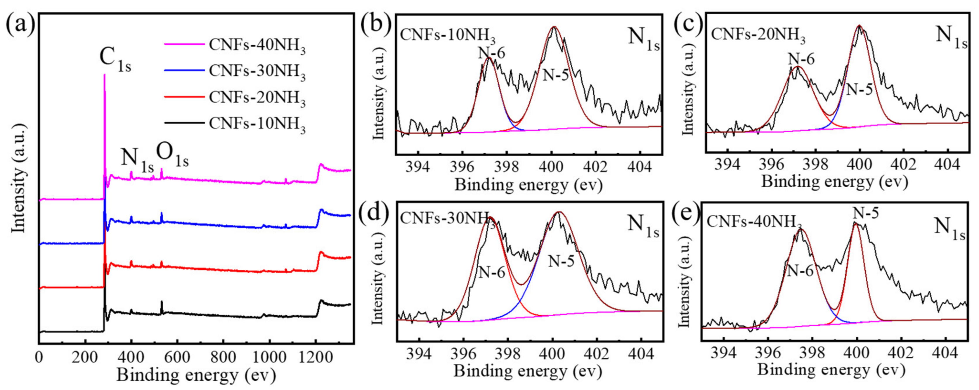
2.4. Materials Characterization
2.5. Electrochemical Measurements
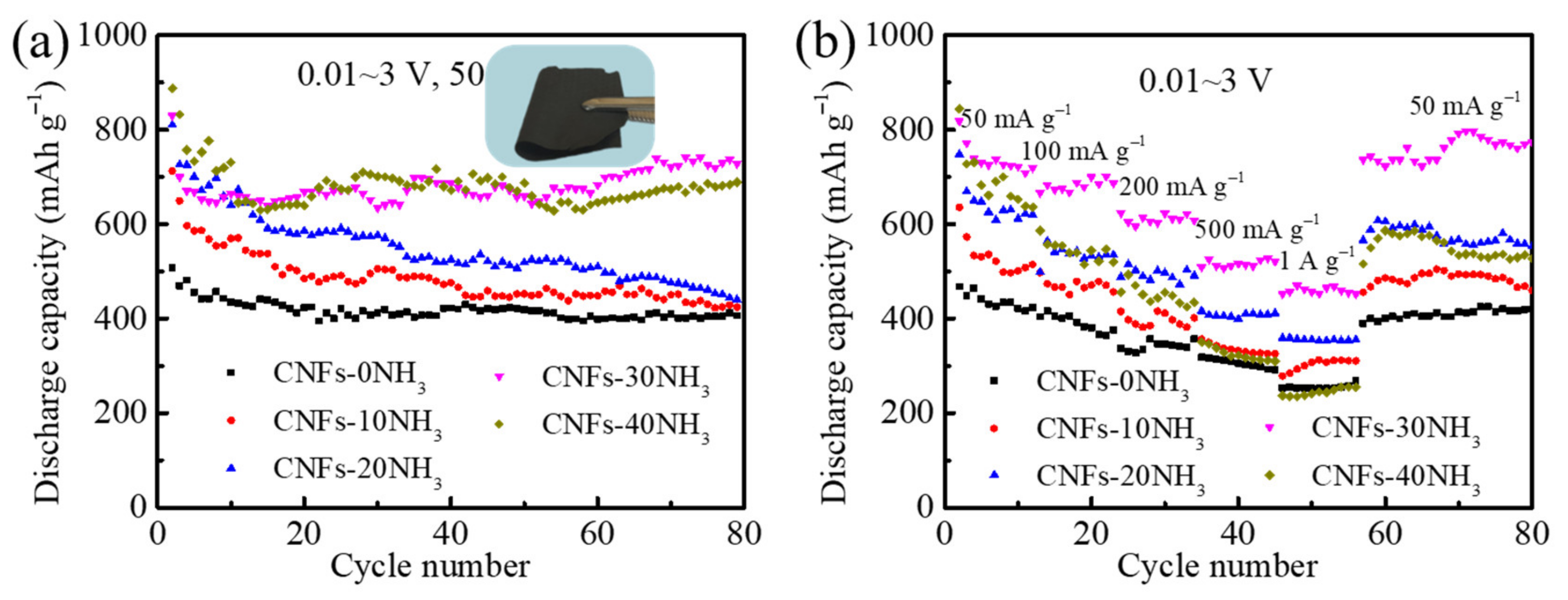
3. Results and Discussion
4. Conclusions
Author Contributions
Funding
Institutional Review Board Statement
Informed Consent Statement
Data Availability Statement
Conflicts of Interest
References
- Alain, M.; Christian, M.J.; John, B.G.; Karim, Z. Tribute to michel armand: From rocking chair–Li-ion to solid-state lithium batteries. J. Electrochem. Soc. 2020, 167, 070507. [Google Scholar]
- Alvaro, M.; James, M.; William, A.P. Opportunities and challenges of lithium ion batteries in automotive applications. ACS Energy Lett. 2021, 6, 621–630. [Google Scholar]
- Wang, P.; Hu, M.; Wang, H.; Chen, Z.; Feng, Y.; Wang, J.; Ling, W.; Huang, Y. The evolution of flexible electronics: From nature, beyond nature, and to nature. Adv. Sci. 2020, 7, 2001116. [Google Scholar] [CrossRef] [PubMed]
- Fu, J.; Kang, W.B.; Guo, X.D.; Wen, H.; Zeng, T.B.; Yuan, R.X.; Zhang, C.H. 3D hierarchically porous NiO/graphene hybrid paper anode for long-life and high rate cycling flexible Li-ion batteries. J. Energy Chem. 2020, 47, 172–179. [Google Scholar] [CrossRef]
- Zeng, L.C.; Qiu, L.; Cheng, H.M. Towards the practical use of flexible lithium ion batteries. Energy Storage Mater. 2019, 23, 434–438. [Google Scholar] [CrossRef]
- Joshi, B.; Samuel, E.; Kim, Y.I.; Yarin, A.L.; Swihart, M.T.; Yoon, S.S. Progress and potential of electrospinning-derived substrate-free and binder-free lithium-ion battery electrodes. Chem. Eng. J. 2022, 430, 132876. [Google Scholar] [CrossRef]
- Zhang, T.; Zhang, L.; Zhao, L.N.; Huang, X.X.; Li, W.; Li, T.; Shen, T.; Sun, S.N.; Hou, Y.L. Free-standing, foldable V2O3/multichannel carbon nanofibers electrode for flexible Li-Ion batteries with ultralong lifespan. Small 2020, 16, 2005302. [Google Scholar] [CrossRef]
- Li, W.H.; Li, M.S.; Wang, M.; Zeng, L.C.; Yu, Y. Electrospinning with partially carbonization in air: Highly porous carbon nanofibers optimized for high-performance flexible lithium-ion batteries. Nano Energy 2015, 13, 693–701. [Google Scholar] [CrossRef]
- Zhu, S.Q.; Huang, A.M.; Wang, Q.; Xu, Y. MOF-derived porous carbon nanofibers wrapping Sn nanoparticles as flexible anodes for lithium/sodium ion batteries. Nanotechnology 2021, 32, 165401. [Google Scholar] [CrossRef]
- Nan, D.; Huang, Z.H.; Lv, R.T.; Yang, L.; Wang, J.G.; Shen, W.C.; Liu, Y.X.; Yu, X.L.; Ye, L.; Sun, H.Y.; et al. Nitrogen-enriched electrospun porous carbon nanofiber networks as high-performance free-standing electrode materials. J. Mater. Chem. A 2014, 2, 19678–19684. [Google Scholar] [CrossRef]
- Mao, Y.; Duan, H.; Xu, B.; Zhang, L.; Hu, Y.S.; Zhao, C.C.; Wang, Z.X.; Chen, L.Q.; Yang, Y.S. Lithium storage in nitrogen-rich mesoporous carbon materials. Energy Environ. Sci. 2012, 5, 7950–7955. [Google Scholar] [CrossRef]
- Tan, Z.Q.; Ni, K.; Chen, G.X.; Zeng, W.C.; Tao, Z.C.; Ikram, M.; Zhang, Q.B.; Wang, H.J.; Sun, L.T.; Zhu, X.J.; et al. Incorporating pyrrolic and pyridinic nitrogen into a porous carbon made from C60 molecules to obtain superior energy storage. Adv. Mater. 2017, 29, 1603414. [Google Scholar] [CrossRef]
- Liu, C.; Xiao, N.; Wang, Y.W.; Zhou, Y.; Wang, G.; Li, H.Q.; Ji, Y.Q.; Qiu, J.S. Electrospun nitrogen-doped carbon nanofibers with tuned microstructure and enhanced lithium storage properties. Carbon 2018, 139, 716–724. [Google Scholar] [CrossRef]
- Xia, J.; Liu, L.; Jamil, S.; Xie, J.J.; Yan, H.X.; Yuan, Y.T.; Zhang, Y.; Nie, S.; Pan, J.; Wang, X.Y.; et al. Free-standing SnS/C nanofiber anodes for ultralong cycle-life lithium-ion batteries and sodium-ion batteries. Energy Storage Mater. 2019, 17, 1–11. [Google Scholar] [CrossRef]
- Chen, Y.J.; Zhao, X.H.; Liu, Y.; Razzaq, A.A.; Haridas, A.K.; Cho, K.K.; Peng, Y.; Deng, Z.; Ahn, J.H. γ-Fe2O3 nanoparticles aligned in porous carbon nanofibers towards long life-span lithium ion batteries. Electrochim. Acta 2018, 289, 264–271. [Google Scholar] [CrossRef]
- Zhao, Q.S.; Liu, J.L.; Li, X.X.; Xia, Z.Z.; Zhang, Q.X.; Zhou, M.; Tian, W.; Wang, M.; Hu, H.; Li, Z.T.; et al. Graphene oxide-induced synthesis of button-shaped amorphous Fe2O3/rGO/CNFs films as flexible anode for high-performance lithium-ion batteries. Chem. Eng. J. 2019, 369, 215–222. [Google Scholar] [CrossRef]
- Zhao, H.; Yin, H.; Yu, X.X.; Zhang, W.; Li, C.; Zhu, M.Q. In2O3 nanoparticles/carbonfiber hybrid mat as free-standing anode for lithium-ion batteries with enhanced electrochemical performance. J. Alloy. Compd. 2018, 735, 319–326. [Google Scholar] [CrossRef]
- Han, Z.S.; Kong, F.J.; Zheng, J.H.; Chen, J.Y.; Tao, S.; Qian, B. MnSe nanoparticles encapsulated into N-doped carbon fibers with a binder-free and free-standing structure for lithium ion batteries. Ceram. Int. 2021, 47, 1429–1438. [Google Scholar] [CrossRef]
- Guo, J.Y.; Liu, J.Q.; Dai, H.H.; Zhou, R.; Wang, T.Y.; Zhang, C.C.; Ding, S.; Wang, H.G. Nitrogen doped carbon nanofiber derived from polypyrrole functionalized polyacrylonitrile for applications in lithium-ion batteries and oxygen reduction reaction. J. Colloid Interf. Sci. 2017, 507, 154–161. [Google Scholar] [CrossRef]
- Abe, J.; Takahashi, K.; Kawase, K.; Kobayashi, Y.; Shiratori, S. Self-standing carbon nanofiber and SnO2 nanorod composite as a high-capacity and high-rate-capability anode for lithium-ion batteries. Acs Appl. Nano Mater. 2018, 1, 2982–2989. [Google Scholar] [CrossRef]
- Ma, X.X.; Hou, G.M.; Ai, Q.; Zhang, L.; Si, P.C.; Feng, J.K.; Ci, L.J. A heart-coronary arteries structure of carbon nanofibers/graphene/silicon composite anode for high performance lithium ion batteries. Sci. Rep. 2017, 7, 9642. [Google Scholar] [CrossRef]
- Wu, S.H.; Han, Y.D.; Wen, K.C.; Wei, Z.H.; Chen, D.J.; Lv, W.Q.; Lei, T.Y.; Xiong, J.; Gu, M.; He, W.D. Composite nanofibers through in-situ reduction with abundant active sites as flexible and stable anode for lithium ion batteries. Compos. Part B-Eng. 2019, 161, 369–375. [Google Scholar] [CrossRef]
- Li, X.Q.; Xiang, J.; Zhang, X.K.; Li, H.B.; Yang, J.N.; Zhang, Y.M.; Zhang, K.Y.; Chu, Y.Q. Electrospun FeCo nanoparticles encapsulated in N-doped carbon nanofibers as self-supporting flexible anodes for lithium-ion batteries. J. Alloy. Compd. 2021, 873, 159703. [Google Scholar] [CrossRef]
- Mou, H.Y.; Chen, S.X.; Xiao, W.; Miao, C.; Li, R.; Xu, G.L.; Xin, Y.; Nie, S.Q. Encapsulating homogenous ultra-fine SnO2/TiO2 particles into carbon nanofibers through electrospinning as high-performance anodes for lithium-ion batteries. Ceram. Int. 2021, 47, 19945–19954. [Google Scholar] [CrossRef]
- Zhang, X.Y.; Gao, M.Z.; Wang, W.; Liu, B.; Li, X.B. Encapsulating MoO2 nanocrystals into flexible carbon nanofibers via electrospinning for high-performance lithium storage. Polymers 2021, 13, 22. [Google Scholar] [CrossRef]
- Chen, R.Z.; Hu, Y.; Shen, Z.; Pan, P.; He, X.; Wu, K.S.; Zhang, X.W.; Cheng, Z.L. Facile fabrication of foldable electrospun polyacrylonitrile-based carbon nanofibers for flexible lithium-ion batteries. J. Mater. Chem. A 2017, 5, 12914–12921. [Google Scholar] [CrossRef]
- Guo, L.G.; Sun, H.; Qin, C.Q.; Li, W.; Wang, F.; Song, W.L.; Du, J.; Zhong, F.; Ding, Y. Flexible Fe3O4 nanoparticles/N-doped carbon nanofibers hybrid film as binder-free anode materials for lithium-ion batteries. Appl. Surf. Sci. 2018, 459, 263–270. [Google Scholar] [CrossRef]
- Joshi, B.N.; An, S.; Yong, Y.I.; Samuel, E.P.; Song, K.Y.; Seong, I.W.; Al-Deyab, S.S.; Swihart, M.T.; Yoon, W.Y.; Yoon, S.S. Flexible freestanding Fe2O3-SnOx-carbon nanofiber composites for Liion battery anodes. J. Alloy. Compd. 2017, 700, 259–266. [Google Scholar] [CrossRef]
- Gao, S.; Zhang, D.; Zhu, K.; Tang, J.A.; Gao, Z.M.; Wei, Y.J.; Chen, G.; Gao, Y. Flexible V2O3/carbon nano-felts as free-standing electrode for high performance lithium ion batteries. J. Alloy. Compd. 2017, 702, 13–19. [Google Scholar] [CrossRef]
- Zhang, T.; Qiu, D.P.; Hou, Y.L. Free-standing and consecutive ZnSe@carbon nanofibers architectures as ultra-long lifespan anode for flexible lithium-ion batteries. Nano Energy 2022, 94, 106909. [Google Scholar] [CrossRef]
- Ma, M.B.; Wang, H.J.; Li, X.; Peng, K.; Xiong, L.L.; Du, X.F. Free-standing SiOC/nitrogen-doped carbon fibers with highly capacitive Li storage. J. Eur. Ceram. Soc. 2020, 40, 5238–5246. [Google Scholar] [CrossRef]
- Zhang, S.G.; Yue, L.C.; Wang, M.; Feng, Y.; Li, Z.; Mi, J. SnO2 nanoparticles confined by N-doped and CNTs-modified carbon fibers as superior anode material for sodium-ion battery. Solid State Ion. 2018, 323, 105–111. [Google Scholar] [CrossRef]
- Su, Y.; Fu, B.; Yuan, G.L.; Ma, M.; Jin, H.Y.; Xie, S.H.; Li, J.Y. Three-dimensional mesoporous γ-Fe2O3@carbon nanofiber network as high performance anode material for lithium- and sodium-ion batteries. Nanotechnology 2020, 31, 155401. [Google Scholar] [CrossRef] [PubMed]
- Liu, X.L.; Meng, Y.S.; Li, R.N.; Du, M.Q.; Zhu, F.L.; Zhang, Y. Nitrogen-doped carbon-coated cotton-derived carbon fibers as high-performance anode materials for lithium-ion batteries. Ionics 2019, 25, 5799–5807. [Google Scholar] [CrossRef]
- Chan, C.K.; Peng, H.L.; Liu, G.; Mcllwrath, K.; Zhang, X.F.; Huggins, R.A.; Cui, Y. High-performance lithium battery anodes using silicon nanowires. Nat. Nanotechnol. 2008, 3, 31–35. [Google Scholar] [CrossRef]


| Anodes | Mass Loading (mg cm−2) | First Reversible Capacity (mAh g−1) | Cycle Performance (mAh g−1) | Rate Performance (mAh g−1) | Reference |
|---|---|---|---|---|---|
| V2O3/MCCNFs | 1.5~2.5 | 790.6 (0.1 A g−1) | 487.7 (5 A g−1, 5000 cycles) | 456.8 (5 A g−1) | [7] |
| Sn@C@CNF | 2.0 | 891.2 (0.1 A g−1) | 610.8 (0.2 A g−1, 180 cycles) | 305.1 (2 A g−1) | [9] |
| SnS/CNFs | / | 898 (0.05 A g−1) | 548 (0.5 A g−1, 500 cycles) | 206 (4 A g−1) | [14] |
| γ-Fe2O3/C films | 1.0 | 923.97 (0.2 A g−1) | 1088 (0.2 A g−1, 300 cycles) | 380 (5 A g−1) | [15] |
| am-Fe2O3/rGO/CNFs | 1.5~2.0 | 825 (0.1 A g−1) | 739 (1 A g−1, 400 cycles) | 570 (2 A g−1) | [16] |
| In2O3@CF | 1.4 | 510 (0.1 A g−1) | 435 (0.1 A g−1, 500 cycles) | 190 (1.5 A g−1) | [17] |
| MnSe@C-700 | 1.6 | 614.6 (0.1 A g−1) | 684 (0.1 A g−1, 100 cycles) | / | [18] |
| NCNFs | 7.64 | 752.3 (0.05 A g−1) | 411.9 (0.1 A g−1, 160 cycles) | 148.8 (2 A g−1) | [19] |
| CNF@SnO2 | 1.77~3.54 | 793 (0.5 A g−1) | 485 (0.1 A g−1, 850 cycles) | 359 (4 A g−1) | [20] |
| G/Si@CFs | 0.65~1 | 1036 (0.1 A g−1) | 896.8 (0.1 A g−1, 200 cycles) | 543 (1 A g−1) | [21] |
| C/CuO/rGO | 1.30~1.95 | 550 (0.1 A g−1) | 400 (1 A g−1, 600 cycles) | 300 (2 A g−1) | [22] |
| FeCo@NCNFs-600 | 1.77~2.65 | 736.3 (0.1 A g−1) | 566.5 (0.1 A g−1, 100 cycles) | 130 (2 A g−1) | [23] |
| SnO2/TiO2@CNFs | / | 1061.2 (0.1 A g−1) | 729.6 (0.1 A g−1, 150 cycles) | 206.2 (3 A g−1) | [24] |
| MoO2/C | 85.7 | 752.5 (0.2 A g−1) | 450 (2 A g−1, 500 cycles) | 432 (2 A g−1) | [25] |
| FCNF-3/4 | 1.0 | 775 (0.2 A g−1) | 630 (0.2 A g−1, 100 cycles) | 250 (5 A g−1) | [26] |
| Fe3O4/NCNFs | 1.33 | 686 (0.1 A g−1) | 522 (0.1 A g−1, 200 cycles) | 407 (5 A g−1) | [27] |
| Fe2O3/SnOx/CNF | / | 797 (0.1 A g−1) | 756 (0.1 A g−1, 55 cycles) | 540 (1 A g−1) | [28] |
| V2O3/CNF | / | 415.3 (0.2 A g−1) | 420 (0.2 A g−1, 100 cycles) | 80 (10 A g−1) | [29] |
| ZnSe@CNFs-2.5 | 0.8~1.2 | 737.5 (0.1 A g−1) | 426.1 (5 A g−1, 3000 cycles) | 547.6 (5 A g−1) | [30] |
| SiOC/C fibers-NH | 0.8~1.5 | 518 (0.2 A g−1) | 595 (0.2 A g−1, 200 cycles) | 195 (4 A g−1) | [31] |
| 10-SnO2@CNFs/CNT | 1.5~2.5 | 500.9 (0.1 A g−1) | 460.3 (0.1 A g−1, 200 cycles) | 222.2 (3.2 A g−1) | [32] |
| γ-Fe2O3@CNFs | 2.0 | 1065 (0.5 A g−1) | 430 (6 A g−1, 1000 cycles) | 222 (60 A g−1) | [33] |
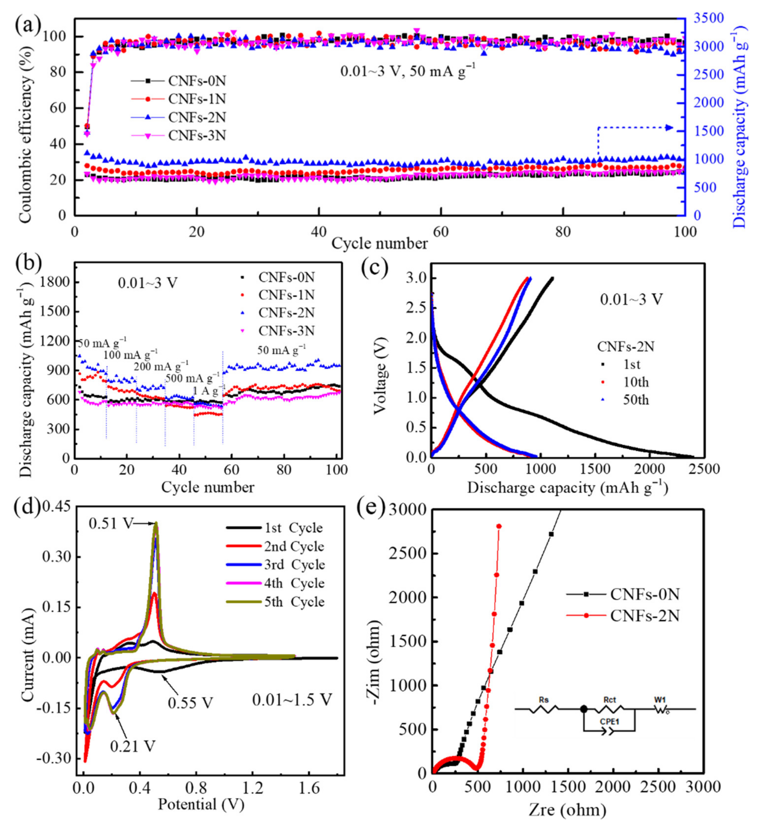
| CNFs-2N | 1.2 | 1108.9 (0.05 A g−1) | 954.3 (0.05 A g−1, 100 cycles) | 549.7 (1 A g−1) | This work |
Publisher’s Note: MDPI stays neutral with regard to jurisdictional claims in published maps and institutional affiliations. |
© 2022 by the authors. Licensee MDPI, Basel, Switzerland. This article is an open access article distributed under the terms and conditions of the Creative Commons Attribution (CC BY) license (https://creativecommons.org/licenses/by/4.0/).
Share and Cite
Liu, J.; Liu, Y.; Wang, J.; Wang, X.; Li, X.; Liu, J.; Nan, D.; Dong, J. Hierarchical and Heterogeneous Porosity Construction and Nitrogen Doping Enabling Flexible Carbon Nanofiber Anodes with High Performance for Lithium-Ion Batteries. Materials 2022, 15, 4387. https://doi.org/10.3390/ma15134387
Liu J, Liu Y, Wang J, Wang X, Li X, Liu J, Nan D, Dong J. Hierarchical and Heterogeneous Porosity Construction and Nitrogen Doping Enabling Flexible Carbon Nanofiber Anodes with High Performance for Lithium-Ion Batteries. Materials. 2022; 15(13):4387. https://doi.org/10.3390/ma15134387
Chicago/Turabian StyleLiu, Jun, Yuan Liu, Jiaqi Wang, Xiaohu Wang, Xuelei Li, Jingshun Liu, Ding Nan, and Junhui Dong. 2022. "Hierarchical and Heterogeneous Porosity Construction and Nitrogen Doping Enabling Flexible Carbon Nanofiber Anodes with High Performance for Lithium-Ion Batteries" Materials 15, no. 13: 4387. https://doi.org/10.3390/ma15134387