
Methodology of Leakage Prediction in Gasketed Flange Joints at Pipeline Deformations


Abstract
:1. Introduction
2. Materials and Methods
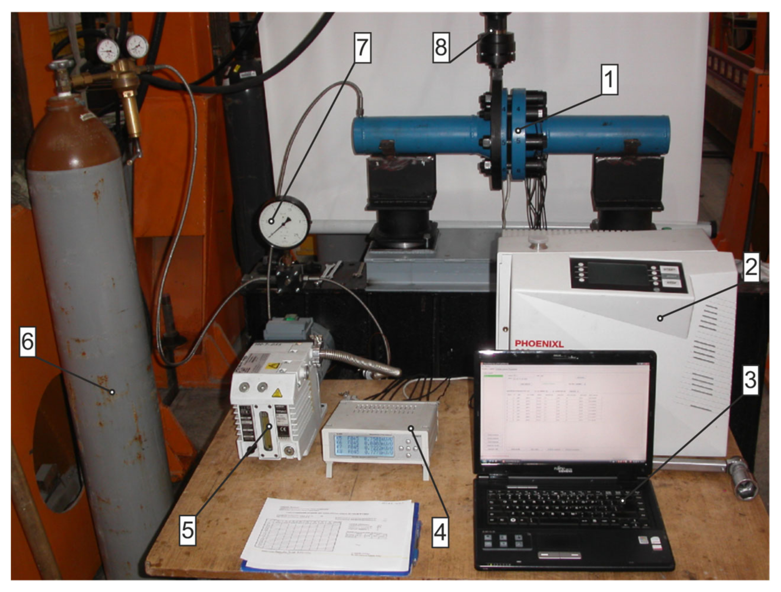
2.1. Experimental Method
- Displacement δ = 0.4 mm, force P = 20 kN;
- Displacement δ = 0.8 mm, force P = 70 kN;
- Displacement δ = 1.2 mm, force P = 120 kN.
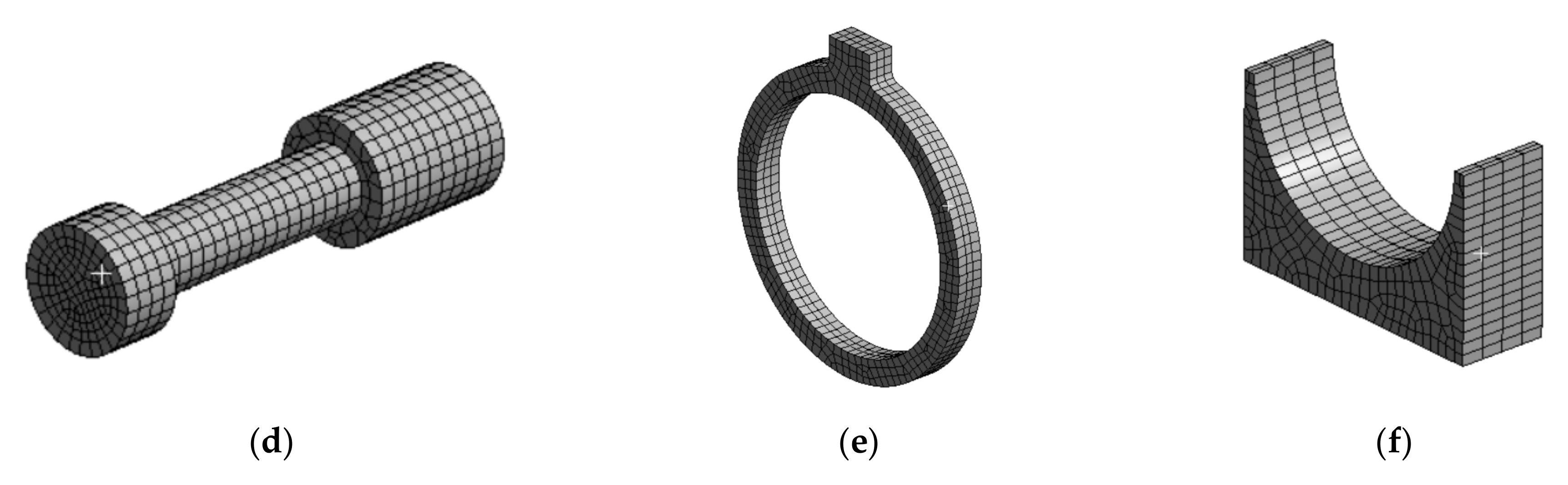
2.2. Numerical Method
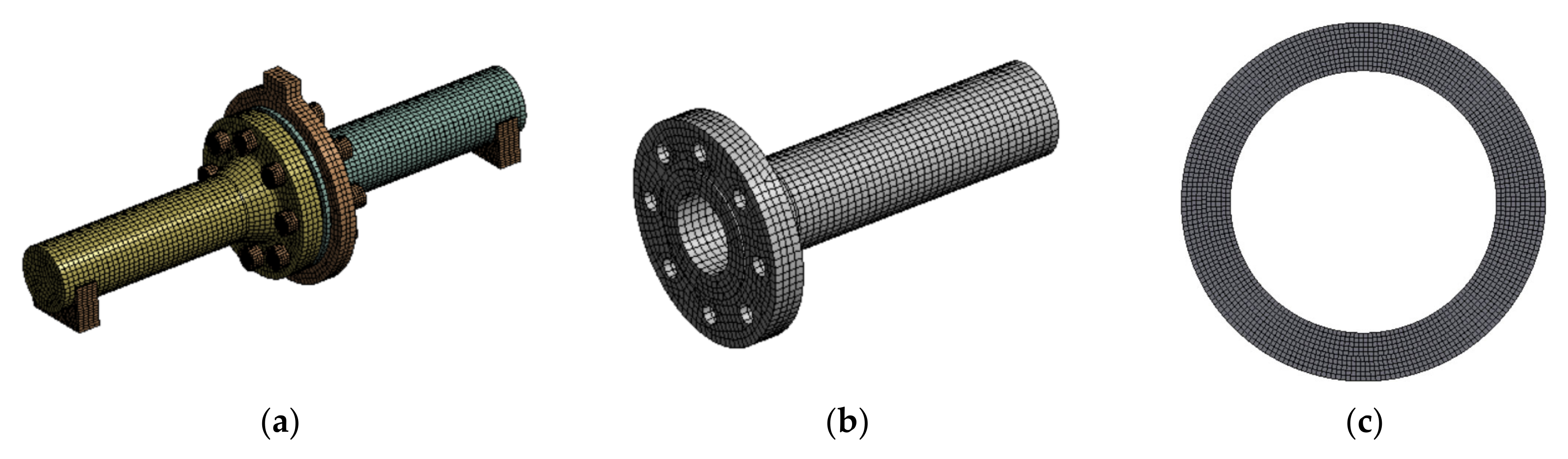
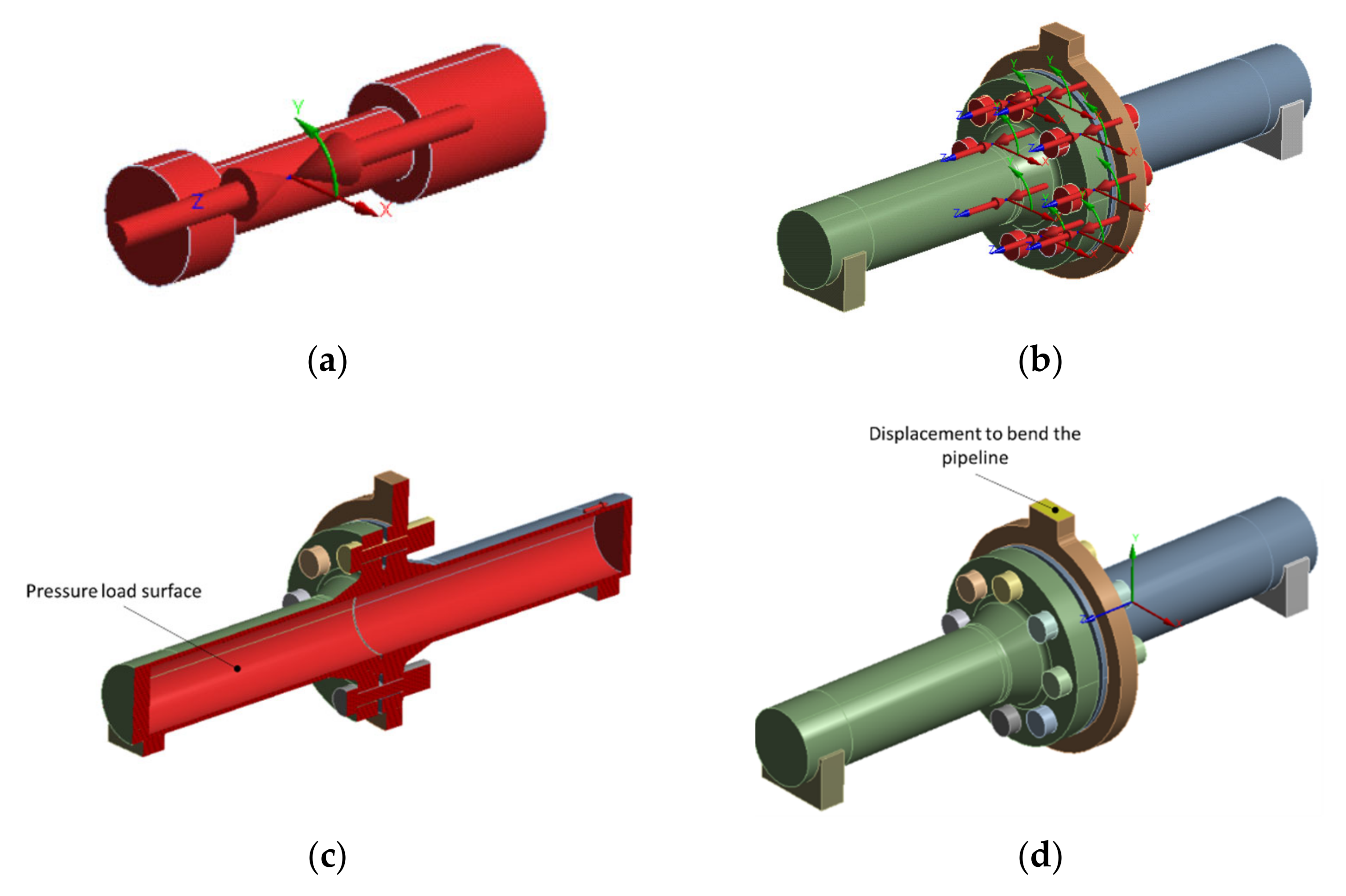
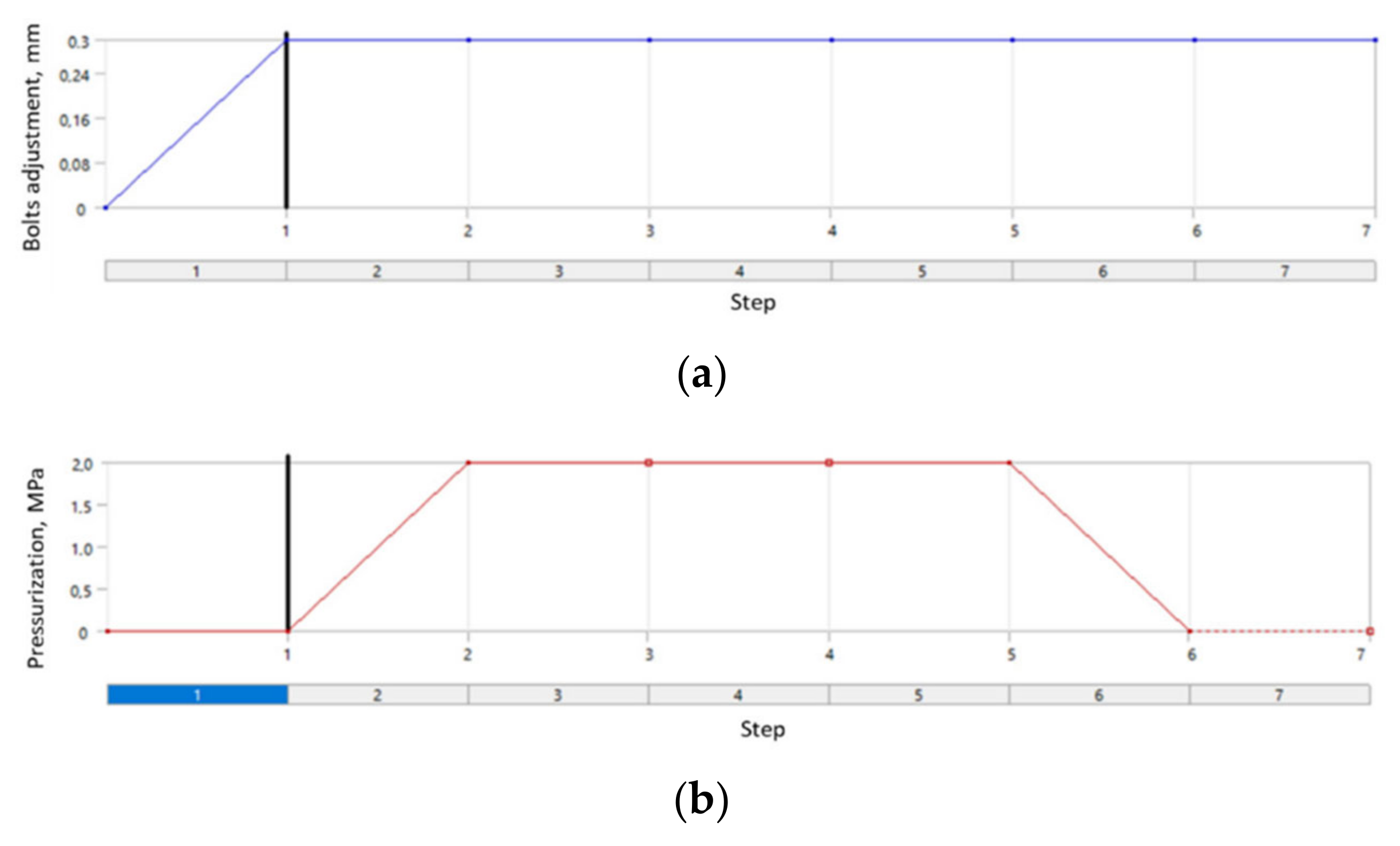
- Preload tension of the bolts (Figure 12a,b). In order to obtain an initial tension force of 52 kN per bolt, it was necessary to enter an appropriate value of the displacement. This value resulted directly from the shortening of the bolt section between the bolt head and the nut. The same approach was employed, e.g., in papers [12,13]. The initial value of the bolt head and nut overlapping the flange-bearing surface, ensuring the bolt-tension value of 52 kN, was 0.32 mm.
- Internal pipeline pressure of 2 MPa. Figure 12c shows the internal surfaces that the pressure was applied to. In this case, the internal pipeline walls and internal lateral surface of the gasket are the load surfaces.
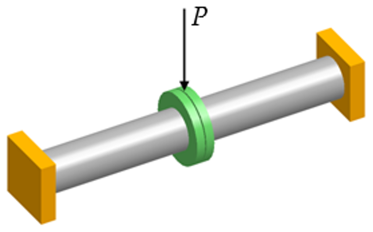
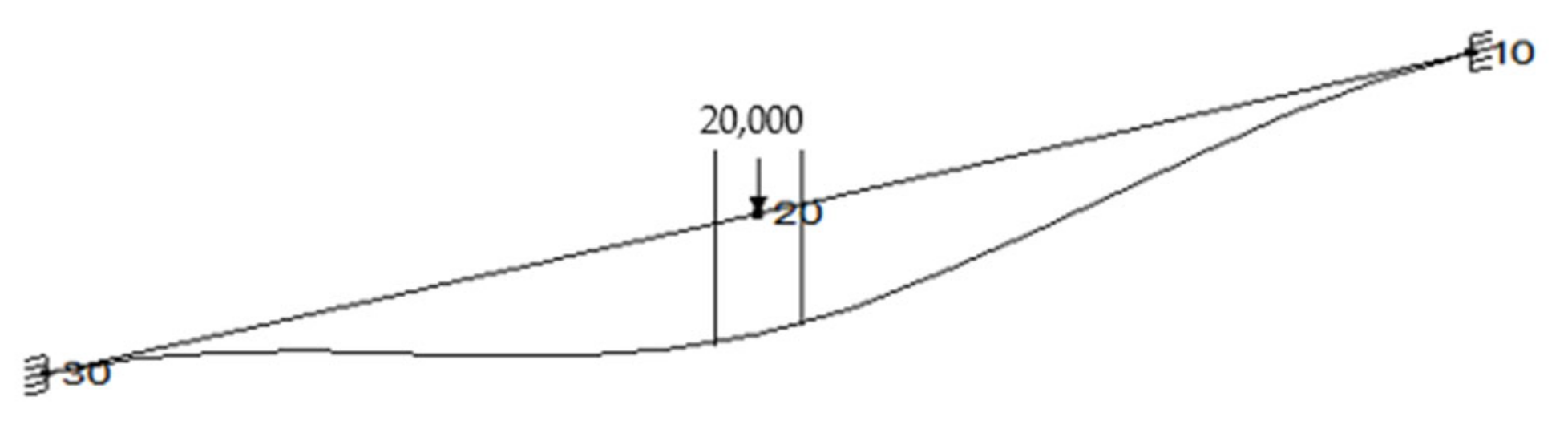
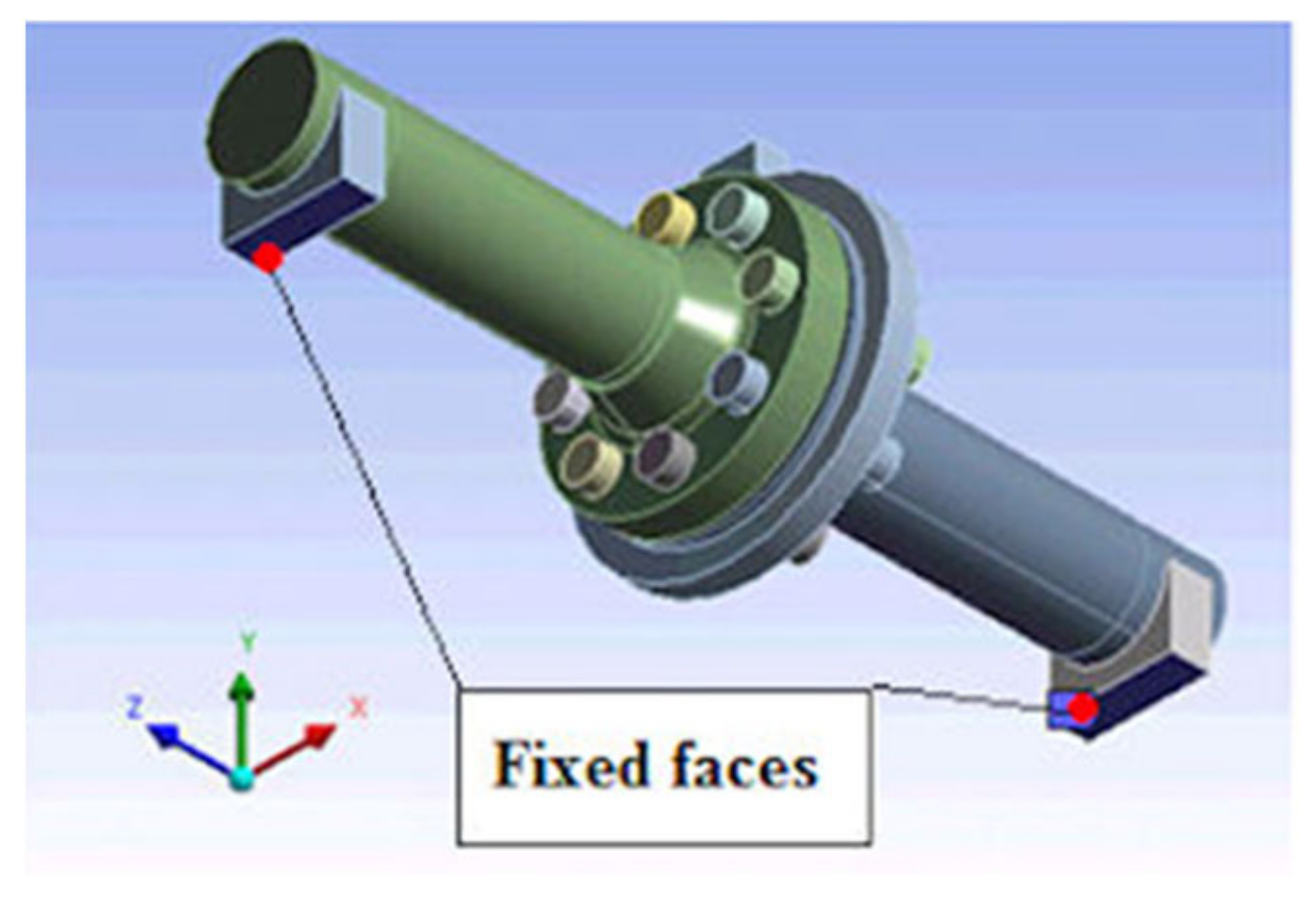
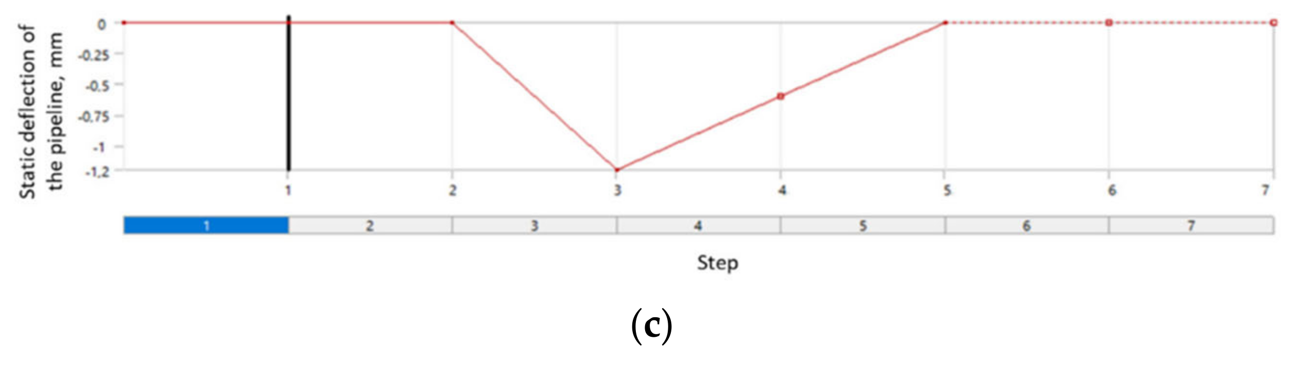
- Displacement causing the pipeline bending (Figure 12d). The surface where the displacement vector was defined was the place of the ring connection with a hydraulic exciter in the test stand. A bending simulation was carried out for the following three displacement (pipeline deflection) options: 1.2 mm, 0.8 mm, and 0.4 mm.
3. Results and Discussion
3.1. Experimental Test Results
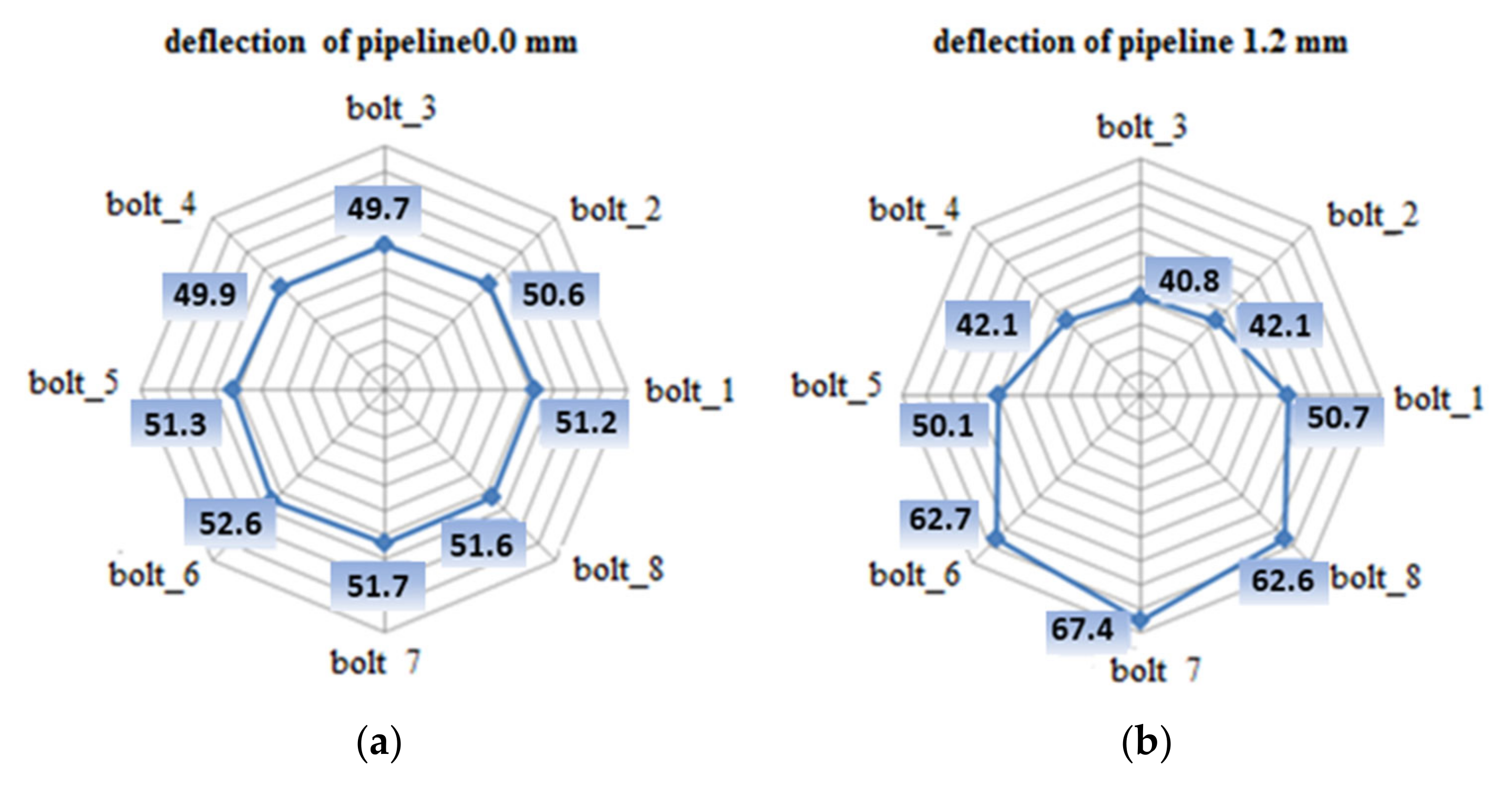
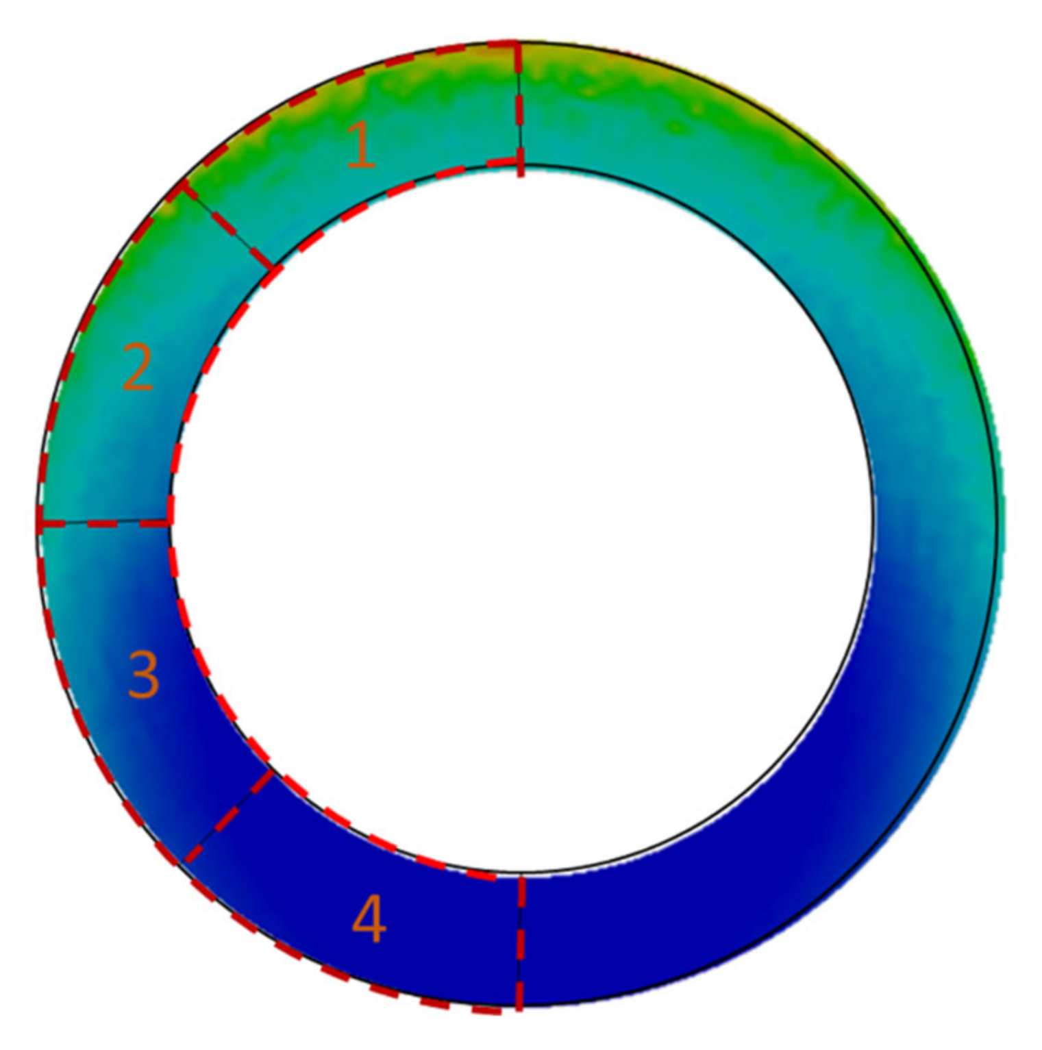
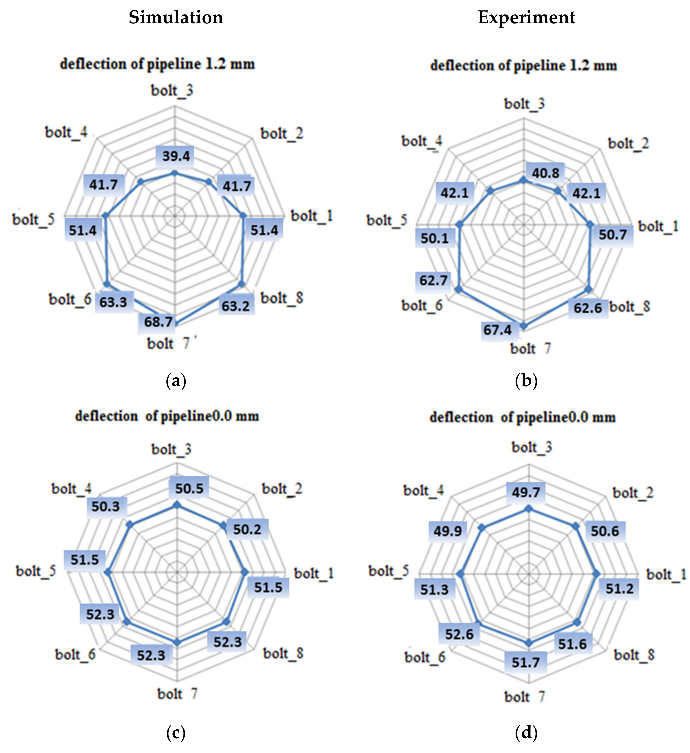
- Zone 1, in the area of bolts 2, 3, and 4, where the pipeline deflection and the resulting rotation of the flanges cause unloading of the bolts;
- Zone 2, located at the level of the pipeline-bending axis, where bolts 1 and 5 are located;
- Zone 3, where tension in the bolts increases as a result of deflection, i.e., the location of bolts 6, 7, and 8.
3.2. Computation Results and Discussion
- σi—average contact pressure in particular zone;
- σm—mean contact pressure obtained at gasket assembly;
- Li—leakage level calculated in the particular zone;
- LT—total leakage level from all zones.
4. Conclusions
Author Contributions
Funding
Institutional Review Board Statement
Informed Consent Statement
Data Availability Statement
Conflicts of Interest
References
- Abid, M.; Nash, D.H. A parametric study of metal-to-metal contact flanges with optimized geometry for safe stress and no-leak conditions. Int. J. Press. Vessel Pip. 2004, 81, 67–74. [Google Scholar] [CrossRef] [Green Version]
- Jaszak, P. The elastic serrated gasket of the flange bolted joints. Int. J. Press. Vessel Pip. 2019, 176, 103954. [Google Scholar] [CrossRef]
- Jaszak, P. Modelling of the elastic properties of compressed expanded graphite—A material used in spiral wound gaskets. Int. J. Press. Vessel Pip. 2020, 187, 104158. [Google Scholar] [CrossRef]
- Bickford, J.H. Handbook of Bolts and Bolted Joints; Marcel & Dekker Inc.: New York, NY, USA, 1998. [Google Scholar]
- Abid, M.; Rauf, A.; Khushnood, S. Nonlinear finite element analysis of gasketed flange joints under combined internal pressure and different thermal loading conditions. In Proceedings of the Failure of Engineering Materials & Structures Conference, University of Engineering and Technology, Taxila, Pakistan, 22–23 October 2007. [Google Scholar]
- Estrada, H.; Parsons, I.D. Strength and leakage finite element analysis of a GFRP flange joint. Int. J. Press. Vessel Pip. 1999, 76, 543–550. [Google Scholar] [CrossRef]
- Cao, B.; Duan, C.; Xu, H. 3-D finite element analysis of bolted flange joint considering gasket nonlinearity. In Analysis of Bolted Joints, Proceedings of the ASME Pressure Vessels and Piping Conference, Boston, MA, USA, 1–5 August 1999; Volume 382, pp. 121–126.
- Joshi, D.; Mahadevan, P.; Marathe, A.; Chatterjee, A. Unimportance of geometric nonlinearity in analysis of flanged joints with metal-to-metal contact. Int. J. Press. Vessel Pip. 2007, 84, 405–411. [Google Scholar] [CrossRef]
- Grzejda, R. Determination of bolt forces and normal contact pressure between elements in the system with many bolts for its assembly conditions. Adv. Sci. Technol. Res. J. 2019, 13, 116–121. [Google Scholar] [CrossRef]
- Grzejda, R. Impact of nonlinearity on bolt forces in multi-bolted joints: A case of the assembly stage. Sci. Iran. B 2019, 26, 1299–1306. [Google Scholar] [CrossRef] [Green Version]
- Grzejda, R. Finite element modelling of a pair of flexible elements contact preloaded and externally loaded with an arbitrary force. Adv. Sci. Technol. Res. J. 2020, 14, 118–124. [Google Scholar] [CrossRef]
- Murali Krishna, M.; Shunmugam, M.S.; Siva Prasad, N. A study on sealing performance of bolted flange joints with gasket using finite element analysis. Int. J. Press. Vessel Pip. 2007, 84, 349–357. [Google Scholar] [CrossRef]
- Ryś, J.; Malara, P.; Barski, M. Numerical analysis of the gasket stiffness influence on the bold load in flanged joints. Tech. Trans. Mech. 2011, 108, 93–112. (In Polish) [Google Scholar]
- Abid, M.; Nash, D.H. Comparative study of the behavior of conventional gasketed and compact on non-gasketed flanged pipe joint under bolt up and operating conditions. Int. J. Press. Vessel Pip. 2003, 80, 831–841. [Google Scholar] [CrossRef]
- Zhou, W.; Ai, S.; Chen, M.; Zhang, R.; He, R.; Pei, Y.; Fang, D. Preparation and thermodynamic analysis of the porous ZrO2/(ZrO2 + Ni) functionally graded bolted joint. Compos. Part B Eng. 2015, 82, 13–22. [Google Scholar] [CrossRef]
- Zhou, W.; Zhang, R.; Ai, S.; He, R.; Pei, Y.; Fang, D. Load distribution in threads of porous metal–ceramic functionally graded composite joints subjected to thermomechanical loading. Compos. Struct. 2015, 134, 680–688. [Google Scholar] [CrossRef] [Green Version]
- DIN 28091-1: 1995-09; Technical Delivery Conditions for Gasket Sheets, Part 1: Gasket Materials; General Requirements. German Institute for Standardisation Registered Association: Berlin, Germany, 1995.
- DIN 28091-2: 1995-09; Technical Delivery Conditions for Gasket Sheets, Part 2: Fibre-Based Gasket Materials (FA); Requirements and Testing. German Institute for Standardisation Registered Association: Berlin, Germany, 1995.
- EN 13555: 2001; Flanges and Their Joints, Gasket Parameters and Test Procedures Relevant to the Design Rules for Gasketed Circular Flange Connections. European Committee for Standardization: Brussels, Belgium, 2001.
- PN-EN 13480-1:2017-10; Metallic Industrial Piping, Part 1: General. Polish Committee for Standardization: Warsaw, Poland, 2017.
- PN-EN 13445-1:2021-10; Unfired Pressure Vessels, Part 1: General. Polish Committee for Standardization: Warsaw, Poland, 2021.
- Skrzat, A. Modeling of Linear and Nonlinear Problems of Solid Mechanics and Heat Flows in the ABAQUS Program; Oficyna Wydawnicza Politechniki Rzeszowskiej: Rzeszów, Poland, 2010. (In Polish) [Google Scholar]


| No. | Parameter | Symbol | Value | Unit |
|---|---|---|---|---|
| Operating parameters | ||||
| 1. | Pressure | p | 2 | MPa |
| 2. | Fluid temperature | T | 20 | °C |
| Flanges | ||||
| 3. | External diameter | D | 275 | mm |
| 4. | Pitch circle diameter | Db | 210 | mm |
| 5. | Pipe diameter | Dp | 100 | mm |
| 6. | Flange thickness | tf | 38.5 | mm |
| 7. | Material | - | 1.4301 | - |
| Pipe | ||||
| 8. | External diameter | Dpe | 114.2 | mm |
| 9. | Wall thickness | ts | 2.6 | mm |
| 10. | Material | - | 1.4301 | - |
| Gasket | ||||
| 11. | Outer diameter | do | 152 | mm |
| 12. | Inner diameter | di | 112 | mm |
| 13. | Gasket thickness | tg | 1 and 2 | mm |
| Bolts | ||||
| 14. | Number of bolts | nb | 8 | - |
| 15. | Bolt strength | bs | 12.9 | - |
| 16. | Bolt diameter | M | 24 | mm |
| L (mm) | σ1 (MPa) | δ (mm) |
|---|---|---|
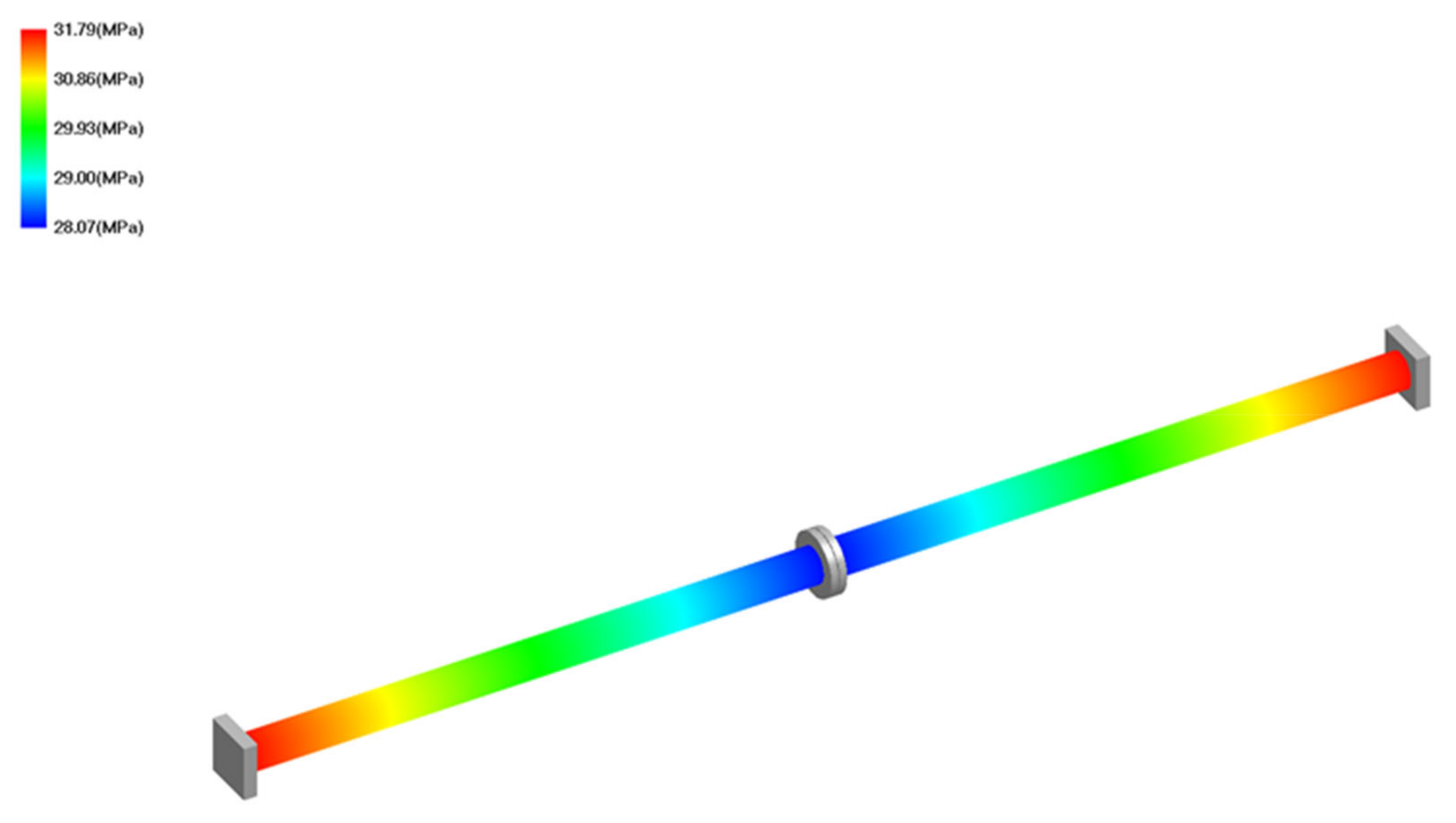
| 1850 | 31.8 | 0.4 |
| 2250 | 35.86 | 0.8 |
| 2500 | 38.76 | 1.2 |
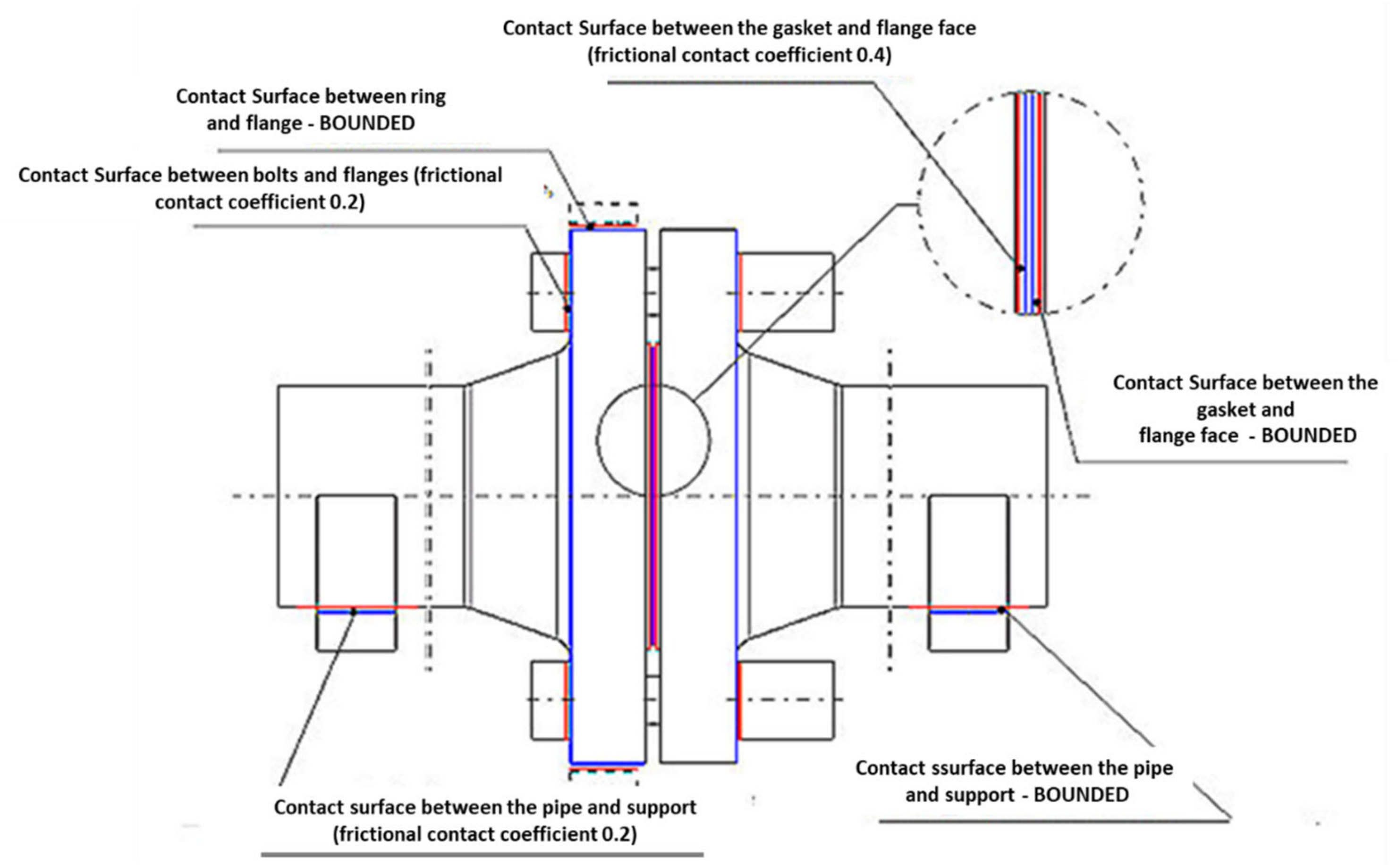
| Elements in Contact | Kind of Contact | Contact Elements |
|---|---|---|
| Gasket/Left flange | “Frictional” | CONTA/TARGET |
| Gasket/Right flange | “Bounded” | – |
| Ring/Left flange | “Bounded” | – |
| Support/Left flange | “Frictional” | CONTA/TARGET |
| Support/Right flange | “Bounded” | – |
| Bolts/Flanges | “Frictional” | CONTA/TARGET |
| Bolt’s Tension | Number of Bolts | ||||||||
|---|---|---|---|---|---|---|---|---|---|
| 1 | 2 | 3 | 4 | 5 | 6 | 7 | 8 | ||
| Deformation | kN | kN | kN | kN | kN | kN | kN | kN | |
| 1.2 | mm | 50.7 | 42.1 | 40.8 | 42.1 | 50.1 | 62.7 | 67.4 | 62.6 |
| 0.8 | mm | 50.5 | 48.4 | 46.2 | 48.7 | 50.6 | 54.9 | 58.3 | 54.7 |
| 0.4 | mm | 50.2 | 50.6 | 50.8 | 51.3 | 50.3 | 52.0 | 52.7 | 51.8 |
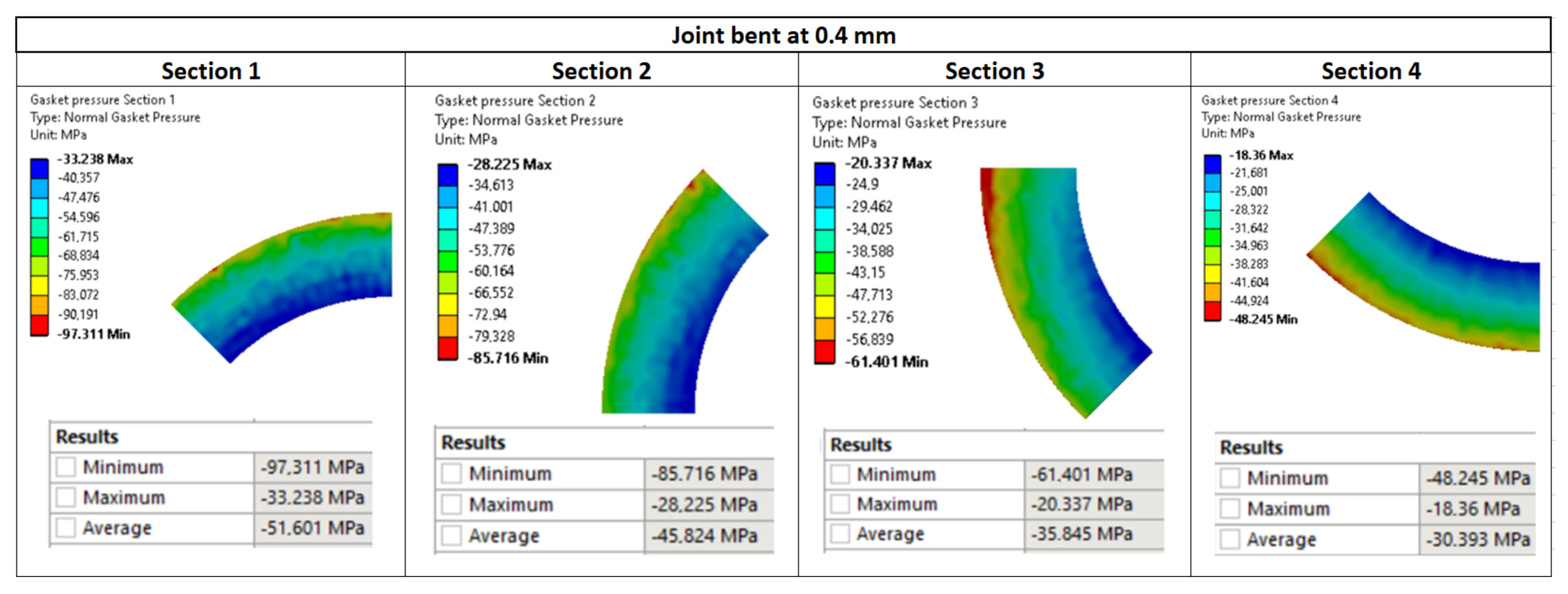
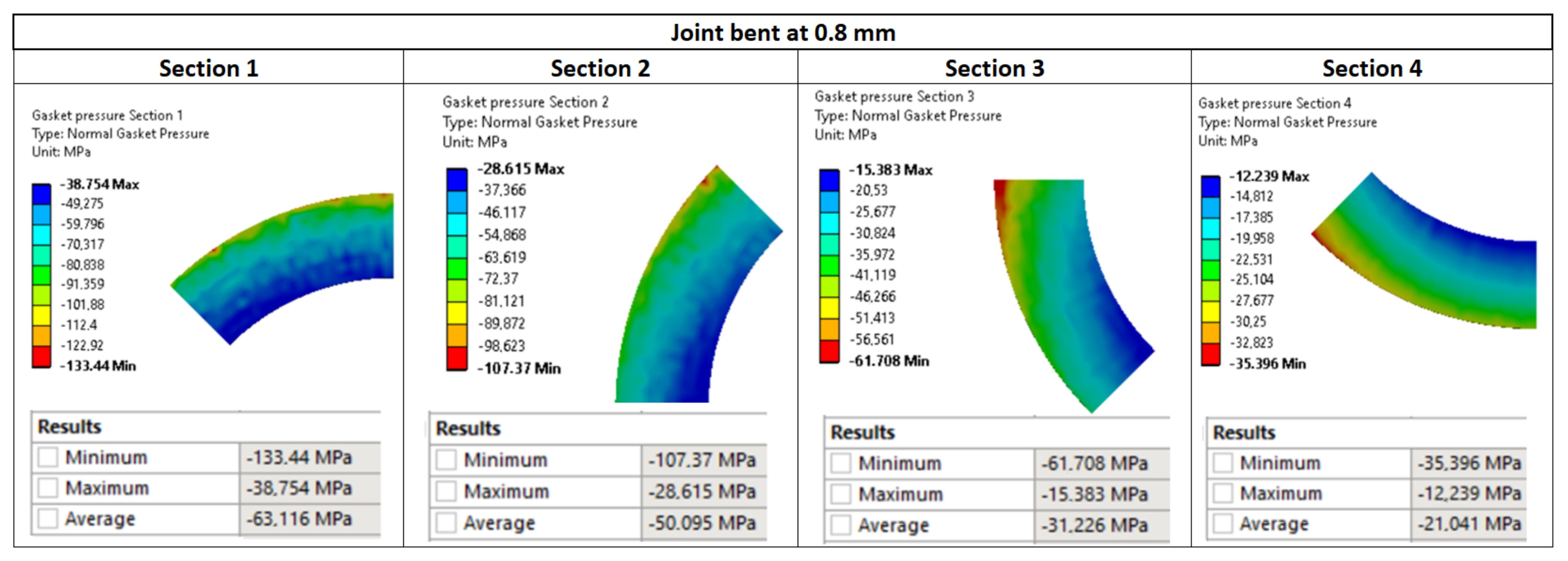
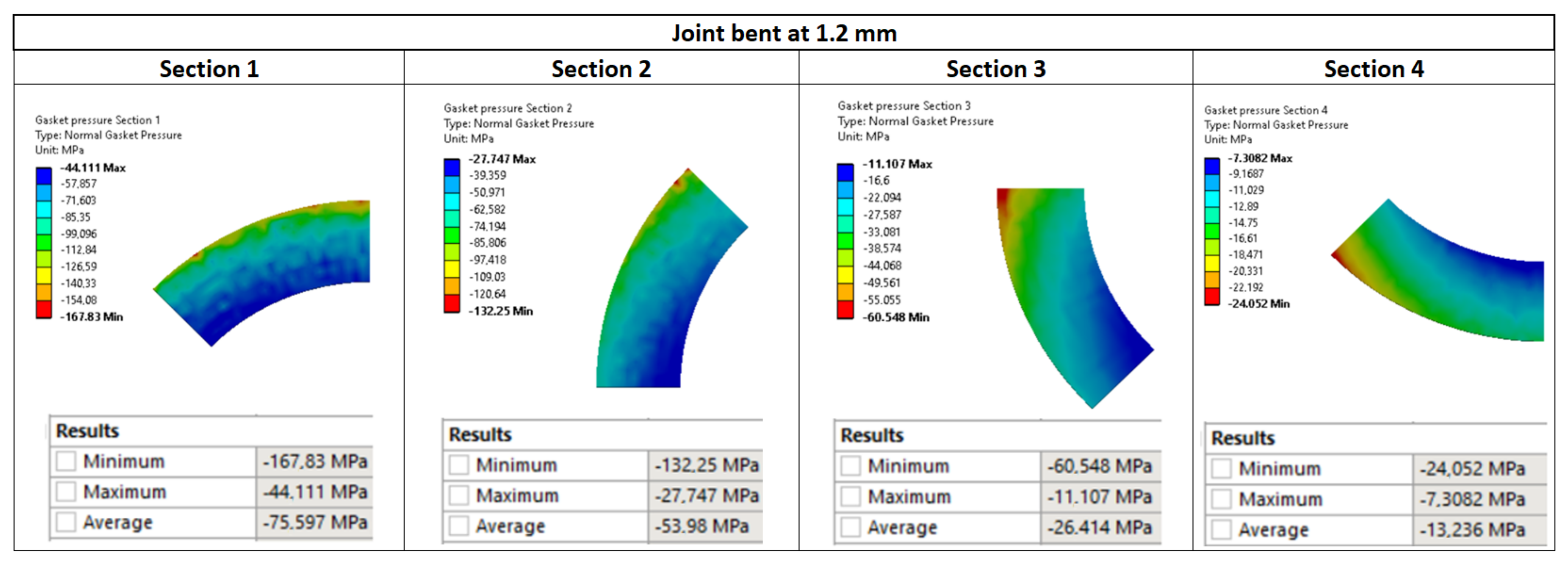
| Deflection 1.2 mm | Deflection 0.8 mm | Deflection 0.4 mm | ||||||
|---|---|---|---|---|---|---|---|---|
| Section | Stress | Leakage | Section | Stress | Leakage | Section | Stress | Leakage |
| – | MPa | mg/(s·m) | – | MPa | mg/(s·m) | – | MPa | mg/(s·m) |
| 1. | 75.6 | 6.84 × 10⁻⁵ | 1. | 63.12 | 0.000323 | 1. | 47.03 | 0.00202 |
| 2. | 54 | 0.001238 | 2. | 50.9 | 0.002059 | 2. | 43.89 | 0.002205 |
| 3. | 26.4 | 0.004203 | 3. | 31.23 | 0.003396 | 3. | 37.67 | 0.002677 |
| 4. | 13.23 | 0.0101 | 4. | 21.04 | 0.005606 | 4. | 34.84 | 0.002956 |
| Total | 1.56 × 10⁻² mg/(s·m) | Total | 1.14 × 10⁻² mg/(s·m) | Total | 9.86 × 10⁻³ mg/(s·m) | |||
Publisher’s Note: MDPI stays neutral with regard to jurisdictional claims in published maps and institutional affiliations. |
© 2022 by the authors. Licensee MDPI, Basel, Switzerland. This article is an open access article distributed under the terms and conditions of the Creative Commons Attribution (CC BY) license (https://creativecommons.org/licenses/by/4.0/).
Share and Cite
Jaszak, P.; Skrzypacz, J.; Borawski, A.; Grzejda, R. Methodology of Leakage Prediction in Gasketed Flange Joints at Pipeline Deformations. Materials 2022, 15, 4354. https://doi.org/10.3390/ma15124354
Jaszak P, Skrzypacz J, Borawski A, Grzejda R. Methodology of Leakage Prediction in Gasketed Flange Joints at Pipeline Deformations. Materials. 2022; 15(12):4354. https://doi.org/10.3390/ma15124354
Chicago/Turabian StyleJaszak, Przemysław, Janusz Skrzypacz, Andrzej Borawski, and Rafał Grzejda. 2022. "Methodology of Leakage Prediction in Gasketed Flange Joints at Pipeline Deformations" Materials 15, no. 12: 4354. https://doi.org/10.3390/ma15124354