
The Influence of Heat Treatment on the Mechanical Properties and Corrosion Resistance of the Ultrafine-Grained AA7075 Obtained by Hydrostatic Extrusion

 , ,
, ,  , and
, and
Abstract
:1. Introduction
2. Materials and Methods
- CG, a coarse-grained precipitation-strengthened sample used as a reference material, solution heat-treated with T6 aging following hydrostatic extrusion to maintain the size and location of intermetallic inclusions.
- HE, an ultrafine-grained sample naturally aged for 180 days following hydrostatic extrusion.
- HT1, an ultrafine-grained sample precipitation strengthened following hydrostatic extrusion (artificially aged at 100 °C for 24 h).
- HT2, an ultrafine-grained sample precipitation strengthened following hydrostatic extrusion (artificially aged at 120 °C for 24 h).
3. Results
3.1. Microstructure
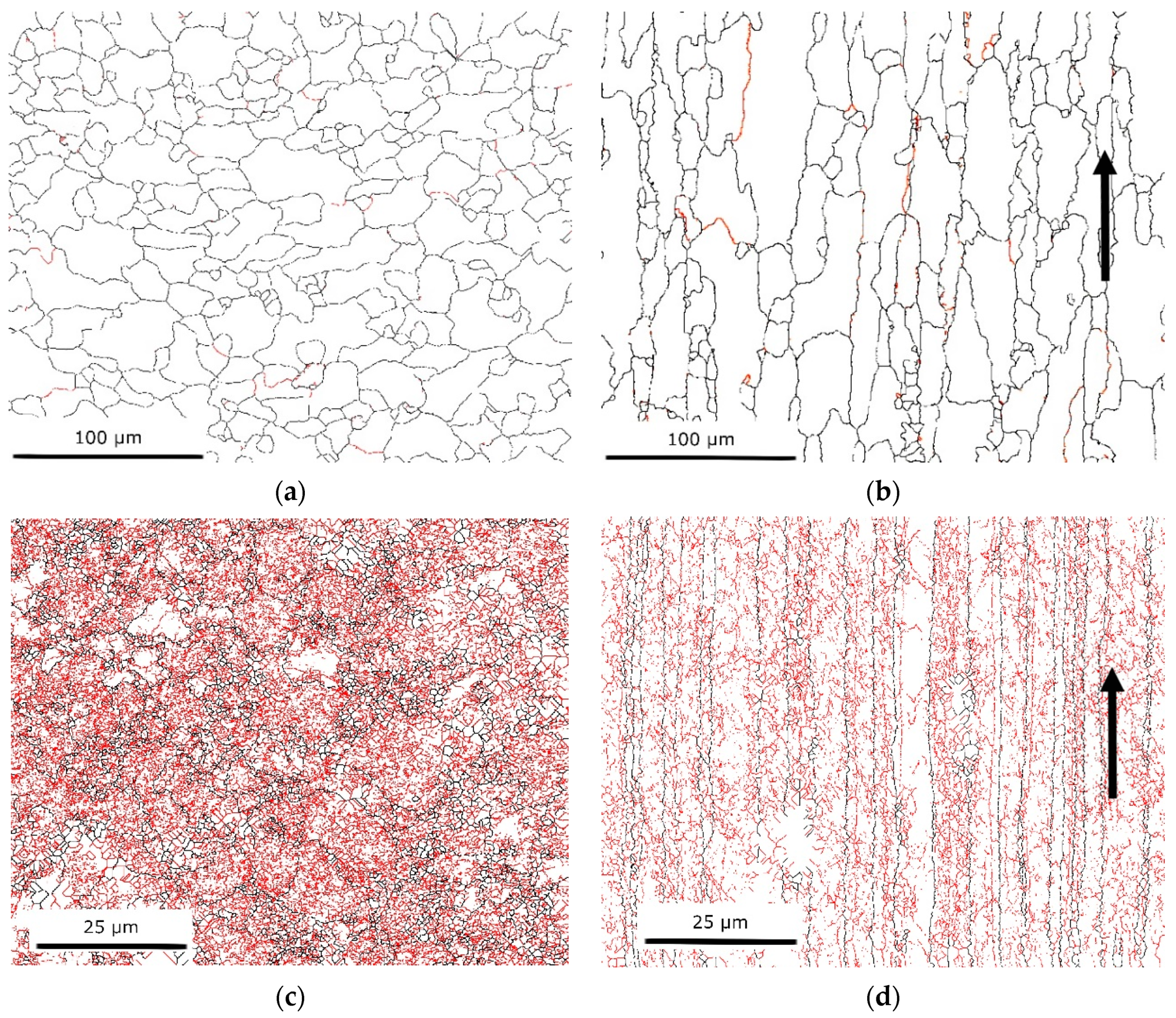
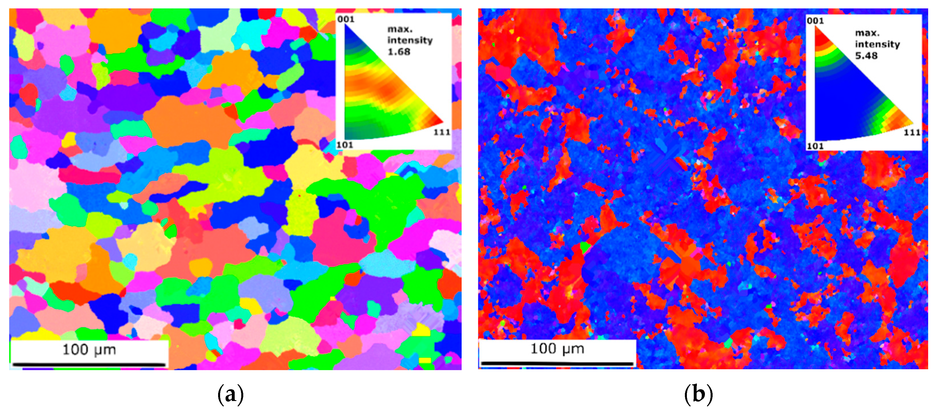
3.1.1. SEM/EBSD
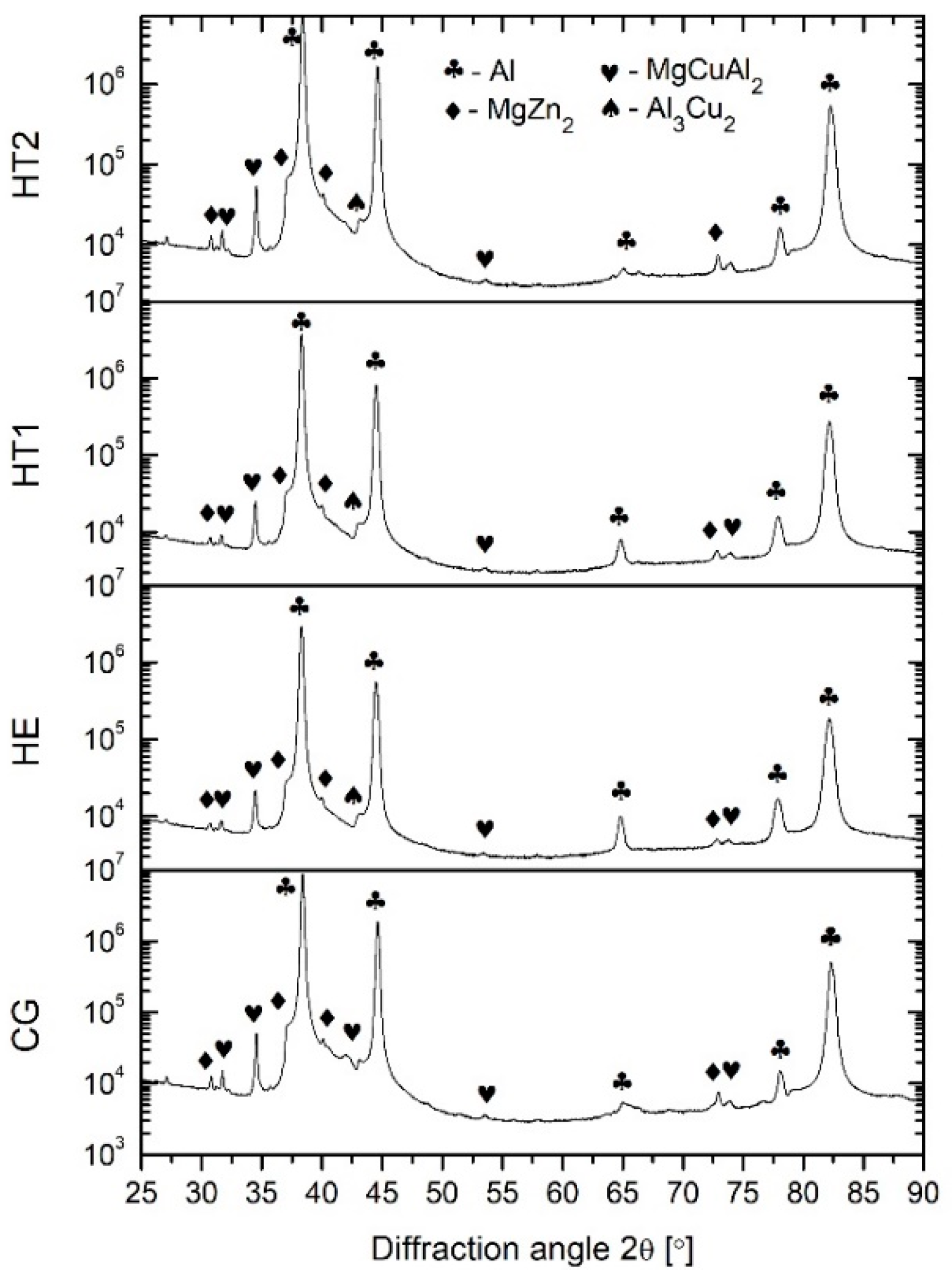
3.1.2. XRD
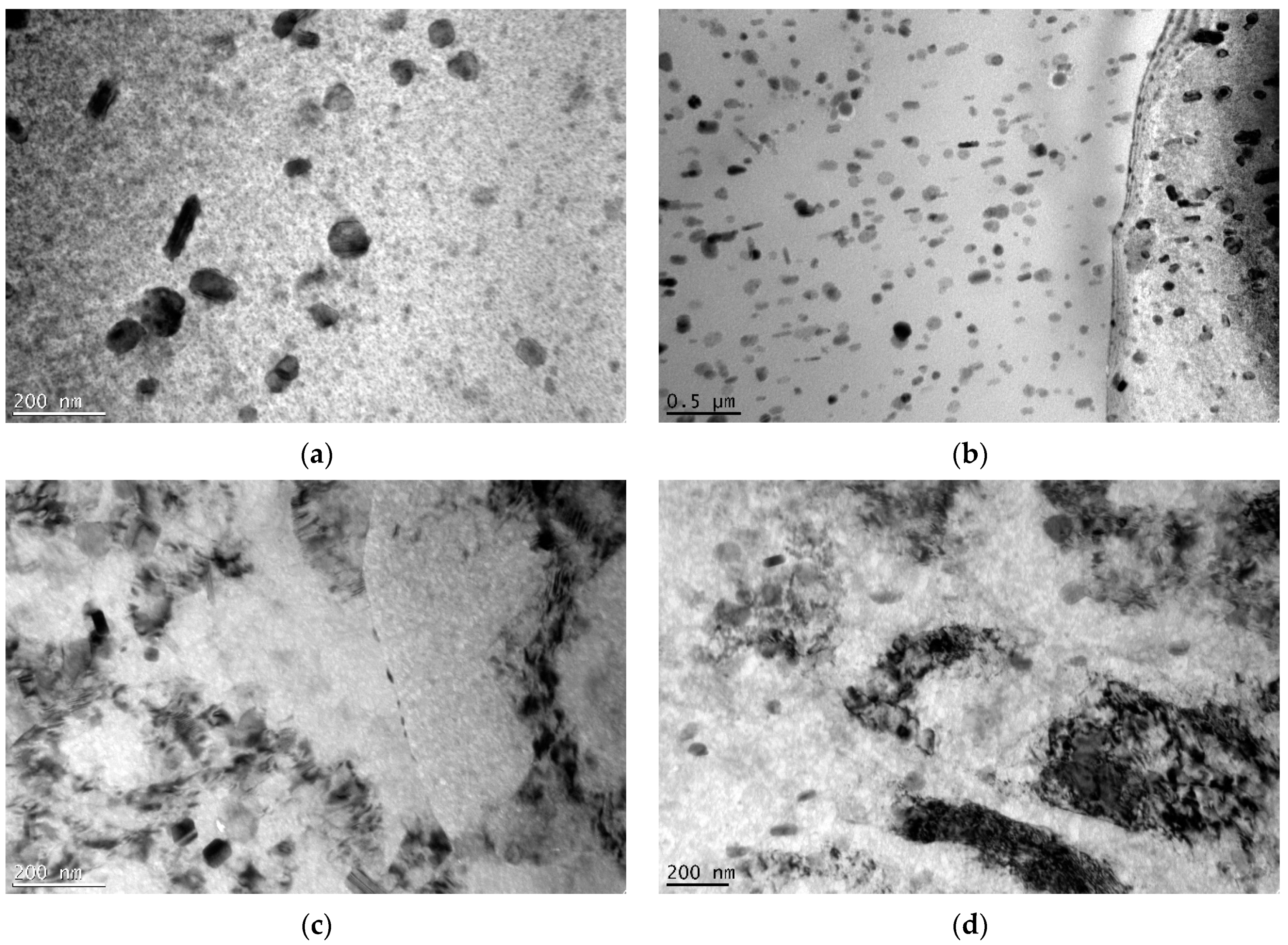
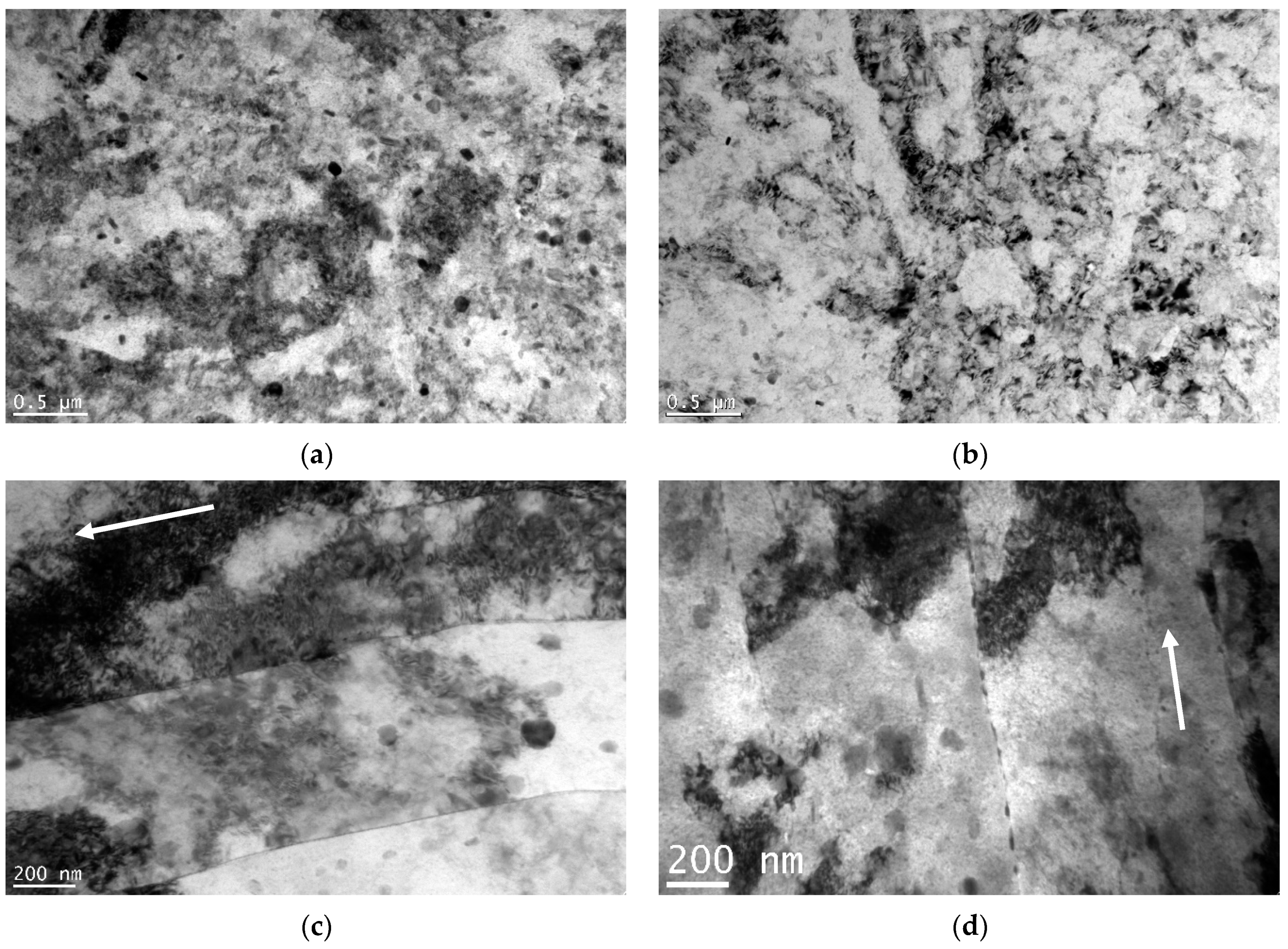
3.1.3. TEM
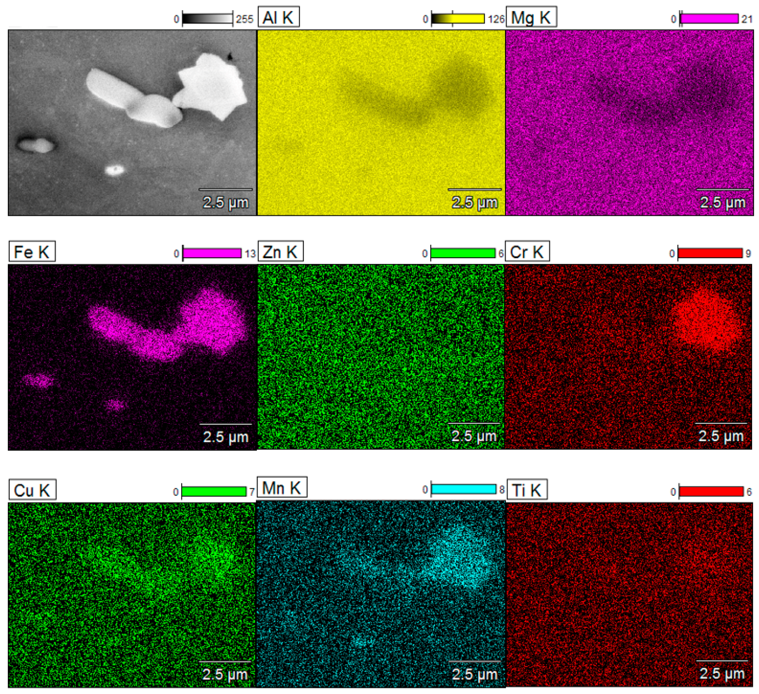
3.1.4. SEM/EDS
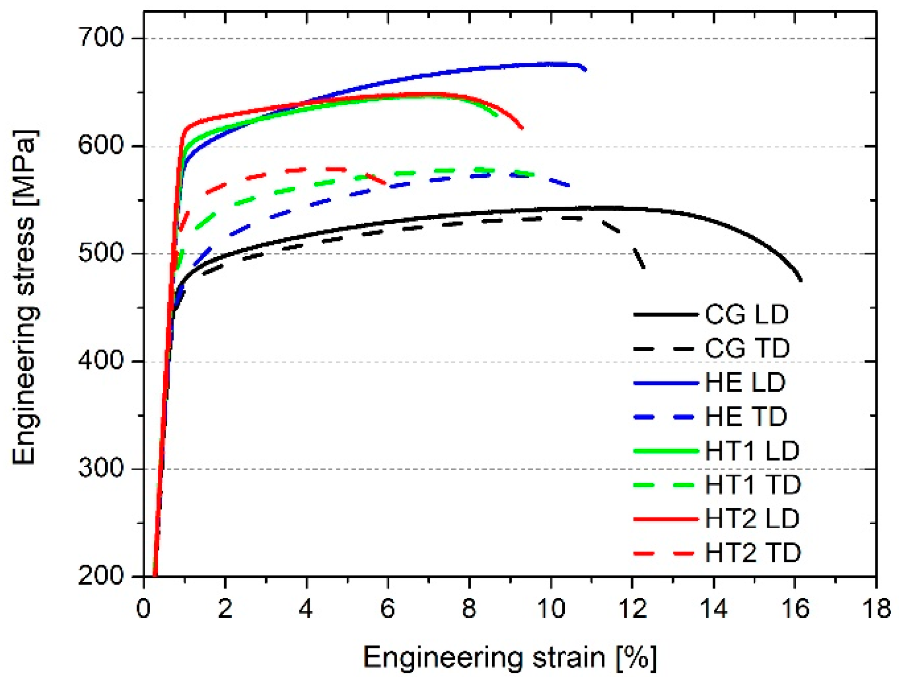
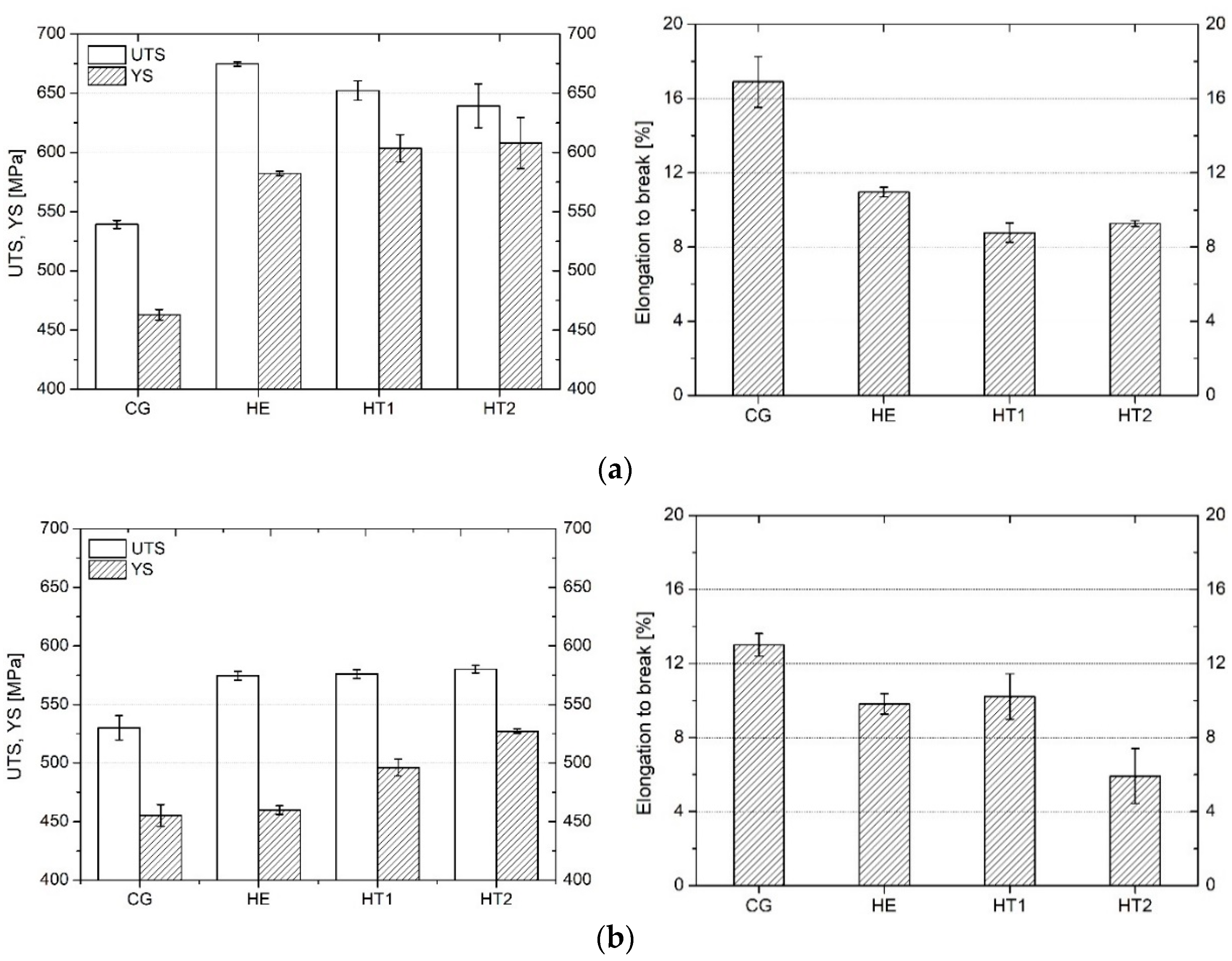
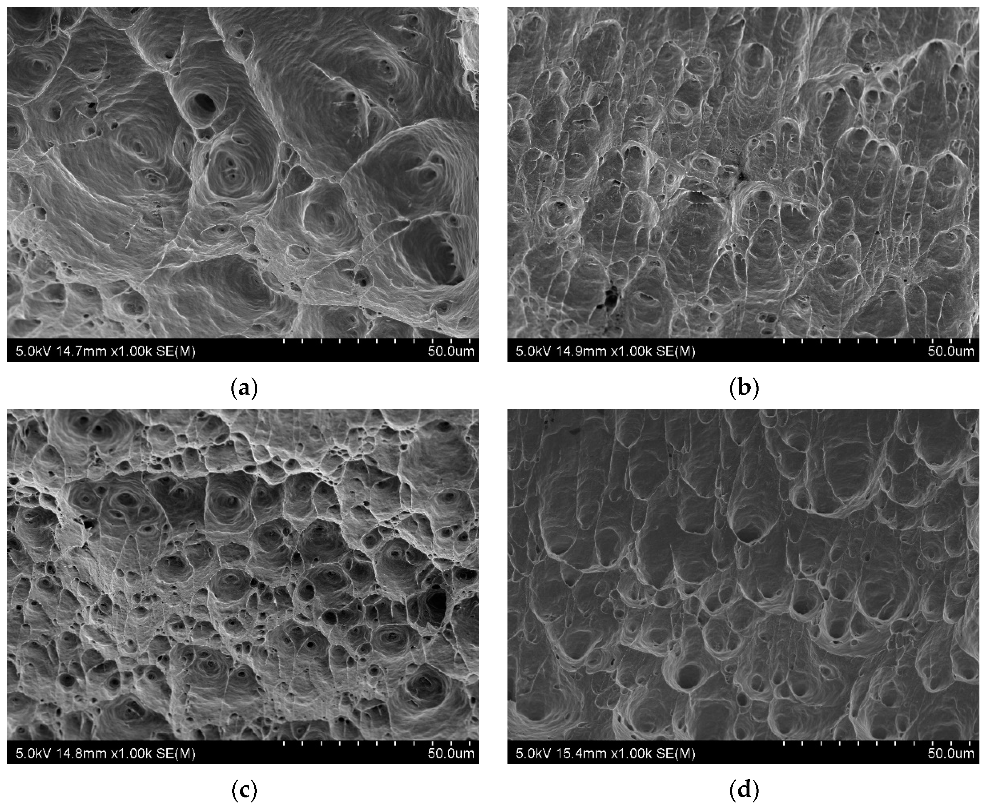
3.2. Mechanical Properties
3.3. Corrosion
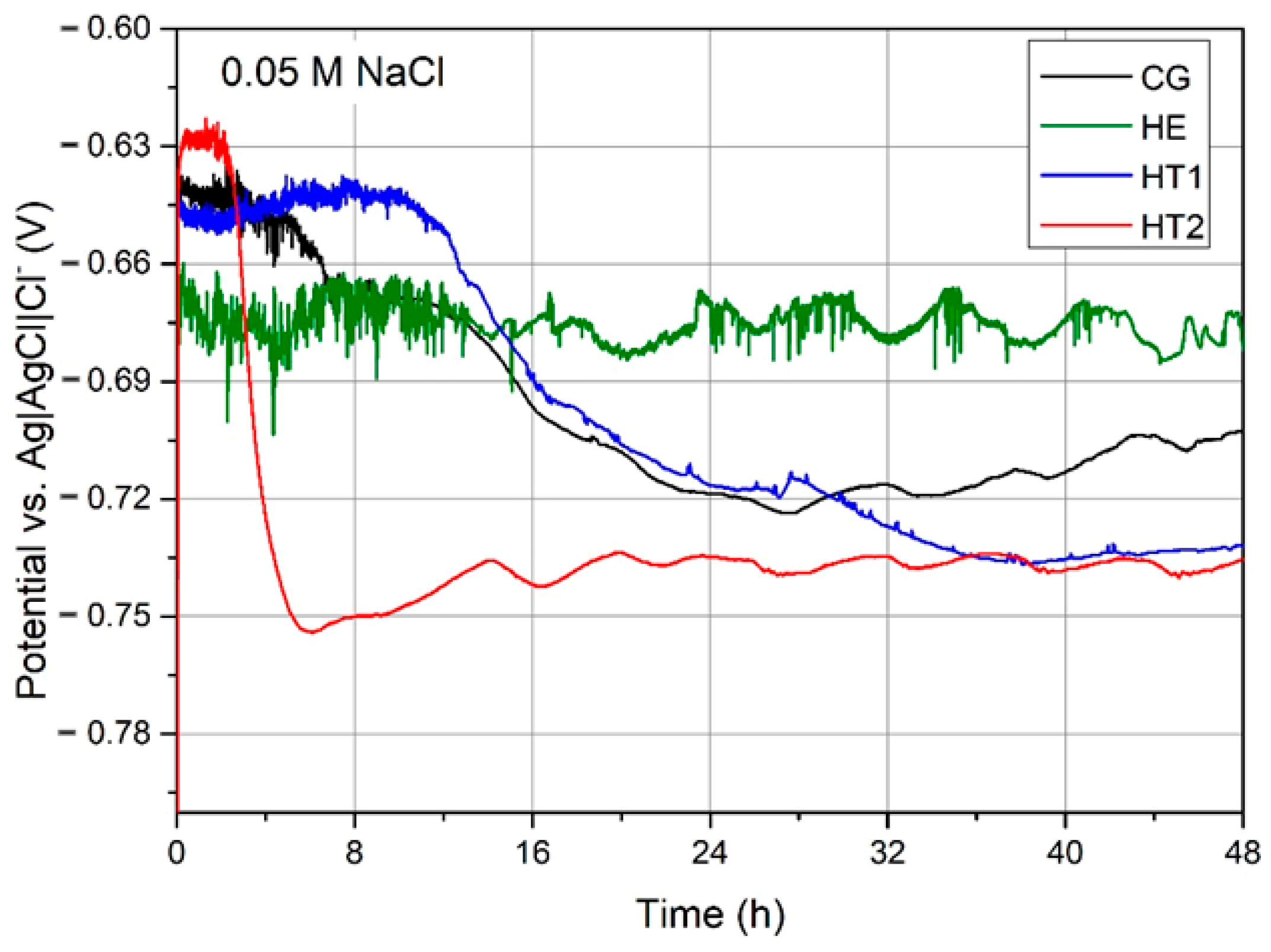
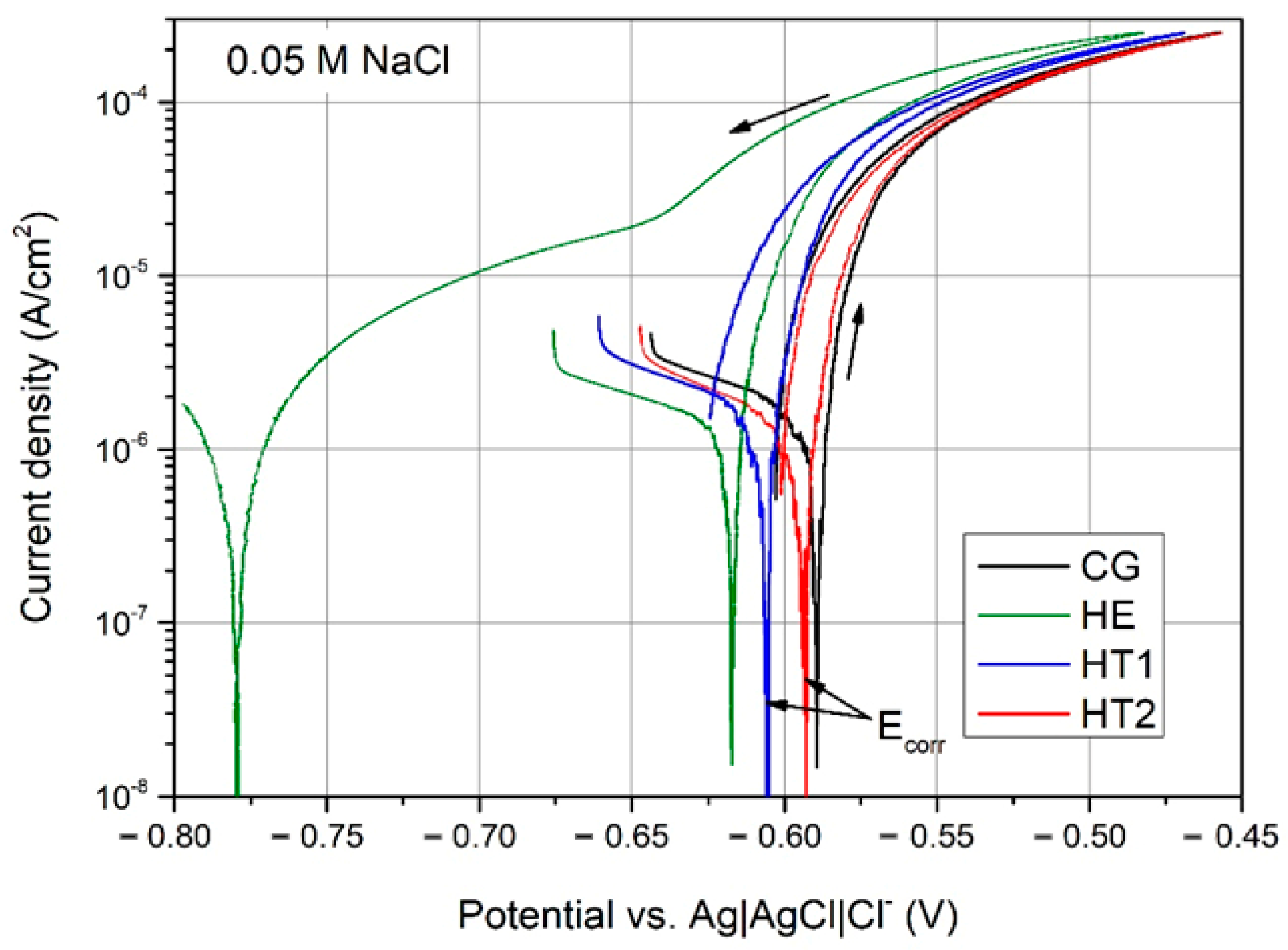
3.3.1. Electrochemical Properties
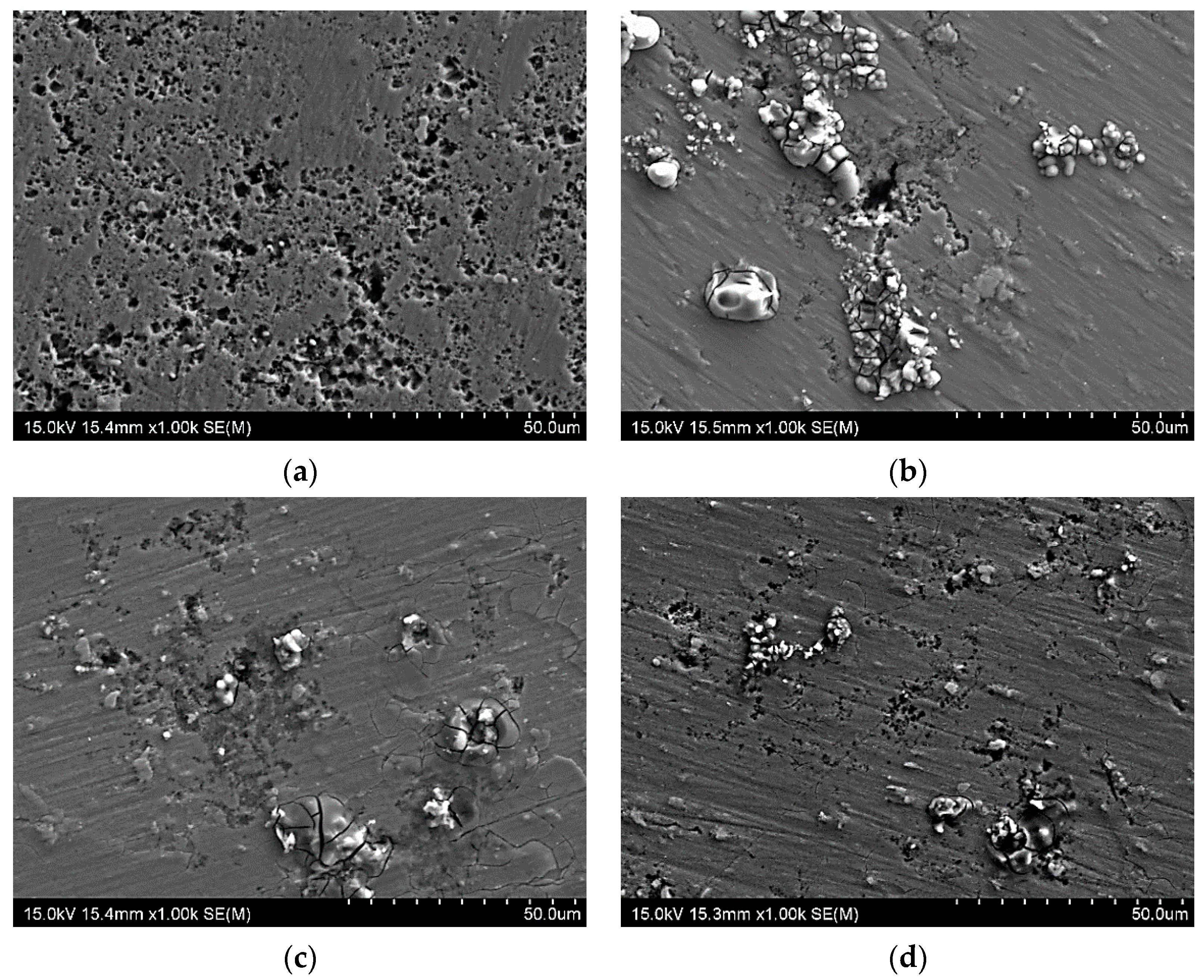
3.3.2. Postcorrosion Morphology
4. Discussion
4.1. Microstructural Evolution through Hydrostatic Extrusion with Subsequent Aging
4.2. Influence of Microstructural Evolution on Mechanical Properties
4.3. Influence of Microstructural Evolution on Corrosion Resistance
5. Conclusions
- Hydrostatic extrusion with an equivalent strain of ε = 1.4 resulted in grain refinement from 17 to 1.3 µm. A microstructure consisting of fibrous grains oriented in the <001> and <111> directions with a fraction of LAGBs of 76% was obtained.
- As a result of thermomechanical treatment, an increase in tensile strength of up to 100 MPa was obtained when compared to the CG T6 state. Hydrostatic extrusion caused a noticeable anisotropy of the mechanical properties, as differences in tensile strength between longitudinal and transverse directions were in the range of 60–100 MPa.
- Artificial aging caused an increase in the size of MgZn2 precipitates within the microstructure, and led to improved corrosion resistance due to changes in the chemical composition of the matrix. The differences in mechanical strength in relation to the aging temperature were not significant due to the location of precipitates at the grain boundaries, which were not effective in strengthening the material.
- The optimal correlation of high mechanical strength and high corrosion resistance was obtained for the sample subjected to hydrostatic extrusion and subsequently aged at 120 °C for 24 h, corresponding to a T6 state.
Author Contributions
Funding
Institutional Review Board Statement
Informed Consent Statement
Data Availability Statement
Conflicts of Interest
References
- Meng, Q.; Frankel, G.S. Effect of Cu Content on Corrosion Behavior of 7xxx Series Aluminum Alloys. J. Electrochem. Soc. 2004, 151, B271. [Google Scholar] [CrossRef]
- Polmear, I.P. Light Alloys—From Traditional Alloys to Nanocrystals; Butterworth-Heinemann: Oxford, UK, 2006; Volume 2. [Google Scholar]
- Osamura, K.; Kubota, O.; Protit, P.; Okuda, H.; Ochiai, S.; Fujii, K.; Kusui, J.; Yokote, T.; Kubo, K. Development of high-strength aluminum alloys by mesoscopic structure control. Metall. Mater. Trans. A 1995, 26, 1597–1599. [Google Scholar] [CrossRef]
- Ralston, K.D.; Birbilis, N.; Weyland, M.; Hutchinson, C.R. The effect of precipitate size on the yield strength-pitting corrosion correlation in Al-Cu-Mg alloys. Acta Mater. 2010, 58, 5941–5948. [Google Scholar] [CrossRef]
- Valiev, R. Nanostructuring of metals by severe plastic deformation for advanced properties. Nat. Mater. 2004, 3, 511–516. [Google Scholar] [CrossRef]
- Majchrowicz, K.; Pakieła, Z.; Giżyński, M.; Karny, M.; Kulczyk, M. High-cycle fatigue strength of ultrafine-grained 5483 Al-Mg alloy at low and elevated temperature in comparison to conventional coarse-grained Al alloys. Int. J. Fatigue 2018, 106, 81–91. [Google Scholar] [CrossRef]
- Darban, H.; Mohammadi, B.; Djavanroodi, F. Effect of equal channel angular pressing on fracture toughness of Al-7075. Eng. Fail. Anal. 2016, 65, 1–10. [Google Scholar] [CrossRef]
- Wawer, K.; Lewandowska, M.; Kurzydłowski, K.J. Improvement of mechanical properties of a nanoaluminium alloy by precipitate strengthening. Arch. Metall. Mater. 2012, 57, 877–881. [Google Scholar] [CrossRef] [Green Version]
- Miyamoto, H. Corrosion of ultrafine grained materials by severe plastic deformation, an overview. Mater. Trans. 2016, 57, 559–572. [Google Scholar] [CrossRef] [Green Version]
- Miyamoto, H.; Yuasa, M.; Rifai, M.; Fujiwara, H. Corrosion behavior of severely deformed pure and single-phase materials. Mater. Trans. 2019, 60, 1243–1255. [Google Scholar] [CrossRef] [Green Version]
- Song, D.; Ma, A.B.; Jiang, J.H.; Lin, P.H.; Shi, J. Improving corrosion resistance of pure Al through ECAP. Corros. Eng. Sci. Technol. 2011, 46, 505–512. [Google Scholar] [CrossRef]
- Son, I.J.; Nakano, H.; Oue, S.; Kobayashi, S.; Fukushima, H.; Horita, Z. Pitting corrosion resistance of anodized aluminum-copper alloy processed by severe plastic deformation. Mater. Trans. 2008, 49, 2648–2655. [Google Scholar] [CrossRef] [Green Version]
- Nakano, H.; Yamaguchi, H.; Yamada, Y.; Oue, S.; Son, I.J.; Horita, Z.; Koga, H. Effects of high-pressure torsion on the pitting corrosion resistance of aluminum-iron alloys. Nippon Kinzoku Gakkaishi/J. Jpn. Inst. Met. 2013, 77, 543–549. [Google Scholar] [CrossRef] [Green Version]
- Mahmoud, T.S. Effect of friction stir processing on electrical conductivity and corrosion resistance of AA6063-T6 Al alloy. Proc. Inst. Mech. Eng. Part C J. Mech. Eng. Sci. 2008, 222, 1117–1123. [Google Scholar] [CrossRef]
- Osório, W.R.; Freire, C.M.; Garcia, A. The role of macrostructural morphology and grain size on the corrosion resistance of Zn and Al castings. Mater. Sci. Eng. A 2005, 402, 22–32. [Google Scholar] [CrossRef]
- Lewandowska, M.; Kurzydlowski, K.J. Recent development in grain refinement by hydrostatic extrusion. J. Mater. Sci. 2008, 43, 7299–7306. [Google Scholar] [CrossRef]
- Molak, R.M.; Paradowski, K.; Brynk, T.; Ciupinski, L.; Pakiela, Z.; Kurzydlowski, K.J. Measurement of mechanical properties in a 316L stainless steel welded joint. Int. J. Press. Vessel. Pip. 2009, 86, 43–47. [Google Scholar] [CrossRef]
- Majchrowicz, K.; Jóźwik, P.; Chromiński, W.; Adamczyk-Cieślak, B.; Pakieła, Z. Microstructure, texture and mechanical properties of mg-6sn alloy processed by differential speed rolling. Materials 2021, 14, 83. [Google Scholar] [CrossRef]
- Birbilis, N.; Buchheit, R.G. Investigation and Discussion of Characteristics for Intermetallic Phases Common to Aluminum Alloys as a Function of Solution pH. J. Electrochem. Soc. 2008, 155, C117. [Google Scholar] [CrossRef] [Green Version]
- Huo, W.; Hou, L.; Cui, H.; Zhuang, L.; Zhang, J. Fine-grained AA 7075 processed by different thermo-mechanical processings. Mater. Sci. Eng. A 2014, 618, 244–253. [Google Scholar] [CrossRef]
- Málek, P.; Cieslar, M. The influence of processing route on the plastic deformation of Al-Zn-Mg-Cu alloys. Mater. Sci. Eng. A 2002, 324, 90–95. [Google Scholar] [CrossRef]
- Birbilis, N.; Cavanaugh, M.K.; Buchheit, R.G. Electrochemical behavior and localized corrosion associated with Al7Cu2Fe particles in aluminum alloy 7075-T651. Corros. Sci. 2006, 48, 4202–4215. [Google Scholar] [CrossRef]
- Abd El Aal, M.I.; Um, H.Y.; Yoon, E.Y.; Kim, H.S. Microstructure evolution and mechanical properties of pure aluminum deformed by equal channel angular pressing and direct extrusion in one step through an integrated die. Mater. Sci. Eng. A 2015, 625, 252–263. [Google Scholar] [CrossRef]
- Brunner, J.G.; May, J.; Höppel, H.W.; Göken, M.; Virtanen, S. Localized corrosion of ultrafine-grained Al-Mg model alloys. Electrochim. Acta 2010, 55, 1966–1970. [Google Scholar] [CrossRef]
- Andreatta, F.; Terryn, H.; de Wit, J.H.W. Corrosion behaviour of different tempers of AA7075 aluminium alloy. Electrochim. Acta 2004, 49, 2851–2862. [Google Scholar] [CrossRef]
- Sun, Q.; Yang, M.; Jiang, Y.; Lei, L.; Zhang, Y. Achieving excellent corrosion resistance properties of 7075 Al alloy via ultrasonic surface rolling treatment. J. Alloy. Compd. 2022, 911, 165009. [Google Scholar] [CrossRef]
- Tian, W.; Li, S.; Wang, B.; Liu, J.; Yu, M. Pitting corrosion of naturally aged AA 7075 aluminum alloys with bimodal grain size. Corros. Sci. 2016, 113, 1–16. [Google Scholar] [CrossRef]
- Lewandowska, M. Mechanism of grain refinement in aluminium in the process of hydrostatic extrusion. Solid State Phenom. 2006, 114, 109–116. [Google Scholar] [CrossRef]
- Chrominski, W.; Majchrowicz, K.; Lewandowska, M. Microstructural response to compression deformation of ultrafine-grained aluminum with various microstructures. Mater. Sci. Eng. A 2019, 763, 138184. [Google Scholar] [CrossRef]
- Chrominski, W.; Lewandowska, M. Precipitation phenomena in ultrafine grained Al-Mg-Si alloy with heterogeneous microstructure. Acta Mater. 2016, 103, 547–557. [Google Scholar] [CrossRef]
- Pachla, W.; Kulczyk, M.; Smalc-Koziorowska, J.; Wróblewska, M.; Skiba, J.; Przybysz, S.; Przybysz, M. Mechanical properties and microstructure of ultrafine grained commercial purity aluminium prepared by cryo-hydrostatic extrusion. Mater. Sci. Eng. A 2017, 695, 178–192. [Google Scholar] [CrossRef]
- Ura-Bińczyk, E. Improvement of Pitting-Corrosion Resistance of Ultrafine-Grained 7475 Al Alloy by Aging. Materials 2022, 15, 360. [Google Scholar] [CrossRef] [PubMed]
- Available online: http://www.matweb.com/search/DataSheet.aspx?MatGUID=4f19a42be94546b686bbf43f79c51b7d&ckck=1 (accessed on 29 January 2022).
- Hansen, N. Hall–Petch relation and boundary strengthening. Scr. Mater. 2004, 51, 801–806. [Google Scholar] [CrossRef]
- Lewandowska, M.; Wawer, K.; Kozikowski, P.; Ohnuma, M.; Kurzydlowski, K.J. Precipitation in a nanograined 7475 aluminium alloy—Processing, properties and nanoanalysis. Adv. Eng. Mater. 2014, 16, 482–485. [Google Scholar] [CrossRef]
- Przybysz, S.; Kulczyk, M.; Pachla, W.; Skiba, J.; Wróblewska, M.; Mizera, J.; Moszczynska, D. Anisotropy of mechanical and structural properties in aa 6060 aluminum alloy following hydrostatic extrusion process. Bull. Pol. Acad. Sci. Tech. Sci. 2019, 67, 709–717. [Google Scholar] [CrossRef]
- Hansen, N. Boundary strengthening in undeformed and deformed polycrystals. Mater. Sci. Eng. A 2005, 409, 39–45. [Google Scholar] [CrossRef]
- Orłowska, M.; Ura-Bińczyk, E.; Olejnik, L.; Lewandowska, M. The effect of grain size and grain boundary misorientation on the corrosion resistance of commercially pure aluminium. Corros. Sci. 2019, 148, 57–70. [Google Scholar] [CrossRef]
- Murer, N.; Oltra, R.; Vuillemin, B.; Néel, O. Numerical modelling of the galvanic coupling in aluminium alloys: A discussion on the application of local probe techniques. Corros. Sci. 2010, 52, 130–139. [Google Scholar] [CrossRef]


| Element | Zn | Mg | Cu | Cr | Ti | Si | Fe | Mn | Al |
|---|---|---|---|---|---|---|---|---|---|
| Content (wt. %) | 5.70 | 2.40 | 1.50 | 0.19 | 0.04 | 0.09 | 0.23 | 0.06 | balanced |
| Sample | Ecorr, mV/Ref | icorr, µA/cm2 | Erep, mV | b Factor, V/dec |
|---|---|---|---|---|
| CG | −590 ± 5 | 0.72 ± 0.08 | −599 ± 3 | 0.048 |
| HE | −615 ± 4 | 0.78 ± 0.13 | −780 ± 3 | 0.039 |
| HT1 | −604 ± 4 | 0.66± 0.21 | −617 ± 6 | 0.024 |
| HT2 | −592 ± 3 | 0.50 ± 0.05 | −600 ± 1 | 0.024 |
Publisher’s Note: MDPI stays neutral with regard to jurisdictional claims in published maps and institutional affiliations. |
© 2022 by the authors. Licensee MDPI, Basel, Switzerland. This article is an open access article distributed under the terms and conditions of the Creative Commons Attribution (CC BY) license (https://creativecommons.org/licenses/by/4.0/).
Share and Cite
Orłowska, M.; Ura-Bińczyk, E.; Śnieżek, L.; Skudniewski, P.; Kulczyk, M.; Adamczyk-Cieślak, B.; Majchrowicz, K. The Influence of Heat Treatment on the Mechanical Properties and Corrosion Resistance of the Ultrafine-Grained AA7075 Obtained by Hydrostatic Extrusion. Materials 2022, 15, 4343. https://doi.org/10.3390/ma15124343
Orłowska M, Ura-Bińczyk E, Śnieżek L, Skudniewski P, Kulczyk M, Adamczyk-Cieślak B, Majchrowicz K. The Influence of Heat Treatment on the Mechanical Properties and Corrosion Resistance of the Ultrafine-Grained AA7075 Obtained by Hydrostatic Extrusion. Materials. 2022; 15(12):4343. https://doi.org/10.3390/ma15124343
Chicago/Turabian StyleOrłowska, Marta, Ewa Ura-Bińczyk, Lucjan Śnieżek, Paweł Skudniewski, Mariusz Kulczyk, Bogusława Adamczyk-Cieślak, and Kamil Majchrowicz. 2022. "The Influence of Heat Treatment on the Mechanical Properties and Corrosion Resistance of the Ultrafine-Grained AA7075 Obtained by Hydrostatic Extrusion" Materials 15, no. 12: 4343. https://doi.org/10.3390/ma15124343