
Application of Iron Tailings-Based Composite Supplementary Cementitious Materials (SCMs) in Green Concrete


Abstract
:1. Introduction
2. Experimental
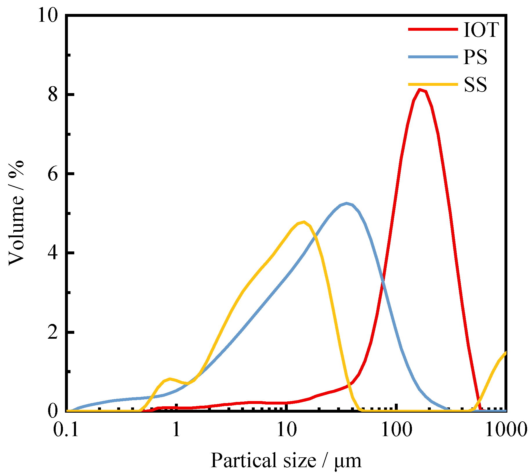
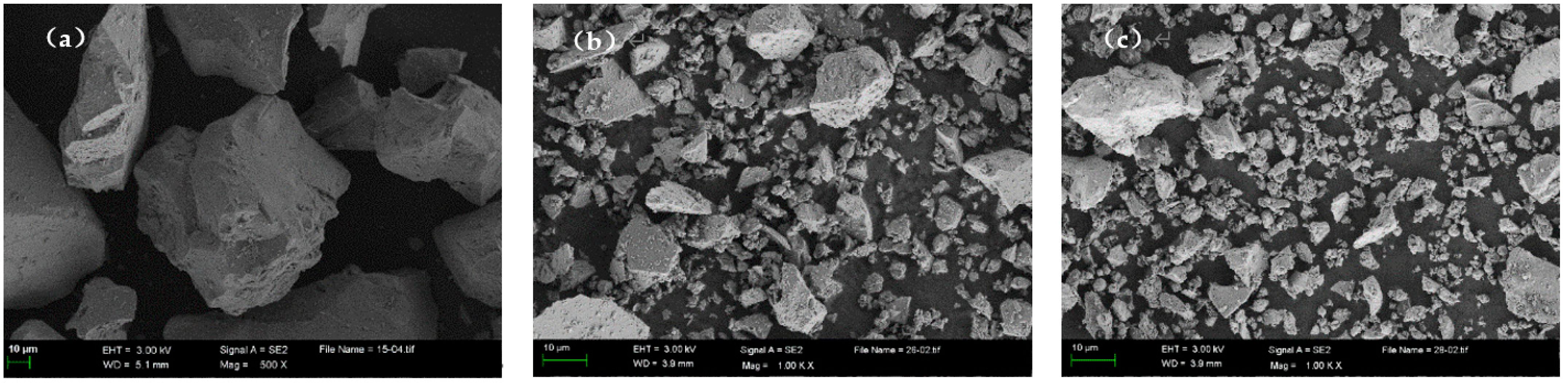
2.1. Raw Materials
2.2. Experimental Methods
2.2.1. Grinding
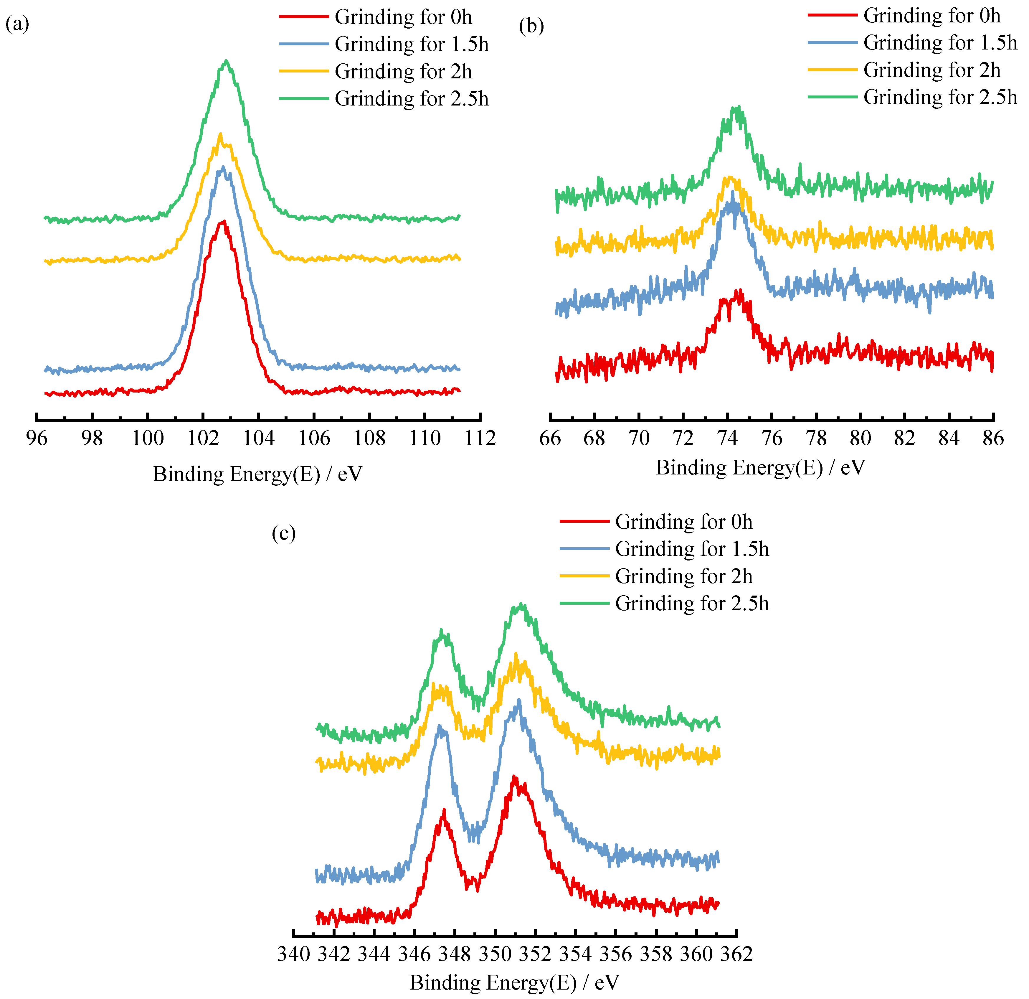
2.2.2. X-ray Photoelectron Spectroscopy
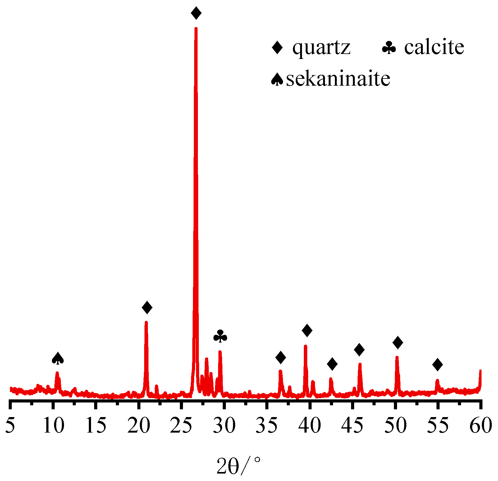
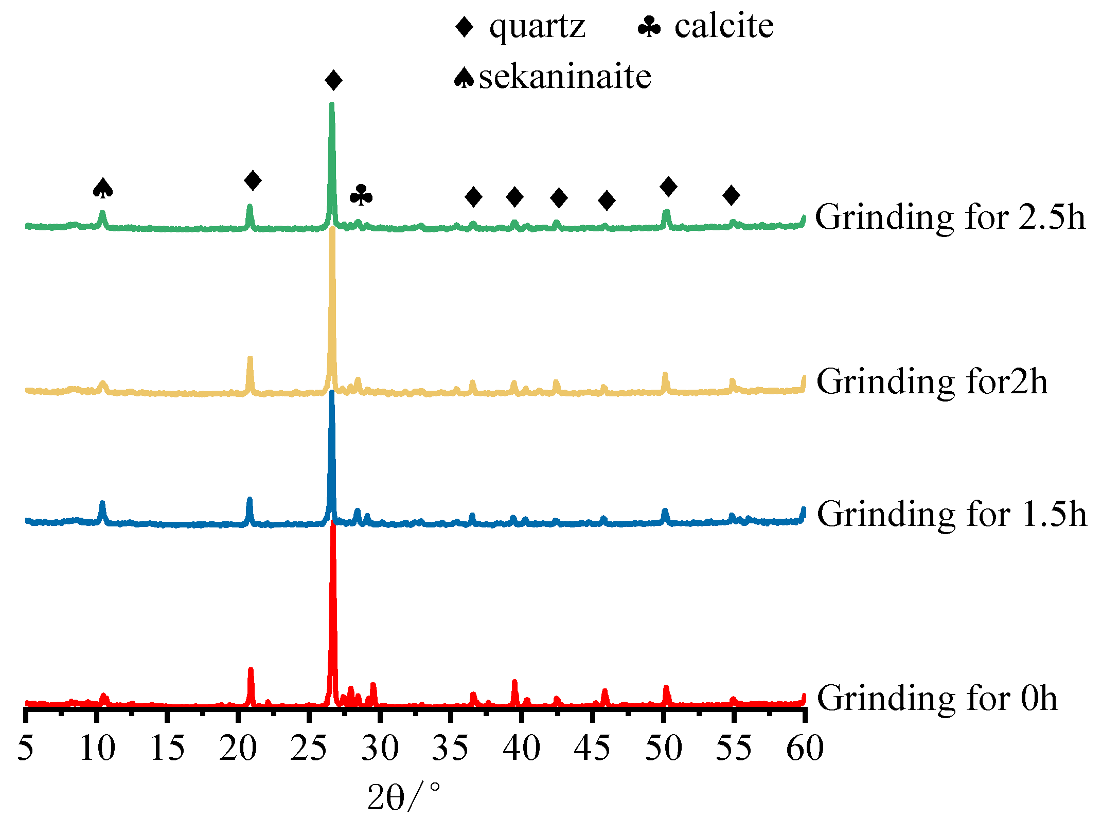
2.2.3. X-ray Diffractometer
2.2.4. Preparation of Specimens
2.2.5. Compressive Strength
2.2.6. Mercury Intrusion Porosimetry
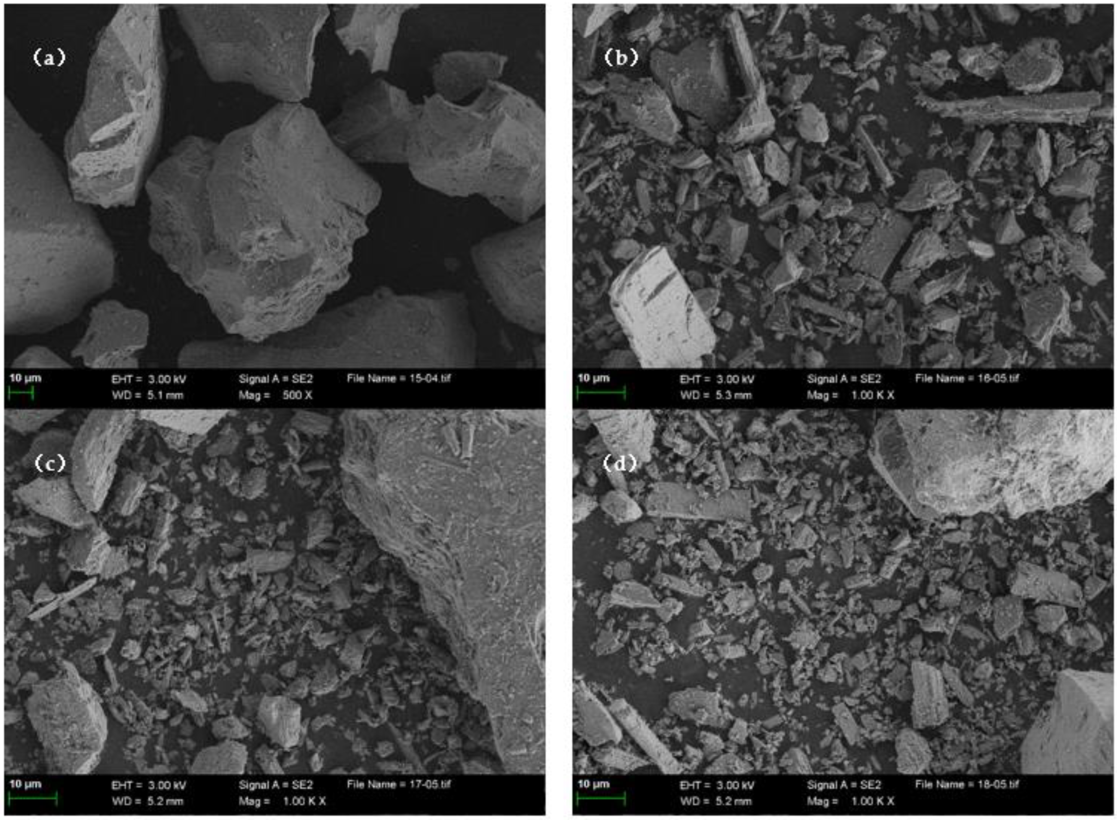
2.2.7. Backscattering Electron Tests and Energy Dispersive Spectrometer
3. Results and Discussion
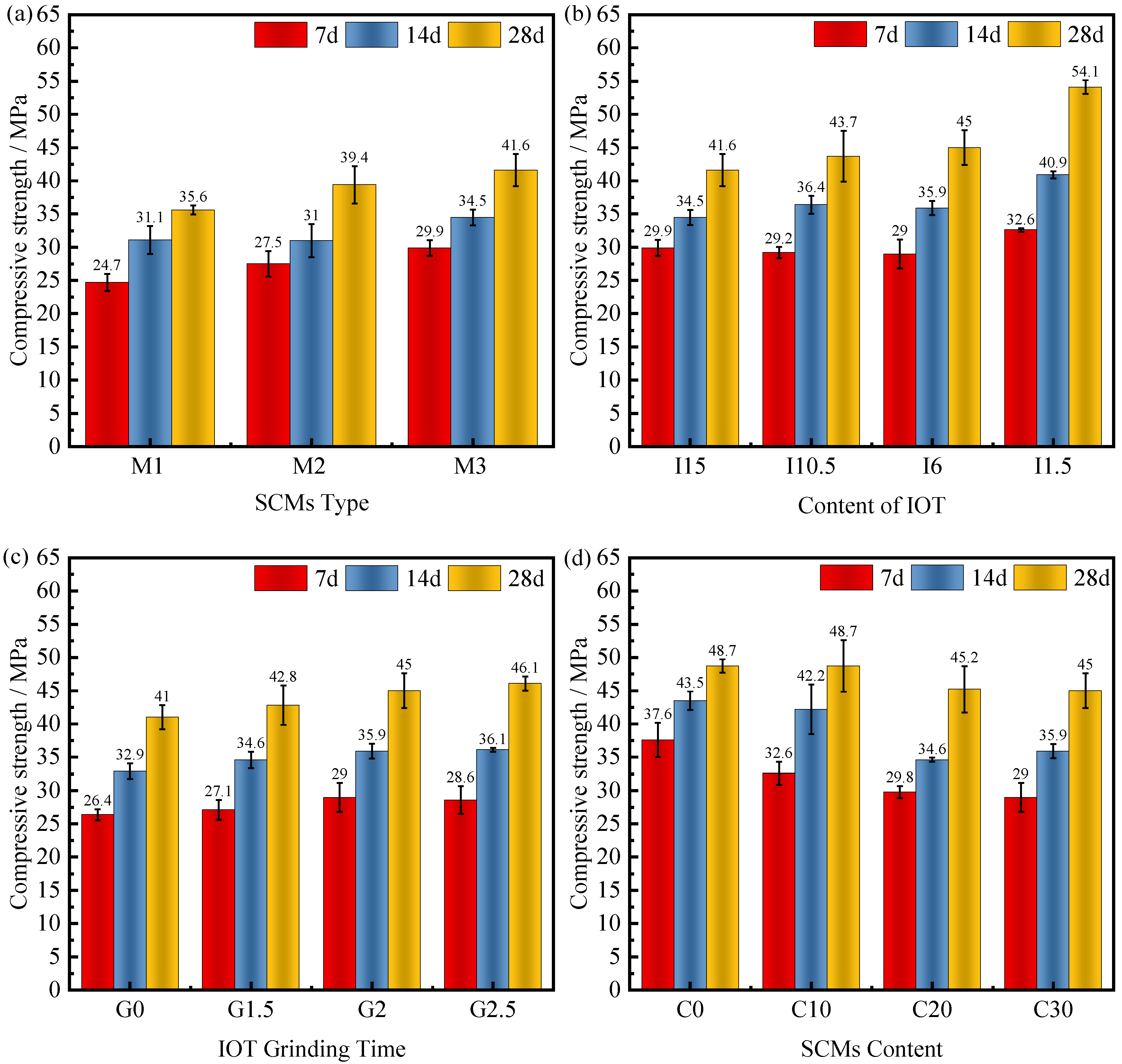
3.1. Compressive Strength
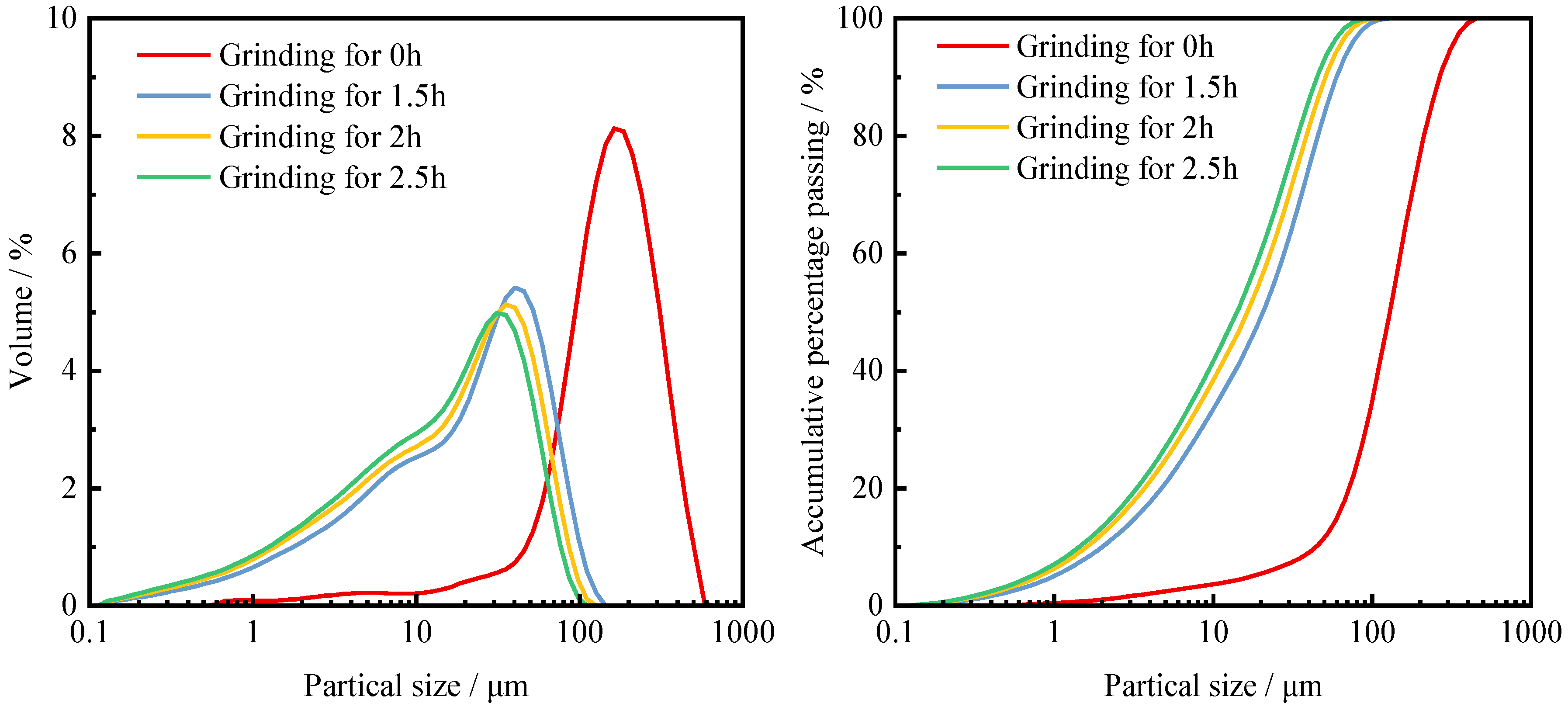
3.2. Mechanical Activation of IOT
3.3. Pore Structures
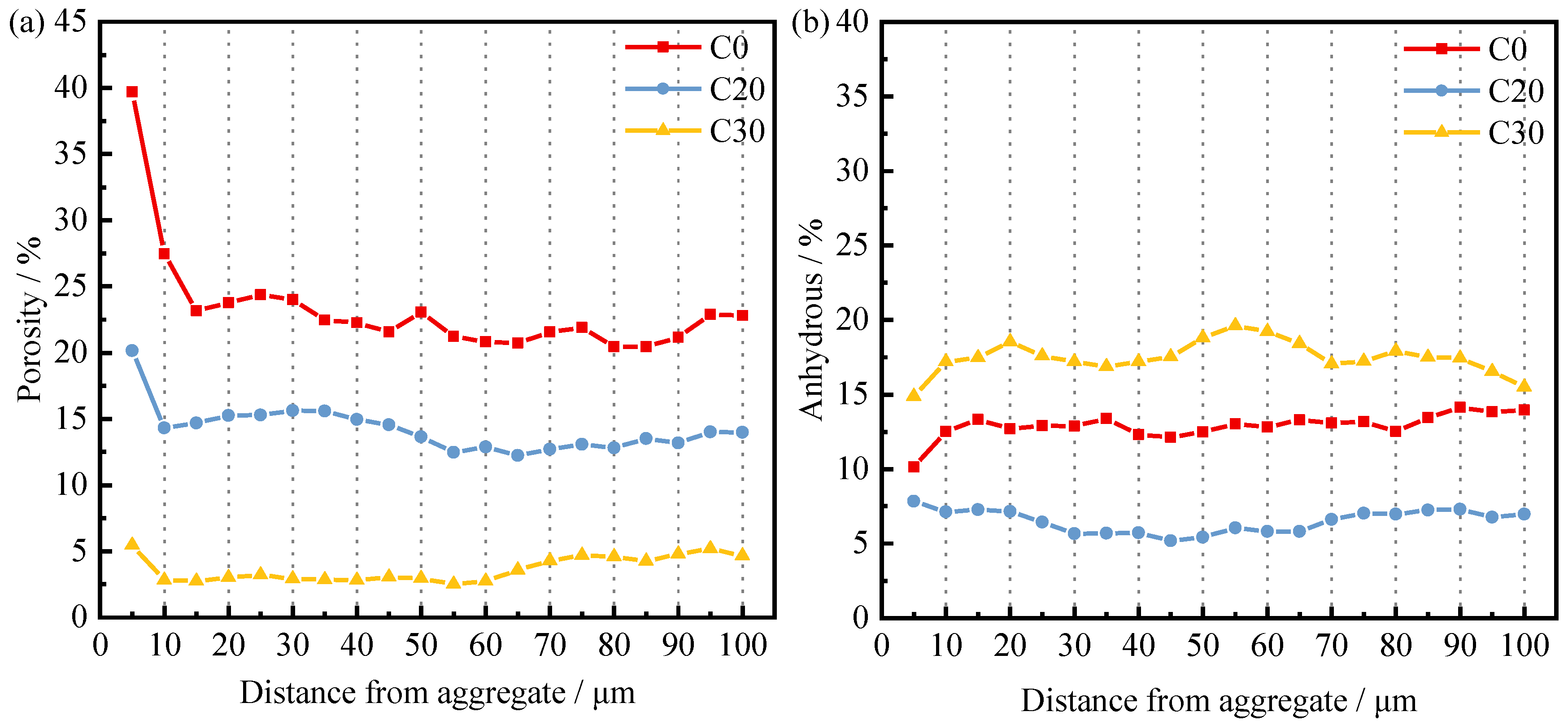
3.4. Interfacial Transition Zone
4. Conclusions
- Compared with using IOTs alone as SCMs, there are significant advantages of using SCMs in the compounding system. PS makes up for the low activity of IOTs, and the synergistic mechanism between SS and PS can further enhance the compressive properties of concrete. Changing the fineness of IOTs can improve the compressive properties of concrete thanks to its increased activity.
- The pores of the ITZ of concrete were optimized after the introduction of composite SCMs. When the dosage is increased by 20% or the grinding time of IOTs is increased, it can reduce the porosity of the ITZ and promote the hydration of the particles within the ITZ, thus reducing the calcium–silica ratio and achieving the purpose of enhancing the ITZ.
- Composite SCMs can deteriorate the matrix pores of the concrete. The increase in pore volume and the coarsening of pore structure are mainly manifested by the increase in the amount of SCMs or the change in the fineness of IOTs. This degradation will be aggravated by the possibility of inducing matrix damage, which will lead to the loss of concrete strength. However, the strength loss due to matrix pore deterioration is within the acceptable range since concrete mostly suffers from interface damage. Therefore, the recommended value of compound SCMs admixture is 20–30%.
- The introduction of composite SCMs makes concrete suffer from a common defect, i.e., lower early strength than normal concrete. The mechanism behind this phenomenon and improvement measures will be the focus of subsequent research.
Author Contributions
Funding
Acknowledgments
Conflicts of Interest
References
- Pan, H.; Zhou, G.; Cheng, Z.; Yang, R.; He, L.; Zeng, D.; Sun, B. Advances in Geochemical Survey of Mine Tailings Project in China. J. Geochem. Explor. 2014, 139, 193–200. [Google Scholar] [CrossRef]
- Zhao, F.-Q.; Zhao, J.; Liu, H.-J. Autoclaved Brick from Low-Silicon Tailings. Constr. Build. Mater. 2009, 23, 538–541. [Google Scholar] [CrossRef]
- China Comprehensive Utilization of Bulk Industrial Solid Waste Industry Development Report (2019–2020). In Industrial Solid Waste Network; Zhongzhuanxinke Environmental Technology Co.: Beijing, China, 2020.
- Yang, C.; Du, G.; Zheng, Q. 2018 China’s Bulk Industrial Solid Waste Comprehensive Utilization Industry Developmentreport; Solid and Hazardous Waste Management Professional Committee of China Environmental Protection Federation: Beijing, China, 2018. [Google Scholar]
- Rao, G.V.; Markandeya, R.; Sharma, S.K. Recovery of Iron Values from Iron Ore Slimes of Donimalai Tailing Dam. Trans. Indian Inst. Met. 2016, 69, 143–150. [Google Scholar] [CrossRef]
- Chen, Q.-S.; Zhang, Q.-L.; Fourie, A.; Chen, X.; Qi, C.-C. Experimental Investigation on the Strength Characteristics of Cement Paste Backfill in a Similar Stope Model and Its Mechanism. Constr. Build. Mater. 2017, 154, 34–43. [Google Scholar] [CrossRef]
- Qi, C.; Fourie, A. Cemented Paste Backfill for Mineral Tailings Management: Review and Future Perspectives. Miner. Eng. 2019, 144, 106025. [Google Scholar] [CrossRef]
- Huang, X.; Ranade, R.; Ni, W.; Li, V.C. Development of Green Engineered Cementitious Composites Using Iron Ore Tailings as Aggregates. Constr. Build. Mater. 2013, 44, 757–764. [Google Scholar] [CrossRef]
- Lv, X.; Shen, W.; Wang, L.; Dong, Y.; Zhang, J.; Xie, Z. A Comparative Study on the Practical Utilization of Iron Tailings as a Complete Replacement of Normal Aggregates in Dam Concrete with Different Gradation. J. Clean. Prod. 2019, 211, 704–715. [Google Scholar] [CrossRef]
- Mendes, B.C.; Pedroti, L.G.; Fontes, M.P.F.; Ribeiro, J.C.L.; Vieira, C.M.F.; Pacheco, A.A.; de Azevedo, A.R.G. Technical and Environmental Assessment of the Incorporation of Iron Ore Tailings in Construction Clay Bricks. Constr. Build. Mater. 2019, 227, 116669. [Google Scholar] [CrossRef]
- Luo, L.; Li, K.; Fu, W.; Liu, C.; Yang, S. Preparation, Characteristics and Mechanisms of the Composite Sintered Bricks Produced from Shale, Sewage Sludge, Coal Gangue Powder and Iron Ore Tailings. Constr. Build. Mater. 2020, 232, 117250. [Google Scholar] [CrossRef]
- Luo, L.; Zhang, Y.; Bao, S.; Chen, T. Utilization of Iron Ore Tailings as Raw Material for Portland Cement Clinker Production. Adv. Mater. Sci. Eng. 2016, 2016, 1596047. [Google Scholar] [CrossRef] [Green Version]
- Duan, P.; Yan, C.; Zhou, W.; Ren, D. Fresh Properties, Compressive Strength and Microstructure of Fly Ash Geopolymer Paste Blended with Iron Ore Tailing under Thermal Cycle. Constr. Build. Mater. 2016, 118, 76–88. [Google Scholar] [CrossRef]
- Lothenbach, B.; Scrivener, K.; Hooton, R.D. Supplementary Cementitious Materials. Cem. Concr. Res. 2011, 41, 1244–1256. [Google Scholar] [CrossRef]
- Li, J.; Zhang, W.; Xu, K.; Monteiro, P.J.M. Fibrillar Calcium Silicate Hydrate Seeds from Hydrated Tricalcium Silicate Lower Cement Demand. Cem. Concr. Res. 2020, 137, 106195. [Google Scholar] [CrossRef]
- Ollivier, J.P.; Maso, J.C.; Bourdette, B. Interfacial Transition Zone in Concrete. Adv. Cem. Based Mater. 1995, 2, 30–38. [Google Scholar] [CrossRef]
- Qudoos, A.; Kim, H.G.; Ryou, J.S. Influence of the Surface Roughness of Crushed Natural Aggregates on the Microhardness of the Interfacial Transition Zone of Concrete with Mineral Admixtures and Polymer Latex. Constr. Build. Mater. 2018, 168, 946–957. [Google Scholar] [CrossRef]
- Arribas, I.; Santamaría, A.; Ruiz, E.; Ortega-López, V.; Manso, J. Electric Arc Furnace Slag and Its Use in Hydraulic Concrete. Constr. Build. Mater. 2015, 90, 68–79. [Google Scholar] [CrossRef]
- Juenger, M.C.G.; Winnefeld, F.; Provis, J.L.; Ideker, J.H. Advances in Alternative Cementitious Binders. Cem. Concr. Res. 2011, 41, 1232–1243. [Google Scholar] [CrossRef]
- Zhang, N.; Tang, B.; Liu, X. Cementitious Activity of Iron Ore Tailing and Its Utilization in Cementitious Materials, Bricks and Concrete. Constr. Build. Mater. 2021, 288, 123022. [Google Scholar] [CrossRef]
- Saedi, A.; Jamshidi-Zanjani, A.; Darban, A.K. A Review on Different Methods of Activating Tailings to Improve Their Cementitious Property as Cemented Paste and Reusability. J. Environ. Manag. 2020, 270, 110881. [Google Scholar] [CrossRef]
- Kumar, S.; Kumar, R.; Bandopadhyay, A.; Alex, T.C.; Kumar, B.R.; Das, S.K.; Mehrotra, S.P. Mechanical Activation of Granulated Blast Furnace Slag and Its Effect on the Properties and Structure of Portland Slag Cement. Cem. Concr. Compos. 2008, 30, 679–685. [Google Scholar] [CrossRef]
- Yao, G.; Wang, Q.; Su, Y.; Wang, J.; Qiu, J.; Lyu, X. Mechanical Activation as an Innovative Approach for the Preparation of Pozzolan from Iron Ore Tailings. Miner. Eng. 2020, 145, 106068. [Google Scholar] [CrossRef]
- Wu, C.R.; Hong, Z.Q.; Yin, Y.H.; Kou, S.H. Mechanical Activated Waste Magnetite Tailing as Pozzolanic Material Substitute for Cement in the Preparation of Cement Products. Constr. Build. Mater. 2020, 252, 119129. [Google Scholar] [CrossRef]
- Han, P. Experimental Study on High Silicon Iron Ore Tailings Effect on Concrete Workability and Compressive Strength; Northeastern University: Boston, MA, USA, 2013. [Google Scholar]
- Han, F.; Song, S.; Liu, J.; Huang, S. Properties of Steam-Cured Precast Concrete Containing Iron Tailing Powder. Powder Technol. 2019, 345, 292–299. [Google Scholar] [CrossRef]
- Han, F.; Zhou, Y.; Zhang, Z. Effect of Gypsum on the Properties of Composite Binder Containing High-Volume Slag and Iron Tailing Powder. Constr. Build. Mater. 2020, 252, 119023. [Google Scholar] [CrossRef]
- Allahverdi, A.; Pilehvar, S.; Mahinroosta, M. Influence of Curing Conditions on the Mechanical and Physical Properties of Chemically-Activated Phosphorous Slag Cement. Powder Technol. 2016, 288, 132–139. [Google Scholar] [CrossRef]
- Pang, M.; Sun, Z.; Chen, M.; Lang, J.; Dong, J.; Tian, X.; Sun, J. Influence of Phosphorus Slag on Physical and Mechanical Properties of Cement Mortars. Materials 2020, 13, 2390. [Google Scholar] [CrossRef]
- Dong-Xu, L.; Lin, C.; Zhong-Zi, X.; Zhi-Min, L. A Blended Cement Containing Blast Furnace Slag and Phosphorous Slag. J. Wuhan Univ. Technol. Mater. Sci. Ed. 2002, 17, 62–65. [Google Scholar] [CrossRef]
- Chen, X.; Fang, K.; Yang, H.; Peng, H. Hydration Kinetics of Phosphorus Slag-Cement Paste. J. Wuhan Univ. Technol. Mater. Sci. Ed. 2011, 26, 142–146. [Google Scholar] [CrossRef]
- Gao, P.; Lu, X.; Yang, C.; Li, X.; Shi, N.; Jin, S. Microstructure and Pore Structure of Concrete Mixed with Superfine Phosphorous Slag and Superplasticizer. Constr. Build. Mater. 2008, 22, 837–840. [Google Scholar] [CrossRef]
- Zhang, Z.; Wang, Q.; Yang, J. Hydration Mechanisms of Composite Binders Containing Phosphorus Slag at Different Temperatures. Constr. Build. Mater. 2017, 147, 720–732. [Google Scholar] [CrossRef]
- Li, D.; Shen, J.; Mao, L.; Wu, X. The Influence of Admixtures on the Properties of Phosphorous Slag Cement. Cem. Concr. Res. 2000, 30, 1169–1173. [Google Scholar] [CrossRef]
- Allahverdi, A.; Abadi, M.M.B.R.; Hossain, K.M.A.; Lachemi, M. Resistance of Chemically-Activated High Phosphorous Slag Content Cement against Freeze–Thaw Cycles. Cold Reg. Sci. Technol. 2014, 103, 107–114. [Google Scholar] [CrossRef]
- Zhao, Q.; Wu, Y. The Influence of Steel Slag on Phosphorous Slag Cement. Key Eng. Mater. 2012, 509, 106–112. [Google Scholar] [CrossRef]
- Guo, J.; Bao, Y.; Wang, M. Steel Slag in China: Treatment, Recycling, and Management. Waste Manag. 2018, 78, 318–330. [Google Scholar] [CrossRef] [PubMed]
- Kourounis, S.; Tsivilis, S.; Tsakiridis, P.; Papadimitriou, G.D.; Tsibouki, Z. Properties and Hydration of Blended Cements with Steelmaking Slag. Cem. Concr. Res. 2007, 37, 815–822. [Google Scholar] [CrossRef]
- Tsakiridis, P.E.; Papadimitriou, G.D.; Tsivilis, S.; Koroneos, C. Utilization of Steel Slag for Portland Cement Clinker Production. J. Hazard. Mater. 2008, 152, 805–811. [Google Scholar] [CrossRef]
- GB175-2007; Common Portland Cement. National Standards of People’s Republic of China: Beijing, China, 2007. (In Chinese)
- GB/T 50081-2019; Standard for Test Methods of Concrete Physical and Mechanical Properties. National Standards of People’s Republic of China: Beijing, China, 2019. (In Chinese)
- Peng, Y.; Zhang, J.; Liu, J.; Ke, J.; Wang, F. Properties and Microstructure of Reactive Powder Concrete Having a High Content of Phosphorous Slag Powder and Silica Fume. Constr. Build. Mater. 2015, 101, 482–487. [Google Scholar] [CrossRef]
- Han, F.; Luo, A.; Liu, J.; Zhang, Z. Properties of High-Volume Iron Tailing Powder Concrete under Different Curing Conditions. Constr. Build. Mater. 2020, 241, 118108. [Google Scholar] [CrossRef]
- Huang, Q.; Zhu, X.; Liu, D.; Zhao, L.; Zhao, M. Modification of Water Absorption and Pore Structure of High-Volume Fly Ash Cement Pastes by Incorporating Nanosilica. J. Build. Eng. 2020, 33, 101638. [Google Scholar] [CrossRef]
- Cai, L.; Ma, B.; Li, X.; Lv, Y.; Liu, Z.; Jian, S. Mechanical and Hydration Characteristics of Autoclaved Aerated Concrete (AAC) Containing Iron-Tailings: Effect of Content and Fineness. Constr. Build. Mater. 2016, 128, 361–372. [Google Scholar] [CrossRef]
- Yang, M.; Sun, J.; Dun, C.; Duan, Y.; Meng, Z. Cementitious Activity Optimization Studies of Iron Tailings Powder as a Concrete Admixture. Constr. Build. Mater. 2020, 265, 120760. [Google Scholar] [CrossRef]
- Zhuang, S.; Wang, Q. Inhibition Mechanisms of Steel Slag on the Early-Age Hydration of Cement. Cem. Concr. Res. 2021, 140, 106283. [Google Scholar] [CrossRef]
- Cheng, L.; Sheng, G.; Pi, Y.; Zhu, C. Effect of Retardation Mechanism of Phosphorous Slag on Portland Cement. Bull. Chin. Ceram. Soc. 2005, 24, 40–44. (In Chinese) [Google Scholar]
- Yao, G.; Wang, Q.; Wang, Z.; Wang, J.; Lyu, X. Activation of Hydration Properties of Iron Ore Tailings and Their Application as Supplementary Cementitious Materials in Cement. Powder Technol. 2020, 360, 863–871. [Google Scholar] [CrossRef]
- Zhao, J.; Ni, K.; Su, Y.; Shi, Y. An Evaluation of Iron Ore Tailings Characteristics and Iron Ore Tailings Concrete Properties. Constr. Build. Mater. 2021, 286, 122968. [Google Scholar] [CrossRef]
- Piao, C. Study on the Activation Process and Mechanism of Iron Tailings Powder and Its Influence on the Performance of Concrete. Dissertation Thesis, China University of Mining & Technology, Beijing, China, 2017. (In Chinese). [Google Scholar]
- Yao, G.; Liu, Q.; Wang, J.; Wu, P.; Lyu, X. Effect of Mechanical Grinding on Pozzolanic Activity and Hydration Properties of Siliceous Gold Ore Tailings. J. Clean. Prod. 2019, 217, 12–21. [Google Scholar] [CrossRef]
- Cheng, Y.; Huang, F.; Li, W.; Liu, R.; Li, G.; Wei, J. Test Research on the Effects of Mechanochemically Activated Iron Tailings on the Compressive Strength of Concrete. Constr. Build. Mater. 2016, 118, 164–170. [Google Scholar] [CrossRef]
- Ke, X.; Zhou, X.; Wang, X.; Wang, T.; Hou, H.; Zhou, M. Effect of Tailings Fineness on the Pore Structure Development of Cemented Paste Backfill. Constr. Build. Mater. 2016, 126, 345–350. [Google Scholar] [CrossRef]
- Xie, Y.; Corr, D.J.; Jin, F.; Zhou, H.; Shah, S.P. Experimental Study of the Interfacial Transition Zone (ITZ) of Model Rock-Filled Concrete (RFC). Cem. Concr. Compos. 2015, 55, 223–231. [Google Scholar] [CrossRef]
- Djerbi, A. Effect of Recycled Coarse Aggregate on the New Interfacial Transition Zone Concrete. Constr. Build. Mater. 2018, 190, 1023–1033. [Google Scholar] [CrossRef]
- Wu, K.; Han, H.; Li, H.; Dong, B.; Liu, T.; De Schutter, G. Experimental Study on Concurrent Factors Influencing the ITZ Effect on Mass Transport in Concrete. Cem. Concr. Compos. 2021, 123, 104215. [Google Scholar] [CrossRef]
- Erdem, S.; Dawson, A.R.; Thom, N.H. Influence of the Micro-and Nanoscale Local Mechanical Properties of the Interfacial Transition Zone on Impact Behavior of Concrete Made with Different Aggregates. Cem. Concr. Res. 2012, 42, 447–458. [Google Scholar] [CrossRef]
- Chen, W.; Brouwers, H.J.H. The Hydration of Slag, Part 1: Reaction Models for Alkali-Activated Slag. J. Mater. Sci. 2007, 42, 428–443. [Google Scholar] [CrossRef]


| Composition | SiO2 | Fe2O3 | CaO | MgO | Al2O3 | K2O | Na2O | P2O5 |
|---|---|---|---|---|---|---|---|---|
| IOT | 62.26 | 14.37 | 7.78 | 6.33 | 4.78 | 1.40 | 1.34 | — |
| PS | 39.08 | 1.14 | 47.45 | 2.90 | 3.94 | 0.87 | 0.60 | 2.34 |
| SS | 15.2 | 27.54 | 42.65 | 6.05 | 2.53 | 0.06 | 0.02 | 1.97 |
| Cement | 22.50 | 3.43 | 66.30 | 0.83 | 4.86 | 0.43 | 0.22 | — |
| Samples | Cement | Water | SCMs | IOTs-FA | IOTs-CA | WR | IOT Grinding Time | ||
|---|---|---|---|---|---|---|---|---|---|
| IOT | PS | SS | |||||||
| M1 | 294 | 185 | 126 | 0 | 0 | 740 | 1110 | 4.5 | 2 h |
| M2 | 294 | 185 | 63 | 63 | 0 | 740 | 1110 | 4.5 | 2 h |
| M3 | 294 | 185 | 63 | 32 | 32 | 740 | 1110 | 4.5 | 2 h |
| I15 | 294 | 185 | 63 | 32 | 32 | 740 | 1110 | 4.5 | 2 h |
| I10.5 | 294 | 185 | 44 | 41 | 41 | 740 | 1110 | 4.5 | 2 h |
| I6 | 294 | 185 | 25 | 50 | 50 | 740 | 1110 | 4.5 | 2 h |
| I1.5 | 294 | 185 | 6 | 60 | 60 | 740 | 1110 | 4.5 | 2 h |
| G0 | 294 | 185 | 25 | 50 | 50 | 740 | 1110 | 4.5 | 0 h |
| G1.5 | 294 | 185 | 25 | 50 | 50 | 740 | 1110 | 4.5 | 1.5 h |
| G2 | 294 | 185 | 25 | 50 | 50 | 740 | 1110 | 4.5 | 2 h |
| G2.5 | 294 | 185 | 25 | 50 | 50 | 740 | 1110 | 4.5 | 2.5 h |
| C0 | 420 | 185 | 0 | 0 | 0 | 740 | 1110 | 4.5 | 0 |
| C10 | 378 | 185 | 8.5 | 17 | 17 | 740 | 1110 | 4.5 | 2 h |
| C20 | 336 | 185 | 17 | 34 | 34 | 740 | 1110 | 4.5 | 2 h |
| C30 | 294 | 185 | 25 | 50 | 50 | 740 | 1110 | 4.5 | 2 h |
| Grinding Time/h | 0 | 1.5 | 2 | 2.5 |
|---|---|---|---|---|
| Specific surface area/m2·kg−1 | 646 | 1290 | 1587 | 1311 |
| G0 | G1.5 | G2/C30 | C0 | C20 | |
|---|---|---|---|---|---|
| Ca/Si | 1.76 | 1.74 | 1.14 | 1.81 | 1.42 |
Publisher’s Note: MDPI stays neutral with regard to jurisdictional claims in published maps and institutional affiliations. |
© 2022 by the authors. Licensee MDPI, Basel, Switzerland. This article is an open access article distributed under the terms and conditions of the Creative Commons Attribution (CC BY) license (https://creativecommons.org/licenses/by/4.0/).
Share and Cite
Zhang, Y.; Yang, D.; Gu, X.; Chen, H.; Li, Z. Application of Iron Tailings-Based Composite Supplementary Cementitious Materials (SCMs) in Green Concrete. Materials 2022, 15, 3866. https://doi.org/10.3390/ma15113866
Zhang Y, Yang D, Gu X, Chen H, Li Z. Application of Iron Tailings-Based Composite Supplementary Cementitious Materials (SCMs) in Green Concrete. Materials. 2022; 15(11):3866. https://doi.org/10.3390/ma15113866
Chicago/Turabian StyleZhang, Yannian, Daokui Yang, Xiaowei Gu, Hao Chen, and Zhijun Li. 2022. "Application of Iron Tailings-Based Composite Supplementary Cementitious Materials (SCMs) in Green Concrete" Materials 15, no. 11: 3866. https://doi.org/10.3390/ma15113866