
Improved Equations for the Torsional Strength of Reinforced Concrete Beams for Codes of Practice Based on the Space Truss Analogy


Abstract
:1. Introduction
2. Equations from the Reference Design Codes
- The limit of the wall’s thickness of the equivalent hollow beam, which determines and limits the area enclosed within the flow of shear stress acting on the beam’s cross-section;
- The flow of shear stress, which is induced by the external torque, and the corresponding shear resultant forces in each wall;
- The criteria to compute the torsional strength, which, depending on the underlying mechanical model and design code, consider separately the strength contributed by the torsional tensile reinforcement and the strength contributed by the compressive concrete;
- The maximum limit allowed for the compressive stress in the concrete struts to avoid a brittle failure of the beam due to concrete crushing;
- The angle of the concrete struts to the longitudinal axis of the beam.
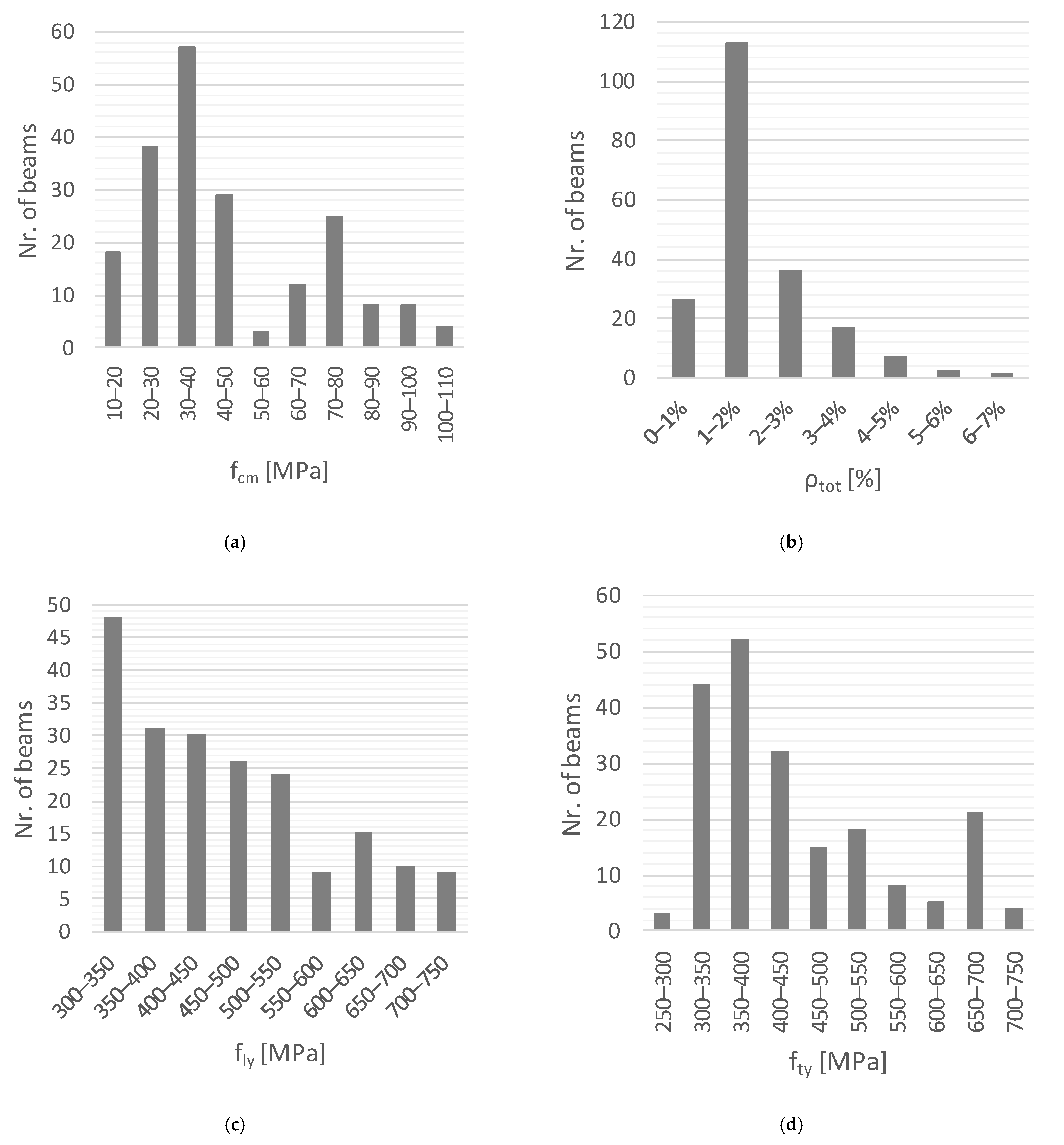
3. Database with Reference Beams
- The main properties of the tested RC beams needed to compute the normative torsional strength should be given;
- The experimental torsional strength should be given and the RC beams should have failed in pure torsion in their ultimate stage as expected;
- The beams should comply with reinforcement requirements from ACI 318R-19 [3]. For instance, and among other requirements, the spacing of the hoops should be less than the upper limit set by the code to avoid untypical behavior (for instance, premature failure) during testing. ACI 318R-19 [3] was the chosen code because it was found to be the one that incorporates a higher number of specific detailing rules for RC beams under torsion.
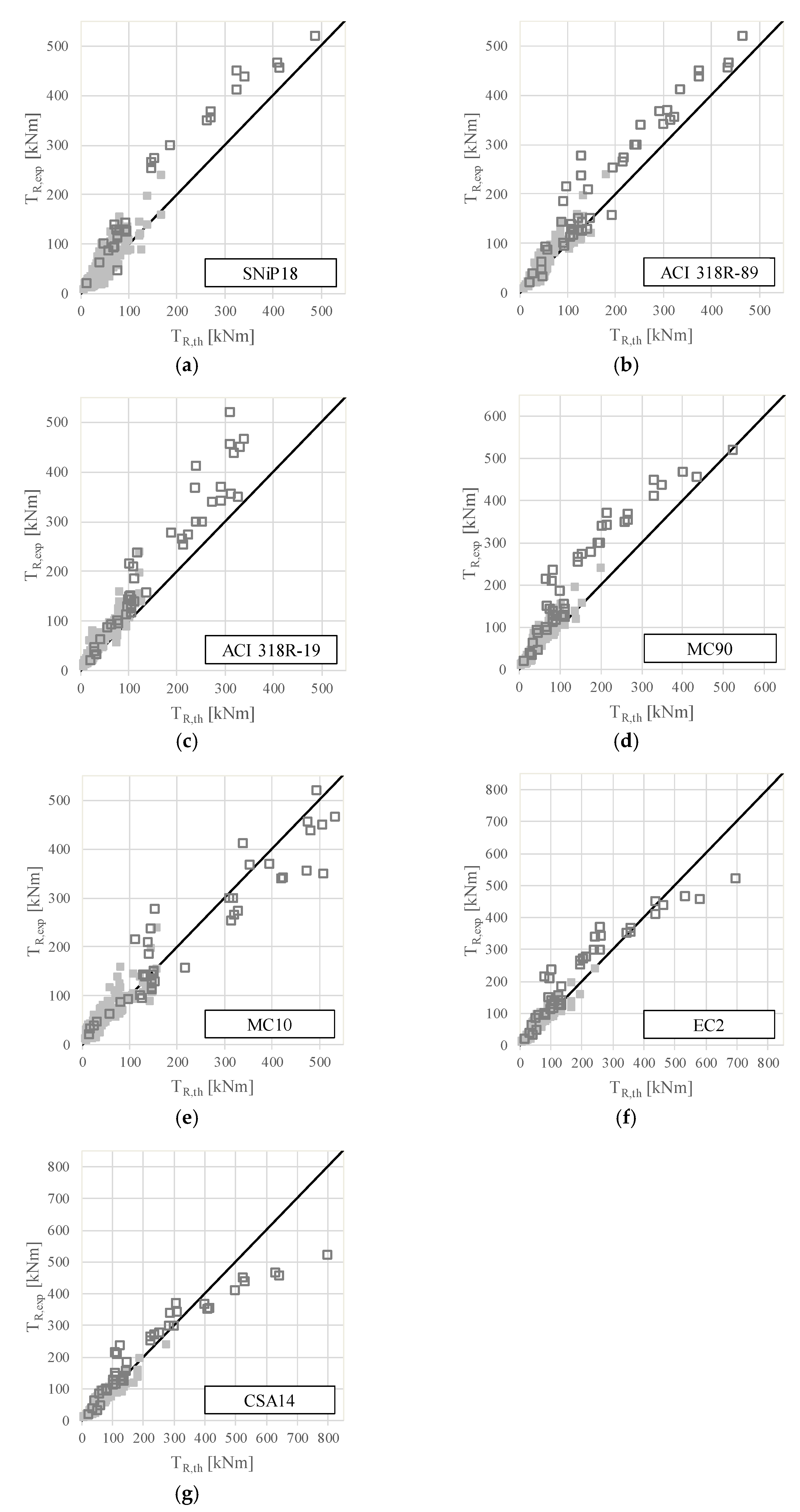
4. Evaluation of Design Codes
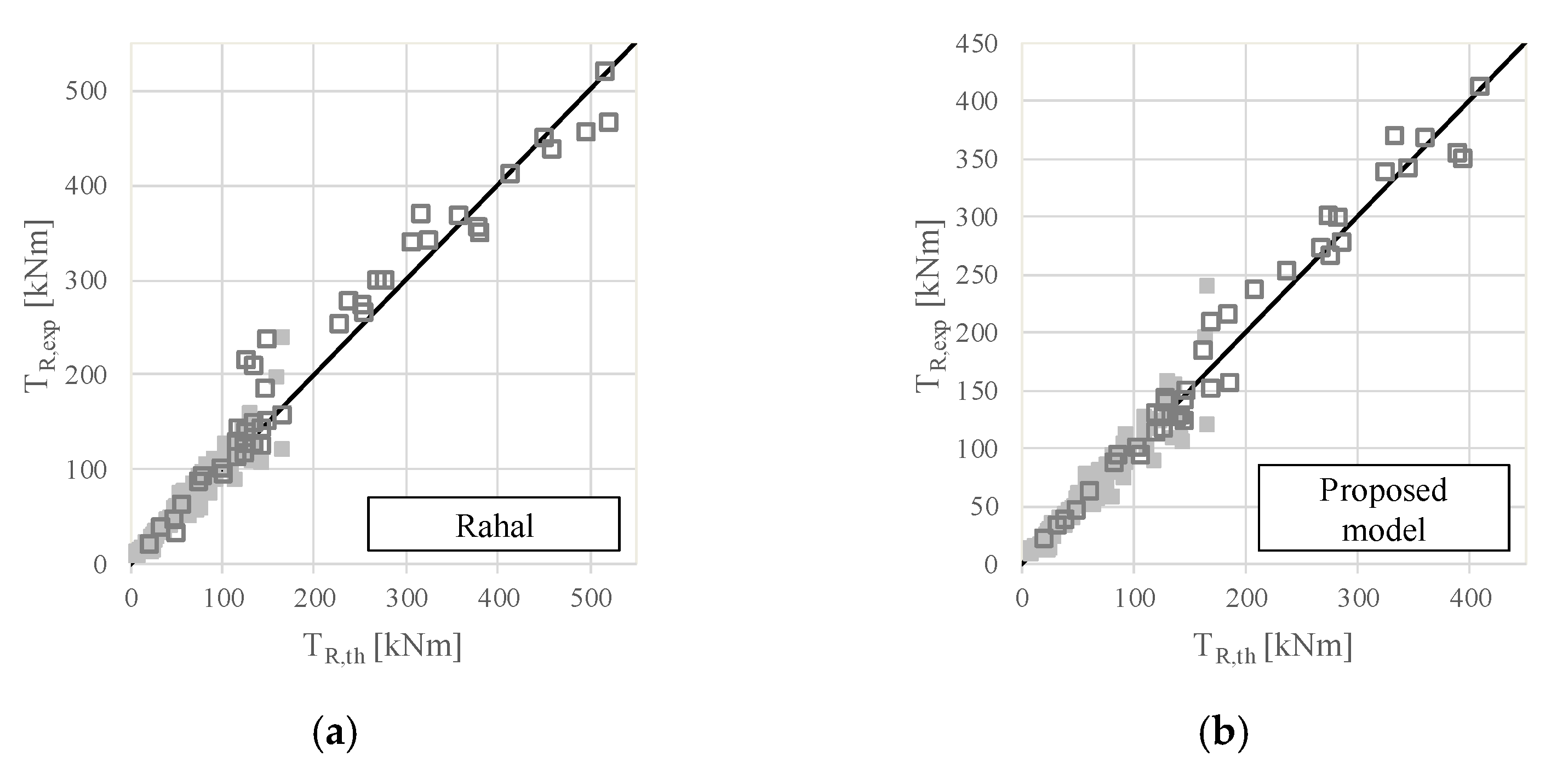
5. Equations Proposed by Rahal
- In the hollow tube model used in the space truss analogy, the shear flow is constant around the perimeter of the tube walls. Design code formulations consider a constant effective thickness for all the walls. As a consequence, the model assumes the same shear stress and shear. As pointed out by Rahal [8], this is not consistent with the experimental results on RC rectangular beams under torsion that show different conditions on the different faces of the cross-section [10,12,37]. Experiments show that larger tensile strains are observed in the longer legs of the hoops and larger diagonal strains are observed in the longer faces of the cross-section. In this regard and based on these observations, a refined variable-angle space truss model incorporating different strut inclination angles in the different faces of the cross-section was recently proposed by De Domenico [50];
- In addition, Rahal [8] also noted that in most experiments [17,40,51], the concrete of the beams did not spall at the maximum torque or was limited to the corners of the cross-section [37,42]. However, in Equation (1), the torsional strength is related to the spalled concrete dimensions through area (area enclosed within the shear flow path).
6. Alternative Improvement of the Equations from Rahal
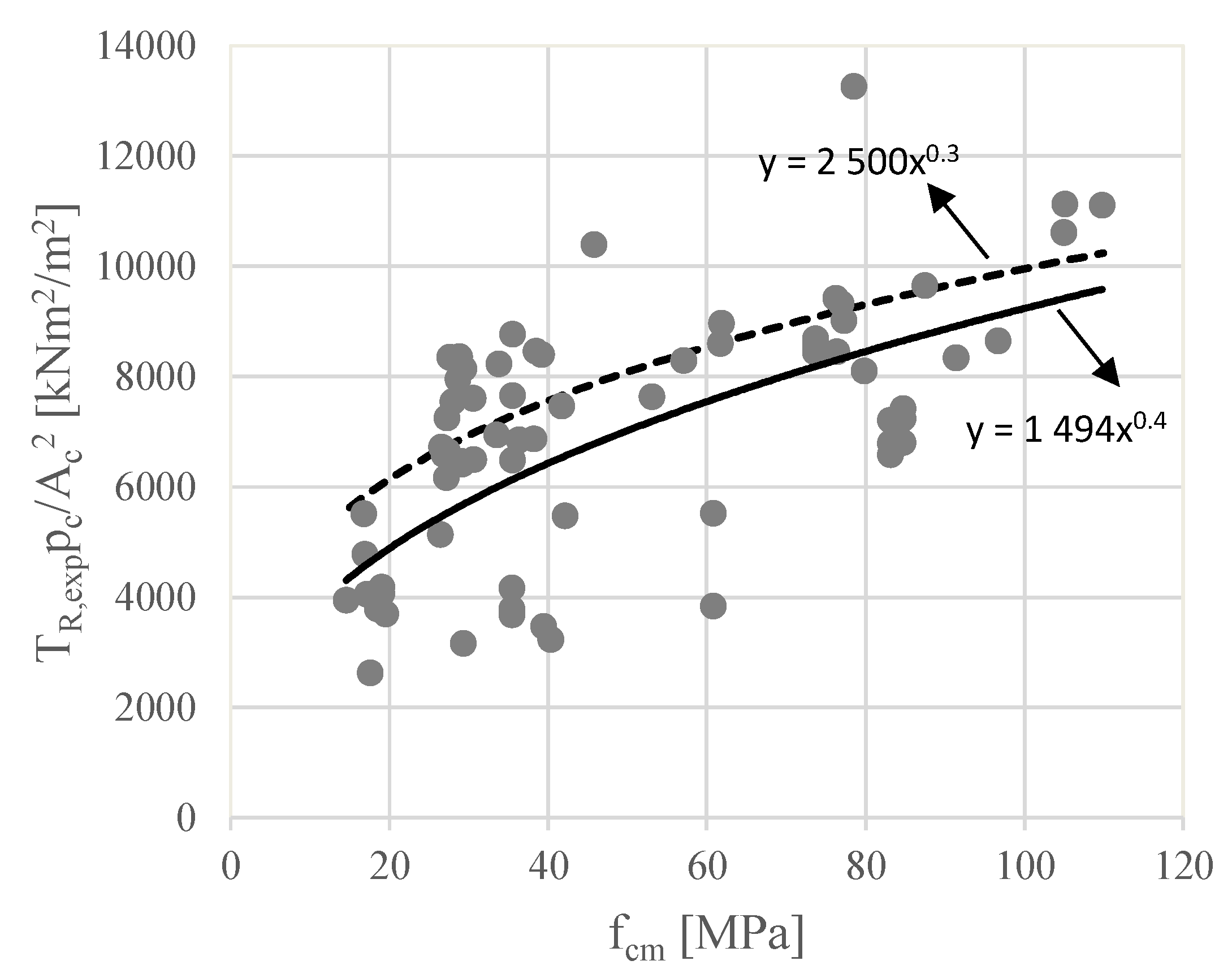
6.1. Upper Limit to Control Concrete Crushing (Over-Reinforced Beams)

6.2. Reinforcement, Concrete Strength, and Concrete Area Terms (Under-Reinforced Beams)
6.3. Proposed Equations
7. Conclusions
- In general, equations from the studied reference codes still need improvements to increase the accuracy and reduce the observed statistical dispersion;
- Some reference design codes overestimate the torsional strength of several reference RC beams from the database noticeably, which is not acceptable for design and justifies further improvements;
- The proposed equations to compute the torsional strength of RC beams showed to be much more reliable and accurate in comparison with code’s equations;
- The proposed equations are simple and can easily be used for practice to assess with accuracy the torsional strength of RC members, including plain and hollow beams, normal- and high-strength concrete beams, as well as under- and over-reinforced beams;
- When compared with similar equations from a previous study [8], the proposed equations were shown to be slightly better at predicting torsional strength;
- This study confirms that simple and reliable design equations can be obtained by simply fitting the results with experimental data existing in the literature and related to the torsional strength of the RC beams.
Author Contributions
Funding
Institutional Review Board Statement
Informed Consent Statement
Data Availability Statement
Conflicts of Interest
Nomenclature
| area enclosed within the outer perimeter of the cross-section | perimeter of the area | ||
| area within the centerline of wall’s thickness (assumed to coincide with the shear flow path) | alied shear force | ||
| total area of longitudinal reinforcement | resistance shear force | ||
| area of bottom longitudinal reinforcement | shear force due to the compressive stresses resisted by concrete | ||
| area of tensile longitudinal steel near the vertical face | shear force due to the axial stresses resisted by the longitudinal reinforcement | ||
| area enclosed within circular shear flow | maximum resistance shear force | ||
| area enclosed within centerline of hoops | shear force due to shear stresses resisted by the transverse reinforcement | ||
| area for one bar of the hoop | smaller dimension of the cross-section | ||
| average compressive strength of concrete | smaller dimension of hoops | ||
| characteristic value of the compressive strength of concrete at 28 days | larger dimension of the cross-section | ||
| average yield strength of longitudinal reinforcement | larger dimension of hoops | ||
| average yield strength of tranerse reinforcement | length of wall i, equal to the distance between the centerline intersection of adjacent walls | ||
| concrete reduction factor | angle of the hoops to the longitudinal axis | ||
| gross perimeter of the cross-section | coefficient to account for the stress state of the compressed chord | ||
| perimeter of the centerline of hoop | efficiency coefficient | ||
| shear stress flow due to torsion | partial safety factor for concrete properties | ||
| longitudinal spacing between hoops | δ | numerical coefficient to account for imperfections | |
| applied torsional moment | angle of the diagonal compressive stresses in concrete struts to the longitudinal axis | ||
| Wall’s thickness of the equivalent hollow section | ν | strength reduction factor for cracked concrete | |
| torsional moment resisted by concrete | ratio of longitudinal reinforcement: | ||
| maximum torsional mome | ratio of transverse reinforcement: | ||
| torsional moment resistance | shear stress due to torsion | ||
| experimental torsional moment resistance | ϕ | reduction coefficient | |
| theoretical torsional moment resistance | concrete resistance factor | ||
| torsional moment resisted by the reinforcement | reinforcement resistance factor | ||
| ultimate torsional moment |
Appendix A

| SinNiP 2018 | ACI 318R-89 | |
|---|---|---|
| Limit of the section wall thickness | Not available | Wall thickness of the hollow section: the section is considered as a plain section; the section is considered as an equivalent plain section. |
| Shear stresses and shear forces due to torsion | Not available | Not available |
| Safety condition | Condition: where | Condition: where For plain section: For hollow section: where |
| Maximum limit by the tension in concrete struts | Maximum limit: y | Maximum limit: , then , then |
| * | Not available | Not available |
| ACI 318R-19 | MC 90 | |
| Limit of the section wall thickness | Wall thickness of the hollow section: If the section is considered as a plain section; If the section is considered as an equivalent plain section. | Wall thickness of the hollow section: If the section is considered as a hollow section; If the section is considered as a plain section (equivalent hollow section).Wall thickness of the plain section (equivalent hollow section): and 2x distance between the face of the section and the axis of the longitudinal reinforcement. |
| Shear stresses and shear forces due to torsion | Shear flow for a thin-walled tube: Shear stress along the perimeter of the section: with | Shear flow at a wall : Shear stress at a wall : where , with . |
| Safety condition | Condition: where (for the present study). | Condition: (a) Shear force due to the force on the longitudinal reinforcement: (c) Shear force due to the force on the transverse reinforcement: |
| Maximum limit by the tension in concrete struts | Maximum limit to plain section: Maximum limit to hollow section: where (for the present study). | Maximum limit: Shear force due to the force on the concrete struts: where |
| * | ||
| * Angle between the concrete struts and the longitudinal axis of the beams. | ||
| MC 10 | Eurocode 2 | |
| Limit of the section wall thickness | Wall thickness of the hollow section: Wall thickness of the plain section (equivalent hollow section): 2x distance between the face of the section and the axis of the longitudinal reinforcement and . | Wall thickness of the hollow section: If the section is considered as a hollow section; If the section is considered as a plain section (equivalent hollow section).Wall thickness of the plain section (equivalent hollow section): e 2x distance between the face of the section and the axis of the longitudinal reinforcement. |
| Shear stresses and shear forces due to torsion | Shear stress at a wall : | Shear flow at a wall : Shear stress at a wall : |
| Safety condition | Condition: Approximation level II: | Condition: |
| Maximum limit by the tension in concrete struts | Maximum limit: Approximation level II: and | Maximum limit: where and , for non-prestressed beams. |
| * | ||
| * Angle between the concrete struts and the longitudinal axis of the beams. | ||
| CSA A23.3-14 | |
| Limit of the section wall thickness | Wall thickness of the hollow section: If the section is considered as a plain section; If the section is considered as an equivalent plains section. |
| Shear stresses and shear forces due to torsion | Not available |
| Safety condition | Condition: where with and (for the present study). |
| Maximum limit by the tension in concrete struts | Maximum limit to plain section: Maximum limit to hollow section: where (for the present study). |
| * | |
| * Angle between the concrete struts and the longitudinal axis of the beams. | |
| Ref. | Beam | ** | ||||||||||||
|---|---|---|---|---|---|---|---|---|---|---|---|---|---|---|
| (m) | (m) | (m) | (m) | (m) | (cm2) | (cm2) | (cm2) | (cm2/m) | (MPa) | (MPa) | (MPa) | |||
| Hsu (1968) | B1 | P | 0.254 | 0.381 | - | 0.216 | 0.343 | 2.53 | 2.53 | 5.07 | 4.68 | 27.6 | 314.0 | 341.0 |
| B3 | P | 0.254 | 0.381 | - | 0.216 | 0.343 | 5.73 | 5.73 | 11.36 | 10.16 | 28.1 | 327.6 | 320.0 | |
| B4 | P | 0.254 | 0.381 | - | 0.216 | 0.343 | 7.74 | 7.74 | 15.48 | 14.01 | 29.2 | 320.0 | 323.4 | |
| B5 | P | 0.254 | 0.381 | - | 0.216 | 0.343 | 10.20 | 10.20 | 20.39 | 18.47 | 30.6 | 332.4 | 321.4 | |
| B6 | P | 0.254 | 0.381 | - | 0.216 | 0.343 | 12.90 | 12.90 | 25.81 | 22.58 | 28.8 | 331.7 | 322.8 | |
| B7 | P | 0.254 | 0.381 | - | 0.216 | 0.343 | 2.53 | 2.53 | 5.16 | 10.16 | 26.0 | 320.0 | 318.6 | |
| B8 | P | 0.254 | 0.381 | - | 0.216 | 0.343 | 2.53 | 2.53 | 5.16 | 22.58 | 26.8 | 322.1 | 320.0 | |
| B9 | P | 0.254 | 0.381 | - | 0.216 | 0.343 | 5.73 | 5.73 | 11.36 | 4.66 | 28.8 | 319.3 | 342.8 | |
| B10 | P | 0.254 | 0.381 | - | 0.216 | 0.343 | 12.90 | 12.90 | 25.8 | 4.66 | 26.5 | 334.0 | 342.0 | |
| C2 | P | 0.254 | 0.254 | - | 0.216 | 0.216 | 2.53 | 2.53 | 5.07 | 6.07 | 26.5 | 334.0 | 345.0 | |
| C4 | P | 0.254 | 0.254 | - | 0.216 | 0.216 | 5.73 | 5.73 | 11.36 | 13.11 | 27.2 | 336.6 | 327.6 | |
| C5 | P | 0.254 | 0.254 | - | 0.216 | 0.216 | 7.74 | 7.74 | 15.48 | 17.67 | 27.2 | 328.3 | 329.0 | |
| C6 | P | 0.254 | 0.254 | - | 0.216 | 0.216 | 10.20 | 10.20 | 20.39 | 23.91 | 27.6 | 315.9 | 327.6 | |
| G2 | P | 0.254 | 0.508 | - | 0.216 | 0.470 | 3.97 | 3.97 | 7.94 | 5.91 | 30.9 | 323.0 | 334.0 | |
| G3 | P | 0.254 | 0.508 | - | 0.216 | 0.470 | 5.73 | 5.73 | 11.36 | 8.29 | 26.8 | 338.6 | 327.6 | |
| G4 | P | 0.254 | 0.508 | - | 0.216 | 0.470 | 7.74 | 7.74 | 15.48 | 11.29 | 28.3 | 325.5 | 321.4 | |
| G5 | P | 0.254 | 0.508 | - | 0.216 | 0.470 | 10.20 | 10.20 | 20.39 | 15.05 | 26.9 | 331.0 | 327.6 | |
| G6 | P | 0.254 | 0.508 | - | 0.216 | 0.470 | 2.53 | 3.80 | 7.60 | 5.61 | 29.9 | 334.0 | 350.0 | |
| G7 | P | 0.254 | 0.508 | - | 0.216 | 0.470 | 3.97 | 5.96 | 12.00 | 8.84 | 31.0 | 319.3 | 322.8 | |
| G8 | P | 0.254 | 0.508 | - | 0.216 | 0.470 | 5.73 | 8.60 | 17.03 | 12.32 | 28.3 | 322.1 | 329.0 | |
| I2 | P | 0.254 | 0.381 | - | 0.216 | 0.343 | 3.97 | 3.97 | 7.94 | 7.25 | 45.2 | 325 | 349 | |
| I3 | P | 0.254 | 0.381 | - | 0.216 | 0.343 | 5.73 | 5.73 | 11.36 | 10.16 | 44.8 | 343.4 | 333.8 | |
| I4 | P | 0.254 | 0.381 | - | 0.216 | 0.343 | 7.74 | 7.74 | 15.48 | 14.01 | 45.0 | 315.2 | 326.2 | |
| I5 | P | 0.254 | 0.381 | - | 0.216 | 0.343 | 10.20 | 10.20 | 20.39 | 18.47 | 45.0 | 310.3 | 325.5 | |
| I6 | P | 0.254 | 0.381 | - | 0.216 | 0.343 | 12.90 | 12.90 | 25.81 | 22.58 | 45.8 | 325.5 | 329.0 | |
| J1 | P | 0.254 | 0.381 | - | 0.216 | 0.343 | 2.53 | 2.53 | 5.16 | 4.66 | 14.3 | 327.6 | 346.2 | |
| J2 | P | 0.254 | 0.381 | - | 0.216 | 0.343 | 3.97 | 3.97 | 8.00 | 7.21 | 14.6 | 320.0 | 340.7 | |
| J3 | P | 0.254 | 0.381 | - | 0.216 | 0.343 | 5.73 | 5.73 | 11.36 | 10.16 | 16.9 | 388.6 | 337.2 | |
| J4 | P | 0.254 | 0.381 | - | 0.216 | 0.343 | 7.74 | 7.74 | 15.48 | 14.01 | 16.8 | 324.1 | 331.7 | |
| K2 | P | 0.152 | 0.495 | - | 0.114 | 0.457 | 2.53 | 3.80 | 7.74 | 6.77 | 30.6 | 335.9 | 337.9 | |
| K3 | P | 0.152 | 0.495 | - | 0.114 | 0.457 | 3.97 | 5.96 | 12.00 | 10.42 | 29.0 | 315.9 | 320.7 | |
| K4 | P | 0.152 | 0.495 | - | 0.114 | 0.457 | 5.73 | 8.60 | 17.03 | 15.05 | 28.6 | 344.1 | 340.0 | |
| M1 | P | 0.254 | 0.381 | - | 0.216 | 0.343 | 3.97 | 3.97 | 8.00 | 4.76 | 29.9 | 326.2 | 353.1 | |
| M2 | P | 0.254 | 0.381 | - | 0.216 | 0.343 | 5.73 | 5.73 | 11.36 | 6.77 | 30.6 | 329.0 | 357.2 | |
| M3 | P | 0.254 | 0.381 | - | 0.216 | 0.343 | 7.74 | 7.74 | 15.48 | 9.24 | 26.8 | 322.1 | 326.2 | |
| M4 | P | 0.254 | 0.381 | - | 0.216 | 0.343 | 10.20 | 10.20 | 20.39 | 12.33 | 26.6 | 318.6 | 326.9 | |
| M5 | P | 0.254 | 0.381 | - | 0.216 | 0.343 | 12.90 | 12.90 | 25.81 | 15.63 | 28.0 | 335.2 | 331.0 | |
| M6 | P | 0.254 | 0.381 | - | 0.216 | 0.343 | 10.20 | 15.30 | 30.58 | 15.63 | 29.4 | 317.9 | 340.7 | |
| N1 | P | 0.152 | 0.305 | - | 0.130 | 0.283 | 1.43 | 1.43 | 2.84 | 3.50 | 29.5 | 352.4 | 341.4 | |
| N1a | P | 0.152 | 0.305 | - | 0.130 | 0.283 | 1.43 | 1.43 | 2.84 | 3.50 | 28.7 | 346.2 | 344.8 |
| Ref. | Beam | ** | ||||||||||||
| (m) | (m) | (m) | (m) | (m) | (cm2) | (cm2) | (cm2) | (cm2/m) | (MPa) | (MPa) | (MPa) | |||
| N2 | P | 0.152 | 0.305 | - | 0.130 | 0.283 | 2.53 | 2.53 | 5.16 | 6.35 | 30.4 | 331.0 | 337.9 | |
| N2a | P | 0.152 | 0.305 | - | 0.130 | 0.283 | 2.53 | 2.53 | 1.61 | 6.21 | 28.4 | 333.1 | 360.7 | |
| N3 | P | 0.152 | 0.305 | - | 0.130 | 0.283 | 1.43 | 2.14 | 4.26 | 5.08 | 27.3 | 351.7 | 351.7 | |
| N4 | P | 0.152 | 0.305 | - | 0.130 | 0.283 | 2.53 | 3.25 | 6.58 | 7.98 | 27.3 | 340.9 | 355.9 | |
| [17] | T4 | P | 0.500 | 0.500 | - | 0.454 | 0.454 | 5.65 | 5.65 | 18.10 | 10.28 | 35.3 | 356.7 | 356.7 |
| Leonhardt, Schelling (1974) | VB2 | P | 0.440 | 0.240 | - | 0.420 | 0.220 | 2.63 | 1.46 | 7.01 | 5.84 | 26.4 | 541.4 | 541.4 |
| VB3 | P | 0.440 | 0.240 | - | 0.420 | 0.220 | 2.63 | 1.46 | 7.01 | 5.84 | 39.1 | 541.4 | 541.4 | |
| VB4 | P | 0.440 | 0.240 | - | 0.420 | 0.220 | 2.63 | 1.46 | 7.01 | 5.84 | 49.8 | 541.4 | 541.4 | |
| VM1 | P | 0.294 | 0.160 | - | 0.280 | 0.146 | 1.50 | 1.00 | 3.00 | 3.63 | 39.1 | 442.4 | 568.9 | |
| VM2 | P | 0.440 | 0.240 | - | 0.420 | 0.220 | 3.30 | 2.20 | 6.60 | 5.32 | 36.1 | 431.6 | 436.5 | |
| VM3 | P | 0.587 | 0.320 | - | 0.561 | 0.294 | 6.42 | 4.28 | 12.84 | 7.14 | 40.0 | 461.0 | 442.4 | |
| VQ1 | P | 0.324 | 0.324 | - | 0.304 | 0.304 | 1.15 | 1.15 | 3.46 | 2.88 | 19.0 | 557.1 | 557.1 | |
| VQ3 | P | 0.580 | 0.186 | - | 0.560 | 0.166 | 1.83 | 0.61 | 4.27 | 3.05 | 17.6 | 432.6 | 432.6 | |
| VQ9 | P | 0.806 | 0.140 | - | 0.786 | 0.120 | 2.54 | 0.56 | 5.08 | 2.82 | 19.5 | 441.4 | 441.4 | |
| VS2-VQ2 | P | 0.440 | 0.240 | - | 0.420 | 0.220 | 1.53 | 0.92 | 3.66 | 3.05 | 19.0 | 432.6 | 432.6 | |
| VS3 | P | 0.440 | 0.240 | - | 0.420 | 0.220 | 2.14 | 1.22 | 5.49 | 4.55 | 19.5 | 432.6 | 432.6 | |
| VS4-VQ5 | P | 0.440 | 0.240 | - | 0.420 | 0.220 | 2.75 | 1.53 | 7.32 | 6.10 | 19.0 | 432.6 | 432.6 | |
| VS9 | P | 0.440 | 0.240 | - | 0.420 | 0.220 | 1.16 | 1.16 | 3.48 | 2.90 | 17.6 | 570.9 | 570.9 | |
| VS10-VB1 | P | 0.440 | 0.240 | - | 0.420 | 0.220 | 2.61 | 1.45 | 6.96 | 5.80 | 19.0 | 570.9 | 570.9 | |
| VU1 | P | 0.440 | 0.240 | - | 0.420 | 0.220 | 1.40 | 0.84 | 3.36 | 5.60 | 19.5 | 441.4 | 441.4 | |
| VU2 | P | 0.440 | 0.240 | - | 0.420 | 0.220 | 1.96 | 1.12 | 5.04 | 5.60 | 19.5 | 441.4 | 441.4 | |
| VU3 | P | 0.440 | 0.240 | - | 0.420 | 0.220 | 2.52 | 1.40 | 6.72 | 4.18 | 18.5 | 441.4 | 441.4 | |
| VU4 | P | 0.440 | 0.240 | - | 0.420 | 0.220 | 2.52 | 1.40 | 6.72 | 2.80 | 18.5 | 441.4 | 441.4 | |
| McMullen, Rangan (1978) | A2 | P | 0.254 | 0.254 | - | 0.222 | 0.222 | 2.53 | 2.53 | 5.16 | 7.82 | 38.2 | 380.0 | 285.0 |
| A3 | P | 0.254 | 0.254 | - | 0.219 | 0.219 | 3.97 | 3.97 | 8.00 | 8.94 | 39.4 | 352.4 | 360.0 | |
| A4 | P | 0.254 | 0.254 | - | 0.219 | 0.219 | 5.73 | 5.73 | 11.36 | 12.42 | 39.2 | 351.0 | 360.0 | |
| B1r | P | 0.178 | 0.356 | - | 0.146 | 0.324 | 1.43 | 1.43 | 2.85 | 3.87 | 36.3 | 360.0 | 285.0 | |
| B2 | P | 0.178 | 0.356 | - | 0.146 | 0.324 | 2.53 | 2.53 | 5.07 | 7.19 | 39.6 | 380.0 | 285.0 | |
| B3 | P | 0.178 | 0.356 | - | 0.143 | 0.321 | 3.97 | 3.97 | 8.00 | 8.60 | 38.6 | 352.4 | 360.0 | |
| B4 | P | 0.178 | 0.356 | - | 0.143 | 0.321 | 5.73 | 5.73 | 11.36 | 11.76 | 38.5 | 351.0 | 360.0 | |
| Rasmussen, Baker (1995) | B30.1 | P | 0.160 | 0.275 | - | 0.120 | 0.235 | 5.15 | 7.72 | 15.44 | 8.73 | 41.7 | 620.0 | 665.0 |
| B30.2 | P | 0.160 | 0.275 | - | 0.120 | 0.235 | 5.15 | 7.72 | 15.44 | 8.73 | 38.2 | 638.0 | 669.0 | |
| B30.3 | P | 0.160 | 0.275 | - | 0.120 | 0.235 | 5.15 | 7.72 | 15.44 | 8.73 | 36.3 | 605.0 | 672.0 | |
| B50.1 | P | 0.160 | 0.275 | - | 0.120 | 0.235 | 5.15 | 7.72 | 15.44 | 8.73 | 61.8 | 612.0 | 665.0 | |
| B50.2 | P | 0.160 | 0.275 | - | 0.120 | 0.235 | 5.15 | 7.72 | 15.44 | 8.73 | 57.1 | 614.0 | 665.0 | |
| B50.3 | P | 0.160 | 0.275 | - | 0.120 | 0.235 | 5.15 | 7.72 | 15.44 | 8.73 | 61.7 | 612.0 | 665.0 | |
| B70.1 | P | 0.160 | 0.275 | - | 0.120 | 0.235 | 5.15 | 7.72 | 15.44 | 8.73 | 77.3 | 617.0 | 658.0 | |
| B70.2 | P | 0.160 | 0.275 | - | 0.120 | 0.235 | 5.15 | 7.72 | 15.44 | 8.73 | 76.9 | 614.0 | 656.0 | |
| B70.3 | P | 0.160 | 0.275 | - | 0.120 | 0.235 | 5.15 | 7.72 | 15.44 | 8.73 | 76.2 | 617.0 | 663.0 | |
| B110.1 | P | 0.160 | 0.275 | - | 0.120 | 0.235 | 5.09 | 7.63 | 15.44 | 8.73 | 109.8 | 618.0 | 655.0 | |
| B110.2 | P | 0.160 | 0.275 | - | 0.120 | 0.235 | 5.09 | 7.63 | 15.44 | 8.73 | 105.0 | 634.0 | 660.0 | |
| ** P—Plain section; H—Hollow section. | ||||||||||||||
| Ref. | Beam | ** | ||||||||||||
| (m) | (m) | (m) | (m) | (m) | (cm2) | (cm2) | (cm2) | (cm2/m) | (MPa) | (MPa) | (MPa) | |||
| B110.3 | P | 0.160 | 0.275 | - | 0.120 | 0.235 | 5.15 | 7.72 | 15.44 | 8.73 | 105.1 | 629.0 | 655.0 | |
| Koutchoukali, Belarbi (2001) | B5UR1 | P | 0.203 | 0.305 | - | 0.165 | 0.267 | 2.53 | 2.53 | 5.16 | 6.56 | 39.6 | 386.0 | 373.0 |
| B7UR1 | P | 0.203 | 0.305 | - | 0.165 | 0.267 | 2.53 | 2.53 | 5.16 | 6.56 | 64.6 | 386.0 | 399.0 | |
| B9UR1 | P | 0.203 | 0.305 | - | 0.165 | 0.267 | 2.53 | 2.53 | 5.16 | 6.56 | 75.0 | 386.0 | 373.0 | |
| B12UR1 | P | 0.203 | 0.305 | - | 0.165 | 0.267 | 2.53 | 2.53 | 5.16 | 6.56 | 80.6 | 386.0 | 399.0 | |
| B12UR2 | P | 0.203 | 0.305 | - | 0.165 | 0.267 | 2.53 | 2.53 | 5.16 | 6.95 | 76.2 | 386.0 | 386.0 | |
| B12UR3 | P | 0.203 | 0.305 | - | 0.165 | 0.267 | 2.53 | 3.25 | 6.58 | 7.46 | 72.9 | 379.5 | 386.0 | |
| B12UR4 | P | 0.203 | 0.305 | - | 0.165 | 0.267 | 2.53 | 3.80 | 7.74 | 7.88 | 75.9 | 373.0 | 386.0 | |
| B12UR5 | P | 0.203 | 0.305 | - | 0.165 | 0.267 | 3.97 | 3.97 | 8.00 | 10.13 | 76.7 | 380.0 | 386.0 | |
| B14UR1 | P | 0.203 | 0.305 | - | 0.165 | 0.267 | 2.53 | 2.53 | 5.16 | 6.56 | 93.9 | 386.0 | 386.0 | |
| Fang, Shiau (2004) | H-06-06 | P | 0.350 | 0.500 | - | 0.300 | 0.450 | 3.97 | 9.93 | 11.92 | 7.13 | 78.5 | 440.0 | 440.0 |
| H-06-12 | P | 0.350 | 0.500 | - | 0.300 | 0.450 | 5.07 | 12.67 | 20.65 | 7.10 | 78.5 | 410.0 | 440.0 | |
| H-07-10 | P | 0.350 | 0.500 | - | 0.300 | 0.450 | 5.73 | 14.33 | 17.03 | 7.89 | 68.4 | 500.0 | 420.0 | |
| H-07-16 | P | 0.350 | 0.500 | - | 0.300 | 0.450 | 8.60 | 22.92 | 28.39 | 7.89 | 68.4 | 500.0 | 420.0 | |
| H-12-12 | P | 0.350 | 0.500 | - | 0.300 | 0.450 | 5.07 | 12.67 | 20.65 | 14.19 | 78.5 | 410.0 | 440.0 | |
| H-12-16 | P | 0.350 | 0.500 | - | 0.300 | 0.450 | 8.60 | 18.62 | 28.39 | 14.19 | 78.5 | 520.0 | 440.0 | |
| H-14-10 | P | 0.350 | 0.500 | - | 0.300 | 0.450 | 5.73 | 14.33 | 17.03 | 16.13 | 68.4 | 500.0 | 360.0 | |
| H-20-20 | P | 0.350 | 0.500 | - | 0.300 | 0.450 | 8.60 | 22.92 | 34.06 | 23.46 | 78.5 | 560.0 | 440.0 | |
| N-06-06 | P | 0.350 | 0.500 | - | 0.300 | 0.450 | 3.97 | 9.93 | 12.00 | 7.10 | 35.5 | 440.0 | 440.0 | |
| N-06-12 | P | 0.350 | 0.500 | - | 0.300 | 0.450 | 5.07 | 12.67 | 20.65 | 7.10 | 35.5 | 410.0 | 440.0 | |
| N-07-10 | P | 0.350 | 0.500 | - | 0.300 | 0.450 | 5.73 | 14.33 | 17.03 | 7.89 | 33.5 | 500.0 | 420.0 | |
| N-07-16 | P | 0.350 | 0.500 | - | 0.300 | 0.450 | 8.60 | 20.06 | 28.39 | 7.89 | 33.5 | 500.0 | 420.0 | |
| N-12-12 | P | 0.350 | 0.500 | - | 0.300 | 0.450 | 5.07 | 12.67 | 20.65 | 14.19 | 35.5 | 410.0 | 440.0 | |
| N-12-16 | P | 0.350 | 0.500 | - | 0.300 | 0.450 | 8.60 | 20.06 | 28.39 | 14.19 | 35.5 | 520.0 | 440.0 | |
| N-14-10 | P | 0.350 | 0.500 | - | 0.300 | 0.450 | 5.73 | 14.33 | 17.03 | 16.13 | 33.5 | 500.0 | 360.0 | |
| N-20-20 | P | 0.350 | 0.500 | - | 0.300 | 0.450 | 8.60 | 22.92 | 34.06 | 23.46 | 35.5 | 560.0 | 440.0 | |
| Chiu et al. (2007) | HAS-51-50 | P | 0.420 | 0.420 | - | 0.370 | 0.370 | 3.80 | 3.25 | 9.03 | 5.94 | 76.0 | 396.0 | 385.0 |
| NAS-61-35 | P | 0.420 | 0.420 | - | 0.370 | 0.370 | 4.68 | 4.69 | 10.80 | 4.19 | 48.0 | 394.0 | 385.0 | |
| HAS-90-50 | P | 0.420 | 0.420 | - | 0.370 | 0.370 | 5.96 | 5.96 | 15.89 | 5.94 | 78.0 | 400.0 | 385.0 | |
| NBS-43-44 | P | 0.350 | 0.500 | - | 0.300 | 0.450 | 2.53 | 3.80 | 7.60 | 5.09 | 35.0 | 400.0 | 385.0 | |
| HBS-74-17 | P | 0.350 | 0.500 | - | 0.300 | 0.450 | 5.73 | 6.44 | 12.89 | 2.02 | 67.0 | 505.0 | 600.0 | |
| HBS-82-13 | P | 0.350 | 0.500 | - | 0.300 | 0.450 | 5.73 | 7.16 | 14.31 | 1.49 | 67.0 | 493.0 | 600.0 | |
| NBS-82-13 | P | 0.350 | 0.500 | - | 0.300 | 0.450 | 5.73 | 7.16 | 14.31 | 1.49 | 35.0 | 493.0 | 600.0 | |
| HBS-60-61 | P | 0.350 | 0.500 | - | 0.300 | 0.450 | 3.97 | 5.24 | 10.48 | 7.13 | 67.0 | 402.0 | 385.0 | |
| HCS-52-50 | P | 0.250 | 0.700 | - | 0.200 | 0.650 | 2.53 | 4.51 | 9.03 | 5.09 | 76.0 | 396.0 | 385.0 | |
| HCS-91-50 | P | 0.250 | 0.700 | - | 0.200 | 0.650 | 3.97 | 7.94 | 15.89 | 5.09 | 78.0 | 400.0 | 385.0 | |
| Lee and Kim (2010) | T1-1 | P | 0.300 | 0.350 | - | 0.260 | 0.310 | 2.53 | 2.53 | 5.07 | 5.48 | 43.2 | 410.0 | 370.0 |
| T1-2 | P | 0.300 | 0.350 | - | 0.260 | 0.310 | 2.53 | 3.80 | 7.60 | 8.39 | 44.0 | 410.0 | 370.0 | |
| T1-3 | P | 0.300 | 0.350 | - | 0.260 | 0.310 | 2.53 | 5.07 | 10.14 | 10.97 | 41.7 | 410.0 | 370.0 | |
| T1-4 | P | 0.300 | 0.350 | - | 0.260 | 0.310 | 3.97 | 5.96 | 11.92 | 16.89 | 42.6 | 510.0 | 355.0 | |
| T2-2 | P | 0.300 | 0.350 | - | 0.260 | 0.310 | 3.97 | 5.96 | 7.94 | 5.48 | 41.7 | 510.0 | 370.0 | |
| ** P—Plain section; H—Hollow section. | ||||||||||||||
| Ref. | Beam | ** | ||||||||||||
| (m) | (m) | (m) | (m) | (m) | (cm2) | (cm2) | (cm2) | (cm2/m) | (MPa) | (MPa) | (MPa) | |||
| T2-3 | P | 0.300 | 0.350 | - | 0.260 | 0.310 | 3.97 | 5.96 | 11.92 | 8.10 | 42.7 | 510.0 | 370.0 | |
| T2-4 | P | 0.300 | 0.350 | - | 0.260 | 0.310 | 5.73 | 7.00 | 14.00 | 9.51 | 42.6 | 512.4 | 370.0 | |
| Peng, Wong (2011) | SW12-1 | P | 0.150 | 1.200 | - | 0.100 | 1.150 | 2.26 | 11.31 | 22.62 | 3.93 | 44.2 | 480.0 | 459.0 |
| SW10-1 | P | 0.150 | 1.000 | - | 0.100 | 0.950 | 2.26 | 9.05 | 18.10 | 3.93 | 29.5 | 499.0 | 459.0 | |
| SW10-2 | P | 0.150 | 1.000 | - | 0.098 | 0.948 | 2.26 | 9.05 | 18.10 | 7.54 | 44.2 | 480.0 | 480.0 | |
| SW10-3 | P | 0.150 | 1.000 | - | 0.098 | 0.948 | 2.26 | 9.05 | 18.10 | 11.31 | 29.5 | 499.0 | 499.0 | |
| SW10-4 | P | 0.150 | 1.000 | - | 0.094 | 0.944 | 4.02 | 16.08 | 32.16 | 16.08 | 33.8 | 497.0 | 497.0 | |
| SW8-1 | P | 0.150 | 0.800 | - | 0.102 | 0.752 | 1.57 | 7.07 | 14.14 | 4.02 | 29.5 | 459.0 | 433.0 | |
| SW8-2 | P | 0.150 | 0.800 | - | 0.098 | 0.748 | 1.57 | 7.07 | 14.14 | 11.31 | 29.5 | 459.0 | 499.0 | |
| Joh et al. (2019) | RA-SD4-3.2-0.3-3.28 | P | 0.300 | 0.400 | - | 0.270 | 0.370 | 11.91 | 11.91 | 30.97 | 7.13 | 73.7 | 452.0 | 484.0 |
| RA-SD5-3.2-0.3-3.21 | P | 0.300 | 0.400 | - | 0.270 | 0.370 | 11.61 | 11.61 | 30.97 | 6.48 | 73.7 | 499.0 | 538.0 | |
| RA-SD6-3.2-0.2-3.21 | P | 0.300 | 0.400 | - | 0.270 | 0.370 | 11.61 | 11.61 | 30.97 | 6.48 | 73.7 | 630.0 | 538.0 | |
| RA-SD4-3.2-0.5-2.13 | P | 0.300 | 0.400 | - | 0.270 | 0.370 | 5.73 | 8.60 | 17.19 | 7.13 | 84.7 | 456.0 | 484.0 | |
| RA-SD5-3.2-0.7-1.63 | P | 0.300 | 0.400 | - | 0.270 | 0.370 | 3.97 | 5.96 | 11.92 | 6.48 | 84.7 | 529.0 | 538.0 | |
| RA-SD6-3.2-0.6-1.63 | P | 0.300 | 0.400 | - | 0.270 | 0.370 | 3.97 | 5.96 | 11.92 | 6.48 | 84.7 | 627.0 | 538.0 | |
| RA-SD4-3.2-1.1-1.33 | P | 0.300 | 0.400 | - | 0.270 | 0.370 | 2.53 | 3.80 | 7.60 | 7.13 | 83.1 | 474.0 | 484.0 | |
| RA-SD5-3.2-1.0-1.26 | P | 0.300 | 0.400 | - | 0.270 | 0.370 | 2.53 | 3.80 | 7.60 | 6.48 | 83.1 | 522.0 | 538.0 | |
| RA-SD6-3.2-0.8-1.26 | P | 0.300 | 0.400 | - | 0.270 | 0.370 | 3.97 | 3.97 | 7.94 | 6.48 | 83.1 | 627.0 | 538.0 | |
| Ju et al. (2019) | MR30-0.77 | P | 0.350 | 0.500 | - | 0.300 | 0.450 | 2.53 | 3.80 | 7.60 | 3.96 | 29.3 | 489.8 | 467.5 |
| MT30-1.32 | P | 0.350 | 0.500 | - | 0.300 | 0.450 | 5.73 | 8.60 | 17.19 | 3.96 | 29.3 | 500.4 | 467.5 | |
| MT40-1.32 | P | 0.350 | 0.500 | - | 0.300 | 0.450 | 5.73 | 8.60 | 17.19 | 3.96 | 40.3 | 500.4 | 467.5 | |
| MT40-1.89 | P | 0.350 | 0.500 | - | 0.300 | 0.450 | 5.73 | 8.60 | 17.19 | 10.57 | 40.3 | 489.8 | 489.8 | |
| Ibrahim et al. (2020) | NSC-S1-C30 | P | 0.200 | 0.300 | - | 0.168 | 0.268 | 2.26 | 2.26 | 4.52 | 6.28 | 42.1 | 689.7 | 534.1 |
| NSC-S1-C45 | P | 0.200 | 0.300 | - | 0.138 | 0.238 | 2.26 | 2.26 | 4.52 | 6.28 | 39.4 | 689.7 | 534.1 | |
| HSC-C30 | P | 0.200 | 0.300 | - | 0.168 | 0.268 | 2.26 | 2.26 | 4.52 | 6.28 | 60.8 | 689.7 | 534.1 | |
| HSC-C45 | P | 0.200 | 0.300 | - | 0.138 | 0.238 | 2.26 | 2.26 | 4.52 | 6.28 | 60.8 | 689.7 | 534.1 | |
| Kim et al. (2020) | S08-3-65 | P | 0.400 | 0.600 | - | 0.310 | 0.510 | 5.24 | 7.77 | 18.08 | 10.97 | 35.4 | 313.3 | 334.9 |
| S08-4-90 | P | 0.400 | 0.600 | - | 0.310 | 0.510 | 2.85 | 5.23 | 13.30 | 7.92 | 35.4 | 474.6 | 485.8 | |
| S08-5-122.5 | P | 0.400 | 0.600 | - | 0.310 | 0.510 | 3.80 | 3.96 | 10.45 | 5.82 | 35.4 | 569.6 | 595.9 | |
| S10-3-52.5 | P | 0.400 | 0.600 | - | 0.310 | 0.510 | 5.24 | 9.93 | 22.39 | 13.58 | 35.4 | 320.5 | 334.0 | |
| S10-4-72.5 | P | 0.400 | 0.600 | - | 0.310 | 0.510 | 5.07 | 5.78 | 16.63 | 9.83 | 35.4 | 467.6 | 485.1 | |
| S10-5-100 | P | 0.400 | 0.600 | - | 0.310 | 0.510 | 3.80 | 5.23 | 12.98 | 7.13 | 35.4 | 567.6 | 595.2 | |
| S06-3-90 | P | 0.400 | 0.600 | - | 0.310 | 0.510 | 2.85 | 5.23 | 13.30 | 7.92 | 35.4 | 319.4 | 334.3 | |
| S10-5-90 | P | 0.400 | 0.600 | - | 0.310 | 0.510 | 3.96 | 5.78 | 14.41 | 7.92 | 35.4 | 569.6 | 594.8 | |
| S08-3-72.5 | P | 0.400 | 0.600 | - | 0.310 | 0.510 | 5.07 | 5.78 | 16.63 | 9.83 | 35.4 | 308.8 | 334.8 | |
| S12-5-72.5 | P | 0.400 | 0.600 | - | 0.310 | 0.510 | 5.24 | 7.77 | 18.05 | 9.83 | 35.4 | 565.1 | 595.2 | |
| Hsu (1968) | D3 | H | 0.254 | 0.381 | 0.064 | 0.216 | 0.343 | * | * | 11.36 | 10.16 | 28.4 | 341.4 | 333.1 |
| D4 | H | 0.254 | 0.381 | 0.064 | 0.216 | 0.343 | 30.97 | 30.97 | 15.48 | 14.01 | 30.6 | 330.3 | 333.1 | |
| [17,38] | T0 | H | 0.500 | 0.500 | 0.080 | 0.430 | 0.430 | * | * | 32.16 | 10.28 | 45.1 | 345.2 | 357.0 |
| T1 | H | 0.500 | 0.500 | 0.080 | 0.454 | 0.454 | 4.52 | 4.52 | 18.10 | 10.28 | 35.3 | 356.7 | 356.7 | |
| T2 | H | 0.500 | 0.500 | 0.080 | 0.430 | 0.430 | * | * | 18.10 | 10.28 | 35.3 | 357.0 | 357.0 | |
| * No sufficient data; ** P—Plain section; H—Hollow section. | ||||||||||||||
| Ref. | Beam | ** | ||||||||||||
| (m) | (m) | (m) | (m) | (m) | (cm2) | (cm2) | (cm2) | (cm2/m) | (MPa) | (MPa) | (MPa) | |||
| T5 | H | 0.800 | 0.400 | 0.080 | 0.730 | 0.330 | * | * | 10.00 | 10.28 | 47.1 | 528.6 | 512.9 | |
| [19] | VH1 | H | 0.324 | 0.324 | 0.080 | 0.304 | 0.304 | 1.15 | 1.15 | 3.46 | 2.88 | 17.2 | 447.3 | 447.3 |
| VH2 | H | 0.324 | 0.324 | 0.080 | 0.304 | 0.304 | * | * | 6.91 | 5.76 | 17.2 | 447.3 | 447.3 | |
| Bernardo, Lopes (2009) | A1 | H | 0.600 | 0.600 | 0.098 | 0.537 | 0.547 | * | * | 6.53 | 3.14 | 48.4 | 695.9 | 636.7 |
| A2 | H | 0.600 | 0.600 | 0.107 | 0.538 | 0.531 | 4.62 | 4.62 | 13.95 | 6.28 | 47.3 | 672.4 | 695.9 | |
| A3 | H | 0.600 | 0.600 | 0.109 | 0.535 | 0.535 | 5.65 | 5.65 | 18.10 | 8.27 | 46.2 | 672.4 | 714.8 | |
| A4 | H | 0.600 | 0.600 | 0.104 | 0.520 | 0.525 | 7.95 | 7.95 | 23.75 | 11.22 | 54.8 | 723.9 | 714.8 | |
| A5 | H | 0.600 | 0.600 | 0.104 | 0.528 | 0.528 | 9.68 | 9.68 | 30.66 | 14.14 | 53.1 | 723.9 | 672.4 | |
| B2 | H | 0.600 | 0.600 | 0.108 | 0.533 | 0.534 | 4.78 | 4.78 | 14.58 | 6.70 | 69.8 | 672.4 | 695.9 | |
| B3 | H | 0.600 | 0.600 | 0.109 | 0.535 | 0.537 | 7.95 | 7.95 | 23.75 | 11.22 | 77.8 | 723.9 | 714.8 | |
| B4 | H | 0.600 | 0.600 | 0.112 | 0.523 | 0.536 | 10.05 | 10.05 | 32.17 | 15.08 | 79.8 | 723.9 | 672.4 | |
| B5 | H | 0.600 | 0.600 | 0.117 | 0.518 | 0.518 | 12.06 | 12.06 | 40.21 | 18.85 | 76.4 | 723.9 | 672.4 | |
| C1 | H | 0.600 | 0.600 | 0.097 | 0.540 | 0.549 | * | * | 6.53 | 3.14 | 91.7 | 695.9 | 636.7 | |
| C2 | H | 0.600 | 0.600 | 0.100 | 0.532 | 0.533 | 4.62 | 4.62 | 13.95 | 6.28 | 94.8 | 672.4 | 695.9 | |
| C3 | H | 0.600 | 0.600 | 0.103 | 0.545 | 0.540 | 7.95 | 7.95 | 23.75 | 10.47 | 91.6 | 723.9 | 714.8 | |
| C4 | H | 0.600 | 0.600 | 0.103 | 0.546 | 0.545 | 9.68 | 9.68 | 30.66 | 14.14 | 91.4 | 723.9 | 672.4 | |
| C5 | H | 0.600 | 0.600 | 0.104 | 0.540 | 0.543 | 12.32 | 12.32 | 36.69 | 17.40 | 96.7 | 723.9 | 672.4 | |
| C6 | H | 0.600 | 0.600 | 0.104 | 0.533 | 0.529 | 14.07 | 14.07 | 48.25 | 22.62 | 87.5 | 723.9 | 672.4 | |
| Chiu et al. (2007) | HAH-81-35 | H | 0.420 | 0.420 | 0.075 | 0.370 | 0.370 | 5.73 | 6.44 | 14.31 | 4.19 | 78.0 | 493.0 | 385.0 |
| NCH-62-33 | H | 0.250 | 0.700 | 0.075 | 0.200 | 0.650 | 3.97 | 5.40 | 10.80 | 3.40 | 48.0 | 394.0 | 385.0 | |
| HCH-91-42 | H | 0.250 | 0.700 | 0.075 | 0.200 | 0.650 | 3.97 | 7.94 | 15.89 | 4.32 | 78.0 | 400.0 | 385.0 | |
| Jeng (2014) | A095c | H | 0.497 | 0.711 | 0.145 | 0.437 | 0.651 | * | * | 13.16 | 9.93 | 35.1 | 371.0 | 381.0 |
| A120a | H | 0.502 | 0.719 | 0.184 | 0.442 | 0.659 | * | * | 20.00 | 7.59 | 27.6 | 464.0 | 380.0 | |
| B065b | H | 0.503 | 0.710 | 0.092 | 0.443 | 0.650 | * | * | 50.97 | 9.93 | 39.2 | 452.0 | 380.0 | |
| B080a | H | 0.500 | 0.721 | 0.112 | 0.440 | 0.661 | * | * | 28.39 | 12.90 | 46.5 | 454.0 | 392.0 | |
| B110a | H | 0.498 | 0.710 | 0.155 | 0.438 | 0.650 | * | * | 20.00 | 8.60 | 48.1 | 453.0 | 369.0 | |
| C100a | H | 0.499 | 0.723 | 0.127 | 0.439 | 0.663 | * | * | 28.39 | 12.90 | 90.6 | 466.0 | 447.0 | |
| D075a | H | 0.498 | 0.734 | 0.087 | 0.438 | 0.674 | * | * | 28.39 | 12.90 | 94.9 | 469.0 | 381.0 | |
| D090a | H | 0.501 | 0.722 | 0.105 | 0.441 | 0.662 | * | * | 28.39 | 12.90 | 105.7 | 466.0 | 447.0 | |
| Kim et al. (2020) | H08-3-65 | H | 0.400 | 0.600 | 0.100 | 0.310 | 0.510 | 5.24 | 7.77 | 18.08 | 10.97 | 36.5 | 361.1 | 352.2 |
| H08-4-90 | H | 0.400 | 0.600 | 0.100 | 0.310 | 0.510 | 3.96 | 5.23 | 13.30 | 7.92 | 36.5 | 445.7 | 448.9 | |
| H08-5-100 | H | 0.400 | 0.600 | 0.100 | 0.310 | 0.510 | 3.25 | 5.23 | 11.88 | 7.13 | 36.5 | 545.5 | 539.8 | |
| H10-3-52.5 | H | 0.400 | 0.600 | 0.100 | 0.310 | 0.510 | 5.96 | 9.21 | 22.39 | 13.58 | 36.5 | 356.9 | 352.4 | |
| H10-4-72.5 | H | 0.400 | 0.600 | 0.100 | 0.310 | 0.510 | 5.07 | 5.78 | 16.63 | 9.83 | 36.5 | 444.5 | 447.9 | |
| H10-5-80 | H | 0.400 | 0.600 | 0.100 | 0.310 | 0.510 | 3.96 | 5.78 | 14.41 | 8.91 | 36.5 | 546.3 | 538.6 | |
| H06-3-90 | H | 0.400 | 0.600 | 0.100 | 0.310 | 0.510 | 2.85 | 5.23 | 13.30 | 7.92 | 36.5 | 359.1 | 351.0 | |
| H10-5-135 | H | 0.400 | 0.600 | 0.100 | 0.310 | 0.510 | 3.25 | 3.8 | 9.02 | 5.28 | 36.5 | 548.1 | 540.3 | |
| H08-3-72.5 | H | 0.400 | 0.600 | 0.100 | 0.310 | 0.510 | 5.07 | 5.78 | 16.63 | 9.83 | 36.5 | 359.4 | 352.7 | |
| H12-5-72.5 | H | 0.400 | 0.600 | 0.100 | 0.310 | 0.510 | 5.07 | 5.78 | 16.63 | 9.83 | 36.5 | 404.1 | 538.7 | |
| * No sufficient data; ** P—Plain section; H—Hollow section. | ||||||||||||||
| Ref. | Beam | ** | ||||||||||
|---|---|---|---|---|---|---|---|---|---|---|---|---|
| (kNm) | (kNm) | (kNm) | (kNm) | (kNm) | (kNm) | (kNm) | (kNm) | (kNm) | (kNm) | |||
| Hsu (1968) | B1 | P | 22.30 | 16.71 | 22.58 | 19.0 | 20.4 | 12.7 | 24.9 | 20.0 | 21.3 | 22.97 |
| B3 | P | 37.48 | 37.32 | 37.16 | 29.4 | 32.0 | 27.0 | 38.4 | 43.6 | 36.8 | 37.87 | |
| B4 * | P | 47.30 | 50.25 | 44.11 | 29.9 | 43.6 | 29.2 | 52.3 | 59.5 | 46.0 | 46.51 | |
| B5 * | P | 56.11 | 67.68 | 45.14 | 30.6 | 57.2 | 31.2 | 70.0 | 63.7 | 51.5 | 51.42 | |
| B6 * | P | 61.64 | 70.86 | 43.85 | 29.7 | 54.9 | 28.9 | 68.2 | 60.1 | 50.6 | 50.54 | |
| B7 | P | 26.87 | 23.25 | 36.71 | 27.5 | 21.3 | 25.3 | 25.5 | 29.0 | 27.3 | 28.73 | |
| B8 | P | 32.51 | 33.00 | 42.25 | 28.7 | 31.9 | 24.5 | 38.2 | 43.5 | 36.4 | 37.40 | |
| B9 | P | 29.80 | 29.86 | 22.77 | 28.7 | 22.1 | 23.1 | 26.5 | 30.2 | 28.6 | 30.14 | |
| B10 | P | 34.40 | 61.33 | 22.39 | 28.6 | 34.1 | 15.4 | 40.9 | 46.5 | 38.1 | 38.94 | |
| C2 | P | 15.30 | 15.23 | 15.28 | 14.7 | 15.3 | 10.5 | 22.4 | 16.9 | 15.8 | 16.79 | |
| C4 * | P | 25.29 | 33.72 | 25.50 | 14.8 | 24.0 | 15.2 | 32.0 | 29.1 | 27.2 | 27.48 | |
| C5 * | P | 29.69 | 44.64 | 28.42 | 14.8 | 26.9 | 15.4 | 37.2 | 29.1 | 27.6 | 27.60 | |
| C6 * | P | 34.21 | 45.21 | 28.60 | 14.9 | 27.5 | 15.9 | 37.9 | 29.5 | 27.7 | 27.71 | |
| G2 | P | 40.30 | 29.01 | 39.72 | 33.2 | 40.3 | 36.1 | 42.6 | 34.9 | 36.7 | 39.24 | |
| G3 | P | 49.56 | 42.17 | 49.28 | 43.9 | 37.2 | 35.8 | 56.3 | 50.2 | 46.3 | 47.91 | |
| G4 | P | 64.80 | 55.40 | 57.91 | 45.1 | 49.3 | 39.4 | 69.0 | 66.4 | 56.8 | 57.91 | |
| G5 * | P | 71.91 | 74.68 | 56.48 | 44.0 | 66.5 | 37.4 | 76.0 | 85.8 | 69.4 | 69.29 | |
| G6 | P | 39.10 | 26.53 | 39.41 | 32.9 | 25.7 | 39.5 | 29.4 | 34.7 | 36.3 | 38.78 | |
| G7 | P | 52.61 | 39.56 | 52.00 | 47.2 | 38.1 | 43.3 | 43.5 | 51.3 | 48.1 | 50.14 | |
| G8 | P | 73.38 | 57.33 | 57.98 | 45.1 | 54.3 | 39.1 | 62.1 | 73.2 | 60.8 | 61.64 | |
| I2 | P | 36.00 | 26.87 | 33.17 | 30.4 | 30.0 | 37.4 | 31.3 | 32.1 | 32.0 | 34.54 | |
| I3 | P | 45.61 | 39.05 | 40.66 | 37.1 | 33.4 | 46.2 | 40.1 | 45.6 | 40.9 | 43.14 | |
| I4 | P | 58.02 | 49.93 | 51.03 | 37.2 | 43.4 | 47.8 | 52.1 | 59.3 | 49.2 | 51.00 | |
| I5 | P | 70.67 | 65.14 | 54.81 | 37.2 | 56.7 | 48.5 | 68.0 | 77.4 | 57.8 | 57.77 | |
| I6 * | P | 76.65 | 84.13 | 55.27 | 37.5 | 71.1 | 49.0 | 85.3 | 95.4 | 58.1 | 58.06 | |
| J1 | P | 21.45 | 17.22 | 20.33 | 19.7 | 15.2 | 8.2 | 18.2 | 20.7 | 19.6 | 20.37 | |
| J2 * | P | 29.13 | 26.33 | 27.78 | 21.1 | 23.1 | 8.7 | 27.7 | 30.3 | 26.4 | 26.66 | |
| J3 * | P | 35.22 | 41.53 | 33.57 | 22.8 | 33.3 | 11.7 | 41.3 | 35.2 | 36.7 | 36.40 | |
| J4 * | P | 40.64 | 41.19 | 33.44 | 22.7 | 33.3 | 12.1 | 41.3 | 34.9 | 42.6 | 41.72 | |
| K2 | P | 23.71 | 20.43 | 21.15 | 14.9 | 17.6 | 18.6 | 19.0 | 21.4 | 22.7 | 23.95 | |
| K3 * | P | 28.45 | 29.96 | 20.60 | 14.5 | 23.8 | 17.5 | 25.8 | 29.5 | 29.3 | 30.11 | |
| K4 * | P | 35.00 | 32.92 | 20.45 | 14.4 | 35.2 | 17.1 | 38.2 | 29.1 | 30.1 | 30.08 | |
| M1 | P | 30.37 | 23.41 | 23.66 | 24.9 | 19.2 | 26.5 | 23.1 | 26.3 | 26.1 | 27.80 | |
| M2 | P | 40.53 | 33.98 | 30.26 | 30.6 | 27.6 | 27.9 | 33.2 | 37.7 | 33.7 | 35.17 | |
| M3 | P | 43.80 | 44.15 | 34.87 | 28.7 | 35.6 | 23.5 | 42.8 | 48.6 | 39.4 | 40.16 | |
| M4 * | P | 49.56 | 57.97 | 42.09 | 28.5 | 47.0 | 23.6 | 56.4 | 55.3 | 47.8 | 47.83 | |
| M5 * | P | 55.65 | 68.83 | 43.22 | 29.3 | 51.8 | 25.5 | 64.3 | 58.4 | 50.1 | 50.10 | |
| M6 * | P | 60.06 | 72.22 | 44.27 | 30.0 | 52.8 | 26.3 | 65.5 | 61.2 | 50.9 | 50.82 | |
| N1 | P | 9.09 | 6.62 | 8.63 | 7.5 | 5.9 | 8.5 | 6.7 | 7.9 | 7.9 | 8.72 | |
| N1a | P | 8.99 | 6.58 | 8.65 | 7.5 | 5.8 | 8.2 | 6.7 | 7.9 | 7.9 | 8.65 |
| Ref. | Beam | ** | ||||||||||
| (kNm) | (kNm) | (kNm) | (kNm) | (kNm) | (kNm) | (kNm) | (kNm) | (kNm) | (kNm) | |||
| N2 | P | 14.45 | 11.37 | 12.97 | 10.2 | 10.3 | 9.3 | 11.7 | 13.9 | 11.8 | 12.54 | |
| N2a | P | 13.21 | 11.63 | 12.54 | 7.6 | 5.9 | 9.1 | 6.7 | 8.0 | 7.9 | 8.66 | |
| N3 | P | 12.19 | 9.33 | 11.53 | 9.7 | 8.8 | 7.6 | 10.0 | 11.9 | 10.4 | 11.08 | |
| N4 * | P | 15.69 | 15.04 | 12.29 | 9.7 | 13.5 | 8.2 | 15.5 | 18.3 | 14.1 | 14.60 | |
| [17] | T4 | P | 138.61 | 80.95 | 124.21 | 126.6 | 83.8 | 121.6 | 111.7 | 133.4 | 124.7 | 128.92 |
| Leonhardt, Schelling (1974) | VB2 * | P | 42.11 | 24.55 | 53.57 | 38.7 | 34.4 | 17.3 | 39.8 | 50.7 | 39.6 | 40.73 |
| VB3 | P | 46.40 | 24.55 | 57.01 | 47.1 | 34.4 | 29.0 | 39.8 | 50.7 | 42.2 | 44.37 | |
| VB4 | P | 48.54 | 24.55 | 59.50 | 48.1 | 34.4 | 35.3 | 39.8 | 50.7 | 43.9 | 46.77 | |
| VM1 | P | 13.89 | 8.58 | 16.66 | 12.5 | 9.0 | 10.2 | 10.4 | 13.1 | 11.2 | 12.23 | |
| VM2 | P | 39.17 | 26.14 | 46.25 | 35.7 | 25.5 | 29.9 | 29.5 | 37.6 | 33.8 | 36.08 | |
| VM3 | P | 100.80 | 70.62 | 113.58 | 92.8 | 66.1 | 76.4 | 76.5 | 97.7 | 88.0 | 92.02 | |
| VQ1 | P | 21.11 | 15.99 | 24.54 | 25.1 | 15.8 | 12.3 | 21.1 | 26.4 | 23.3 | 24.48 | |
| VQ3 | P | 19.98 | 9.62 | 35.85 | 20.5 | 15.1 | 9.0 | 16.4 | 21.6 | 21.7 | 22.95 | |
| VQ9 | P | 21.90 | 11.08 | 44.31 | 19.9 | 14.9 | 10.6 | 15.6 | 21.0 | 24.2 | 25.64 | |
| VS2-VQ2 | P | 19.53 | 11.74 | 29.19 | 20.1 | 14.3 | 10.4 | 16.6 | 21.2 | 20.4 | 21.74 | |
| VS3 | P | 28.56 | 16.07 | 37.12 | 30.0 | 21.5 | 10.8 | 24.8 | 31.6 | 27.2 | 28.25 | |
| VS4-VQ5 * | P | 34.32 | 20.53 | 44.92 | 32.8 | 28.7 | 10.4 | 33.2 | 42.3 | 33.1 | 33.79 | |
| VS9 * | P | 21.56 | 16.31 | 32.69 | 25.2 | 18.0 | 9.1 | 20.8 | 26.5 | 23.6 | 24.70 | |
| VS10-VB1 * | P | 33.30 | 25.70 | 52.94 | 32.8 | 36.0 | 10.4 | 41.7 | 53.1 | 38.8 | 39.03 | |
| VU1 | P | 23.93 | 13.75 | 43.11 | 26.6 | 19.0 | 11.4 | 22.0 | 28.0 | 24.9 | 26.15 | |
| VU2 * | P | 30.37 | 16.47 | 43.11 | 32.6 | 23.3 | 11.2 | 26.9 | 34.3 | 28.7 | 29.75 | |
| VU3 * | P | 31.04 | 17.77 | 35.28 | 32.4 | 23.2 | 9.4 | 26.9 | 34.2 | 28.5 | 29.36 | |
| VU4 | P | 25.96 | 16.39 | 28.02 | 26.6 | 19.0 | 8.4 | 22.0 | 28.0 | 24.7 | 25.85 | |
| McMullen, Rangan (1978) | A2 | P | 22.58 | 17.01 | 17.62 | 18.6 | 13.0 | 21.6 | 17.4 | 19.6 | 18.1 | 19.43 |
| A3 | P | 27.77 | 24.69 | 22.16 | 18.7 | 18.8 | 23.6 | 25.1 | 27.7 | 23.4 | 24.68 | |
| A4 * | P | 34.43 | 35.16 | 28.10 | 18.6 | 26.3 | 23.8 | 35.1 | 38.8 | 29.6 | 30.55 | |
| B1r | P | 12.30 | 8.08 | 11.79 | 8.8 | 12.3 | 9.9 | 10.8 | 9.3 | 11.0 | 12.29 | |
| B2 | P | 20.80 | 15.05 | 18.22 | 16.5 | 20.8 | 16.5 | 17.7 | 17.4 | 17.2 | 18.62 | |
| B3 | P | 25.29 | 22.23 | 23.21 | 15.9 | 19.8 | 21.6 | 22.6 | 25.2 | 22.6 | 23.78 | |
| B4 * | P | 31.72 | 31.27 | 23.17 | 15.9 | 26.7 | 21.6 | 30.5 | 35.1 | 28.0 | 28.00 | |
| Rasmussen, Baker (1995) | B30.1 * | P | 16.62 | 29.36 | 15.11 | 8.2 | 21.2 | 11.1 | 25.7 | 19.9 | 17.0 | 17.04 |
| B30.2 * | P | 15.29 | 26.89 | 14.46 | 7.8 | 19.6 | 10.3 | 23.8 | 18.2 | 16.6 | 16.59 | |
| B30.3 * | P | 15.25 | 25.56 | 14.09 | 7.6 | 19.1 | 9.8 | 23.1 | 17.3 | 16.4 | 16.34 | |
| B50.1 * | P | 19.95 | 43.51 | 18.39 | 9.9 | 28.6 | 15.3 | 34.8 | 29.4 | 19.2 | 19.17 | |
| B50.2 * | P | 18.46 | 40.20 | 17.68 | 9.6 | 27.0 | 14.3 | 32.9 | 27.2 | 18.7 | 18.72 | |
| B50.3 * | P | 19.13 | 43.44 | 18.37 | 9.9 | 28.6 | 15.2 | 34.8 | 29.4 | 19.2 | 19.16 | |
| B70.1 * | P | 20.06 | 49.42 | 20.57 | 11.1 | 31.2 | 17.9 | 36.5 | 36.8 | 20.5 | 20.50 | |
| B70.2 * | P | 20.74 | 49.19 | 20.51 | 11.1 | 31.1 | 17.9 | 36.4 | 36.6 | 20.5 | 20.47 | |
| B70.3 * | P | 20.96 | 49.46 | 20.42 | 11.0 | 31.3 | 17.8 | 36.7 | 36.3 | 20.4 | 20.41 | |
| B110.1 * | P | 24.72 | 48.95 | 24.51 | 13.3 | 31.2 | 23.1 | 36.5 | 44.4 | 22.8 | 22.78 | |
| B110.2 * | P | 23.62 | 50.12 | 23.97 | 13.0 | 31.7 | 22.3 | 37.1 | 45.2 | 22.5 | 22.47 | |
| * Fragile failure; ** P—Plain section; H—Hollow section. | ||||||||||||
| Ref. | Beam | ** | ||||||||||
| (kNm) | (kNm) | (kNm) | (kNm) | (kNm) | (kNm) | (kNm) | (kNm) | (kNm) | (kNm) | |||
| B110.3 * | P | 24.77 | 50.24 | 23.98 | 13.0 | 31.5 | 22.3 | 36.8 | 44.8 | 22.5 | 22.48 | |
| Koutchoukali, Belarbi (2001) | B5UR1 | P | 19.40 | 16.42 | 18.14 | 16.0 | 14.5 | 22.4 | 17.4 | 18.8 | 18.1 | 19.46 |
| B7UR1 | P | 18.90 | 16.87 | 20.50 | 18.4 | 15.0 | 25.7 | 18.0 | 19.4 | 20.0 | 22.11 | |
| B9UR1 | P | 21.10 | 16.42 | 20.12 | 17.8 | 14.5 | 24.8 | 17.4 | 18.8 | 20.0 | 22.36 | |
| B12UR1 | P | 19.40 | 16.87 | 21.28 | 18.4 | 15.0 | 25.7 | 18.0 | 19.4 | 20.8 | 23.21 | |
| B12UR2 | P | 18.40 | 17.04 | 21.41 | 18.6 | 15.2 | 26.0 | 18.2 | 19.6 | 20.8 | 23.10 | |
| B12UR3 | P | 22.50 | 19.10 | 22.29 | 21.6 | 17.6 | 30.1 | 21.2 | 22.8 | 22.9 | 25.15 | |
| B12UR4 | P | 23.70 | 19.09 | 23.28 | 22.1 | 19.5 | 33.3 | 23.4 | 25.2 | 24.7 | 27.03 | |
| B12UR5 | P | 24.00 | 25.70 | 27.89 | 22.2 | 22.2 | 37.7 | 26.6 | 29.3 | 27.5 | 29.83 | |
| B14UR1 | P | 21.00 | 16.64 | 21.43 | 18.1 | 14.8 | 25.2 | 17.7 | 19.1 | 21.0 | 23.74 | |
| Fang, Shiau (2004) | H-06-06 | P | 92.00 | 57.90 | 85.00 | 76.0 | 57.8 | 113.1 | 70.1 | 80.1 | 87.4 | 95.25 |
| H-06-12 | P | 115.10 | 66.14 | 84.79 | 96.4 | 73.3 | 135.1 | 88.9 | 101.6 | 103.1 | 110.75 | |
| H-07-10 | P | 126.70 | 86.66 | 85.35 | 99.6 | 75.8 | 128.9 | 91.8 | 104.9 | 103.2 | 109.71 | |
| H-07-16 | P | 144.50 | 122.53 | 85.35 | 113.5 | 97.8 | 109.1 | 118.5 | 135.5 | 123.4 | 129.06 | |
| H-12-12 | P | 155.30 | 80.31 | 133.52 | 121.6 | 103.7 | 158.3 | 125.7 | 143.6 | 131.5 | 138.06 | |
| H-12-16 | P | 196.00 | 140.15 | 133.52 | 121.6 | 137.0 | 146.3 | 166.0 | 189.7 | 159.7 | 164.77 | |
| H-14-10 | P | 135.20 | 97.96 | 124.21 | 113.5 | 100.3 | 149.9 | 121.5 | 138.9 | 125.6 | 131.16 | |
| H-20-20 * | P | 239.00 | 167.22 | 180.32 | 121.6 | 200.1 | 158.5 | 242.5 | 277.1 | 166.9 | 166.74 | |
| N-06-06 | P | 79.70 | 57.84 | 72.98 | 76.1 | 57.9 | 80.6 | 70.2 | 80.2 | 77.0 | 80.17 | |
| N-06-12 | P | 95.20 | 66.14 | 72.98 | 81.8 | 73.3 | 70.1 | 88.9 | 101.6 | 90.8 | 93.16 | |
| N-07-10 | P | 111.70 | 86.66 | 75.24 | 79.4 | 75.8 | 68.7 | 91.8 | 104.9 | 92.1 | 93.90 | |
| N-07-16 | P | 117.30 | 122.53 | 75.24 | 79.4 | 97.8 | 58.2 | 118.5 | 135.5 | 110.1 | 110.46 | |
| N-12-12 * | P | 116.80 | 80.31 | 121.26 | 81.8 | 103.7 | 82.1 | 125.7 | 143.6 | 115.8 | 116.13 | |
| N-12-16 * | P | 138.00 | 140.15 | 121.26 | 81.8 | 137.0 | 75.9 | 166.0 | 183.3 | 131.5 | 131.41 | |
| N-14-10 * | P | 125.00 | 97.96 | 114.11 | 79.4 | 100.3 | 79.9 | 121.5 | 138.9 | 112.0 | 112.26 | |
| N-20-20 * | P | 158.00 | 167.22 | 121.26 | 81.8 | 155.4 | 82.2 | 195.1 | 183.3 | 131.5 | 131.41 | |
| Chiu et al. (2007) | HAS-51-50 | P | 84.90 | 40.48 | 73.94 | 54.7 | 37.9 | 82.9 | 50.6 | 57.7 | 68.6 | 76.34 |
| NAS-61-35 | P | 74.70 | 48.22 | 56.00 | 50.2 | 34.8 | 75.0 | 46.3 | 52.8 | 60.0 | 65.34 | |
| HAS-90-50 | P | 104.23 | 63.51 | 74.50 | 73.0 | 50.6 | 109.1 | 67.4 | 76.9 | 84.2 | 92.19 | |
| NBS-43-44 | P | 60.60 | 34.20 | 54.67 | 45.8 | 34.8 | 69.1 | 42.2 | 48.2 | 53.8 | 57.82 | |
| HBS-74-17 | P | 62.20 | 65.76 | 52.24 | 52.7 | 40.1 | 78.5 | 48.6 | 55.5 | 65.9 | 72.85 | |
| HBS-82-13 | P | 56.30 | 68.29 | 47.26 | 47.1 | 35.8 | 70.1 | 43.4 | 49.6 | 60.9 | 67.83 | |
| NBS-82-13 | P | 52.90 | 68.29 | 38.02 | 47.1 | 35.8 | 47.5 | 43.4 | 49.6 | 54.9 | 58.88 | |
| HBS-60-61 | P | 93.70 | 52.35 | 76.14 | 63.7 | 48.5 | 94.8 | 58.8 | 67.2 | 75.3 | 82.25 | |
| HCS-52-50 | P | 73.54 | 40.26 | 63.60 | 44.9 | 37.4 | 65.8 | 41.1 | 47.3 | 64.5 | 72.11 | |
| HCS-91-50 | P | 95.86 | 59.72 | 63.93 | 59.9 | 49.9 | 86.1 | 54.8 | 63.1 | 79.2 | 87.07 | |
| Lee and Kim (2010) | T1-1 | P | 32.90 | 23.41 | 30.99 | 26.4 | 19.3 | 38.6 | 24.5 | 27.8 | 29.6 | 32.32 |
| T1-2 | P | 45.90 | 27.93 | 40.26 | 39.9 | 29.2 | 50.6 | 37.1 | 42.1 | 39.7 | 42.27 | |
| T1-3 | P | 54.10 | 30.94 | 47.99 | 41.6 | 38.5 | 48.2 | 49.1 | 55.6 | 47.8 | 49.85 | |
| T1-4 | P | 62.40 | 54.32 | 64.60 | 42.0 | 56.7 | 51.1 | 72.1 | 81.7 | 62.8 | 63.97 | |
| T2-2 | P | 38.10 | 41.82 | 30.76 | 36.8 | 26.9 | 42.2 | 34.2 | 38.8 | 37.2 | 39.67 | |
| * Fragile failure; ** P—Plain section; H—Hollow section. | ||||||||||||
| Ref. | Beam | ** | ||||||||||
| (kNm) | (kNm) | (kNm) | (kNm) | (kNm) | (kNm) | (kNm) | (kNm) | (kNm) | (kNm) | |||
| T2-3 | P | 50.20 | 44.88 | 39.14 | 42.1 | 40.1 | 42.8 | 51.0 | 57.7 | 49.3 | 51.36 | |
| T2-4 | P | 56.40 | 62.46 | 43.55 | 42.0 | 47.1 | 43.4 | 60.0 | 68.0 | 55.2 | 56.94 | |
| Peng, Wong (2011) | SW12-1 | P | 74.00 | 66.82 | 43.22 | 39.7 | 48.7 | 59.0 | 50.3 | 57.8 | 87.3 | 91.40 |
| SW10-1 | P | 50.70 | 54.79 | 33.97 | 26.4 | 39.8 | 30.7 | 41.3 | 47.5 | 63.9 | 65.62 | |
| SW10-2 | P | 68.00 | 58.02 | 49.70 | 31.0 | 52.2 | 59.0 | 54.3 | 64.5 | 76.3 | 76.21 | |
| SW10-3 | P | 74.30 | 62.29 | 40.61 | 25.3 | 66.5 | 39.8 | 69.1 | 51.7 | 67.6 | 67.51 | |
| SW10-4 * | P | 80.50 | 76.05 | 43.46 | 24.9 | 87.1 | 44.2 | 91.6 | 54.5 | 70.4 | 70.32 | |
| SW8-1 | P | 40.40 | 30.61 | 26.43 | 21.1 | 30.8 | 24.6 | 32.3 | 35.3 | 44.8 | 46.59 | |
| SW8-2 | P | 60.10 | 34.63 | 32.48 | 19.5 | 50.2 | 31.7 | 52.7 | 39.8 | 52.3 | 52.30 | |
| Joh et al. (2019) | RA-SD4-3.2-0.3-3.28 * | P | 86.80 | 97.32 | 58.91 | 75.6 | 74.0 | 60.9 | 91.1 | 110.0 | 86.5 | 90.30 |
| RA-SD5-3.2-0.3-3.21 * | P | 88.00 | 103.65 | 59.32 | 75.6 | 78.2 | 58.9 | 96.2 | 116.2 | 89.8 | 93.41 | |
| RA-SD6-3.2-0.2-3.21 * | P | 89.40 | 126.46 | 59.32 | 75.6 | 87.8 | 53.7 | 108.1 | 130.5 | 93.5 | 93.41 | |
| RA-SD4-3.2-0.5-2.13 * | P | 76.30 | 63.56 | 60.39 | 78.1 | 55.4 | 80.1 | 68.1 | 82.3 | 72.2 | 77.41 | |
| RA-SD5-3.2-0.7-1.63 * | P | 74.50 | 53.42 | 60.80 | 70.4 | 49.9 | 82.7 | 61.4 | 74.2 | 67.1 | 72.47 | |
| RA-SD6-3.2-0.6-1.63 * | P | 70.00 | 61.20 | 60.80 | 76.7 | 54.3 | 79.0 | 66.9 | 80.8 | 71.2 | 76.49 | |
| RA-SD4-3.2-1.1-1.33 * | P | 74.20 | 35.28 | 60.18 | 53.0 | 37.5 | 78.8 | 46.2 | 55.8 | 54.8 | 60.21 | |
| RA-SD5-3.2-1.0-1.26 * | P | 67.70 | 37.83 | 60.59 | 55.9 | 39.6 | 83.1 | 48.7 | 58.9 | 56.9 | 62.29 | |
| RA-SD6-3.2-0.8-1.26 * | P | 69.90 | 54.08 | 60.59 | 62.6 | 44.4 | 86.2 | 54.6 | 66.0 | 61.6 | 66.96 | |
| Ju et al. (2019) | MR30-0.77 | P | 55.00 | 39.38 | 50.92 | 49.2 | 37.4 | 55.3 | 45.4 | 51.9 | 55.0 | 58.27 |
| MT30-1.32 * | P | 57.00 | 80.08 | 50.92 | 74.3 | 56.9 | 43.7 | 69.0 | 78.8 | 73.8 | 76.05 | |
| MT40-1.32 * | P | 58.30 | 80.08 | 54.73 | 74.8 | 56.9 | 64.7 | 69.0 | 78.8 | 77.6 | 81.52 | |
| MT40-1.89 | P | 98.40 | 93.65 | 106.57 | 87.1 | 94.1 | 89.9 | 114.1 | 130.4 | 110.4 | 112.27 | |
| Ibrahim et al. (2020) | NSC-S1-C30 * | P | 19.70 | 24.21 | 23.08 | 17.0 | 20.8 | 20.9 | 24.9 | 27.9 | 23.1 | 24.34 |
| NSC-S1-C45 * | P | 12.50 | 24.21 | 18.54 | 10.2 | 16.9 | 21.1 | 20.3 | 21.9 | 22.9 | 23.99 | |
| HSC-C30 * | P | 19.90 | 24.21 | 24.13 | 20.5 | 20.8 | 28.0 | 24.9 | 27.9 | 24.5 | 26.37 | |
| HSC-C45 * | P | 13.80 | 24.21 | 19.75 | 12.6 | 16.9 | 28.7 | 20.3 | 21.9 | 24.5 | 26.37 | |
| Kim et al. (2020) | S08-3-65 | P | 123.00 | 71.29 | 107.84 | 95.8 | 82.9 | 143.1 | 99.4 | 100.9 | 114.5 | 118.81 |
| S08-4-90 | P | 124.00 | 63.67 | 111.18 | 102.4 | 89.6 | 149.3 | 107.5 | 109.0 | 120.9 | 124.81 | |
| S08-5-122.5 | P | 89.00 | 80.78 | 103.94 | 95.4 | 82.5 | 142.5 | 99.1 | 100.5 | 114.2 | 118.51 | |
| S10-3-52.5 | P | 126.00 | 77.60 | 124.27 | 102.4 | 103.7 | 150.3 | 124.4 | 126.2 | 133.9 | 136.98 | |
| S10-4-72.5 * | P | 109.00 | 99.74 | 128.72 | 102.4 | 110.7 | 149.5 | 132.8 | 134.7 | 140.2 | 142.79 | |
| S10-5-100 * | P | 108.00 | 90.17 | 118.70 | 102.4 | 101.6 | 147.7 | 121.9 | 123.7 | 132.1 | 135.24 | |
| S06-3-90 | P | 101.00 | 43.20 | 88.35 | 70.4 | 60.9 | 105.2 | 73.1 | 74.2 | 92.3 | 97.71 | |
| S10-5-90 * | P | 106.00 | 95.94 | 127.61 | 102.4 | 113.0 | 147.6 | 135.6 | 137.6 | 142.3 | 144.70 | |
| S08-3-72.5 | P | 106.00 | 66.73 | 100.60 | 86.3 | 74.7 | 129.0 | 89.7 | 91.0 | 106.5 | 111.23 | |
| S12-5-72.5 * | P | 120.00 | 123.96 | 149.33 | 102.4 | 140.4 | 147.6 | 168.5 | 170.9 | 165.6 | 166.13 | |
| Hsu (1968) | D3 | H | 39.11 | 66.5 | 27.11 | 28.3 | 26.2 | 23.6 | 31.5 | 35.8 | 32.1 | 38.97 |
| D4 * | H | 47.93 | 75.27 | 45.20 | 29.4 | 44.9 | 29.6 | 53.9 | 61.2 | 47.3 | 47.92 | |
| [17,38] | T0 | H | 185.50 | 116.4 | 91.25 | 112.2 | 99.9 | 139.4 | 133.3 | 146.6 | 146.8 | 161.65 |
| T1 | H | 140.01 | 70.87 | 106.45 | 110.6 | 83.8 | 132.0 | 111.7 | 133.4 | 124.7 | 128.92 | |
| T2 | H | 143.10 | 74.0 | 87.13 | 99.3 | 76.2 | 127.2 | 101.6 | 111.8 | 116.7 | 128.99 | |
| * Fragile failure. ** P—Plain section; H—Hollow section. | ||||||||||||
| Ref. | Beam | ** | ||||||||||
| (kNm) | (kNm) | (kNm) | (kNm) | (kNm) | (kNm) | (kNm) | (kNm) | (kNm) | (kNm) | |||
| T5 | H | 156.88 | 87.7 | 192.68 | 135.1 | 109.3 | 216.9 | 124.9 | 142.3 | 165.6 | 185.69 | |
| [19] | VH1 | H | 21.79 | 12.84 | 21.04 | 20.1 | 12.7 | 14.5 | 16.9 | 21.2 | 19.6 | 20.82 |
| VH2 * | H | 34.50 | 25.6 | 46.24 | 32.9 | 30.2 | 15.5 | 41.6 | 51.2 | 49.9 | 32.35 | |
| Bernardo, Lopes (2009) | A1 | H | 150.79 | 108.5 | 122.50 | 101.7 | 67.9 | 150.9 | 90.6 | 107.1 | 134.7 | 147.43 |
| A2 | H | 254.08 | 145.39 | 193.85 | 212.2 | 144.6 | 313.0 | 192.8 | 223.6 | 227.8 | 236.84 | |
| A3 | H | 299.92 | 185.31 | 239.37 | 239.4 | 192.6 | 317.6 | 256.7 | 298.2 | 277.2 | 281.58 | |
| A4 | H | 368.22 | 269.46 | 291.30 | 238.1 | 266.6 | 352.9 | 355.5 | 398.5 | 357.8 | 359.54 | |
| A5 * | H | 412.24 | 324.19 | 334.84 | 238.9 | 328.7 | 338.0 | 438.3 | 499.1 | 412.2 | 408.84 | |
| B2 | H | 273.28 | 152.10 | 216.87 | 223.3 | 152.7 | 329.1 | 203.6 | 235.3 | 251.7 | 266.80 | |
| B3 | H | 355.85 | 269.46 | 321.28 | 312.1 | 266.6 | 471.8 | 355.5 | 414.1 | 378.5 | 388.14 | |
| B4 * | H | 437.85 | 339.83 | 374.47 | 317.1 | 347.8 | 480.9 | 463.7 | 529.4 | 457.6 | 463.09 | |
| B5 * | H | 456.19 | 413.87 | 434.23 | 309.5 | 434.7 | 474.4 | 579.6 | 641.3 | 496.1 | 495.73 | |
| C1 | H | 151.76 | 109.4 | 146.65 | 102.5 | 67.9 | 151.5 | 90.6 | 108.0 | 149.2 | 169.46 | |
| C2 | H | 266.14 | 145.39 | 215.62 | 211.0 | 144.6 | 319.0 | 192.8 | 222.4 | 254.5 | 275.56 | |
| C3 | H | 351.17 | 263.00 | 314.00 | 326.1 | 257.6 | 508.0 | 343.5 | 407.3 | 379.2 | 393.43 | |
| C4 * | H | 450.31 | 324.19 | 374.22 | 330.7 | 328.7 | 506.0 | 438.3 | 524.1 | 449.6 | 460.21 | |
| C5 * | H | 467.26 | 407.83 | 436.52 | 338.1 | 398.9 | 532.7 | 531.9 | 629.1 | 519.5 | 526.94 | |
| C6 * | H | 521.33 | 487.91 | 464.52 | 309.2 | 521.6 | 494.1 | 695.5 | 798.7 | 516.7 | 516.31 | |
| Chiu et al. (2007) | HAH-81-35 | H | 94.31 | 68.82 | 52.95 | 64.6 | 44.8 | 96.7 | 59.7 | 68.1 | 77.4 | 85.31 |
| NCH-62-33 | H | 64.14 | 39.94 | 45.64 | 40.0 | 33.3 | 57.7 | 36.6 | 42.1 | 55.2 | 60.60 | |
| HCH-91-42 | H | 87.51 | 56.61 | 58.00 | 55.0 | 45.8 | 79.4 | 50.3 | 58.0 | 74.6 | 82.64 | |
| Jeng (2014) | A095c | H | 209.98 | 184.5 | 142.52 | 108.4 | 79.9 | 137.5 | 96.8 | 114.3 | 134.4 | 168.97 |
| A120a | H | 215.25 | 189.8 | 96.76 | 101.6 | 65.4 | 112.1 | 79.3 | 107.0 | 124.7 | 184.33 | |
| B065b | H | 278.00 | 252.2 | 128.27 | 187.4 | 174.4 | 151.5 | 211.9 | 250.3 | 237.8 | 286.31 | |
| B080a | H | 300.66 | 275.2 | 243.23 | 250.9 | 198.2 | 309.1 | 239.8 | 283.5 | 267.9 | 273.75 | |
| B110a | H | 237.48 | 212.0 | 127.34 | 117.3 | 83.7 | 143.6 | 101.6 | 123.6 | 149.4 | 208.45 | |
| C100a | H | 370.15 | 344.7 | 308.37 | 291.2 | 214.7 | 393.6 | 259.4 | 306.8 | 315.3 | 333.10 | |
| D075a | H | 339.48 | 314.0 | 251.86 | 272.3 | 201.1 | 418.3 | 242.2 | 287.0 | 305.0 | 324.75 | |
| D090a | H | 343.08 | 317.6 | 298.37 | 292.0 | 214.9 | 424.1 | 260.1 | 307.6 | 324.0 | 345.40 | |
| Kim et al. (2020) | H08-3-65 | H | 128.00 | 79.94 | 112.05 | 104.0 | 91.2 | 146.4 | 109.5 | 111.1 | 123.1 | 127.15 |
| H08-4-90 | H | 130.00 | 74.29 | 106.20 | 96.4 | 83.4 | 146.8 | 100.1 | 101.6 | 115.6 | 120.10 | |
| H08-5-100 | H | 117.00 | 76.27 | 111.77 | 104.0 | 90.7 | 146.5 | 108.9 | 110.5 | 122.6 | 126.70 | |
| H10-3-52.5 | H | 143.00 | 92.53 | 129.59 | 104.0 | 112.4 | 146.7 | 134.8 | 136.8 | 142.4 | 145.15 | |
| H10-4-72.5 | H | 127.00 | 94.04 | 122.35 | 104.0 | 103.7 | 146.6 | 124.4 | 126.2 | 134.6 | 137.91 | |
| H10-5-80 | H | 125.00 | 93.70 | 129.86 | 104.0 | 111.7 | 147.2 | 134.0 | 136.0 | 141.8 | 144.59 | |
| H06-3-90 | H | 102.00 | 47.39 | 91.44 | 76.5 | 66.2 | 122.2 | 79.5 | 80.6 | 98.3 | 103.69 | |
| H10-5-135 | H | 95.00 | 70.56 | 92.83 | 78.9 | 68.2 | 126.0 | 81.9 | 83.1 | 100.4 | 105.70 | |
| H08-3-72.5 | H | 114.00 | 75.47 | 104.53 | 95.6 | 82.7 | 145.9 | 99.3 | 100.7 | 114.9 | 119.46 | |
| H12-5-72.5 | H | 129.00 | 93.25 | 139.33 | 104.0 | 108.4 | 152.7 | 130.1 | 132.0 | 138.9 | 141.88 | |
| * Fragile failure. ** P—Plain section; H—Hollow section. | ||||||||||||
| Ref. | Beam | ** | |||||||||
|---|---|---|---|---|---|---|---|---|---|---|---|
| Hsu (1968) | B1 | P | 1.33 | 0.99 | 1.17 | 1.09 | 1.76 | 0.90 | 1.11 | 1.05 | 0.97 |
| B3 | P | 1.00 | 1.01 | 1.28 | 1.17 | 1.39 | 0.98 | 0.86 | 1.02 | 0.99 | |
| B4 | P | 0.94 | 1.07 | 1.58 | 1.09 | 1.62 | 0.90 | 0.80 | 1.03 | 1.02 | |
| B5 | P | 0.83 | 1.24 | 1.83 | 0.98 | 1.80 | 0.80 | 0.88 | 1.09 | 1.09 | |
| B6 | P | 0.87 | 1.41 | 2.07 | 1.12 | 2.13 | 0.90 | 1.03 | 1.22 | 1.22 | |
| B7 | P | 1.16 | 0.73 | 0.98 | 1.26 | 1.06 | 1.05 | 0.93 | 0.98 | 0.94 | |
| B8 | P | 0.99 | 0.77 | 1.13 | 1.02 | 1.33 | 0.85 | 0.75 | 0.89 | 0.87 | |
| B9 | P | 1.00 | 1.31 | 1.04 | 1.35 | 1.29 | 1.12 | 0.99 | 1.04 | 0.99 | |
| B10 | P | 0.56 | 1.54 | 1.20 | 1.01 | 2.24 | 0.84 | 0.74 | 0.90 | 0.88 | |
| C2 | P | 1.00 | 1.00 | 1.04 | 1.00 | 1.46 | 0.68 | 0.90 | 0.97 | 0.91 | |
| C4 | P | 0.75 | 0.99 | 1.71 | 1.05 | 1.67 | 0.79 | 0.87 | 0.93 | 0.92 | |
| C5 | P | 0.67 | 1.04 | 2.00 | 1.10 | 1.93 | 0.80 | 1.02 | 1.07 | 1.08 | |
| C6 | P | 0.76 | 1.20 | 2.29 | 1.24 | 2.15 | 0.90 | 1.16 | 1.23 | 1.23 | |
| G2 | P | 1.39 | 1.01 | 1.22 | 1.00 | 1.12 | 1.16 | 1.15 | 1.10 | 1.03 | |
| G3 | P | 1.18 | 1.01 | 1.13 | 1.33 | 1.38 | 1.15 | 0.99 | 1.07 | 1.03 | |
| G4 | P | 1.17 | 1.12 | 1.44 | 1.32 | 1.64 | 0.58 | 0.98 | 1.14 | 1.12 | |
| G5 | P | 0.96 | 1.27 | 1.64 | 1.08 | 1.92 | 0.95 | 0.84 | 1.04 | 1.04 | |
| G6 | P | 1.47 | 0.99 | 1.19 | 1.52 | 0.99 | 1.33 | 1.13 | 1.08 | 1.01 | |
| G7 | P | 1.33 | 1.01 | 1.12 | 1.38 | 1.22 | 1.21 | 1.03 | 1.09 | 1.05 | |
| G8 | P | 1.28 | 1.27 | 1.63 | 1.35 | 1.88 | 1.18 | 1.00 | 1.21 | 1.19 | |
| I2 | P | 1.34 | 1.09 | 1.18 | 1.20 | 0.96 | 1.15 | 1.12 | 1.13 | 1.04 | |
| I3 | P | 1.17 | 1.12 | 1.23 | 1.36 | 0.99 | 1.14 | 1.00 | 1.12 | 1.06 | |
| I4 | P | 1.16 | 1.14 | 1.56 | 1.34 | 1.21 | 1.11 | 0.98 | 1.18 | 1.14 | |
| I5 | P | 1.08 | 1.29 | 1.90 | 1.25 | 1.46 | 1.04 | 0.91 | 1.22 | 1.22 | |
| I6 | P | 0.91 | 1.39 | 2.04 | 1.08 | 1.57 | 0.90 | 0.80 | 1.32 | 1.32 | |
| J1 | P | 1.25 | 1.06 | 1.09 | 1.41 | 2.62 | 1.18 | 1.04 | 1.09 | 1.05 | |
| J2 | P | 1.11 | 1.05 | 1.38 | 1.26 | 3.36 | 1.05 | 0.96 | 1.11 | 1.09 | |
| J3 | P | 0.85 | 1.05 | 1.55 | 1.06 | 3.01 | 0.85 | 1.00 | 0.96 | 0.97 | |
| J4 | P | 0.99 | 1.22 | 1.79 | 1.22 | 3.36 | 0.98 | 1.16 | 0.95 | 0.97 | |
| K2 | P | 1.16 | 1.12 | 1.59 | 1.35 | 1.27 | 1.25 | 1.11 | 1.04 | 0.99 | |
| K3 | P | 0.95 | 1.38 | 1.96 | 1.20 | 1.63 | 1.10 | 0.97 | 0.97 | 0.94 | |
| K4 | P | 1.06 | 1.71 | 2.42 | 0.99 | 2.05 | 0.92 | 1.20 | 1.16 | 1.16 | |
| M1 | P | 1.30 | 1.28 | 1.22 | 1.58 | 1.14 | 1.31 | 1.16 | 1.17 | 1.09 | |
| M2 | P | 1.19 | 1.34 | 1.32 | 1.47 | 1.45 | 1.22 | 1.07 | 1.20 | 1.15 | |
| M3 | P | 0.99 | 1.26 | 1.53 | 1.23 | 1.86 | 1.02 | 0.90 | 1.11 | 1.09 | |
| M4 | P | 0.85 | 1.18 | 1.74 | 1.05 | 2.10 | 0.88 | 0.90 | 1.04 | 1.04 | |
| M5 | P | 0.81 | 1.29 | 1.90 | 1.07 | 2.19 | 0.87 | 0.95 | 1.11 | 1.11 | |
| M6 | P | 0.83 | 1.36 | 2.00 | 1.14 | 2.28 | 0.92 | 0.98 | 1.18 | 1.18 | |
| N1 | P | 1.37 | 1.05 | 1.20 | 1.55 | 1.07 | 1.36 | 1.14 | 1.15 | 1.04 | |
| N1a | P | 1.37 | 1.04 | 1.20 | 1.54 | 1.10 | 1.35 | 1.13 | 1.14 | 1.04 | |
| N2 | P | 1.27 | 1.11 | 1.41 | 1.41 | 1.56 | 1.23 | 1.04 | 1.23 | 1.15 |
| Ref. | Beam | ** | |||||||||
| N2a | P | 1.14 | 1.05 | 1.75 | 2.25 | 1.45 | 1.97 | 1.66 | 1.67 | 1.52 | |
| N3 | P | 1.31 | 1.06 | 1.26 | 1.39 | 1.60 | 1.22 | 1.03 | 1.17 | 1.10 | |
| N4 | P | 1.04 | 1.28 | 1.62 | 1.16 | 1.91 | 1.02 | 0.86 | 1.12 | 1.07 | |
| [17] | T4 | P | 1.71 | 1.12 | 1.10 | 1.65 | 1.14 | 1.24 | 1.04 | 1.11 | 1.08 |
| Leonhardt, Schelling (1974) | VB2 | P | 1.72 | 0.79 | 1.09 | 1.23 | 2.43 | 1.06 | 0.83 | 1.06 | 1.03 |
| VB3 | P | 1.89 | 0.81 | 0.98 | 1.35 | 1.60 | 1.17 | 0.92 | 1.10 | 1.05 | |
| VB4 | P | 1.98 | 0.82 | 1.01 | 1.41 | 1.38 | 1.22 | 0.96 | 1.11 | 1.04 | |
| VM1 | P | 1.62 | 0.83 | 1.11 | 1.55 | 1.36 | 1.34 | 1.06 | 1.24 | 1.14 | |
| VM2 | P | 1.50 | 0.85 | 1.10 | 1.54 | 1.31 | 1.33 | 1.04 | 1.16 | 1.09 | |
| VM3 | P | 1.43 | 0.89 | 1.09 | 1.53 | 1.32 | 1.32 | 1.03 | 1.14 | 1.10 | |
| VQ1 | P | 1.32 | 0.86 | 0.84 | 1.34 | 1.72 | 1.00 | 0.80 | 0.91 | 0.86 | |
| VQ3 | P | 2.08 | 0.56 | 0.98 | 1.32 | 2.23 | 1.21 | 0.93 | 0.92 | 0.87 | |
| VQ9 | P | 1.98 | 0.49 | 1.10 | 1.47 | 2.07 | 1.41 | 1.04 | 0.90 | 0.85 | |
| VS2-VQ2 | P | 1.66 | 0.67 | 0.97 | 1.36 | 1.88 | 1.18 | 0.92 | 0.96 | 0.90 | |
| VS3 | P | 1.78 | 0.77 | 0.95 | 1.33 | 2.64 | 1.15 | 0.90 | 1.05 | 1.01 | |
| VS4-VQ5 | P | 1.67 | 0.76 | 1.04 | 1.20 | 3.31 | 1.03 | 0.81 | 1.04 | 1.02 | |
| VS9 | P | 1.32 | 0.66 | 0.86 | 1.20 | 2.38 | 1.04 | 0.81 | 0.91 | 0.87 | |
| VS10-VB1 | P | 1.30 | 0.63 | 1.01 | 0.93 | 3.21 | 0.80 | 0.63 | 0.86 | 0.85 | |
| VU1 | P | 1.74 | 0.56 | 0.90 | 1.26 | 2.09 | 1.09 | 0.85 | 0.96 | 0.92 | |
| VU2 | P | 1.84 | 0.70 | 0.93 | 1.31 | 2.70 | 1.13 | 0.88 | 1.06 | 1.02 | |
| VU3 | P | 1.75 | 0.88 | 0.96 | 1.34 | 3.32 | 1.16 | 0.91 | 1.09 | 1.06 | |
| VU4 | P | 1.58 | 0.93 | 0.98 | 1.37 | 3.08 | 1.18 | 0.93 | 1.05 | 1.00 | |
| McMullen, Rangan (1978) | A2 | P | 1.33 | 1.28 | 1.21 | 1.73 | 1.05 | 1.30 | 1.15 | 1.25 | 1.16 |
| A3 | P | 1.12 | 1.25 | 1.49 | 1.48 | 1.17 | 1.11 | 1.00 | 1.19 | 1.13 | |
| A4 | P | 0.98 | 1.23 | 1.85 | 1.31 | 1.45 | 0.98 | 0.89 | 1.16 | 1.13 | |
| B1r | P | 1.52 | 1.04 | 1.39 | 1.00 | 1.24 | 1.24 | 1.32 | 1.12 | 1.00 | |
| B2 | P | 1.38 | 1.14 | 1.26 | 1.00 | 1.26 | 1.26 | 1.20 | 1.21 | 1.12 | |
| B3 | P | 1.14 | 1.09 | 1.59 | 1.28 | 1.17 | 1.12 | 1.00 | 1.12 | 1.06 | |
| B4 | P | 1.01 | 1.37 | 2.00 | 1.19 | 1.47 | 1.04 | 0.90 | 1.13 | 1.13 | |
| Rasmussen, Baker (1995) | B30.1 | P | 0.57 | 1.10 | 2.03 | 0.78 | 1.49 | 0.65 | 0.84 | 0.97 | 0.98 |
| B30.2 | P | 0.57 | 1.06 | 1.96 | 0.78 | 1.49 | 0.64 | 0.84 | 0.92 | 0.92 | |
| B30.3 | P | 0.60 | 1.08 | 2.00 | 0.80 | 1.55 | 0.66 | 0.88 | 0.93 | 0.93 | |
| B50.1 | P | 0.46 | 1.08 | 2.01 | 0.70 | 1.31 | 0.57 | 0.68 | 1.04 | 1.04 | |
| B50.2 | P | 0.46 | 1.04 | 1.93 | 0.68 | 1.29 | 0.56 | 0.68 | 0.99 | 0.99 | |
| B50.3 | P | 0.44 | 1.04 | 1.92 | 0.67 | 1.26 | 0.55 | 0.65 | 1.00 | 1.00 | |
| B70.1 | P | 0.41 | 0.98 | 1.80 | 0.64 | 1.12 | 0.55 | 0.55 | 0.98 | 0.98 | |
| B70.2 | P | 0.42 | 1.01 | 1.87 | 0.67 | 1.16 | 0.57 | 0.57 | 1.01 | 1.01 | |
| B70.3 | P | 0.42 | 1.03 | 1.90 | 0.67 | 1.18 | 0.57 | 0.58 | 1.03 | 1.03 | |
| B110.1 | P | 0.50 | 1.01 | 1.86 | 0.79 | 1.07 | 0.68 | 0.56 | 1.08 | 1.09 | |
| B110.2 | P | 0.47 | 0.99 | 1.82 | 0.75 | 1.06 | 0.64 | 0.52 | 1.05 | 1.05 | |
| B110.3 | P | 0.49 | 1.03 | 1.91 | 0.79 | 1.11 | 0.67 | 0.55 | 1.10 | 1.10 | |
| B5UR1 | P | 1.18 | 1.07 | 1.21 | 1.34 | 0.87 | 1.11 | 1.03 | 1.07 | 1.00 | |
| ** P—Plain section; H—Hollow section. | |||||||||||
| Ref. | Beam | ** | |||||||||
| Koutchoukali, Belarbi (2001) | B7UR1 | P | 1.12 | 0.92 | 1.03 | 1.26 | 0.74 | 1.05 | 0.97 | 0.94 | 0.85 |
| B9UR1 | P | 1.29 | 1.05 | 1.19 | 1.45 | 0.85 | 1.21 | 1.12 | 1.05 | 0.94 | |
| B12UR1 | P | 1.15 | 0.91 | 1.05 | 1.29 | 0.76 | 1.08 | 1.00 | 0.93 | 0.84 | |
| B12UR2 | P | 1.08 | 0.86 | 0.99 | 1.21 | 0.71 | 1.01 | 0.94 | 0.89 | 0.80 | |
| B12UR3 | P | 1.18 | 1.01 | 1.04 | 1.28 | 0.75 | 1.06 | 0.99 | 0.98 | 0.89 | |
| B12UR4 | P | 1.24 | 1.02 | 1.07 | 1.22 | 0.71 | 1.01 | 0.94 | 0.96 | 0.88 | |
| B12UR5 | P | 0.93 | 0.86 | 1.08 | 1.08 | 0.64 | 0.90 | 0.82 | 0.87 | 0.80 | |
| B14UR1 | P | 1.26 | 0.98 | 1.16 | 1.42 | 0.83 | 1.18 | 1.10 | 1.00 | 0.88 | |
| Fang, Shiau (2004) | H-06-06 | P | 1.59 | 1.08 | 1.21 | 1.59 | 0.81 | 1.31 | 1.15 | 1.05 | 0.97 |
| H-06-12 | P | 1.74 | 1.36 | 1.19 | 1.57 | 0.85 | 1.29 | 1.13 | 1.12 | 1.04 | |
| H-07-10 | P | 1.46 | 1.48 | 1.27 | 1.67 | 0.98 | 1.38 | 1.21 | 1.23 | 1.15 | |
| H-07-16 | P | 1.18 | 1.69 | 1.27 | 1.48 | 1.32 | 1.22 | 1.07 | 1.17 | 1.12 | |
| H-12-12 | P | 1.93 | 1.16 | 1.28 | 1.50 | 0.98 | 1.24 | 1.08 | 1.18 | 1.12 | |
| H-12-16 | P | 1.40 | 1.47 | 1.61 | 1.43 | 1.34 | 1.18 | 1.03 | 1.23 | 1.19 | |
| H-14-10 | P | 1.38 | 1.09 | 1.19 | 1.35 | 0.90 | 1.11 | 0.97 | 1.08 | 1.03 | |
| H-20-20 | P | 1.43 | 1.33 | 1.97 | 1.19 | 1.51 | 0.99 | 0.86 | 1.43 | 1.43 | |
| N-06-06 | P | 1.38 | 1.09 | 1.05 | 1.38 | 0.99 | 1.14 | 0.99 | 1.03 | 0.99 | |
| N-06-12 | P | 1.44 | 1.30 | 1.16 | 1.30 | 1.36 | 1.07 | 0.94 | 1.05 | 1.02 | |
| N-07-10 | P | 1.29 | 1.48 | 1.41 | 1.47 | 1.63 | 1.22 | 1.06 | 1.21 | 1.19 | |
| N-07-16 | P | 0.96 | 1.56 | 1.48 | 1.20 | 2.02 | 0.99 | 0.87 | 1.07 | 1.06 | |
| N-12-12 | P | 1.45 | 0.96 | 1.43 | 1.13 | 1.42 | 0.93 | 0.81 | 1.01 | 1.01 | |
| N-12-16 | P | 0.98 | 1.14 | 1.69 | 1.01 | 1.82 | 0.83 | 0.75 | 1.05 | 1.05 | |
| N-14-10 | P | 1.28 | 1.10 | 1.57 | 1.25 | 1.56 | 1.03 | 0.90 | 1.12 | 1.11 | |
| N-20-20 | P | 0.94 | 1.30 | 1.93 | 1.02 | 1.92 | 0.81 | 0.86 | 1.20 | 1.20 | |
| Chiu et al. (2007) | HAS-51-50 | P | 2.10 | 1.15 | 1.55 | 2.24 | 1.02 | 1.68 | 1.47 | 1.24 | 1.11 |
| NAS-61-35 | P | 1.55 | 1.33 | 1.49 | 2.15 | 1.00 | 1.61 | 1.41 | 1.25 | 1.14 | |
| HAS-90-50 | P | 1.64 | 1.40 | 1.43 | 2.06 | 0.96 | 1.55 | 1.36 | 1.24 | 1.13 | |
| NBS-43-44 | P | 1.77 | 1.11 | 1.32 | 1.74 | 0.88 | 1.44 | 1.26 | 1.13 | 1.05 | |
| HBS-74-17 | P | 0.95 | 1.19 | 1.18 | 1.55 | 0.79 | 1.28 | 1.12 | 0.94 | 0.85 | |
| HBS-82-13 | P | 0.82 | 1.19 | 1.20 | 1.57 | 0.80 | 1.30 | 1.14 | 0.92 | 0.83 | |
| NBS-82-13 | P | 0.77 | 1.39 | 1.12 | 1.48 | 1.11 | 1.22 | 1.07 | 0.96 | 0.90 | |
| HBS-60-61 | P | 1.79 | 1.23 | 1.47 | 1.93 | 0.99 | 1.59 | 1.40 | 1.24 | 1.14 | |
| HCS-52-50 | P | 1.83 | 1.16 | 1.64 | 1.97 | 1.12 | 1.79 | 1.55 | 1.14 | 1.02 | |
| HCS-91-50 | P | 1.61 | 1.50 | 1.60 | 1.92 | 1.11 | 1.75 | 1.52 | 1.21 | 1.10 | |
| Lee and Kim (2010) | T1-1 | P | 1.41 | 1.06 | 1.25 | 1.71 | 0.85 | 1.34 | 1.18 | 1.11 | 1.02 |
| T1-2 | P | 1.64 | 1.14 | 1.15 | 1.57 | 0.91 | 1.24 | 1.09 | 1.16 | 1.09 | |
| T1-3 | P | 1.75 | 1.13 | 1.30 | 1.40 | 1.12 | 1.10 | 0.97 | 1.13 | 1.09 | |
| T1-4 | P | 1.15 | 0.97 | 1.49 | 1.10 | 1.22 | 0.87 | 0.76 | 0.99 | 0.98 | |
| T2-2 | P | 0.91 | 1.24 | 1.04 | 1.42 | 0.90 | 1.11 | 0.98 | 1.03 | 0.96 | |
| T2-3 | P | 1.12 | 1.28 | 1.19 | 1.25 | 1.17 | 0.98 | 0.87 | 1.02 | 0.98 | |
| T2-4 | P | 0.90 | 1.30 | 1.34 | 1.20 | 1.30 | 0.94 | 0.83 | 1.02 | 0.99 | |
| SW12-1 | P | 1.11 | 1.71 | 1.86 | 1.52 | 1.25 | 1.47 | 1.28 | 0.85 | 0.81 | |
| ** P—Plain section; H—Hollow section. | |||||||||||
| Ref. | Beam | ** | |||||||||
| Peng, Wong (2011) | SW10-1 | P | 0.93 | 1.49 | 1.92 | 1.28 | 1.65 | 1.23 | 1.07 | 0.79 | 0.77 |
| SW10-2 | P | 1.17 | 1.37 | 2.19 | 1.30 | 1.15 | 1.25 | 1.05 | 0.89 | 0.89 | |
| SW10-3 | P | 1.19 | 1.83 | 2.93 | 1.12 | 1.86 | 1.08 | 1.44 | 1.10 | 1.10 | |
| SW10-4 | P | 1.06 | 1.85 | 3.23 | 0.92 | 1.82 | 0.88 | 1.48 | 1.14 | 1.14 | |
| SW8-1 | P | 1.32 | 1.53 | 1.91 | 1.31 | 1.64 | 1.25 | 1.15 | 0.90 | 0.87 | |
| SW8-2 | P | 1.74 | 1.85 | 3.08 | 1.20 | 1.90 | 1.14 | 1.51 | 1.15 | 1.15 | |
| Joh et al. (2019) | RA-SD4-3.2-0.3-3.28 | P | 0.89 | 1.47 | 1.15 | 1.17 | 1.42 | 0.95 | 0.79 | 1.00 | 0.96 |
| RA-SD5-3.2-0.3-3.21 | P | 0.85 | 1.48 | 1.16 | 1.13 | 1.49 | 0.91 | 0.76 | 0.98 | 0.94 | |
| RA-SD6-3.2-0.2-3.21 | P | 0.71 | 1.51 | 1.18 | 1.02 | 1.66 | 0.83 | 0.68 | 0.96 | 0.96 | |
| RA-SD4-3.2-0.5-2.13 | P | 1.20 | 1.26 | 0.98 | 1.38 | 0.95 | 1.12 | 0.93 | 1.06 | 0.99 | |
| RA-SD5-3.2-0.7-1.63 | P | 1.39 | 1.23 | 1.06 | 1.49 | 0.90 | 1.21 | 1.00 | 1.11 | 1.03 | |
| RA-SD6-3.2-0.6-1.63 | P | 1.14 | 1.15 | 0.91 | 1.29 | 0.89 | 1.05 | 0.87 | 0.98 | 0.92 | |
| RA-SD4-3.2-1.1-1.33 | P | 2.10 | 1.23 | 1.40 | 1.98 | 0.94 | 1.61 | 1.33 | 1.35 | 1.23 | |
| RA-SD5-3.2-1.0-1.26 | P | 1.79 | 1.12 | 1.21 | 1.71 | 0.81 | 1.39 | 1.15 | 1.19 | 1.09 | |
| RA-SD6-3.2-0.8-1.26 | P | 1.29 | 1.15 | 1.12 | 1.58 | 0.81 | 1.28 | 1.06 | 1.13 | 1.04 | |
| Ju et al. (2019) | MR30-0.77 | P | 1.40 | 1.08 | 1.12 | 1.47 | 0.99 | 1.21 | 1.06 | 1.00 | 0.94 |
| MT30-1.32 | P | 0.71 | 1.12 | 0.77 | 1.00 | 1.30 | 0.83 | 0.72 | 0.77 | 0.75 | |
| MT40-1.32 | P | 0.73 | 1.07 | 0.78 | 1.02 | 0.90 | 0.85 | 0.74 | 0.75 | 0.72 | |
| MT40-1.89 | P | 1.05 | 0.92 | 1.13 | 1.05 | 1.09 | 0.86 | 0.75 | 0.89 | 0.88 | |
| Ibrahim et al. (2020) | NSC-S1-C30 | P | 0.81 | 0.85 | 1.16 | 0.95 | 0.94 | 0.79 | 0.71 | 0.85 | 0.81 |
| NSC-S1-C45 | P | 0.52 | 0.67 | 1.23 | 0.74 | 0.59 | 0.62 | 0.57 | 0.55 | 0.52 | |
| HSC-C30 | P | 0.82 | 0.82 | 0.97 | 0.96 | 0.71 | 0.80 | 0.71 | 0.81 | 0.75 | |
| HSC-C45 | P | 0.57 | 0.70 | 1.09 | 0.82 | 0.48 | 0.68 | 0.63 | 0.56 | 0.52 | |
| Kim et al. (2020) | S08-3-65 | P | 1.73 | 1.14 | 1.28 | 1.48 | 0.86 | 1.24 | 1.22 | 1.07 | 1.04 |
| S08-4-90 | P | 1.95 | 1.12 | 1.21 | 1.38 | 0.83 | 1.15 | 1.14 | 1.03 | 0.99 | |
| S08-5-122.5 | P | 1.10 | 0.86 | 0.93 | 1.08 | 0.62 | 0.90 | 0.89 | 0.78 | 0.75 | |
| S10-3-52.5 | P | 1.62 | 1.01 | 1.23 | 1.22 | 0.84 | 1.01 | 1.00 | 0.94 | 0.92 | |
| S10-4-72.5 | P | 1.09 | 0.85 | 1.06 | 0.98 | 0.73 | 0.82 | 0.81 | 0.78 | 0.76 | |
| S10-5-100 | P | 1.20 | 0.91 | 1.05 | 1.06 | 0.73 | 0.89 | 0.87 | 0.82 | 0.80 | |
| S06-3-90 | P | 2.34 | 1.14 | 1.43 | 1.66 | 0.96 | 1.38 | 1.36 | 1.09 | 1.03 | |
| S10-5-90 | P | 1.10 | 0.83 | 1.03 | 0.94 | 0.72 | 0.78 | 0.77 | 0.75 | 0.73 | |
| S08-3-72.5 | P | 1.59 | 1.05 | 1.23 | 1.42 | 0.82 | 1.18 | 1.17 | 1.00 | 0.95 | |
| S12-5-72.5 | P | 0.97 | 0.80 | 1.17 | 0.85 | 0.81 | 0.71 | 0.70 | 0.72 | 0.72 | |
| Hsu (1968) | D3 | H | 0.59 | 1.44 | 1.38 | 1.49 | 1.65 | 1.24 | 1.09 | 1.22 | 1.00 |
| D4 | H | 0.64 | 1.06 | 1.63 | 1.07 | 1.62 | 0.89 | 0.78 | 1.01 | 1.00 | |
| [17,38] | T0 | H | 1.59 | 2.03 | 1.65 | 1.86 | 1.33 | 1.39 | 1.27 | 1.26 | 1.15 |
| T1 | H | 1.98 | 1.32 | 1.27 | 1.67 | 1.06 | 1.25 | 1.05 | 1.12 | 1.09 | |
| T2 | H | 1.93 | 1.64 | 1.44 | 1.88 | 1.12 | 1.41 | 1.28 | 1.23 | 1.11 | |
| T5 | H | 1.79 | 0.81 | 1.16 | 1.44 | 0.72 | 1.26 | 1.10 | 0.95 | 0.84 | |
| [19] | VH1 | H | 1.70 | 1.04 | 1.08 | 1.72 | 1.50 | 1.29 | 1.03 | 1.11 | 1.05 |
| VH2 | H | 1.35 | 0.75 | 1.05 | 1.14 | 2.22 | 0.83 | 0.67 | 0.69 | 1.07 | |
| A1 | H | 1.39 | 1.23 | 1.48 | 2.22 | 1.00 | 1.66 | 1.41 | 1.12 | 1.02 | |
| ** P—Plain section; H—Hollow section. | |||||||||||
| Ref. | Beam | ** | |||||||||
| Bernardo, Lopes (2009) | A2 | H | 1.75 | 1.31 | 1.20 | 1.76 | 0.81 | 1.32 | 1.14 | 1.12 | 1.07 |
| A3 | H | 1.62 | 1.25 | 1.25 | 1.56 | 0.94 | 1.17 | 1.01 | 1.08 | 1.07 | |
| A4 | H | 1.37 | 1.26 | 1.55 | 1.38 | 1.04 | 1.04 | 0.92 | 1.03 | 1.02 | |
| A5 | H | 1.27 | 1.23 | 1.73 | 1.25 | 1.22 | 0.94 | 0.83 | 1.00 | 1.01 | |
| B2 | H | 1.80 | 1.26 | 1.22 | 1.79 | 0.83 | 1.34 | 1.16 | 1.09 | 1.02 | |
| B3 | H | 1.32 | 1.11 | 1.14 | 1.33 | 0.75 | 1.00 | 0.86 | 0.94 | 0.92 | |
| B4 | H | 1.29 | 1.17 | 1.38 | 1.26 | 0.91 | 0.94 | 0.83 | 0.96 | 0.95 | |
| B5 | H | 1.10 | 1.05 | 1.47 | 1.05 | 0.96 | 0.79 | 0.71 | 0.92 | 0.92 | |
| C1 | H | 1.39 | 1.03 | 1.48 | 2.23 | 1.00 | 1.68 | 1.40 | 1.02 | 0.90 | |
| C2 | H | 1.83 | 1.23 | 1.26 | 1.84 | 0.83 | 1.38 | 1.20 | 1.05 | 0.97 | |
| C3 | H | 1.34 | 1.12 | 1.08 | 1.36 | 0.69 | 1.02 | 0.86 | 0.93 | 0.89 | |
| C4 | H | 1.39 | 1.20 | 1.36 | 1.37 | 0.89 | 1.03 | 0.86 | 1.00 | 0.98 | |
| C5 | H | 1.15 | 1.07 | 1.38 | 1.17 | 0.88 | 0.88 | 0.74 | 0.90 | 0.89 | |
| C6 | H | 1.07 | 1.12 | 1.69 | 1.00 | 1.06 | 0.75 | 0.65 | 1.01 | 1.01 | |
| Chiu et al. (2007) | HAH-81-35 | H | 1.37 | 1.78 | 1.46 | 2.11 | 0.97 | 1.58 | 1.39 | 1.22 | 1.11 |
| NCH-62-33 | H | 1.61 | 1.41 | 1.60 | 1.93 | 1.11 | 1.75 | 1.52 | 1.16 | 1.06 | |
| HCH-91-42 | H | 1.55 | 1.51 | 1.59 | 1.91 | 1.10 | 1.74 | 1.51 | 1.17 | 1.06 | |
| Jeng (2014) | A095c | H | 1.13 | 1.47 | 1.94 | 2.63 | 1.53 | 2.17 | 1.84 | 1.56 | 1.24 |
| A120a | H | 1.08 | 2.22 | 2.12 | 3.29 | 1.92 | 2.72 | 2.01 | 1.73 | 1.17 | |
| B065b | H | 1.06 | 2.17 | 1.48 | 1.59 | 1.83 | 1.31 | 1.11 | 1.17 | 0.97 | |
| B080a | H | 1.06 | 1.24 | 1.20 | 1.52 | 0.97 | 1.25 | 1.06 | 1.12 | 1.10 | |
| B110a | H | 1.12 | 1.86 | 2.02 | 2.84 | 1.65 | 2.34 | 1.92 | 1.59 | 1.14 | |
| C100a | H | 1.06 | 1.20 | 1.27 | 1.72 | 0.94 | 1.43 | 1.21 | 1.17 | 1.11 | |
| D075a | H | 1.06 | 1.35 | 1.25 | 1.69 | 0.81 | 1.40 | 1.18 | 1.11 | 1.05 | |
| D090a | H | 1.05 | 1.15 | 1.18 | 1.60 | 0.81 | 1.32 | 1.12 | 1.06 | 0.99 | |
| Kim et al. (2020) | H08-3-65 | H | 1.60 | 1.14 | 1.23 | 1.40 | 0.87 | 1.17 | 1.15 | 1.04 | 1.01 |
| H08-4-90 | H | 1.75 | 1.22 | 1.35 | 1.56 | 0.89 | 1.30 | 1.28 | 1.12 | 1.08 | |
| H08-5-100 | H | 1.53 | 1.05 | 1.12 | 1.29 | 0.80 | 1.07 | 1.06 | 0.95 | 0.92 | |
| H10-3-52.5 | H | 1.55 | 1.10 | 1.37 | 1.27 | 0.97 | 1.06 | 1.05 | 1.00 | 0.99 | |
| H10-4-72.5 | H | 1.35 | 1.04 | 1.22 | 1.22 | 0.87 | 1.02 | 1.01 | 0.94 | 0.92 | |
| H10-5-80 | H | 1.33 | 0.96 | 1.20 | 1.12 | 0.85 | 0.93 | 0.92 | 0.88 | 0.86 | |
| H06-3-90 | H | 2.15 | 1.12 | 1.33 | 1.54 | 0.83 | 1.28 | 1.27 | 1.04 | 0.98 | |
| H10-5-135 | H | 1.35 | 1.02 | 1.20 | 1.39 | 0.75 | 1.16 | 1.14 | 0.95 | 0.90 | |
| H08-3-72.5 | H | 1.51 | 1.09 | 1.19 | 1.38 | 0.78 | 1.15 | 1.13 | 0.99 | 0.95 | |
| H12-5-72.5 | H | 1.38 | 0.93 | 1.24 | 1.19 | 0.84 | 0.99 | 0.98 | 0.93 | 0.91 | |
| ** P—Plain section; H—Hollow section. | |||||||||||
References
- SP 63.13330.2018; Concrete and Reinforced Cocrete Structures. Ministry of Regional Development of the Russian Federation: Moscow, Russia, 2018.
- ACI Committe 318. Building Code Requirements for Structural Concrete (ACI 318-89) and Commentary (ACI 318R-89); American Concrete Institute: Detroi, MI, USA, 1989. [Google Scholar]
- ACI Committe 318. Building Code Requirements for Structural Concrete (ACI 318-19) and Commentary (ACI 318R-19); American Concrete Institute: Detroi, MI, USA, 2019. [Google Scholar]
- CEB-FIP MC 90; Design of Concrete Structures. CEB-FIP Model Code 1990. Thomas Telford: London, UK, 1993.
- CEB-FIP Model Code 2010. Comité Euro-International du Béton Secretariat Permanent. Case Postale 88, CH-1015 Lausanne, Switzerland, 2013.
- EN 1992-1-1; Eurocode 2: Design of Concrete Structures—Part 1-1: General Rules and Rules for Buildings. European Committee for Standardization: Brussels, Belgium, 2005; 225p.
- CSA Committee A23.3-14; Design of Concrete Strutures (CAN/CSA-A23.3-14). Canadian Standards Association: Toronto, ON, Canada, 2014.
- Rahal, K.N. Torsional strength of normal and high strength reinforced concrete beams. Eng. Struct. 2013, 56, 2206–2216. [Google Scholar] [CrossRef]
- Teixeira, M.M.; Bernardo, L.F.A. Torsional strength of reinforced concrete beams—Evaluation of some codes of practice. Concrete structures: New trends for eco-efficiency and performance. In Proceedings of the Fib Symposium 2021, Lisbon, Portugal, 14–16 June 2021; pp. 2035–2046. [Google Scholar]
- Hsu, T.T.C. Torsion of Structural Concrete—Behavior of Reinforced Concrete Rectangular Members; Torsion of Structural Concrete, SP-18; American Concrete Institute: Detroit, MI, USA, 1968; Volume 18, pp. 261–306. [Google Scholar]
- McMullen, A.E.; Warwaruk, J. Concrete beams in bending, torsion and shear. J. Struct. Div. 1970, 96, 885–903. [Google Scholar] [CrossRef]
- McMullen, A.E.; Rangan, B.V. Pure Torsion in Rectangular Sections—A Re-examination. ACI J. Proc. 1978, 75, 511–519. [Google Scholar]
- Elfgren, L.; Karlsson, I.; Losberg, A. Torsion-bending-shear interaction for concrete beams. J. Struct. Div. 1974, 100, 1657–1676. [Google Scholar] [CrossRef]
- Rausch, E. Berechnung des Eisenbetons Gegen Verdrehung (Design of Reinforcerd Concrete in Torsion). Ph.D. Thesis, Technische Hoechschule, Berlin, Germany, 1929; 53p. (In German). [Google Scholar]
- Bredt, R. Kritische Bemerkungen zur Drehungselastizitat (Critical remarks on torsional elasticity). Z. Ver. Dtsch. Ing. 1896, 40, 785–790. (In German) [Google Scholar]
- Cowan, H.J. Elastic Theory for Torsional Strength of Rectangular Reinforced Concrete Beams. Mag. Concr. Res. 1950, 2, 3–8. [Google Scholar] [CrossRef]
- Lampert, P.; Thurlimann, B. Torsionsversuche an Stahlbetonbalken (Torsion Tests of Reinforced Concrete Beams); Bericht, Nr. 6506-2; Institut fur Baustatik, ETH, Zurich: Graz, Austria, 1969; 101p. (In German) [Google Scholar]
- Mitchell, D.; Collins, M.P. Diagonal Compression Field Theory—A Rational Model for Structural Concrete in Pure Torsion. ACI Struct. J. 1974, 71, 396–408. [Google Scholar]
- Leonhardt, F.; Schelling, G. Torsionsversuche an Stahl Betonbalken; Bulletin, No. 239; Deutscher Ausschuss fur Stahlbeton: Berlin, Germany, 1974; 122p. (In German) [Google Scholar]
- Hsu, T.T.C.; Mo, Y.L. Softening of Concrete in Torsional Members—Theory and Tests. J. Am. Concr. Inst. 1985, 82, 290–303. [Google Scholar]
- Jeng, C.-H.; Hsu, T.T.C. A Softened Membrane Model for Torsion in Reinforced Concrete Members. Eng. Struct. 2009, 31, 1944–1954. [Google Scholar] [CrossRef]
- Bernardo, L.F.A.; Andrade, J.M.A. A Unified Softened Truss Model for RC and PC Concrete Beams under Torsion. J. Build. Eng. 2020, 32, 101467. [Google Scholar] [CrossRef]
- Rahal, K.N.; Collins, M.P. Simple model for predicting torsional strength of reinforced and prestressed concrete sections. J. Am. Concr. Inst. 1996, 93, 658–666. [Google Scholar]
- Bhatti, M.A.; Almughrabi, A. Refined model to estimate torsional strength of reinforced concrete beams. J. Am. Concr. Inst. 1996, 93, 614–622. [Google Scholar]
- Wang, W.; Hsu, T.T.C. Limit analysis of reinforced concrete beams subjected to pure torsion. J. Struct. Eng. 1997, 123, 86–94. [Google Scholar] [CrossRef]
- Bernardo, L.F.A.; Taborda, C.S.B.; Andrade, J.M.A. Generalized Softened Variable Angle Truss Model for PC Beams under Torsion. Int. J. Concr. Struct. Mater. 2018, 12, 62. [Google Scholar] [CrossRef]
- Silva, J.R.B.; Horowitz, B.; Bernardo, L.F.A. Efficient procedure to analyze RC beam sections using the softened truss model. ACI Struct. J. 2017, 114, 765–774. [Google Scholar]
- Greene, G.G.; Belarbi, A. Model for RC members under torsion, bending, and shear. I: Theory. J. Eng. Mech. 2009, 135, 961–969. [Google Scholar] [CrossRef]
- Rahal, K.N.; Collins, M.P. Combined torsion and bending in reinforced and prestressed concrete beams. ACI Struct. J. 2003, 100, 157–165. [Google Scholar]
- Bernardo, L.; Taborda, C. Softened Truss Model for Reinforced Concrete Beams under Torsion Combined with Axial Force. Appl. Mech. 2020, 1, 79–96. [Google Scholar] [CrossRef] [Green Version]
- Alnauimi, A.S.; Bhatt, P. Direct design of hollow reinforced concrete beams. Part I: Design procedure. Struct. Concr. 2004, 5, 139–146. [Google Scholar] [CrossRef]
- Bairan Garcia, J.M.; Mari Bernat, A.R. Shear-bending-torsion interaction in structural concrete members: A nonlinear coupled sectional approach. Arch. Comput. Methods Eng. 2007, 14, 249–278. [Google Scholar] [CrossRef]
- Karayannis, C.G. Smeared crack analysis for plain concrete in torsion. J. Struct. Eng. 2000, 126, 638–645. [Google Scholar] [CrossRef]
- Karayannis, C.G.; Chalioris, C.E. Experimental validation of smeared analysis for plain concrete in torsion. J. Struct. Eng. 2000, 126, 646–653. [Google Scholar] [CrossRef]
- Deifalla, A.; Salem, N.M. A Machine Learning Model for Torsion Strength of Externally Bonded FRP-Reinforced Concrete Beams. Polymers 2022, 14, 1824. [Google Scholar] [CrossRef]
- Lyu, Z.; Yu, Y.; Samali, B.; Rashidi, M.; Mohammadi, M.; Nguyen, T.N.; Nguyen, A. Cross-Validation for Prediction of Torsional Strength of Reinforced Concrete Beam. Materials 2022, 15, 1477. [Google Scholar] [CrossRef]
- Peng, X.-N.; Wong, Y.-L. Behaviour of reinforced concrete walls subjected to monotonic pure torsion-An experimental study. Eng. Struct. 2011, 33, 2495–2508. [Google Scholar] [CrossRef]
- Lampert, P.; Thürlimann, B. Essais de Poutre en Béton Armé sous Torsion Simple et Flexion Combinées (Torsionsversuche und Torsions-Biege-Versuche an Stahlbetonbalken). Com. Eur. Béton BI 1969, 71, 177–207. (In German) [Google Scholar]
- Rasmussen, L.J.; Baker, G. Torsion in reinforced normal and high-strength concrete beams—Part 1: Experimental test series. ACI Struct. J. 1995, 92, 56–62. [Google Scholar]
- Koutchoukali, N.-E.; Belarbi, A. Torsion of high-strength reinforced concrete beams and minimum reinforcement requirement. ACI Struct. J. 2001, 98, 462–469. [Google Scholar]
- Fang, I.-K.; Shiau, J.-K. Torsional behavior of normal- and high-strength concrete beams. ACI Struct. J. 2004, 101, 304–313. [Google Scholar]
- Chiu, H.-J.; Fang, I.-K.; Young, W.-T.; Shiau, J.-K. Behavior of reinforced concrete beams with minimum torsional reinforcement. Eng. Struct. 2007, 29, 2193–2205. [Google Scholar] [CrossRef]
- Lee, J.-Y.; Kim, S.-W. Torsional strength of RC beams considering tension stiffening effect. J. Struct. Eng. 2010, 136, 1367–1378. [Google Scholar] [CrossRef]
- Joh, C.; Kwahk, I.; Lee, J.; Yang, I.-H.; Kim, B.-S. Torsional behavior of high-strngth concrete beams with minimum reinforcemente ratio. Adv. Civ. Eng. 2019, 2019, 1432697. [Google Scholar]
- Ju, H.; Han, S.-J.; Zhang, D.; Kim, J.; Wu, W.; Kim, K.S. Estimation of minimum torsional reinforcement of reinforced concrete and steel fiber-reforced concrete members. Adv. Mater. Sci. Eng. 2019, 2019, 4595363. [Google Scholar] [CrossRef] [Green Version]
- Ibrahim, M.S.; Gebreyouhannes, E.; Muhdin, A.; Gebre, A. Effect of concrete cover on the pure torsional behavior of reinforced contrete beams. Eng. Struct. 2020, 216, 110790. [Google Scholar] [CrossRef]
- Kim, M.-J.; Kim, H.-G.; Lee, Y.-J.; Kim, D.-H.; Lee, J.-Y.; Kim, K.-H. Pure torsional behavior of RC beams in relation to the amount of torsional reinforcment and cross-sectional properties. Constr. Build. Mater. 2020, 260, 119801. [Google Scholar] [CrossRef]
- Bernardo, L.F.A.; Lopes, S.M.R. Torsion in HSC hollow beams: Strength and ductility analysis. ACI Struct. J. 2009, 106, 39–48. [Google Scholar]
- Jeng, C.-H. Unified softened membrane model for torsion in hollow and solid reinforced concrete members modeling the entire pre- and post-cracking behavior. J. Struct. Eng. 2015, 141, 1–20. [Google Scholar] [CrossRef]
- De Domenico, D. Torsional strength of RC members using a plasticity-based variable-angle space truss model accounting for non-uniform longitudinal reinforcement. Eng. Struct. 2021, 228, 111540. [Google Scholar] [CrossRef]
- Lopes, S.M.R.; Bernardo, L.F.A. Twist behavior of high-strength concrete hollow beams—Formation of plastic hinges along the length. Eng. Struct. 2009, 31, 138–149. [Google Scholar] [CrossRef]
- EN 1990: 2002; Eurocode 0: Basis of Structural Design. Part 1-General Rules and Rules for Buildings. European Committee for Standardization: Brussels, Belgium, 2002.


| Cross Section | P | H | P + H | |
|---|---|---|---|---|
| SiNiP 2018 [1] | = | 1.21 | 1.47 | 1.25 |
| cv = | 34% | 20% | 32% | |
| ACI 318R-89 [2] | = | 1.12 | 1.27 | 1.15 |
| cv = | 23% | 26% | 24% | |
| ACI 318R-19 [3] | = | 1.40 | 1.38 | 1.40 |
| cv = | 31% | 18% | 28% | |
| MC90 [4] | = | 1.28 | 1.61 | 1.36 |
| cv = | 24% | 29% | 28% | |
| MC10 [5] | = | 1.41 | 1.07 | 1.33 |
| cv = | 44% | 33% | 44% | |
| Eurocode 2 [6] | = | 1.07 | 1.29 | 1.12 |
| cv = | 24% | 31% | 28% | |
| CSA A23.3-14 [7] | = | 0.98 | 1.13 | 1.01 |
| cv = | 22% | 27% | 24% | |
| Cross-Section | P | H | P + H | |
|---|---|---|---|---|
| Rahal [8] | = | 1.05 | 1.08 | 1.06 |
| cv = | 14% | 17% | 15% | |
| Equations (6) and (7) | = | 1.01 | 1.01 | 1.01 |
| cv = | 14% | 9% | 13% | |
| Equations (8) and (9) | = | 0.96 | 0.96 | 0.96 |
| cv = | 15% | 9% | 14% | |
Publisher’s Note: MDPI stays neutral with regard to jurisdictional claims in published maps and institutional affiliations. |
© 2022 by the authors. Licensee MDPI, Basel, Switzerland. This article is an open access article distributed under the terms and conditions of the Creative Commons Attribution (CC BY) license (https://creativecommons.org/licenses/by/4.0/).
Share and Cite
Bernardo, L.F.A.; Teixeira, M.M.; De Domenico, D.; Gama, J.M.R. Improved Equations for the Torsional Strength of Reinforced Concrete Beams for Codes of Practice Based on the Space Truss Analogy. Materials 2022, 15, 3827. https://doi.org/10.3390/ma15113827
Bernardo LFA, Teixeira MM, De Domenico D, Gama JMR. Improved Equations for the Torsional Strength of Reinforced Concrete Beams for Codes of Practice Based on the Space Truss Analogy. Materials. 2022; 15(11):3827. https://doi.org/10.3390/ma15113827
Chicago/Turabian StyleBernardo, Luís F. A., Mafalda M. Teixeira, Dario De Domenico, and Jorge M. R. Gama. 2022. "Improved Equations for the Torsional Strength of Reinforced Concrete Beams for Codes of Practice Based on the Space Truss Analogy" Materials 15, no. 11: 3827. https://doi.org/10.3390/ma15113827