
Milling Performance of CFRP Composite and Atomised Vegetable Oil as a Function of Fiber Orientation

 ,
,
Abstract
:
1. Introduction
2. Methodology
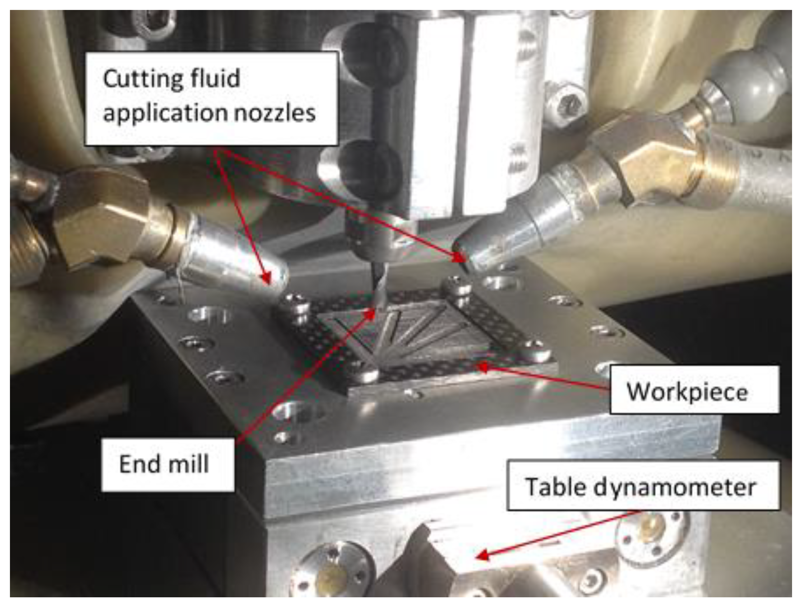
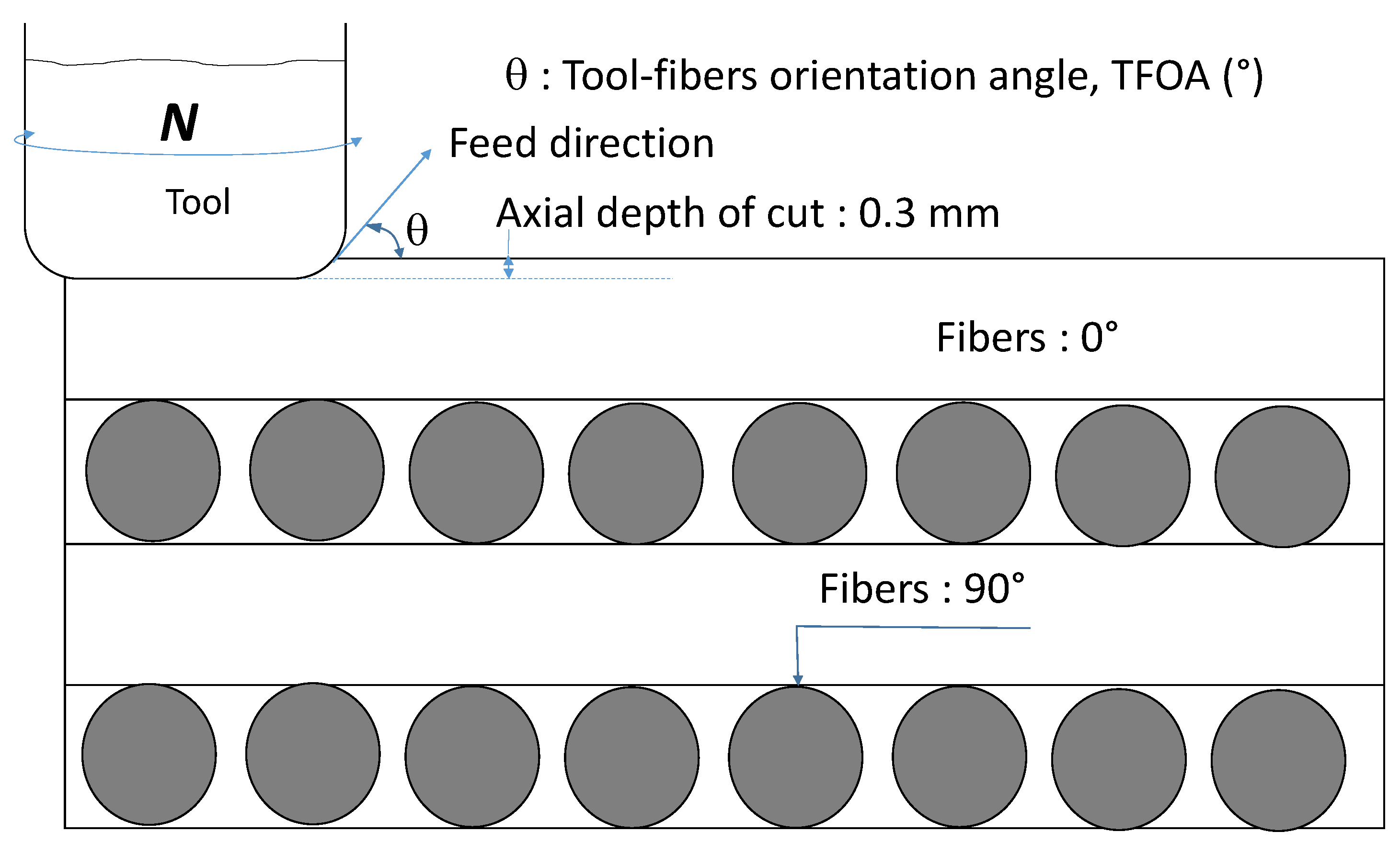
2.1. Machining Process Setup
2.2. Workpiece Materials and Cutting Tool
2.3. Measurement of Cutting Forces and Friction Angle
2.4. Edge Rounding Measurement
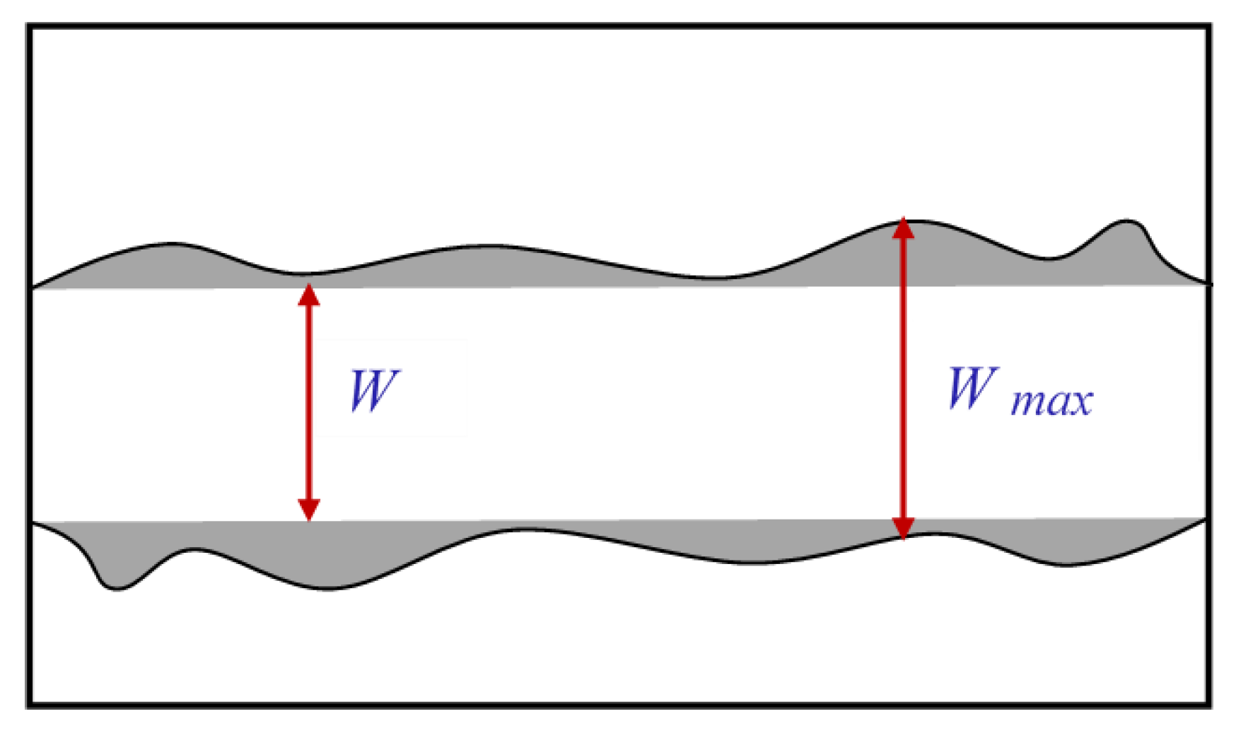
2.5. Delamination Measurement
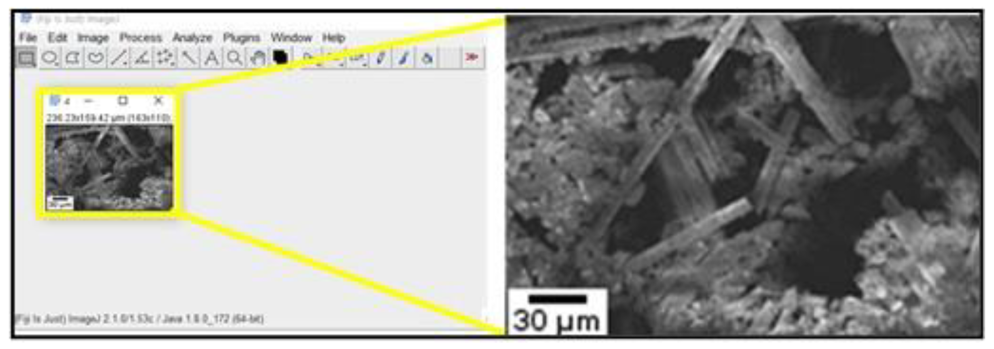
2.6. Chip Formation Characterization Processes
2.7. Experimental Design
- Spindle speed: 20,000 rpm
- Tool immersion: 100%
- Axial depth of cut: 0.3 mm
- Length of each slot: 22 mm
3. Results and Discussion
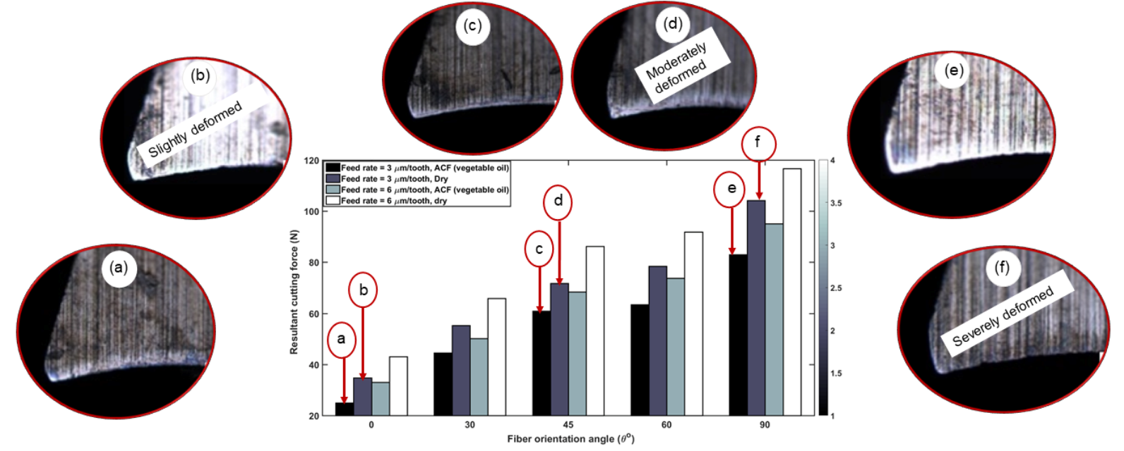
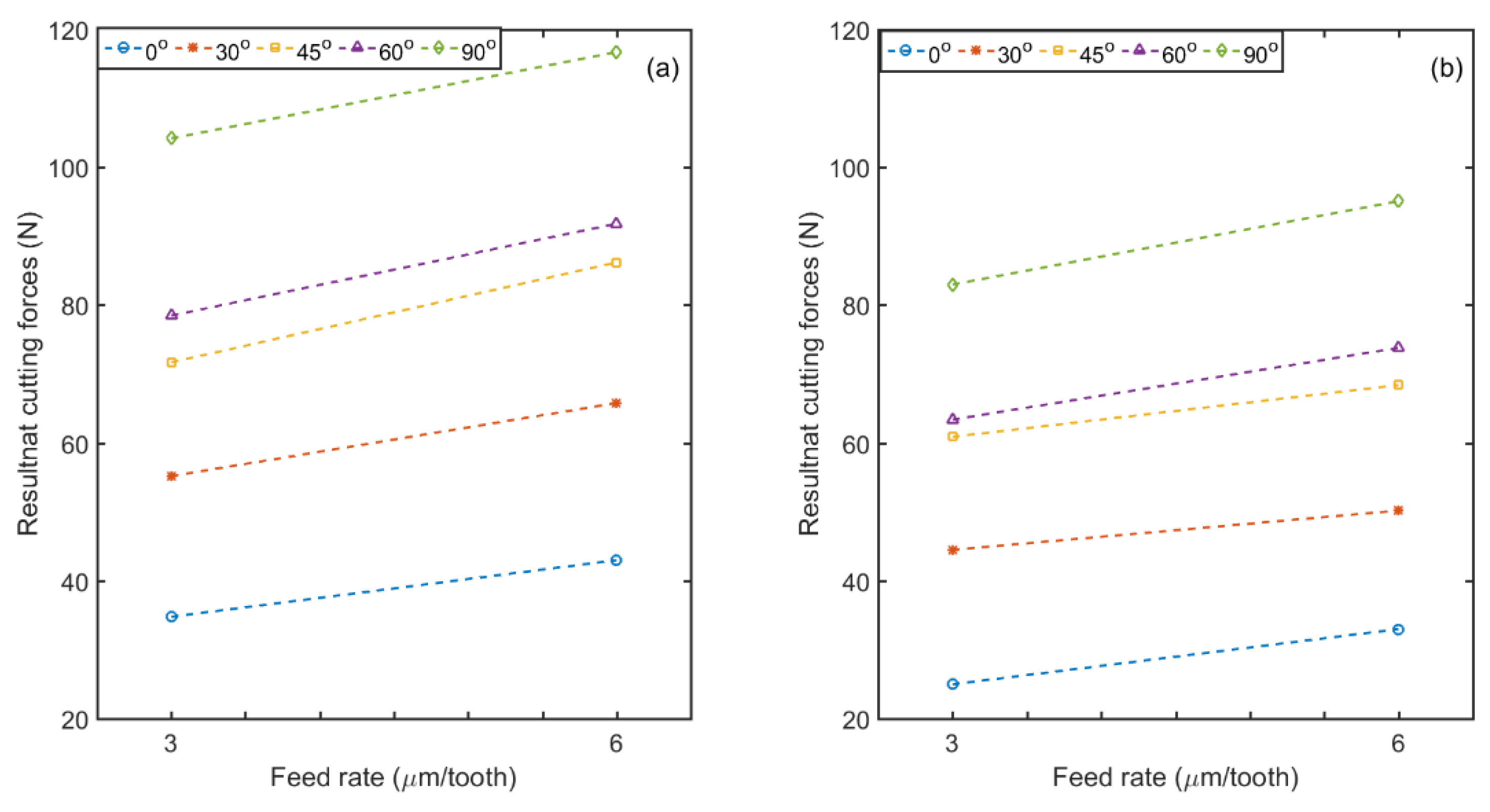
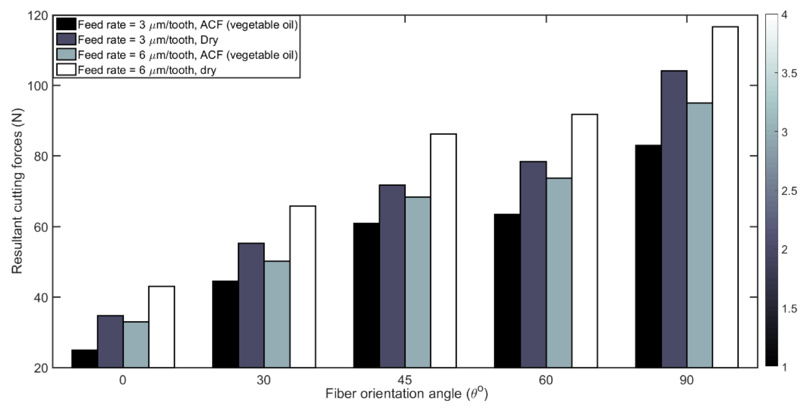
3.1. Cutting Forces
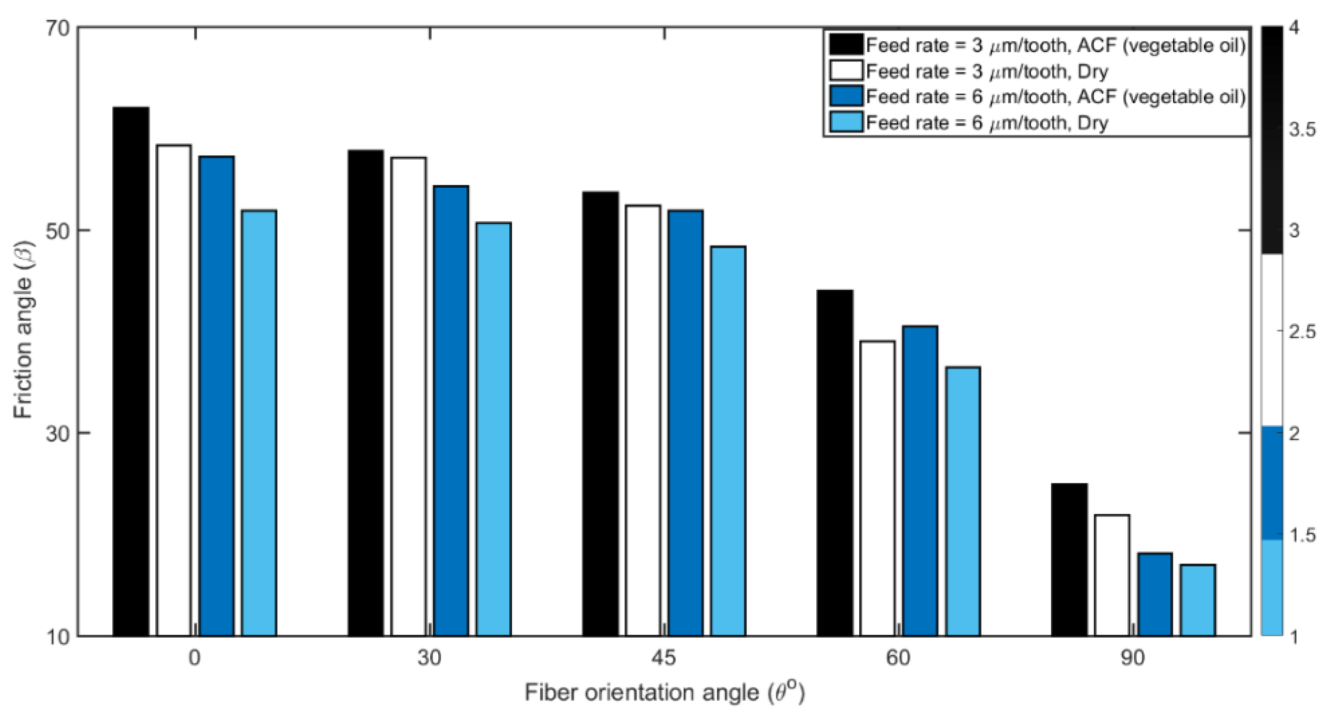
3.2. Friction Angle
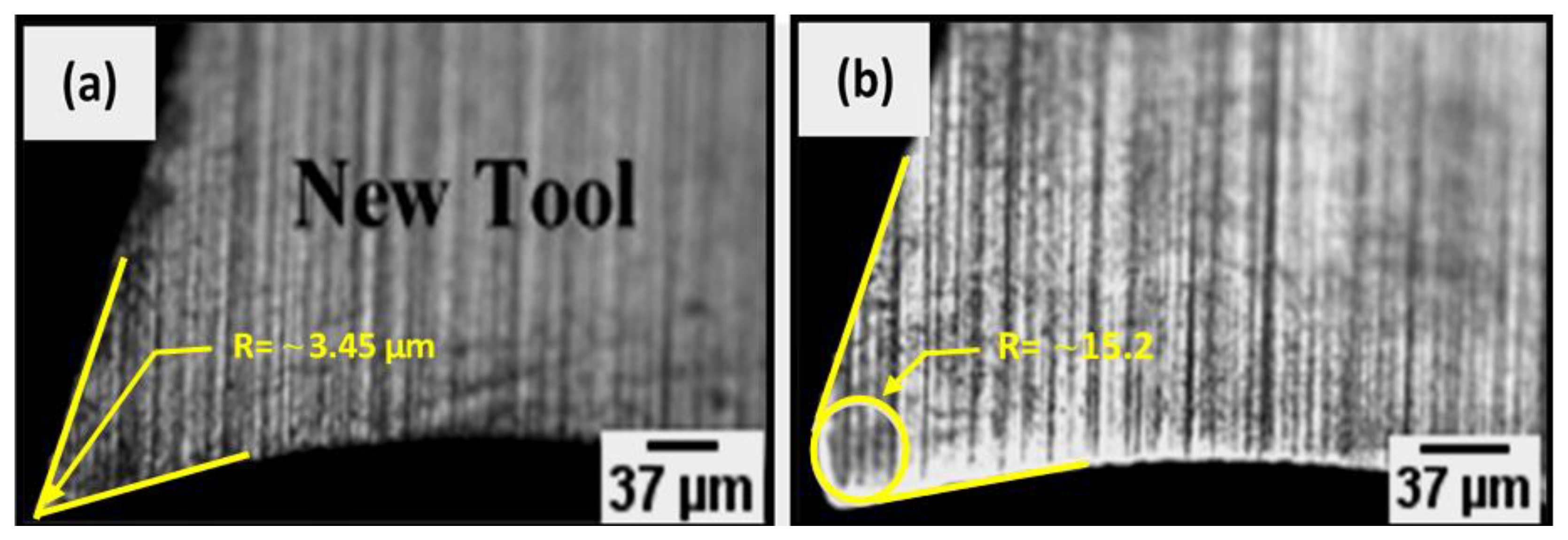
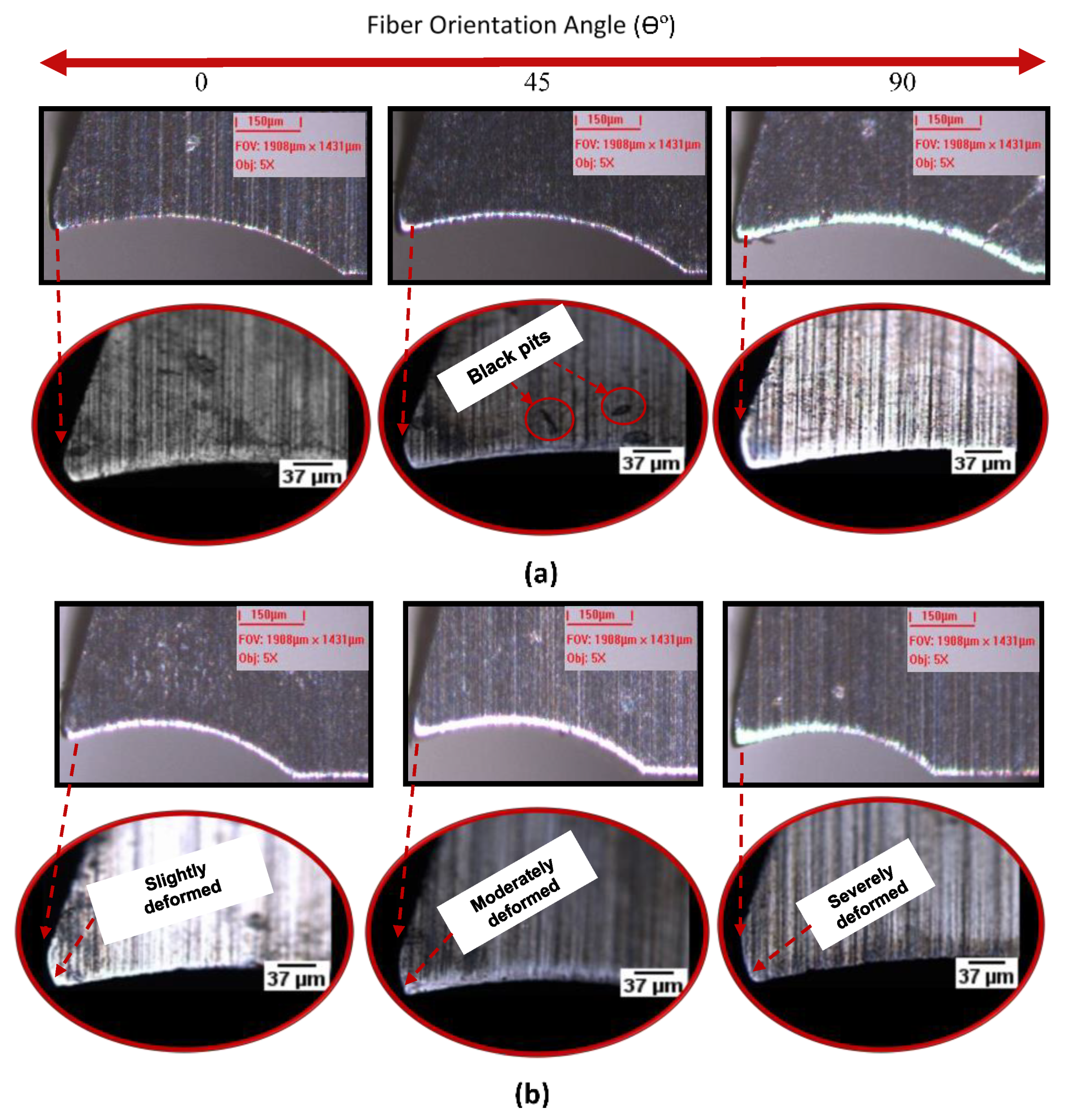
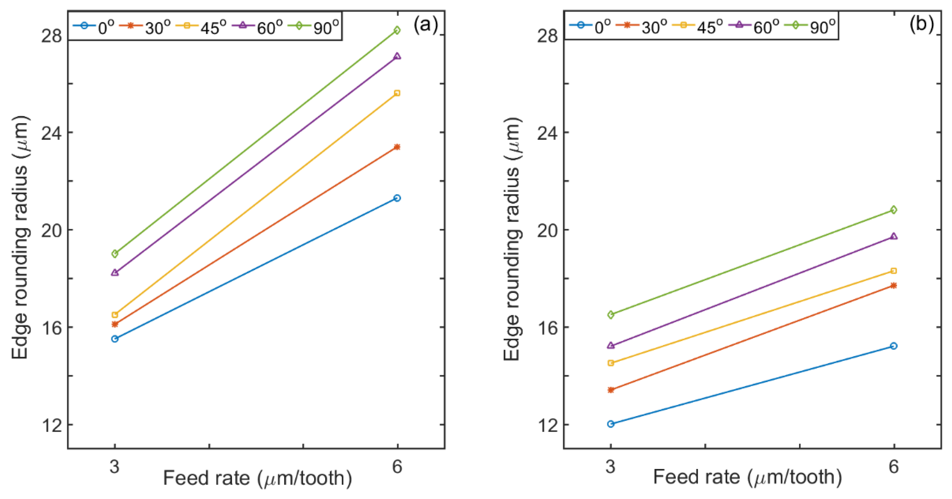
3.3. Tool Wear-Edge Rounding
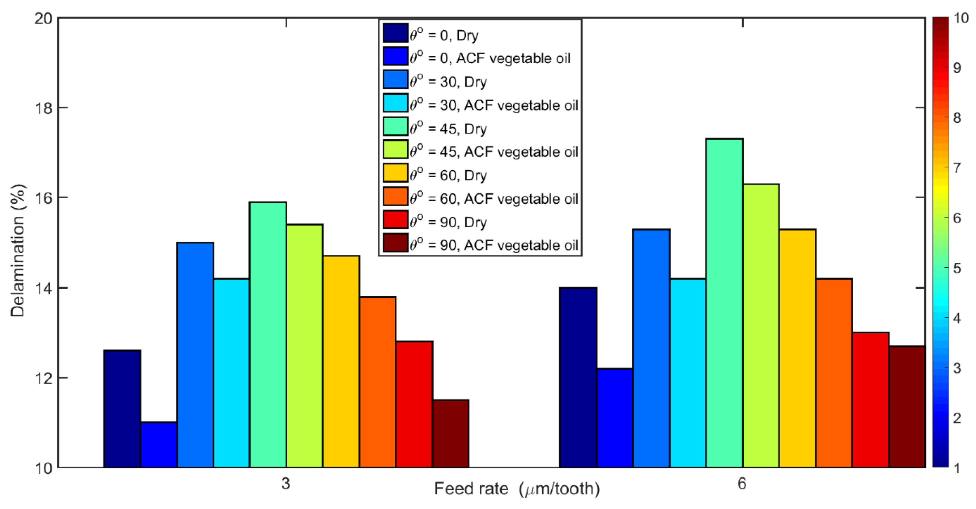
3.4. Delamination
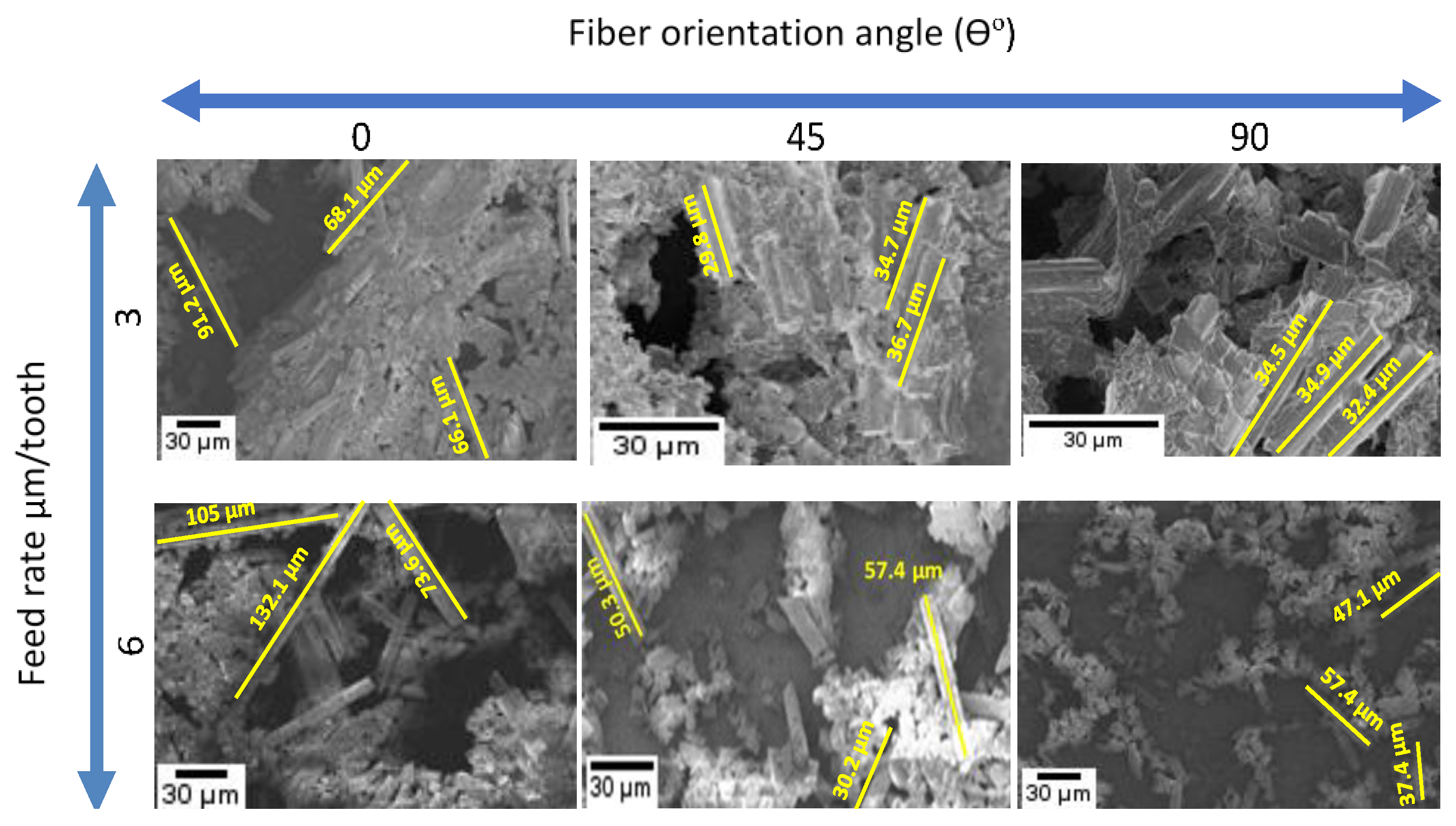
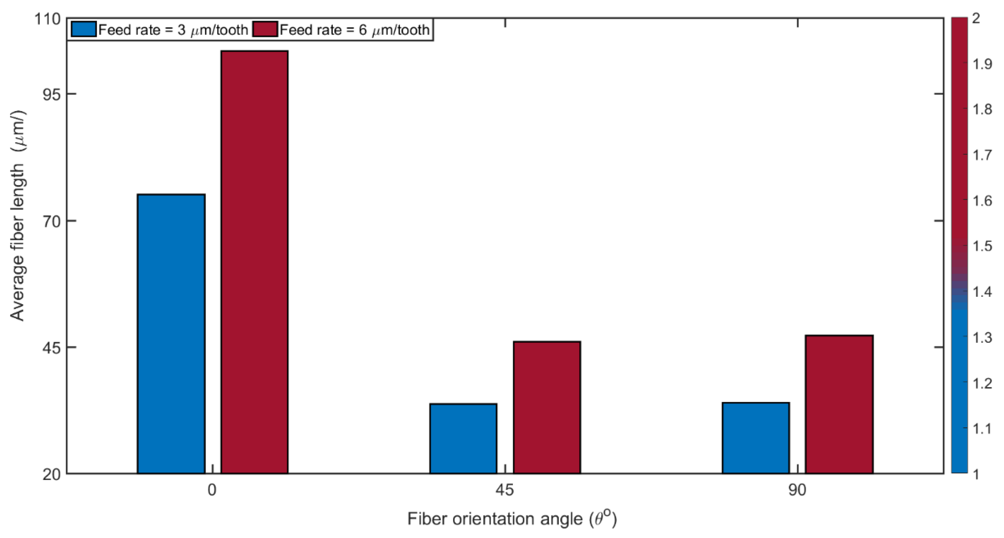
3.5. Chip Formation
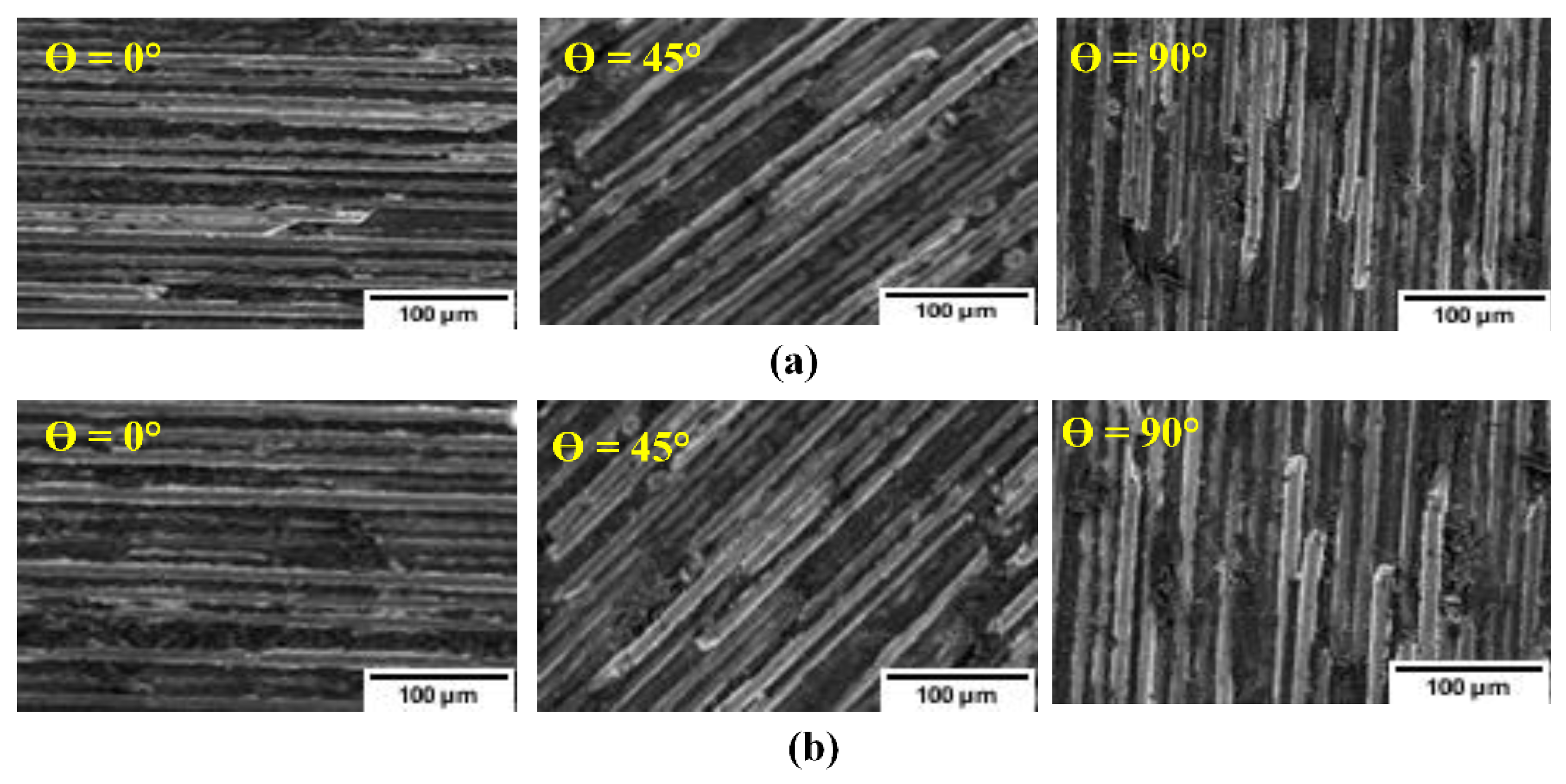
3.6. Impact of Fiber Orientation on CFRP Surface Finish
4. Conclusions
- (1)
- When machining CFRPs, the cutting direction, in relation to the fiber orientation, strongly influences chip formation, on which depends resistance to cutting, cutting force, fiber breakage, tool wear, the quality of the machined surface and the delamination. These indicators depend on the machining parameters used and on the cutting conditions.
- (2)
- The delamination percentage when cutting at TFOAs of 0°, 30° 45°, 60°, and 90° were improved by 65%, 91%, 54%, 66%, and 75%, respectively, under ACF (vegetable oil) conditions at 3µm/tooth. Machining with 45° TFOA produces maximum damage at high feed rate.
- (3)
- As expected, increase in feed rate increased the cutting force because of high chip load, especially in cutting directions where the fiber strength is high and with dry machining. Using a lubricant decreased the friction between the chip and the rake face of the tool, reduced the abrasive effect of broken fibers, and thus lowered cutting force and tool wear.
- (4)
- The magnitude of resultant cutting force was found to be greater in the dry condition relative to the ACF condition by about 23%, 31%, 26%, 25%, and 23%, respectively, for the samples in the 0°, 30, 45°, 60°, and 90° TFOA at 6 μm/tooth of feed rate. However, the use of atomized vegetable oil mixed with water improved the process performance compared to dry machining in that it reduced the cutting force, the delamination percentage and the tool edge rounding.
- (5)
- The tool damage was examined and measured using a 3D optical microscope (Olympus BXFM). 90° TFOA produced a large amount of tool edge rounding. Contrastingly, 0° TFOA has the least amount of edge rounding. However, the lowest values of edge radius evolution as a measure of the tool wear were 12 µm and 16.5 µm with TFOA from 0° to 90° at feed rate 3 µm/tooth under ACF (vegetable oil) conditions.
- (6)
- The findings of this study further support the use of the vegetable oil-in-water emulsion obtained through ultrasonic atomization as an effective and environmentally friendly lubricant for improving the machining of CFRPs.
Author Contributions
Funding
Institutional Review Board Statement
Informed Consent Statement
Data Availability Statement
Acknowledgments
Conflicts of Interest
Nomenclature
| CFRP | carbon fiber reinforced polymer | rpm | revolution per minute |
| ACF | atomization cutting fluid | shear angle (°) | |
| TFOA | Tool displacement direction-fiber orientation angle: θ (°) | α | rake angle (°) |
| Fx | normal force in the x direction | β | friction angle (°) |
| Fy | feed force in the y direction | N | newton |
| Fz | force in the z direction | µm | micrometer |
| Fc | cutting force | Dp | delamination percentage (%) |
| Ft | thrust force | Wmax | maximum damage width (mm) |
| R | resultant cutting force | W | original slot width (mm) |
References
- Hu, N.; Zhang, L. Some observations in grinding unidirectional carbon fibre-reinforced plastics. J. Mater. Process. Technol. 2004, 152, 333–338. [Google Scholar] [CrossRef]
- Wang, C.; Liu, G.; An, Q.; Chen, M. Occurrence and formation mechanism of surface cavity defects during orthogonal milling of CFRP laminates. Compos. Part B Eng. 2017, 109, 10–22. [Google Scholar] [CrossRef]
- Che, D.; Saxena, I.; Han, P.; Guo, P.; Ehmann, K.F. Machining of carbon fiber reinforced plastics/polymers: A literature review. J. Manuf. Sci. Eng. 2014, 136, 034001. [Google Scholar] [CrossRef]
- Dandekar, C.R.; Shin, Y.C. Modeling of machining of composite materials: A review. Int. J. Mach. Tools Manuf. 2012, 57, 102–121. [Google Scholar] [CrossRef]
- Bhatnagar, N.; Ramakrishnan, N.; Naik, N.; Komanduri, R. On the machining of fiber reinforced plastic (FRP) composite laminates. Int. J. Mach. Tools Manuf. 1995, 35, 701–716. [Google Scholar] [CrossRef]
- Rahman, M.; Ramakrishna, S.; Prakash, J.; Tan, D. Machinability study of carbon fiber reinforced composite. J. Mater. Process. Technol. 1999, 89, 292–297. [Google Scholar] [CrossRef]
- Santhanakrishnan, G.; Krishnamurthy, R.; Malhotra, S. Machinability characteristics of fibre reinforced plastics composites. J. Mech. Work. Technol. 1988, 17, 195–204. [Google Scholar] [CrossRef]
- Teti, R. Machining of composite materials. CIRP Ann. 2002, 51, 611–634. [Google Scholar] [CrossRef]
- Chen, W.-C. Some experimental investigations in the drilling of carbon fiber-reinforced plastic (CFRP) composite laminates. Int. J. Mach. Tools Manuf. 1997, 37, 1097–1108. [Google Scholar] [CrossRef]
- Ho-Cheng, H.; Dharan, C. Delamination during drilling in composite laminates. J. Manuf. Sci. Eng. 1990, 112, 236–239. [Google Scholar] [CrossRef]
- Shen, Z.; Lu, L.; Sun, J.; Yang, F.; Tang, Y.; Xie, Y. Wear patterns and wear mechanisms of cutting tools used during the manufacturing of chopped carbon fiber. Int. J. Mach. Tools Manuf. 2015, 97, 1–10. [Google Scholar] [CrossRef]
- Koenig, W.; Wulf, C.; Grass, P.; Willerscheid, H. Machining of fibre reinforced plastics. CIRP Ann. 1985, 34, 537–548. [Google Scholar] [CrossRef]
- Xu, W.-X.; Zhang, L.-C. Ultrasonic vibration-assisted machining: Principle, design and application. Adv. Manuf. 2015, 3, 173–192. [Google Scholar] [CrossRef]
- Ramulu, M.; Faridnia, M.; Garbini, J.; Jorgensen, J. Machining of graphite/epoxy composite materials with polycrystalline diamond (PCD) tools. J. Eng. Mater. Technol. 1991, 113, 430–436. [Google Scholar] [CrossRef]
- Wang, D.; Ramulu, M.; Arola, D. Orthogonal cutting mechanisms of graphite/epoxy composite. Part I: Unidirectional laminate. Int. J. Mach. Tools Manuf. 1995, 35, 1623–1638. [Google Scholar] [CrossRef]
- Wang, D.; Ramulu, M.; Arola, D. Orthogonal cutting mechanisms of graphite/epoxy composite. Part II: Multi-directional laminate. Int. J. Mach. Tools Manuf. 1995, 35, 1639–1648. [Google Scholar] [CrossRef]
- Calzada, K.A.; Kapoor, S.G.; DeVor, R.E.; Samuel, J.; Srivastava, A.K. Modeling and interpretation of fiber orientation-based failure mechanisms in machining of carbon fiber-reinforced polymer composites. J. Manuf. Process. 2012, 14, 141–149. [Google Scholar] [CrossRef]
- Geng, D.; Liu, Y.; Shao, Z.; Lu, Z.; Cai, J.; Li, X.; Jiang, X.; Zhang, D. Delamination formation, evaluation and suppression during drilling of composite laminates: A review. Compos. Struct. 2019, 216, 168–186. [Google Scholar] [CrossRef]
- Pwu, H.; Hocheng, H. Chip formation model of cutting fiber-reinforced plastics perpendicular to fiber axis. J. Manuf. Sci. Eng. 1998, 120, 192–196. [Google Scholar] [CrossRef]
- Turner, J.; Scaife, R.J.; El-Dessouky, H. Effect of machining coolant on integrity of CFRP composites. Adv. Manuf. Polym. Compos. Sci. 2015, 1, 54–60. [Google Scholar] [CrossRef] [Green Version]
- Ghafarizadeh, S.; Lebrun, G.; Chatelain, J.-F. Experimental investigation of the cutting temperature and surface quality during milling of unidirectional carbon fiber reinforced plastic. J. Compos. Mater. 2016, 50, 1059–1071. [Google Scholar] [CrossRef]
- Liu, J.; Chen, G.; Ji, C.; Qin, X.; Li, H.; Ren, C. An investigation of workpiece temperature variation of helical milling for carbon fiber reinforced plastics (CFRP). Int. J. Mach. Tools Manuf. 2014, 86, 89–103. [Google Scholar] [CrossRef]
- Hocheng, H.; Puw, H.; Huang, Y. Preliminary study on milling of unidirectional carbon fibre-reinforced plastics. Compos. Manuf. 1993, 4, 103–108. [Google Scholar] [CrossRef]
- Takeyama, H.; Iijima, N. Machinability of glassfiber reinforced plastics and application of ultrasonic machining. CIRP Ann. 1988, 37, 93–96. [Google Scholar] [CrossRef]
- Wang, X.M.; Zhang, L. An experimental investigation into the orthogonal cutting of unidirectional fibre reinforced plastics. Int. J. Mach. Tools Manuf. 2003, 43, 1015–1022. [Google Scholar] [CrossRef]
- Zhang, L.; Zhang, H.; Wang, X. A force prediction model for cutting unidirectional fibre-reinforced plastics. Mach. Sci. Technol. 2001, 5, 293–305. [Google Scholar] [CrossRef]
- Lopez de Lacalle, N.; Lamikiz, A.; Campa, F.; Valdivielso, A.F.; Etxeberria, I. Design and test of a multitooth tool for CFRP milling. J. Compos. Mater. 2009, 43, 3275–3290. [Google Scholar] [CrossRef]
- Sheikh-Ahmad, J.; Yadav, R. Model for predicting cutting forces in machining CFRP. Int. J. Mater. Prod. Technol. 2008, 32, 152–167. [Google Scholar] [CrossRef]
- Karpat, Y.; Bahtiyar, O.; Değer, B. Mechanistic force modeling for milling of unidirectional carbon fiber reinforced polymer laminates. Int. J. Mach. Tools Manuf. 2012, 56, 79–93. [Google Scholar] [CrossRef]
- Shahrajabian, H.; Hadi, M.; Farahnakian, M. Experimental investigation of machining parameters on machinability of carbon fiber/epoxy composites. Int. J. Eng. Innov. Technol. 2012, 3, 30–36. [Google Scholar]
- Caggiano, A.; Improta, I.; Nele, L. Characterization of a new dry drill-milling process of Carbon Fibre Reinforced Polymer laminates. Materials 2018, 11, 1470. [Google Scholar] [CrossRef] [PubMed] [Green Version]
- Ismail, S.O.; Sarfraz, S.; Niamat, M.; Mia, M.; Gupta, M.K.; Pimenov, D.Y.; Shehab, E. Comprehensive study on tool wear during machining of fiber-reinforced polymeric composites. In Machining and Machinability of Fiber Reinforced Polymer Composites; Springer: Singapore, 2021; pp. 129–147. [Google Scholar]
- Xia, T.; Kaynak, Y.; Arvin, C.; Jawahir, I. Cryogenic cooling-induced process performance and surface integrity in drilling CFRP composite material. Int. J. Adv. Manuf. Technol. 2016, 82, 605–616. [Google Scholar] [CrossRef]
- Basmaci, G.; Yoruk, A.S.; Koklu, U.; Morkavuk, S. Impact of cryogenic condition and drill diameter on drilling performance of CFRP. Appl. Sci. 2017, 7, 667. [Google Scholar] [CrossRef] [Green Version]
- Impero, F.; Dix, M.; Squillace, A.; Prisco, U.; Palumbo, B.; Tagliaferri, F. A comparison between wet and cryogenic drilling of CFRP/Ti stacks. Mater. Manuf. Process. 2018, 33, 1354–1360. [Google Scholar] [CrossRef]
- Iqbal, A.; Zhao, G.; Zaini, J.; Gupta, M.; Jamil, M.; He, N.; Nauman, M.; Mikolajczyk, T.; Pimenov, D. Between-the-holes cryogenic cooling of the tool in hole-making of Ti-6Al-4V and CFRP. Materials 2021, 14, 795. [Google Scholar] [CrossRef]
- Joshi, S.; Rawat, K.; Balan, A. A novel approach to predict the delamination factor for dry and cryogenic drilling of CFRP. J. Mater. Process. Technol. 2018, 262, 521–531. [Google Scholar] [CrossRef]
- Khairussaleh, N.K.M.; Haron, C.H.C.; Ghani, J.A. Study on wear mechanism of solid carbide cutting tool in milling CFRP. J. Mater. Res. 2016, 31, 1893. [Google Scholar] [CrossRef]
- Khairusshima, M.N.; Hassan, C.C.; Jaharah, A.; Amin, A.; Idriss, A.M. Effect of chilled air on tool wear and workpiece quality during milling of carbon fibre-reinforced plastic. Wear 2013, 302, 1113–1123. [Google Scholar] [CrossRef]
- Siniawski, M.T.; Saniei, N.; Adhikari, B.; Doezema, L.A. Influence of fatty acid composition on the tribological performance of two vegetable-based lubricants. J. Synth. Lubr. 2007, 24, 101–110. [Google Scholar] [CrossRef]
- Zimmerman, J.B.; Clarens, A.F.; Hayes, K.F.; Skerlos, S.J. Design of hard water stable emulsifier systems for petroleum-and bio-based semi-synthetic metalworking fluids. Environ. Sci. Technol. 2003, 37, 5278–5288. [Google Scholar] [CrossRef]
- Abdalla, H.; Baines, W.; McIntyre, G.; Slade, C. Development of novel sustainable neat-oil metal working fluids for stainless steel and titanium alloy machining. Part 1. Formulation development. Int. J. Adv. Manuf. Technol. 2007, 34, 21–33. [Google Scholar] [CrossRef]
- Shashidhara, Y.; Jayaram, S. Vegetable oils as a potential cutting fluid—An evolution. Tribol. Int. 2010, 43, 1073–1081. [Google Scholar] [CrossRef]
- Alves, S.M.; de Oliveira, J.F.G. Development of new cutting fluid for grinding process adjusting mechanical performance and environmental impact. J. Mater. Process. Technol. 2006, 179, 185–189. [Google Scholar] [CrossRef]
- Gryglewicz, S.; Piechocki, W.; Gryglewicz, G. Preparation of polyol esters based on vegetable and animal fats. Bioresour. Technol. 2003, 87, 35–39. [Google Scholar] [CrossRef]
- Kamogawa, K.; Akatsuka, H.; Matsumoto, M.; Yokoyama, S.; Sakai, T.; Sakai, H.; Abe, M. Surfactant-free O/W emulsion formation of oleic acid and its esters with ultrasonic dispersion. Colloids Surf. A Physicochem. Eng. Asp. 2001, 180, 41–53. [Google Scholar] [CrossRef]
- Sakai, T. Surfactant-free emulsions. Curr. Opin. Colloid Interface Sci. 2008, 13, 228–235. [Google Scholar] [CrossRef]
- Elgnemi, T.; Ahmadi, K.; Songmene, V.; Nam, J.; Jun, M.B. Effects of atomization-based cutting fluid sprays in milling of carbon fiber reinforced polymer composite. J. Manuf. Process. 2017, 30, 133–140. [Google Scholar] [CrossRef]
- Jun, M.B.; Joshi, S.S.; DeVor, R.E.; Kapoor, S.G. An experimental evaluation of an atomization-based cutting fluid application system for micromachining. J. Manuf. Sci. Eng. 2008, 130, 031118. [Google Scholar] [CrossRef]
- Burton, G.; Goo, C.-S.; Zhang, Y.; Jun, M.B. Use of vegetable oil in water emulsion achieved through ultrasonic atomization as cutting fluids in micro-milling. J. Manuf. Process. 2014, 16, 405–413. [Google Scholar] [CrossRef]
- Rukosuyev, M.; Goo, C.S.; Jun, M.B. Understanding the effects of the system parameters of an ultrasonic cutting fluid application system for micro-machining. J. Manuf. Process. 2010, 12, 92–98. [Google Scholar] [CrossRef]
- Maegawa, S.; Morikawa, Y.; Hayakawa, S.; Itoigawa, F.; Nakamura, T. Mechanism for changes in cutting forces for down-milling of unidirectional carbon fiber reinforced polymer laminates: Modeling and experimentation. Int. J. Mach. Tools Manuf. 2016, 100, 7–13. [Google Scholar] [CrossRef]
- Sheikh-Ahmad, J.Y. Machining of Polymer Composites; Springer: New York, NY, USA, 2009; Volume 387355391. [Google Scholar]
- Wang, X.; Zhang, L. Machining damage in unidirectional fibre-reinforced plastics. In Abrasive Technology: Current Development and Applications I; World Scientific Publishing Co Pte Ltd.: Singapore, 1999; pp. 429–436. [Google Scholar]
- Liu, Y.; Deng, J.; Wu, F.; Duan, R.; Zhang, X.; Hou, Y. Wear resistance of carbide tools with textured flank-face in dry cutting of green alumina ceramics. Wear 2017, 372, 91–103. [Google Scholar] [CrossRef]
- Zhao, X.; Li, Y. Tool Wear Pattern and Mechanics in High Speed Cutting Microwave Printed Circuit Board. Key Eng. Mater. 2010, 426, 515–519. [Google Scholar] [CrossRef]
- Nguyen, D.; Abdullah, M.S.B.; Khawarizmi, R.; Kim, D.; Kwon, P. The effect of fiber orientation on tool wear in edge-trimming of carbon fiber reinforced plastics (CFRP) laminates. Wear 2020, 450, 203213. [Google Scholar] [CrossRef]
- Shirazinia, M.; Moya, R.; Muñoz, F. Properties of laminated curves manufactured with steamed veneers from fast-growth tropical wood in Costa Rica. Madera Y Bosques 2011, 17, 85–101. [Google Scholar] [CrossRef]
- Kumar, D.; Gururaja, S. Machining damage and surface integrity evaluation during milling of UD-CFRP laminates: Dry vs Cryogenic. Compos. Struct. 2020, 247, 112504. [Google Scholar] [CrossRef]
- Xiao, J.; Gao, C.; Ke, Y. An analytical approach to cutting force prediction in milling of carbon fiber reinforced polymer laminates. Mach. Sci. Technol. 2018, 22, 1012–1028. [Google Scholar] [CrossRef]
- Niknam, S.A.; Songmene, V. Analysis of friction and burr formation in slot milling. Procedia CIRP 2014, 17, 755–759. [Google Scholar] [CrossRef] [Green Version]
- Faraz, A.; Biermann, D.; Weinert, K. Cutting edge rounding: An innovative tool wear criterion in drilling CFRP composite laminates. Int. J. Mach. Tools Manuf. 2009, 49, 1185–1196. [Google Scholar] [CrossRef]
- Zitoune, R.; Krishnaraj, V.; Almabouacif, B.S.; Collombet, F.; Sima, M.; Jolin, A. Influence of machining parameters and new nano-coated tool on drilling performance of CFRP/Aluminium sandwich. Compos. Part. B Eng. 2012, 43, 1480–1488. [Google Scholar] [CrossRef]
- Nguyen, D.; Voznyuk, V.; Bin Abdullah, M.S.; Kim, D.; Kwon, P.Y. Tool Wear of Superhard Ceramic Coated Tools in Drilling of CFRP/Ti Stacks. In Proceedings of the International Manufacturing Science and Engineering Conference, Erie, PA, USA, 10–14 June 2019; American Society of Mechanical Engineers: New York, NY, USA, 2019; p. V002T003A089. [Google Scholar]
- Swan, S.; Bin Abdullah, M.S.; Kim, D.; Nguyen, D.; Kwon, P. Tool wear of advanced coated tools in drilling of CFRP. J. Manuf. Sci. Eng. 2018, 140, 111018-1. [Google Scholar] [CrossRef]
- Maegawa, S.; Morikawa, Y.; Hayakawa, S.; Itoigawa, F.; Nakamura, T. Effects of fiber orientation direction on tool-wear processes in down-milling of carbon fiber-reinforced plastic laminates. Int. J. Autom. Technol. 2015, 9, 356–364. [Google Scholar] [CrossRef]
- Rawat, S.; Attia, H. Wear mechanisms and tool life management of WC–Co drills during dry high speed drilling of woven carbon fibre composites. Wear 2009, 267, 1022–1030. [Google Scholar] [CrossRef]
- Ramulu, M.; Kim, D.; Choi, G. Frequency analysis and characterization in orthogonal cutting of glass fiber reinforced composites. Compos. Part. A Appl. Sci. Manuf. 2003, 34, 949–962. [Google Scholar] [CrossRef]
- Davim, J.P.; Mata, F. Optimisation of surface roughness on turning fibre-reinforced plastics (FRPs) with diamond cutting tools. Int. J. Adv. Manuf. Technol. 2005, 26, 319–323. [Google Scholar] [CrossRef]
- Liu, G.; Chen, H.; Huang, Z.; Gao, F.; Chen, T. Surface quality of staggered PCD end mill in milling of carbon fiber reinforced plastics. Appl. Sci. 2017, 7, 199. [Google Scholar] [CrossRef]
- Hintze, W.; Hartmann, D. Modeling of delamination during milling of unidirectional CFRP. Procedia Cirp 2013, 8, 444–449. [Google Scholar] [CrossRef] [Green Version]
- Hintze, W.; Cordes, M.; Koerkel, G. Influence of weave structure on delamination when milling CFRP. J. Mater. Process. Technol. 2015, 216, 199–205. [Google Scholar] [CrossRef]
- Chang, C.-S. Turning of glass–fiber reinforced plastics materials with chamfered main cutting edge carbide tools. J. Mater. Process. Technol. 2006, 180, 117–129. [Google Scholar] [CrossRef]
- Pecat, O.; Rentsch, R.; Brinksmeier, E. Influence of milling process parameters on the surface integrity of CFRP. Procedia Cirp 2012, 1, 466–470. [Google Scholar] [CrossRef] [Green Version]


| Cutter Diameter | Flute Length | Shank Diameter | Overall Length | Rake Angle | Helix Angle |
|---|---|---|---|---|---|
| 0.125 in | 0.250 in | 1/8 in | 1.50 in | 7° | 30° |
| 3.175 mm | 6.35 mm | 3.175 mm | 38.1 mm |
| Ident. | Control Variables | Levels | Response Variables |
|---|---|---|---|
| A B C | Fiber orientation (Ɵ°) Feed rate (µm/tooth) Cutting fluids | 0, 30, 45, 60, 90 3, 6 Dry-ACF (vegetable oil) | 1. Cutting forces 2. Tool wear 3. Delamination 4. Surface damage 5. Chip formation |
Publisher’s Note: MDPI stays neutral with regard to jurisdictional claims in published maps and institutional affiliations. |
© 2021 by the authors. Licensee MDPI, Basel, Switzerland. This article is an open access article distributed under the terms and conditions of the Creative Commons Attribution (CC BY) license (https://creativecommons.org/licenses/by/4.0/).
Share and Cite
Elgnemi, T.-S.-M.; Jun, M.B.-G.; Songmene, V.; Samuel, A.M. Milling Performance of CFRP Composite and Atomised Vegetable Oil as a Function of Fiber Orientation. Materials 2021, 14, 2062. https://doi.org/10.3390/ma14082062
Elgnemi T-S-M, Jun MB-G, Songmene V, Samuel AM. Milling Performance of CFRP Composite and Atomised Vegetable Oil as a Function of Fiber Orientation. Materials. 2021; 14(8):2062. https://doi.org/10.3390/ma14082062
Chicago/Turabian StyleElgnemi, Tarek-Shaban-Mohamed, Martin Byung-Guk Jun, Victor Songmene, and Agnes Marie Samuel. 2021. "Milling Performance of CFRP Composite and Atomised Vegetable Oil as a Function of Fiber Orientation" Materials 14, no. 8: 2062. https://doi.org/10.3390/ma14082062