3.2.1. EBSD Analysis of the Microscopic Structure
The microstructural characteristics of the tested alloys at peak aging are presented in
Figure 3. The grains present an obvious growth trend, with average grain sizes of 12 μm, 22 μm, 30 μm and 200 μm, respectively. Furthermore, the average grain size of the NC-4 alloy is almost 15 times that of the NC-1 alloy, as shown in
Figure 3e,h. In general, the grains are evenly distributed inside the alloy after heat treatment, the grains of the NC-2 and NC-3 alloys are uniform and have no obvious directionality, showing a standard normal distribution in
Figure 3f,g. However, the grains of the NC-1 alloy are distributed along the rolling direction in some regions, as shown in
Figure 3a. Moreover, recrystallized grains are observed in the NC-1 alloy, but few are observed in others, which means the appropriate Co can accelerate the recrystallization process. The uneven grain distribution of the NC-1 alloy causes incompatible plastic deformation and local stress concentrations. Compared with that of the NC-4 alloy, the grain size of the other alloys reduces significantly, indicating that effectively Co promotes the inhibition of grain growth and the refinement of alloy microstructure.
3.2.2. Microstructure Observation by TEM
Figure 4 shows TEM images of the tested alloys at the peak aging state along the [001]
Cu. direction A large number of precipitated particles are uniformly dispersed, and a small number of dislocation entanglements are distributed in the matrix. The precipitated particles in the four alloys are all bean-shaped, but there are certain differences in size, as shown in
Figure 4a–d. Furthermore, the four alloys share the same selected area electron diffraction (SAED) pattern images. As illustrated by the corresponding patterns in
Figure 4e,h, there are two sets of spots in addition to the matrix spots, marked as red A and blue B, respectively. Point A is located at the intersection of the centerline of the matrix spots, while Point B is close to the matrix spots. According to the calibration results, the two sets of spots are the same precipitated phase δ-(Ni, Co)
2Si in the NC-1, NC-2 and NC-3 alloys, with an orthorhombic structure of two variant forms δ
1 and δ
2. Similarly, the spots in the NC-4 alloy are all the same precipitated phase δ-Ni
2Si with two variants of δ
1 and δ
2, which is consistent with the previous results [
4,
20]. The orientation relationships (ORs) of the precipitates and matrix can be calibrated as (220)
Cu//(
)
δ1//(
)
δ2 and [
]
Cu//[
]
δ1//[
]
δ2.
In order to further confirm the microstructure of the precipitated phase, the NC-3 and NC-4 alloys were selected as an example, as shown in
Figure 5.
Figure 5c,f presents the SAED patterns of δ-(Ni, Co)
2Si and δ-Ni
2Si phases along the [112]
Cu direction are the same, which is consistent with the calibration results of the [001]
Cu direction. Hence, the results indicate δ-(Ni, Co)
2Si and δ-Ni
2Si phases share the same orthorhombic structure and ORs with the matrix. The corresponding ORs of the precipitates and matrix can be calibrated as (
)
Cu//(
)
δ1//(
)
δ2, [112]
Cu//[012]
δ1//[010]
δ2. According to the dark-field images of
Figure 5b,e, the precipitated phases present a mutually perpendicular position relationship along the [001]
Cu direction. In addition, the precipitated phases are distributed at an angle of 120 degrees and all parallel to the <110>
Cu along the [111]
Cu direction, as shown in
Figure 5c,f. Comparing the dark-field images of the two alloys, the addition of Co is an active player of precipitation as the number density of precipitates in the NC-3 alloy being larger than that of the NC-4 alloy.
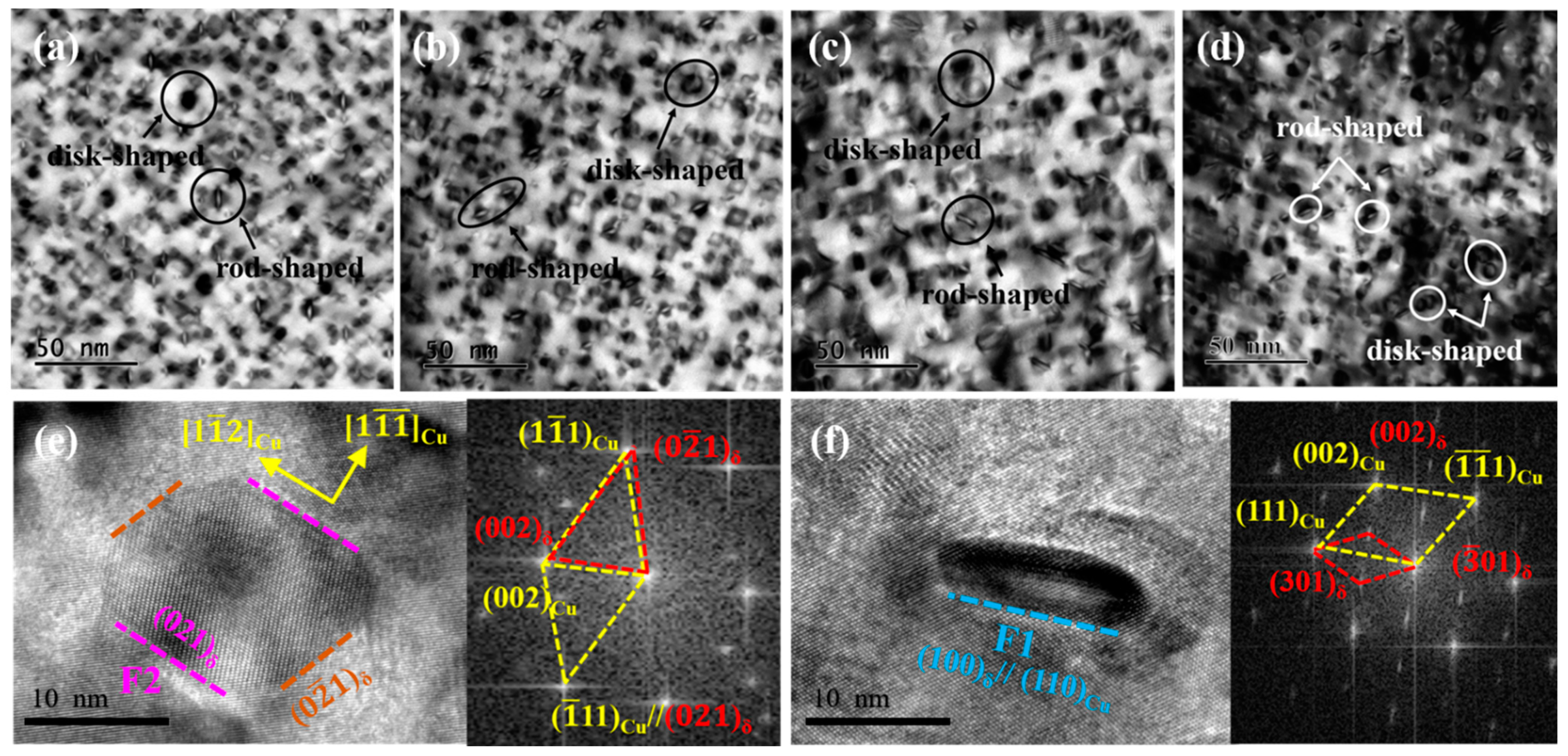
A large number of precipitated phases can be clearly observed from the TEM images along the [110]
Cu direction in
Figure 6a,d, which are distributed uniformly in the matrix. Compared with the bright-field images of the four alloys, the precipitated phases share the same morphological features, except for the size, which are both rod-shaped and disk-shaped structures, respectively. The HRTEM images in
Figure 6e,f show that two precipitated phases along the [110]
Cu direction are located on the (
)
δ and (
)
δ crystal planes, respectively. According to the corresponding Fourier transform in
Figure 6e, an angle deviation of 2–3° is observed between the (
)
δ and (
)
Cu crystal planes, while the (
)
δ and (
)
Cu crystal planes remain parallel, and the precipitated phases are still located on the (110)
Cu crystal planes. This indicates that the ORs between precipitates and matrix are deflected with the aging process, resulting in the variation of growth direction.
Combined with the previous analysis, different morphologies of the precipitates were mainly ascribed to various growth directions [
21]. From the Fourier transform results, the precipitate with the ORs of (
)
Cu//(
)
δ and [
]
Cu//[
]
δ tends to grow in a two-dimensional plane with a disk shape, while that with the ORs of (
)
Cu//(
)
δ and [
]
Cu//[
]
δ grows in a one-dimensional direction to form a rod shape. Caused by the diffusion during the phase transformation, the change in the lattice parameters of the precipitates results in an angle deviation of the or between the precipitates and matrix. Under the principle of energy minimum, the precipitates will preferentially grow along with the direction of the lowest energy, which exhibits two different morphologies eventually [
22].
Figure 7 shows the statistics of the grains and precipitates of the tested alloys at the peak aging state. Compared with the four alloys in
Figure 7a, the grain size of the alloys keeps growing gradually, among which the NC-4 alloy has the largest grain. In addition, the precipitated phase fluctuates within the range of 9–15 nm, and the average particle size of the NC-2 and NC-3 alloys is relatively close, 11.45 and 12.25 nm, respectively. Compared with the NC-4 alloy in
Figure 7b, the volume fraction of precipitates in the NC-1, NC-2 and NC-3 alloys increases significantly. For example, the volume fraction of precipitates in the NC-3 alloy is twice that of the NC-4 alloy, 7.08% and 3.86%, respectively. Moreover, the increase in dislocation caused by rolling deformation is also calculated, and those of the four alloys are all in the order of magnitude of 10
13. In conclusion, compared with the NC-4 alloy without Co, the volume fraction of precipitates in the alloy with Co is significantly improved, accompanied by an increase in the precipitated phase size. This indicates that the addition of Co promotes the precipitation of the precipitated phase and further purifies the matrix.


 ,
, 


