
Development of 3D Slurry Printing Technology with Submersion-Light Apparatus in Dental Application

 , , and
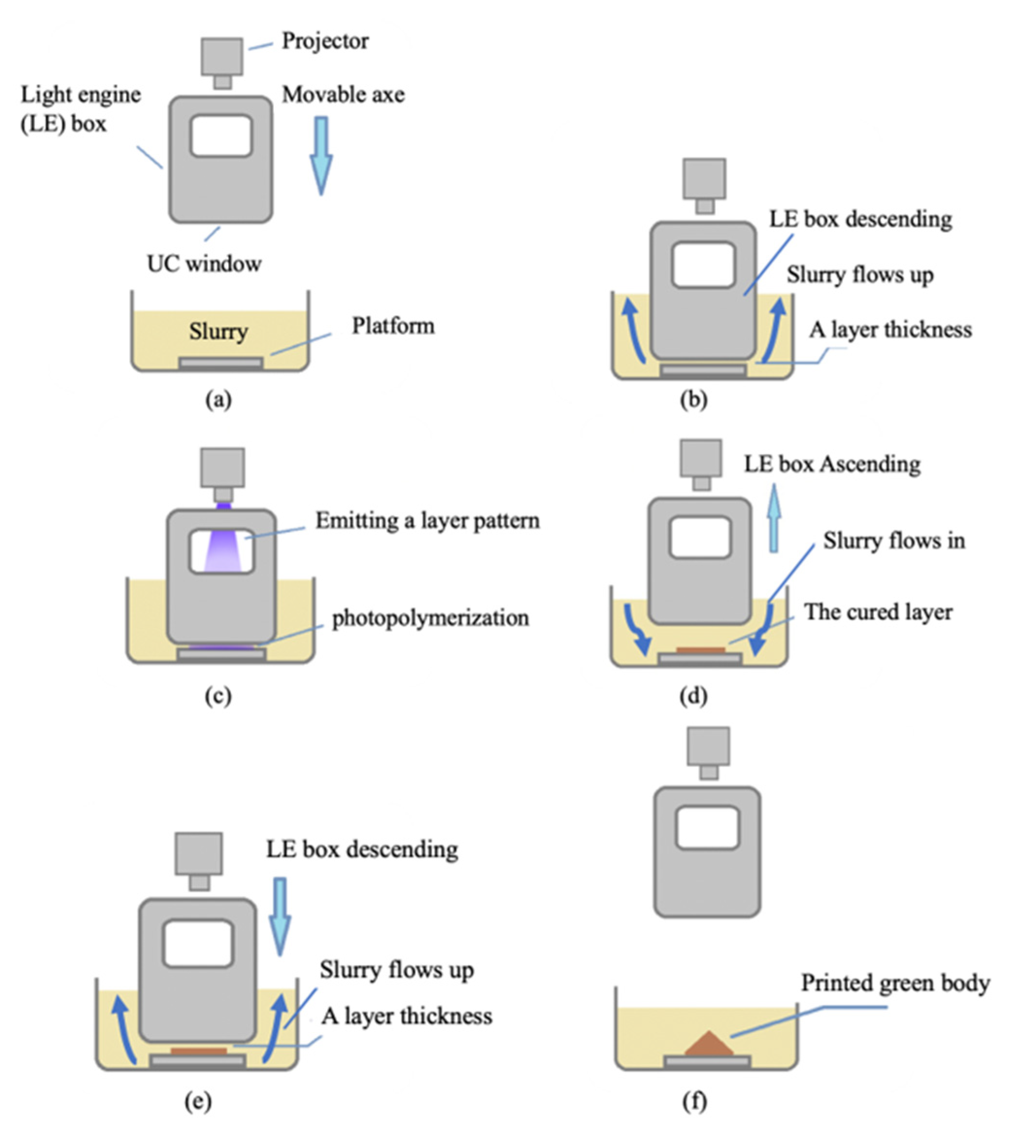
Abstract
:1. Introduction
2. Materials and Methods
2.1. Submersion-Light Three-Dimensional Slurry Printing Method
2.2. Mechanical Design of the Proposed Printer
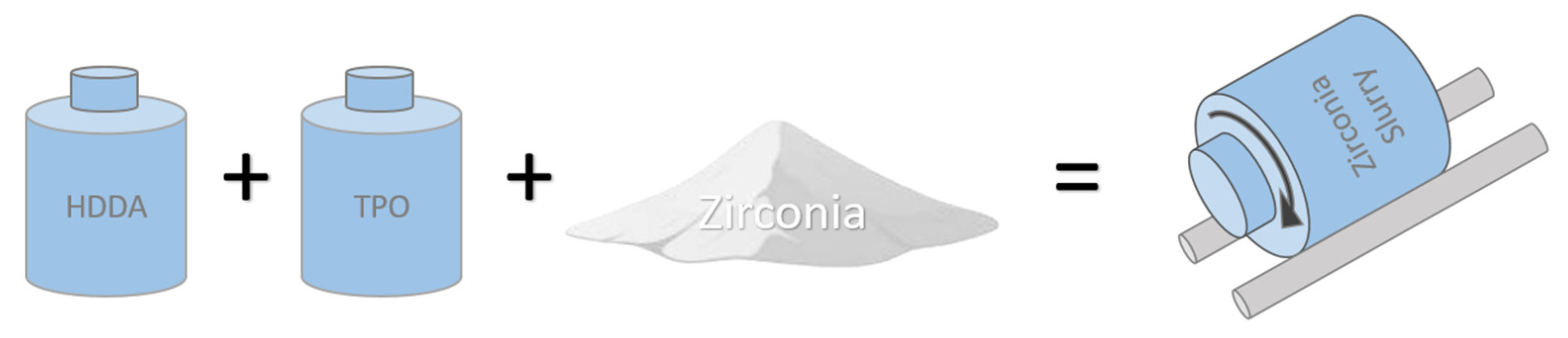
2.3. Material Preparation
2.4. Physical Property Measurement
2.4.1. Viscosity
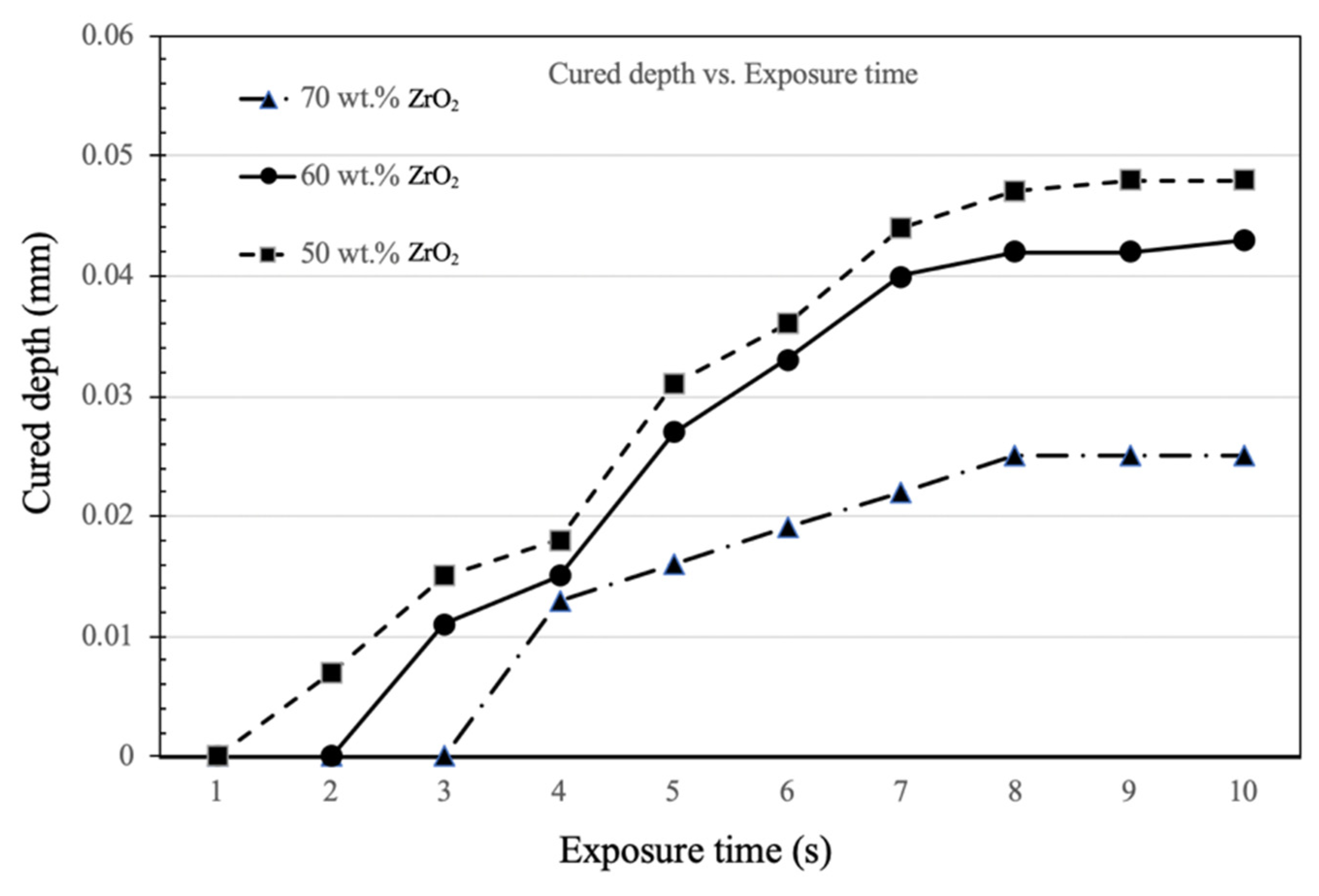
2.4.2. Slurry Curing Test
2.4.3. Microstructural Observations and Mechanical Properties
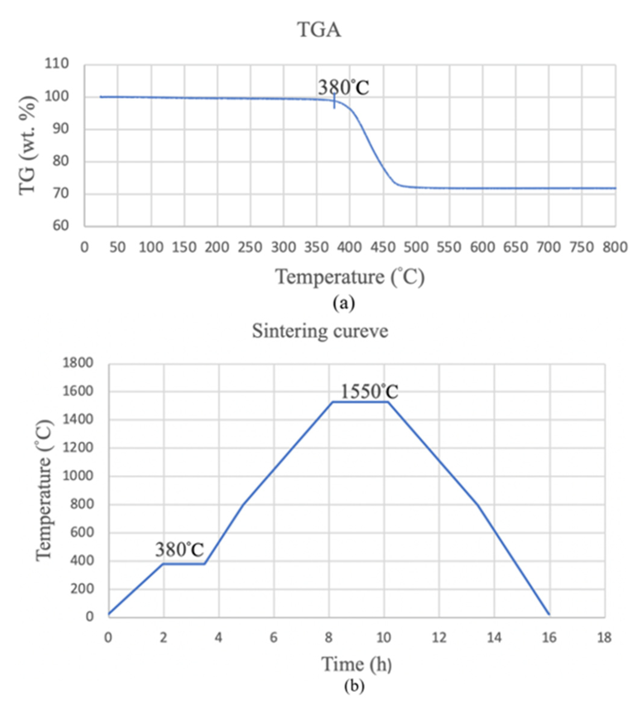
2.4.4. Thermogravimetric Analysis and Two-Stage Sintering
2.4.5. Shrinkage Measurement
2.5. Benchmark Fabrication
3. Results and Discussion
3.1. Development of the Submersion-Light Three-Dimensional Slurry Printer
3.2. Viscosity Measurement
3.3. Curing Results
3.4. Optimizing the Ascension Speed of the LE Box
3.5. Measurement of the Physical Properties
3.6. Measurement of the Shrinkage Ratio
3.7. Microstructure and Mechanical Properties
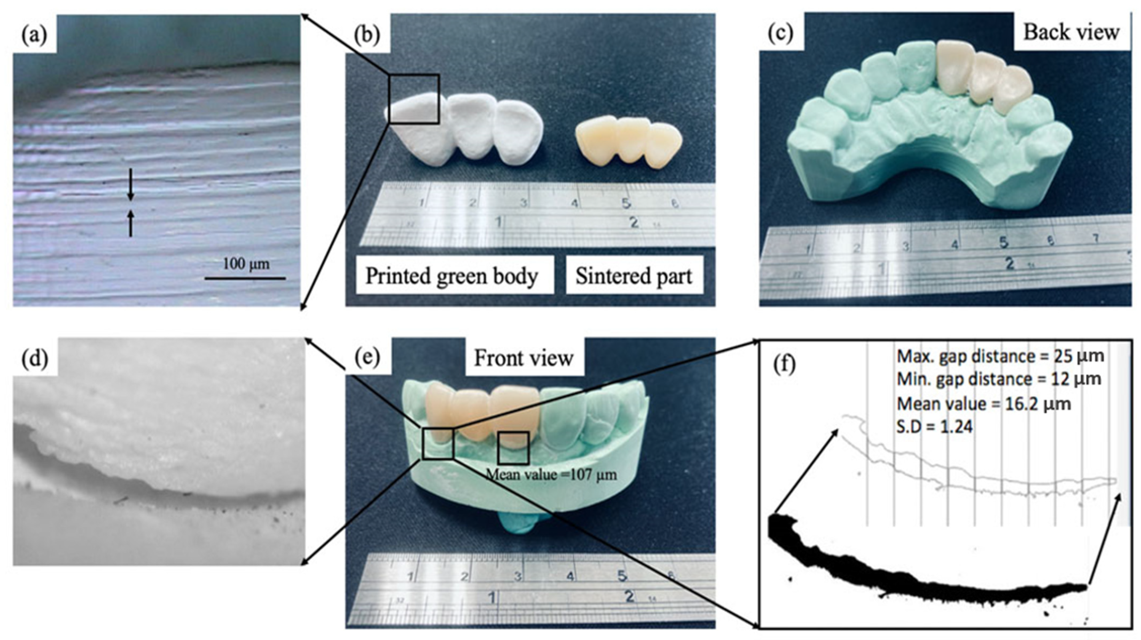
3.8. Benchmark Fabrication
4. Conclusions
Author Contributions
Funding
Institutional Review Board Statement
Informed Consent Statement
Data Availability Statement
Acknowledgments
Conflicts of Interest
References
- Chen, Z.; Li, J.; Liu, C.; Liu, Y.; Zhu, J.; Lao, C. Preparation of high solid loading and low viscosity ceramic slurries for photopolymerization-based 3D printing. Ceram. Int. 2019, 45, 11549–11557. [Google Scholar] [CrossRef]
- Santoliquido, O.; Paolo, C.; Alberto, O. Additive Manufacturing of ceramic components by Digital Light Processing: A comparison between the “bottom-up” and the “top-down” approaches. J. Eur. Ceram. Soc. 2019, 39, 2140–2148. [Google Scholar] [CrossRef]
- Santoliquido, O.; Camerota, F.; Rosa, A.; Ortona, A. A Novel Device to Simply 3D Print Bulk Green Ceramic Components by Stereolithography Employing Viscous Slurries. Open Ceram. 2021, 5, 100089. [Google Scholar] [CrossRef]
- Wang, J.-C.; Dommati, H. Fabrication of zirconia ceramic parts by using solvent-based slurry stereolithography and sintering. Int. J. Adv. Manuf. Technol. 2018, 98, 1537–1546. [Google Scholar] [CrossRef]
- Komissarenko, D.A.; Sokolov, P.S.; Evstigneeva, A.D.; Shmeleva, I.A.; Dosovitsky, A.E. Rheological and curing behavior of acrylate-based suspensions for the DLP 3D printing of complex zirconia parts. Materials 2018, 11, 2350. [Google Scholar] [CrossRef] [PubMed] [Green Version]
- Lian, Q.; Wu, X.; Li, D.; He, X.; Meng, J.; Liu, X.; Jin, Z. Accurate printing of a zirconia molar crown bridge using three-part auxiliary supports and ceramic mask projection stereolithography. Ceram. Int. 2019, 45, 18814–18822. [Google Scholar] [CrossRef]
- Guo, J.; Zeng, Y.; Li, P.; Chen, J. Fine lattice structural titanium dioxide ceramic produced by DLP 3D printing. Ceram. Int. 2019, 45, 23007–23012. [Google Scholar] [CrossRef]
- Konstantinou, G.; Kakkava, E.; Hagelüken, L.; Sasikumar, P.V.W.; Wang, J.; Makowska, M.G.; Blugan, G.; Nianias, N.; Marone, F.; Van Swygenhoven, H.; et al. Additive micro-manufacturing of crack-free PDCs by two-photon polymerization of a single, low-shrinkage preceramic resin. Addit. Manuf. 2020, 35, 101343. [Google Scholar] [CrossRef]
- Zakeri, S.; Vippola, M.; Levänen, E. A comprehensive review of the photopolymerization of ceramic resins used in stereolithography. Addit. Manuf. 2020, 35, 101177. [Google Scholar] [CrossRef]
- An, D.; Li, H.; Xie, Z.; Zhu, T.; Luo, X.; Shen, Z.; Ma, J. Additive manufacturing and characterization of complex Al2O3 parts based on a novel stereolithography method. Int. J. Appl. Ceram. Technol. 2017, 14, 836–844. [Google Scholar] [CrossRef]
- Corson, L.C.; Jackson, K.W.; Quinn, A.C.; Lu, H.; Tomonori, S.; Andrew, T. Nelson. Accuracy of stereolithography printed alumina with digital light processing. Open Ceram. 2021, 8, 100194. [Google Scholar]
- Lee, S.-Y.; Jiang, C.-P. Development of a three-dimensional slurry printing system using dynamic mask projection for fabricating zirconia dental implants. Mater. Manuf. Process. 2015, 30, 1498–1504. [Google Scholar] [CrossRef]
- Hsu, H.-J.; Lee, S.-Y.; Jiang, C.-P.; Lin, R. A comparison of the marginal fit and mechanical properties of a zirconia dental crown using CAM and 3DSP. Rapid Prototyp. J. 2019, 25, 1187–1197. [Google Scholar] [CrossRef]
- Zhang, J.; Huang, D.; Liu, S.; Dong, X.; Li, Y.; Zhang, H.; Yang, Z.; Su, Q.; Huang, W.; Zheng, W. Zirconia toughened hydroxyapatite biocomposite formed by a DLP 3D printing process for potential bone tissue engineering. Mater. Sci. Eng. C 2019, 105, 110054. [Google Scholar] [CrossRef] [PubMed]
- Gaddam, A.; Daniela, S.B.; Ana, S.N.; Bo, N.; José, M.F.F. Three-dimensional printing of zirconia scaffolds for load bearing applications: Study of the optimal fabrication conditions. J. Am. Ceram. Soc. 2021, 104, 4368–4380. [Google Scholar] [CrossRef]
- Cheng, Y.-C.; Jiang, C.-P.; Lin, D.-H. Finite element based optimization design for a one-piece zirconia ceramic dental implant under dynamic loading and fatigue life validation. Struct. Multidiscip. Optim. 2019, 59, 835–849. [Google Scholar] [CrossRef]
- Jiang, C.-P.; Hsu, H.-J.; Lee, S.-Y. Development of mask-less projection slurry stereolithography for the fabrication of zirconia dental coping. Int. J. Precis. Eng. Manuf. 2014, 15, 2413–2419. [Google Scholar] [CrossRef]
- He, R.; Liu, W.; Wu, Z.; An, D.; Huang, M.; Wu, H.; Jiang, Q.; Ji, X.; Wu, S.; Xie, Z. Fabrication of complex-shaped zirconia ceramic parts via a DLP-stereolithography-based 3D printing method. Ceram. Int. 2018, 44, 3412–3416. [Google Scholar] [CrossRef]
- Kim, J.-H.; Maeng, W.-Y.; Koh, Y.-H.; Kim, H.-E. Digital light processing of zirconia prostheses with high strength and translucency for dental applications. Ceram. Int. 2020, 46, 28211–28218. [Google Scholar] [CrossRef]
- Li, X.; Zhong, H.; Zhang, J.; Duan, Y.; Li, J.; Jiang, D. Fabrication of zirconia all-ceramic crown via DLP-based stereolithography. Int. J. Appl. Ceram. Technol. 2020, 17, 844–853. [Google Scholar] [CrossRef]
- Chen, F.; Zhu, H.; Wu, J.-M.; Chen, S.; Cheng, L.-J.; Shi, Y.-S.; Mo, Y.-C.; Li, C.-H.; Xiao, J. Preparation and biological evaluation of ZrO2 all-ceramic teeth by DLP technology. Ceram. Int. 2020, 46, 11268–11274. [Google Scholar] [CrossRef]
- Pagac, M.; Hajnys, J.; Ma, Q.-P.; Jancar, L.; Jansa, J.; Stefek, P.; Mesicek, J. A Review of Vat Photopolymerization Technology: Materials, Applications, Challenges, and Future Trends of 3D Printing. Polymers 2021, 13, 598. [Google Scholar] [CrossRef]
- Huang, Y.-M.; Jiang, C.-P. On-line force monitoring of platform ascending rapid prototyping system. J. Mater. Process. Technol. 2005, 159, 257–264. [Google Scholar] [CrossRef]
- Norbert, C.; Dena, H.; Andrea, M. Zirconia dental implants: Where are we now, and where are we heading? Periodontology 2000 2016, 73, 241–258. [Google Scholar]
- Sun, Z.; Wu, L.; Zhao, J.; Zheng, Y. Aesthetic restoration of anterior teeth with different coloured substrates using digital monolithic zirconia crowns: Two case reports. Adv. Appl. Ceram. 2021, 120, 169–174. [Google Scholar] [CrossRef]
- Eichler, J.; Rödel, J.; Eisele, U.; Hoffman, M. Effect of grain size on mechanical properties of submicrometer 3Y-TZP: Fracture strength and hydrothermal degradation. J. Am. Ceram. Soc. 2007, 90, 2830–2836. [Google Scholar] [CrossRef]
- Trunec, M. Effect of grain size on mechanical properties of 3Y-TZP ceramics. Ceram.-Silikáty 2008, 52, 165–171. [Google Scholar]
- Kim, M.-J.; Choi, Y.-J.; Kim, S.-K.; Heo, S.-J.; Koak, J.-Y. Marginal Accuracy and Internal Fit of 3-D Printing Laser-Sintered Co-Cr Alloy Copings. Materials 2017, 10, 93. [Google Scholar] [CrossRef] [PubMed] [Green Version]
- Song, D.-B.; Han, M.-S.; Kim, S.-C.; Ahn, J.; Im, Y.-W.; Lee, H.-H. Influence of Sequential CAD/CAM Milling on the Fitting Accuracy of Titanium Three-Unit Fixed Dental Prostheses. Materials 2021, 14, 1401. [Google Scholar] [CrossRef] [PubMed]
- Kokubo, Y.; Tsumita, M.; Kano, T.; Sakurai, S.; Fukushima, S. Clinical marginal and internal gaps of zirconia all-ceramic crowns. J. Prosthodont. Res. 2011, 55, 40–43. [Google Scholar] [CrossRef] [PubMed] [Green Version]
- Grenade, C.; Mainjot, A.; Vanheusden, A. Fit of single tooth zirconia copings: Comparison between various manufacturing processes. J. Prosthet. Dent. 2011, 105, 249–255. [Google Scholar] [CrossRef]
- Hsu, H.J.; Lee, S.Y.; Chang, S.L.; Lo, C.H.; Lin, Y.M. Shrinkage prediction using finite element analysis and experimental validation using three-dimension slurry printing system. Int. J. Adv. Manuf. Technol. 2017, 91, 1289–1296. [Google Scholar] [CrossRef]
- Öztürk, C.; Çelik, E. Influence of heating rate on the flexural strength of monolithic zirconia. J. Adv. Prosthodont. 2019, 11, 202–208. [Google Scholar] [CrossRef] [PubMed] [Green Version]


Publisher’s Note: MDPI stays neutral with regard to jurisdictional claims in published maps and institutional affiliations. |
© 2021 by the authors. Licensee MDPI, Basel, Switzerland. This article is an open access article distributed under the terms and conditions of the Creative Commons Attribution (CC BY) license (https://creativecommons.org/licenses/by/4.0/).
Share and Cite
Jiang, C.-P.; Hentihu, M.F.R.; Cheng, Y.-C.; Lei, T.-Y.; Lin, R.; Chen, Z. Development of 3D Slurry Printing Technology with Submersion-Light Apparatus in Dental Application. Materials 2021, 14, 7873. https://doi.org/10.3390/ma14247873
Jiang C-P, Hentihu MFR, Cheng Y-C, Lei T-Y, Lin R, Chen Z. Development of 3D Slurry Printing Technology with Submersion-Light Apparatus in Dental Application. Materials. 2021; 14(24):7873. https://doi.org/10.3390/ma14247873
Chicago/Turabian StyleJiang, Cho-Pei, M. Fahrur Rozy Hentihu, Yung-Chang Cheng, Tzu-Yi Lei, Richard Lin, and Zhangwei Chen. 2021. "Development of 3D Slurry Printing Technology with Submersion-Light Apparatus in Dental Application" Materials 14, no. 24: 7873. https://doi.org/10.3390/ma14247873