
The Effect of Graphite Additives on Magnetization, Resistivity and Electrical Conductivity of Magnetorheological Plastomer

 , , ,
, , ,  , , , and
Abstract
:1. Introduction
2. Experimental
2.1. Raw Materials
2.2. Fabrication of Samples
2.3. Experimental Setup and Measurements
2.4. Characterization Method
3. Results and Discussion
3.1. ESEM Characterization
3.2. Magnetic Properties
3.3. Resistivity Properties
3.4. The Effect of Frequency on MRP and Gr–MRP
4. Conclusions
- (1)
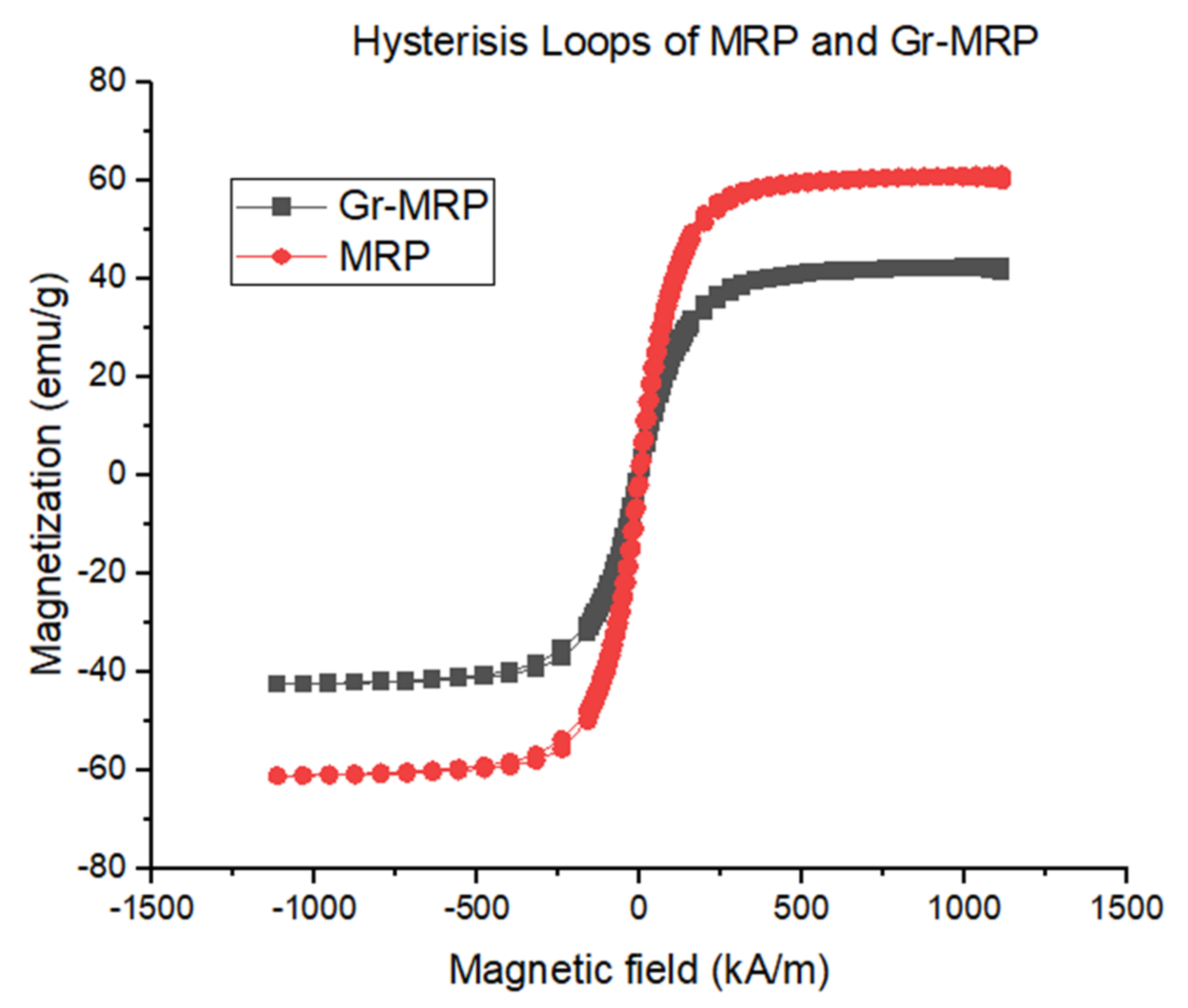
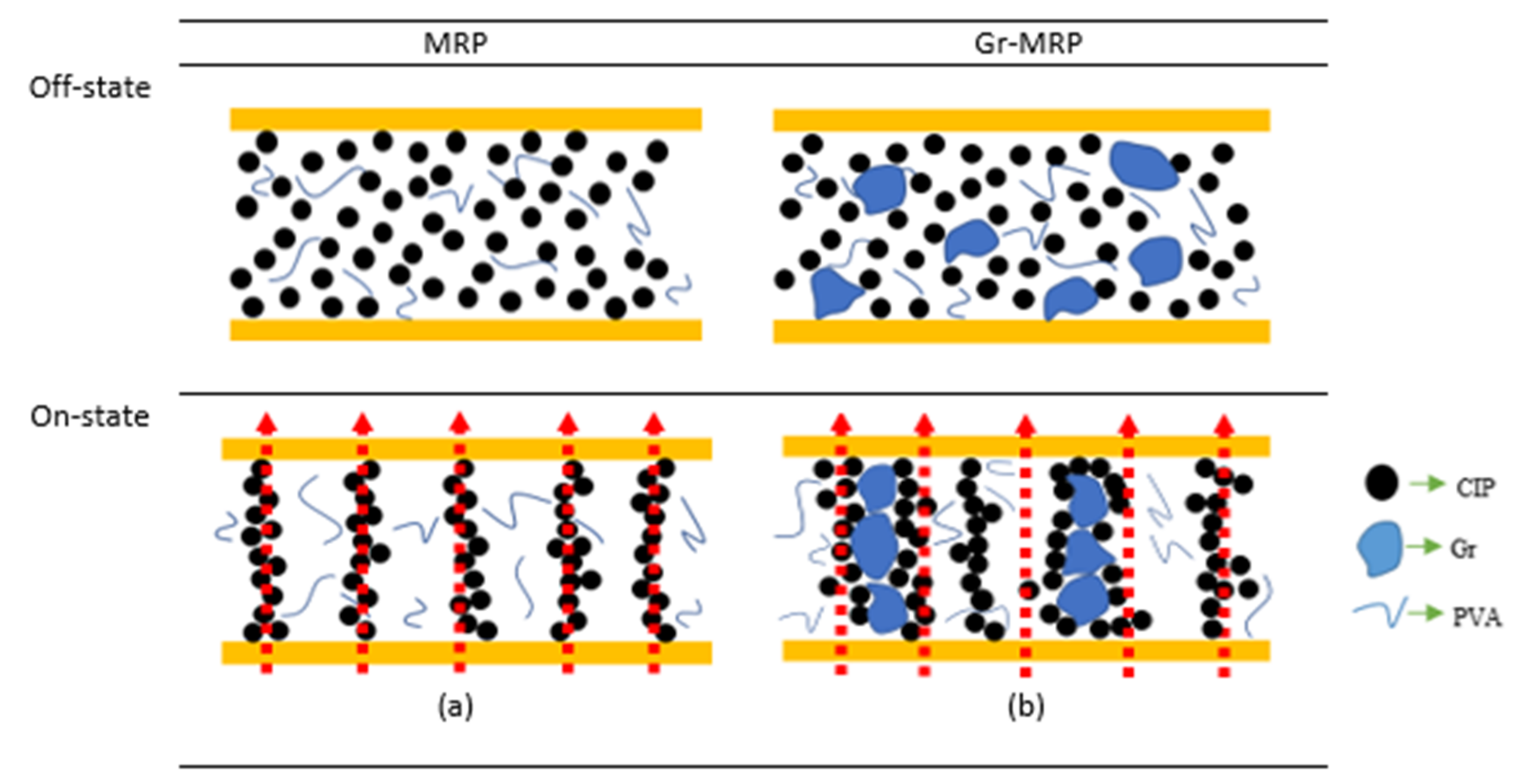
- The Gr–MRPs were fabricated using 6 wt.% to 10 wt.% Gr containing a DMSO/water ratio of 80:20 by weight. The magnetic properties of all samples were experimentally investigated. The results showed that the Gr–MRP sample had a higher Ms of 61.15 emu/g compared to the MRP sample (42.45 emu/g). The Ms of Gr–MRP dropped by 45% in comparison to the MRP sample, due to the Gr additive, which may hinder and obstruct the movement of CIPs. Thus, the interparticle interactions resulted in a smaller value of Ms.
- (2)
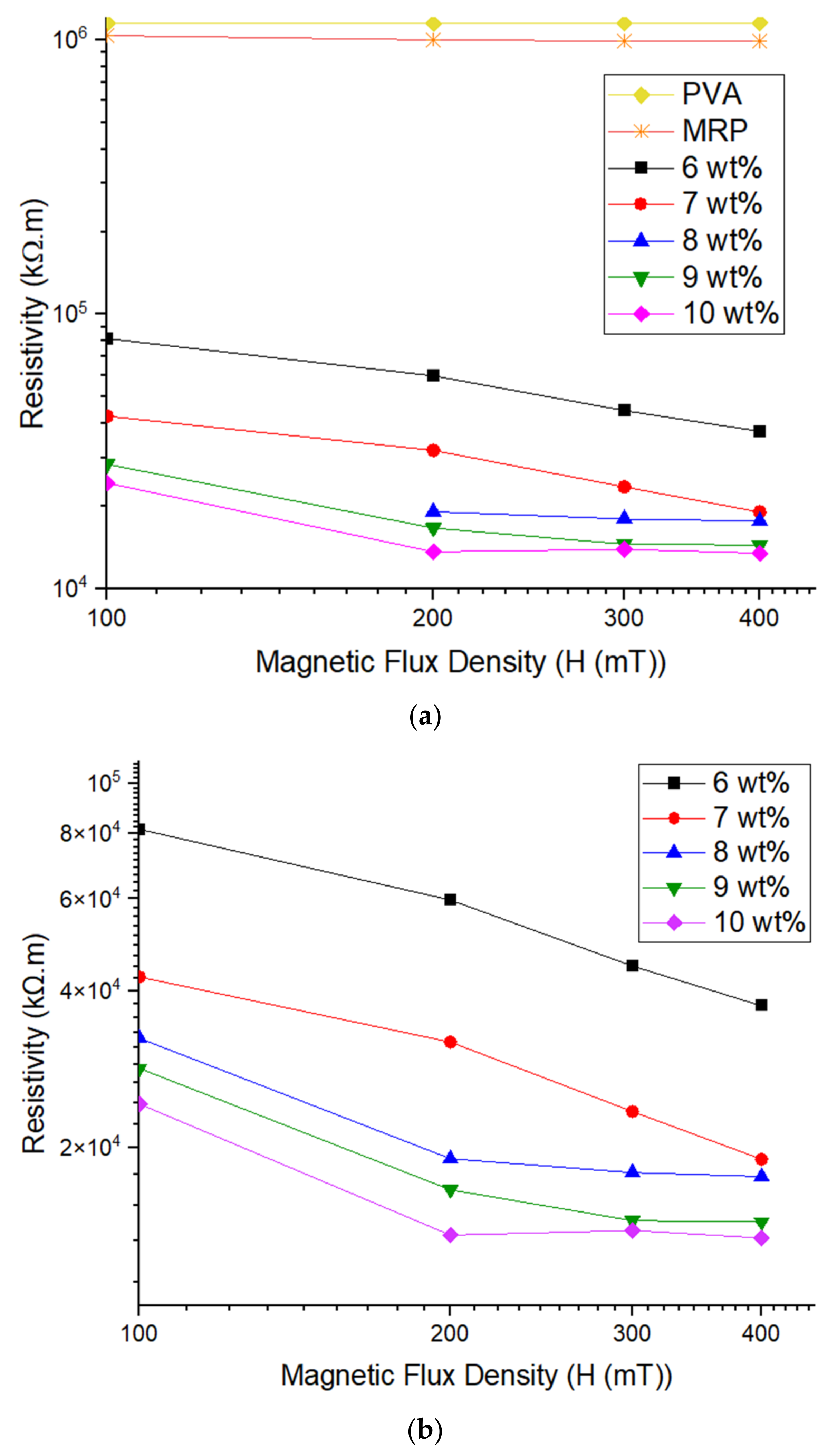
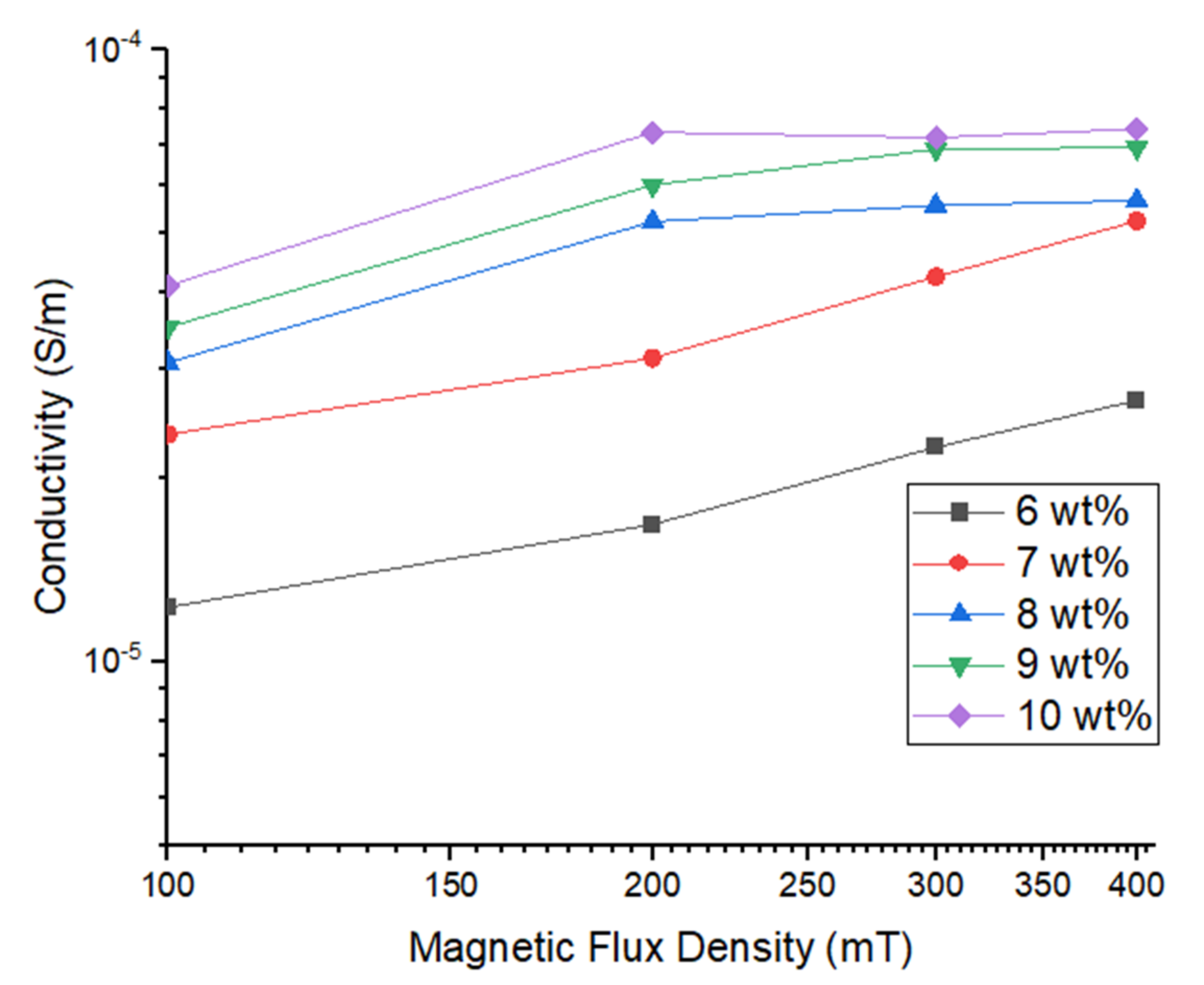
- The resistivities of the Gr–MRP samples decreased with increasing magnetic flux density. The higher the Gr content, the lower resistivity value observed. The conductivity of 10 wt.% Gr–MRP was found to be the highest and was 178.06% higher than the Gr–MRP with 6 wt.% at a magnetic flux density of 400 mT. In MRP, Gr functioned as the conductive agent and contributed to the improvement of the continuous conducting network.
- (3)
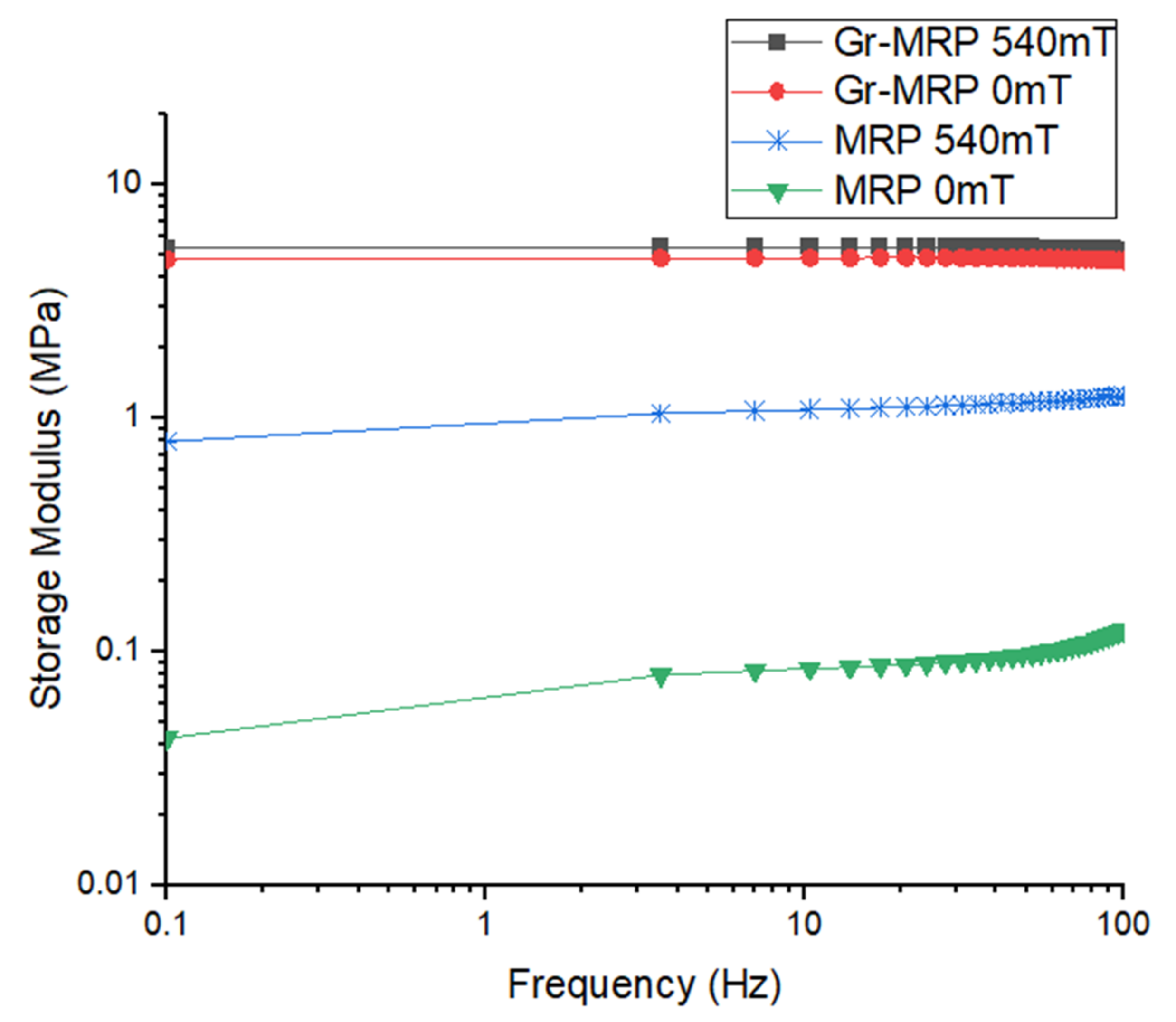
- The effective interfacial interaction between the additive and matrix increased the storage modulus of Gr–MRP, with a stronger interaction resulting in a higher storage modulus for Gr–MRP than for MRP only.
Author Contributions
Funding
Institutional Review Board Statement
Informed Consent Statement
Data Availability Statement
Acknowledgments
Conflicts of Interest
References
- Mohamad, N.; Mazlan, S.A.; Ubaidillah Choi, S.B.; Imaduddin, F.; Abdul Aziz, S.A. The field-dependent viscoelastic and transient responses of plate-like carbonyl iron particle based magnetorheological greases. J. Intell. Mater. Syst. Struct. 2019, 30, 788–797. [Google Scholar] [CrossRef]
- Djamal, M.; Ramli, R. Giant Magnetoresistance Sensors Based on Ferrite Material and Its Applications. In Magnetic Sensors—Development Trends and Applications; InTech: Bandung, Indonesia, 2017. [Google Scholar]
- Tian, T.F.; Li, W.H.; Deng, Y.M. Sensing capabilities of graphite based MR elastomers. Smart Mater. Struct. 2011, 20, 025022. [Google Scholar] [CrossRef]
- Liu, H.; Li, Q.; Zhang, S.; Yin, R.; Liu, X.; He, Y.; Dai, K.; Shan, C.; Guo, J.; Liu, C.; et al. Electrically conductive polymer composites for smart flexible strain sensors: A critical review. J. Mater. Chem. C 2018, 6, 12121–12141. [Google Scholar] [CrossRef]
- Zhang, P.; Chen, Y.; Li, Y.; Zhang, Y.; Zhang, J.; Huang, L. A Flexible Strain Sensor Based on the Porous Structure of a Carbon Black/Carbon Nanotube Conducting Network for Human Motion Detection. Sensors 2020, 20, 1154. [Google Scholar] [CrossRef] [Green Version]
- Lei, Z.; Wang, Q.; Sun, S.; Zhu, W.; Wu, P. A Bioinspired Mineral Hydrogel as a Self-Healable, Mechanically Adaptable Ionic Skin for Highly Sensitive Pressure Sensing. Adv. Mater. 2017, 29, 1700321. [Google Scholar] [CrossRef]
- Yun, J.; Lee, S.-S. Human Movement Detection and Identification Using Pyroelectric Infrared Sensors. Sensors 2014, 14, 8057–8081. [Google Scholar] [CrossRef]
- Xu, Y.; Gong, X.; Wan, Q.; Liu, T.; Xuan, S. Magneto-sensitive smart soft material and magnetorheological mechanism. Adv. Mech. 2015, 45, 461–495. [Google Scholar] [CrossRef]
- Imaduddin, F.; Nizam, M.; Mazlan, S.A. Response of a magnetorheological brake under inertial loads. Int. J. Electr. Eng. Inform. 2015, 7, 308–322. [Google Scholar] [CrossRef]
- Aziz, S.A.; Mazlan, S.A.; Ismail, N.N.; Choi, S.B.; Yunus, N.A. An enhancement of mechanical and rheological properties of magnetorheological elastomer with multiwall carbon nanotubes. J. Intell. Mater. Syst. Struct. 2017, 28, 3127–3138. [Google Scholar] [CrossRef]
- Muhazeli, N.S.; Nordin, N.A.; Mazlan, S.A.; Rizuan, N.; Abdul Aziz, S.A.; Abd Fatah, A.Y.; Ibrahim, Z.; Ubaidillah, U.; Choi, S.B. Characterization of morphological and rheological properties of rigid magnetorheological foams via in situ fabrication method. J. Mater. Sci. 2019, 54, 13821–13833. [Google Scholar] [CrossRef]
- Mohamad, N.; Mazlan, S.A.; Choi, S.B.; Nordin, M.F. The Field-Dependent Rheological Properties of Magnetorheological Grease Based on Carbonyl-Iron-Particles. Smart Mater. Struct. 2016, 25. [Google Scholar] [CrossRef]
- An, H.-N.; Sun, B.; Picken, S.J.; Mendes, E. Long Time Response of Soft Magnetorheological Gels. J. Phys. Chem. B 2012, 116, 4702–4711. [Google Scholar] [CrossRef]
- Xu, J.; Wang, P.; Pang, H.; Wang, Y.; Wu, J.; Xuan, S.; Gong, X. The dynamic mechanical properties of magnetorheological plastomers under high strain rate. Compos. Sci. Technol. 2018, 159, 50–58. [Google Scholar] [CrossRef]
- Hu, W.; Wang, R.; Lu, Y.; Pei, Q. An elastomeric transparent composite electrode based on copper nanowires and polyurethane. J. Mater. Chem. C 2014, 2, 1298–1305. [Google Scholar] [CrossRef]
- Sayyar, S.; Murray, E.; Thompson, B.C.; Chung, J.; Officer, D.L.; Gambhir, S.; Spinks, G.M.; Wallace, G.G. Processable conducting graphene/chitosan hydrogels for tissue engineering. J. Mater. Chem. B 2015, 3, 481–490. [Google Scholar] [CrossRef] [Green Version]
- Hapipi, N.M.; Mazlan, S.A.; Ubaidillah, U.; Abdul Aziz, S.A.; Ahmad Khairi, M.H.; Nordin, N.A.; Nazmi, N. Solvent Dependence of the Rheological Properties in Hydrogel Magnetorheological Plastomer. Int. J. Mol. Sci. 2020, 21, 1793. [Google Scholar] [CrossRef] [Green Version]
- Ge, L.; Gong, X.; Wang, Y.; Xuan, S. The conductive three dimensional topological structure enhanced magnetorheological elastomer towards a strain sensor. Compos. Sci. Technol. 2016, 135, 92–99. [Google Scholar] [CrossRef]
- Wang, Y.; Xuan, S.; Dong, B.; Xu, F.; Gong, X. Stimuli dependent impedance of conductive magnetorheological elastomers. Smart Mater. Struct. 2016, 25, 025003. [Google Scholar] [CrossRef]
- Wang, Y.; Xuan, S.; Ge, L.; Wen, Q.; Gong, X. Conductive magnetorheological elastomer: Fatigue dependent impedance-mechanic coupling properties. Smart Mater. Struct. 2017, 26, 015004. [Google Scholar] [CrossRef]
- An, H.; Picken, S.J.; Mendes, E. Enhanced hardening of soft self-assembled copolymer gels under homogeneous magnetic fields. Soft Matter 2010, 6, 4497. [Google Scholar] [CrossRef]
- Li, T.F.T.W.H.; Du, G.A.H. Microstructure and magnetorheology of graphite-based MR elastomers. Rheol. Acta 2011, 50, 825–836. [Google Scholar] [CrossRef]
- Yu, M.; Yang, P.; Fu, J.; Liu, S.; Choi, S. Sensors and Actuators A: Physical A theoretical model for the field-dependent conductivity of magneto-rheological gels and experimental verification. Sens. Actuators A Phys. 2016, 245, 127–134. [Google Scholar] [CrossRef]
- Martinez, F.; Obieta, G.; Uribe, I.; Sikora, T.; Ochoteco, E. Polymer-Based Self-Standing Flexible Strain Sensor. J. Sens. 2010, 2010, 1–5. [Google Scholar] [CrossRef]
- Sarfraz, M. Upgrading Electrical, Mechanical, and Chemical Properties of CNTs/Polybond® Nanocomposites: Pursuit of Electroconductive Structural Polymer Nanocomplexes. Int. J. Polym. Sci. 2016, 2016, 1–8. [Google Scholar] [CrossRef] [Green Version]
- Alarifi, I.M. Investigation the conductivity of carbon fiber composites focusing on measurement techniques under dynamic and static loads. J. Mater. Res. Technol. 2019, 8, 4863–4893. [Google Scholar] [CrossRef]
- Sengupta, R.; Bhattacharya, M.; Bandyopadhyay, S.; Bhowmick, A.K. A review on the mechanical and electrical properties of graphite and modified graphite reinforced polymer composites. Prog. Polym. Sci. 2011, 36, 638–670. [Google Scholar] [CrossRef]
- Fuchs, A.; Xin, M.; Gordaninejad, F.; Wang, X.; Hitchcock, G.H.; Gecol, H.; Evrensel, C.; Korol, G. Development and characterization of hydrocarbon polyol polyurethane and silicone magnetorheological polymeric gels. J. Appl. Polym. Sci. 2004, 92, 1176–1182. [Google Scholar] [CrossRef]
- Wilson, M.J.; Fuchs, A.; Gordaninejad, F. Development and characterization of magnetorheological polymer gels. J. Appl. Polym. Sci. 2002, 84, 2733–2742. [Google Scholar] [CrossRef]
- Hapipi, N.M.; Mazlan, S.A.; Ubaidillah, U.; Homma, K.; Aziz, S.A.A.; Nordin, N.A.; Bahiuddin, I.; Nazmi, N. The Rheological Studies on Poly(vinyl) Alcohol-Based Hydrogel Magnetorheological Plastomer. Polymers 2020, 12, 2332. [Google Scholar] [CrossRef] [PubMed]
- Alakanandana, A.; Subrahmanyam, A.R.; Siva Kumar, J. Structural and Electrical Conductivity studies of pure PVA and PVA doped with Succinic acid polymer electrolyte system. Mater. Today Proc. 2016, 3, 3680–3688. [Google Scholar] [CrossRef]
- Ahmad Khairi, M.H.; Mazlan, S.A.; Choi, S.B.; Abdul Aziz, S.A.; Mohamad, N.; Hapipi, N.M.; Nordin, N. Role of Additives in Enhancing the Rheological Properties of Magnetorheological Solids: A Review. Adv. Eng. Mater. 2019, 21, 1800696. [Google Scholar] [CrossRef]
- Zhang, Z.; Chen, X.; Wang, Z.; Heng, L.; Wang, S.; Tang, Z.; Zou, Y. Carbonyl iron/graphite microspheres with good impedance matching for ultra-broadband and highly efficient electromagnetic absorption. Opt. Mater. Express 2018, 8, 3319. [Google Scholar] [CrossRef]
- Siburian, R.; Sihotang, H.; Lumban Raja, S.; Supeno, M.; Simanjuntak, C. New Route to Synthesize of Graphene Nano Sheets. Orient. J. Chem. 2018, 34, 182–187. [Google Scholar] [CrossRef] [Green Version]
- Bica, I. Influence of the transverse magnetic field intensity upon the electric resistance of the magnetorheological elastomer containing graphite microparticles. Mater. Lett. 2009, 63, 2230–2232. [Google Scholar] [CrossRef]
- Huang, X.G.; Yan, Z.Y.; Liu, C.; Li, G.H.; Wang, J. Study on the resistance properties of magnetorheological elastomer. Mater. Res. Innov. 2015, 19, S5-924–S5-928. [Google Scholar] [CrossRef]
- Pang, H.; Xuan, S.; Liu, T.; Gong, X. Magnetic field dependent electro-conductivity of the graphite doped magnetorheological plastomers. Soft Matter 2015, 11, 6893–6902. [Google Scholar] [CrossRef]
- Ahmad Khairi, M.H.; Mazlan, S.A.; Ubaidillah Ku Ahmad, K.Z.; Choi, S.B.; Abdul Aziz, S.A.; Yunus, N.A. The field-dependent complex modulus of magnetorheological elastomers consisting of sucrose acetate isobutyrate ester. J. Intell. Mater. Syst. Struct. 2017, 28, 1993–2004. [Google Scholar] [CrossRef]
- Abd Rashid, R.Z.; Johari, N.; Mazlan, S.A.; Abdul Aziz, S.A.; Nordin, N.A.; Nazmi, N.; Aqida, S.N.; Johari, M.A.F. Effects of silica on mechanical and rheological properties of EPDM-based magnetorheological elastomers. Smart Mater. Struct. 2021, 30, 105033. [Google Scholar] [CrossRef]
- Ye, Y.; Li, X.; Zheng, D.; Qu, S.; Li, Y. Examination of Electrical Conduction of Carbonyl Iron Powder Compacts. Mater. Trans. 2015, 56, 696–702. [Google Scholar] [CrossRef] [Green Version]
- Mohd Nasir, N.A.; Nazmi, N.; Mohamad, N.; Ubaidillah, U.; Nordin, N.A.; Mazlan, S.A.; Abdul Aziz, S.A.; Shabdin, M.K.; Yunus, N.A. Rheological Performance of Magnetorheological Grease with Embedded Graphite Additives. Materials 2021, 14, 5091. [Google Scholar] [CrossRef]
- Shabdin, M.K.; Rahman, A.; Azizi, M.; Mazlan, S.A.; Hapipi, N.M.; Adiputra, D.; Aziz, A.; Aishah, S.; Bahiuddin, I.; Choi, S.B. Material Characterizations of Gr-Based Magnetorheological Elastomer for Possible Sensor Applications: Rheological and Resistivity Properties. Materials 2019, 12, 391. [Google Scholar] [CrossRef] [Green Version]
- Dueramae, I.; Pengdam, A.; Rimdusit, S. Highly filled graphite polybenzoxazine composites for an application as bipolar plates in fuel cells. J. Appl. Polym. Sci. 2013, 130, 3909–3918. [Google Scholar] [CrossRef]


| Type | Samples | CIP (wt.%) | PVA Matrix (wt.%) | CIP (wt.%) |
|---|---|---|---|---|
| MRP | 1 | 70 | 30 | 0 |
| Gr–MRP | 2 | 70 | 24 | 6 |
| - | 3 | 70 | 23 | 7 |
| - | 4 | 70 | 22 | 8 |
| - | 5 | 70 | 21 | 9 |
| - | 6 | 70 | 20 | 10 |
| Samples | Hc (kA/m) | Ms (emu/g) | Mr (emu/g) |
|---|---|---|---|
| MRP | 7.97 | 61.15 | 200.67 × 10⁻² |
| Gr–MRP | 7.97 | 42.45 | 116.58 × 10⁻² |
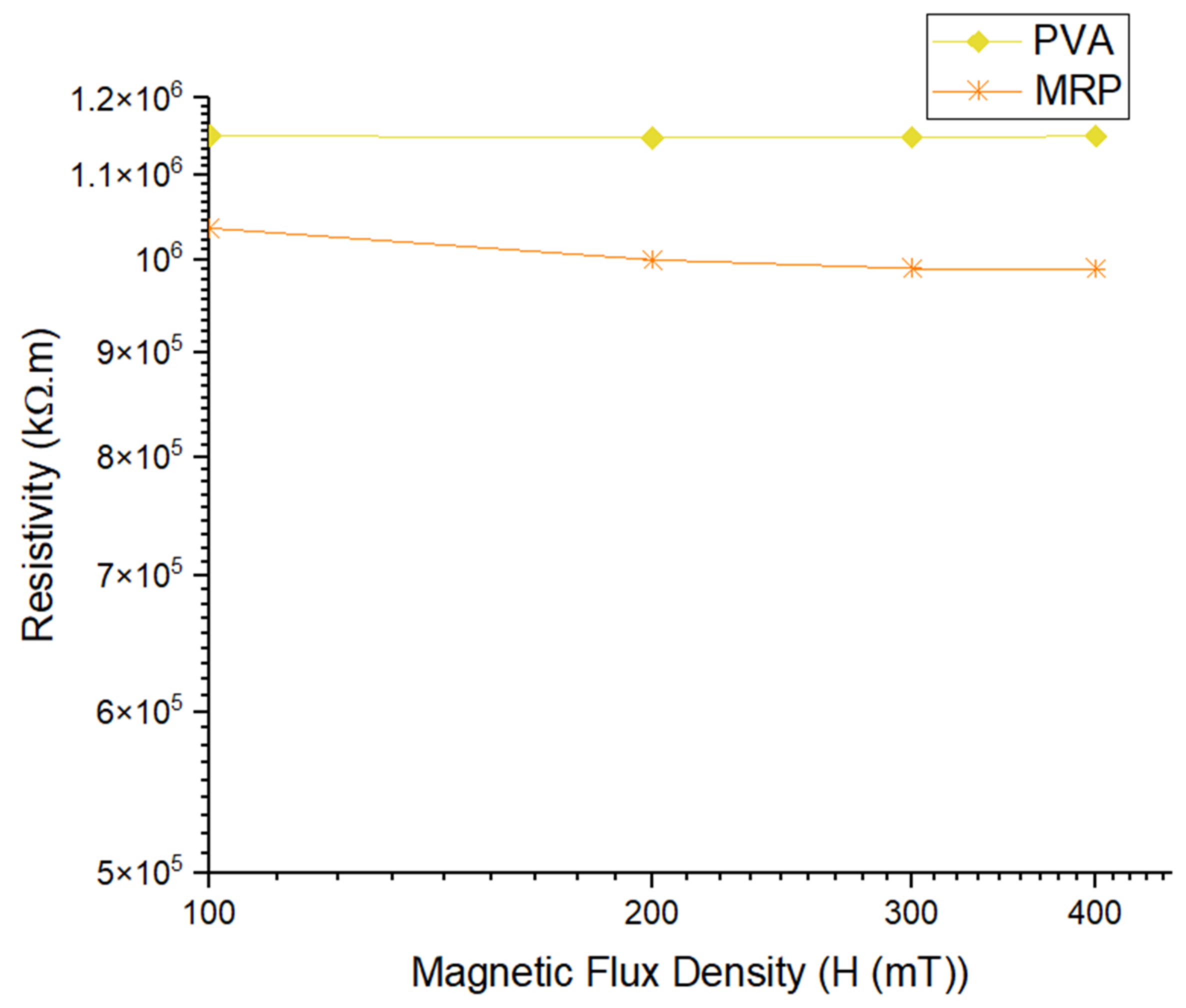
| Samples | Magnetic Flux Density, mT | |||||
|---|---|---|---|---|---|---|
| 0 | 100 | 200 | 300 | 400 | ||
| Resistivity (σ), kΩ·m | PVA | 1.15 × 10⁶ | 1.15 × 10⁶ | 1.15 × 10⁶ | 1.15 × 10⁶ | 1.15 × 10⁶ |
| MRP | 1.05 × 10⁶ | 1.04 × 10⁶ | 1.00 × 10⁶ | 9.90 × 10⁶ | 9.90 × 10⁶ | |
| Samples | Magnetic Flux Density, mT | |||||
|---|---|---|---|---|---|---|
| 0 | 100 | 200 | 300 | 400 | ||
| Resistivity (σ), kΩ·m | 2 | 9.90 × 10⁴ | 8.16 × 10⁴ | 5.97 × 10⁴ | 4.46 × 10⁴ | 3.74 × 10⁴ |
| 3 | 6.87 × 10⁴ | 4.25 × 10⁴ | 3.19 × 10⁴ | 2.35 × 10⁴ | 1.90 × 10⁴ | |
| 4 | 5.05 × 10⁴ | 3.25 × 10⁴ | 1.91 × 10⁴ | 1.80 × 10⁴ | 1.76 × 10⁴ | |
| 5 | 4.16 × 10⁴ | 2.84 × 10⁴ | 1.37 × 10⁴ | 1.36 × 10⁴ | 1.35 × 10⁴ | |
| 6 | 4.14 × 10⁴ | 2.43 × 10⁴ | 1.36 × 10⁴ | 1.36 × 10⁴ | 1.35 × 10⁴ | |
Publisher’s Note: MDPI stays neutral with regard to jurisdictional claims in published maps and institutional affiliations. |
© 2021 by the authors. Licensee MDPI, Basel, Switzerland. This article is an open access article distributed under the terms and conditions of the Creative Commons Attribution (CC BY) license (https://creativecommons.org/licenses/by/4.0/).
Share and Cite
Zaini, N.; Mohamad, N.; Mazlan, S.A.; Abdul Aziz, S.A.; Choi, S.-B.; Hapipi, N.M.; Nordin, N.A.; Nazmi, N.; Ubaidillah, U. The Effect of Graphite Additives on Magnetization, Resistivity and Electrical Conductivity of Magnetorheological Plastomer. Materials 2021, 14, 7484. https://doi.org/10.3390/ma14237484
Zaini N, Mohamad N, Mazlan SA, Abdul Aziz SA, Choi S-B, Hapipi NM, Nordin NA, Nazmi N, Ubaidillah U. The Effect of Graphite Additives on Magnetization, Resistivity and Electrical Conductivity of Magnetorheological Plastomer. Materials. 2021; 14(23):7484. https://doi.org/10.3390/ma14237484
Chicago/Turabian StyleZaini, Nursyafiqah, Norzilawati Mohamad, Saiful Amri Mazlan, Siti Aishah Abdul Aziz, Seung-Bok Choi, Norhiwani Mohd Hapipi, Nur Azmah Nordin, Nurhazimah Nazmi, and Ubaidillah Ubaidillah. 2021. "The Effect of Graphite Additives on Magnetization, Resistivity and Electrical Conductivity of Magnetorheological Plastomer" Materials 14, no. 23: 7484. https://doi.org/10.3390/ma14237484