
Study on Strength, Water Stability, Shrinkage, and Microstructure of CFB Slag Modified Cement Stabilized Clay

Abstract
:1. Introduction
2. Materials and Methods
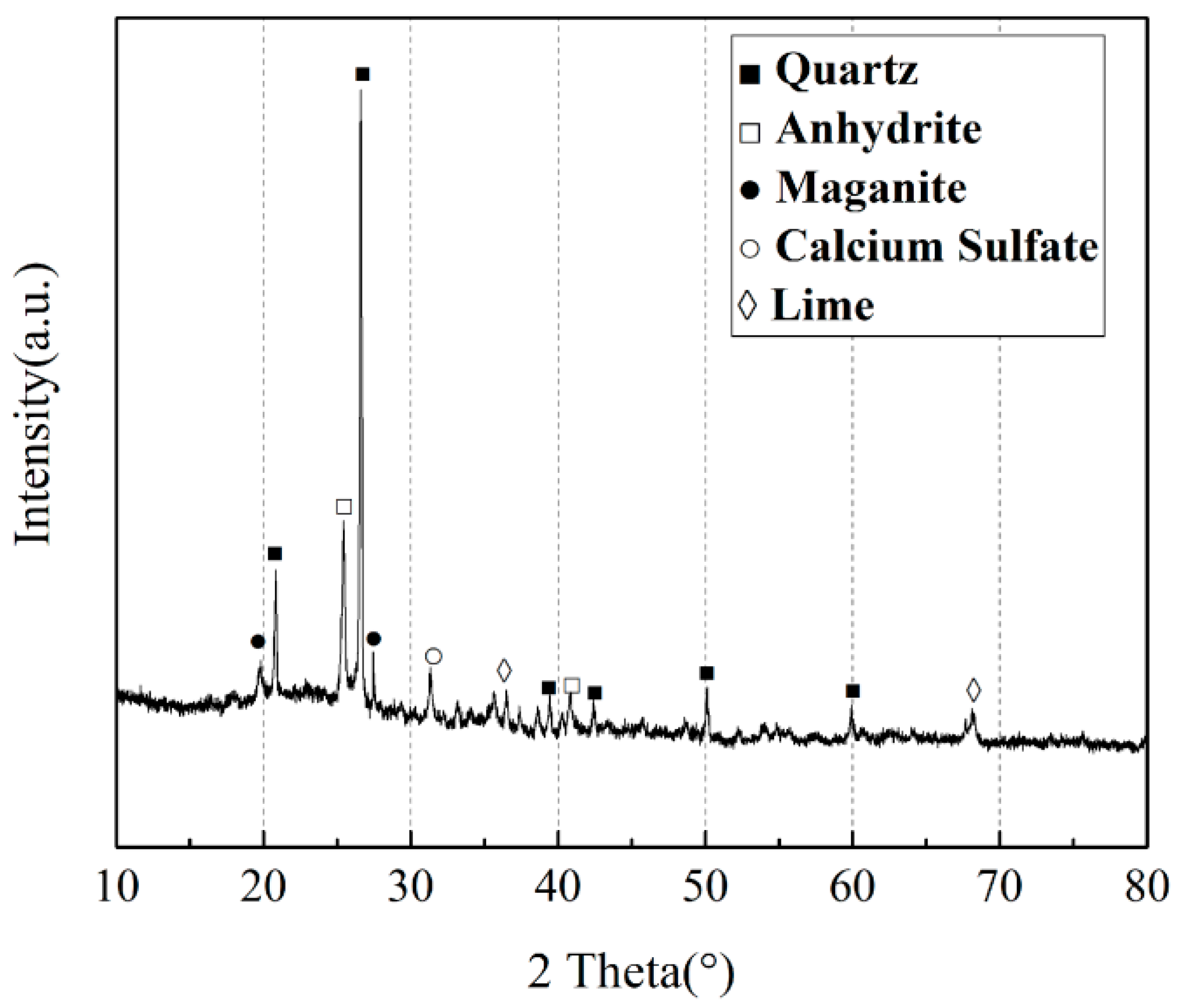
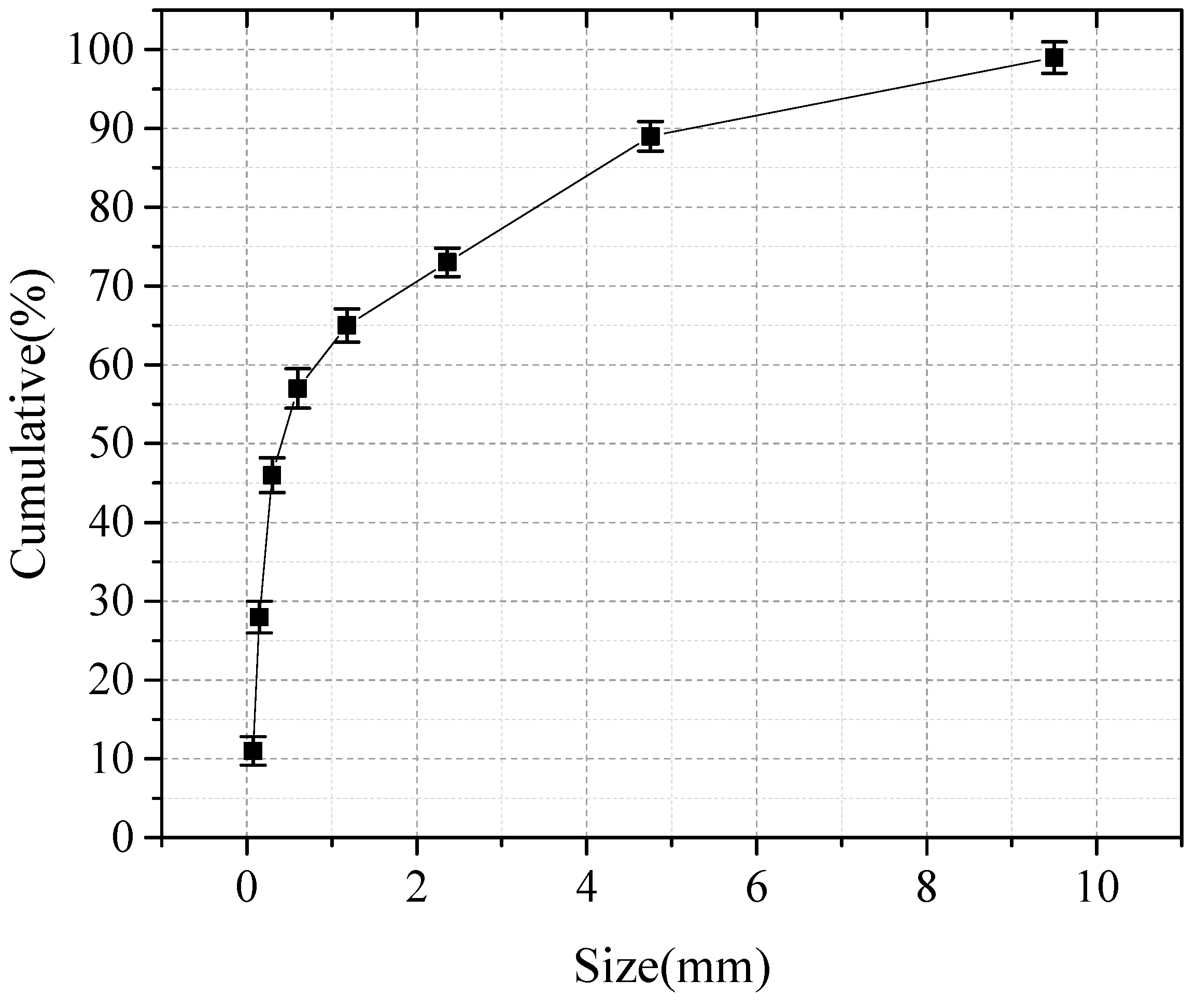
2.1. Materials
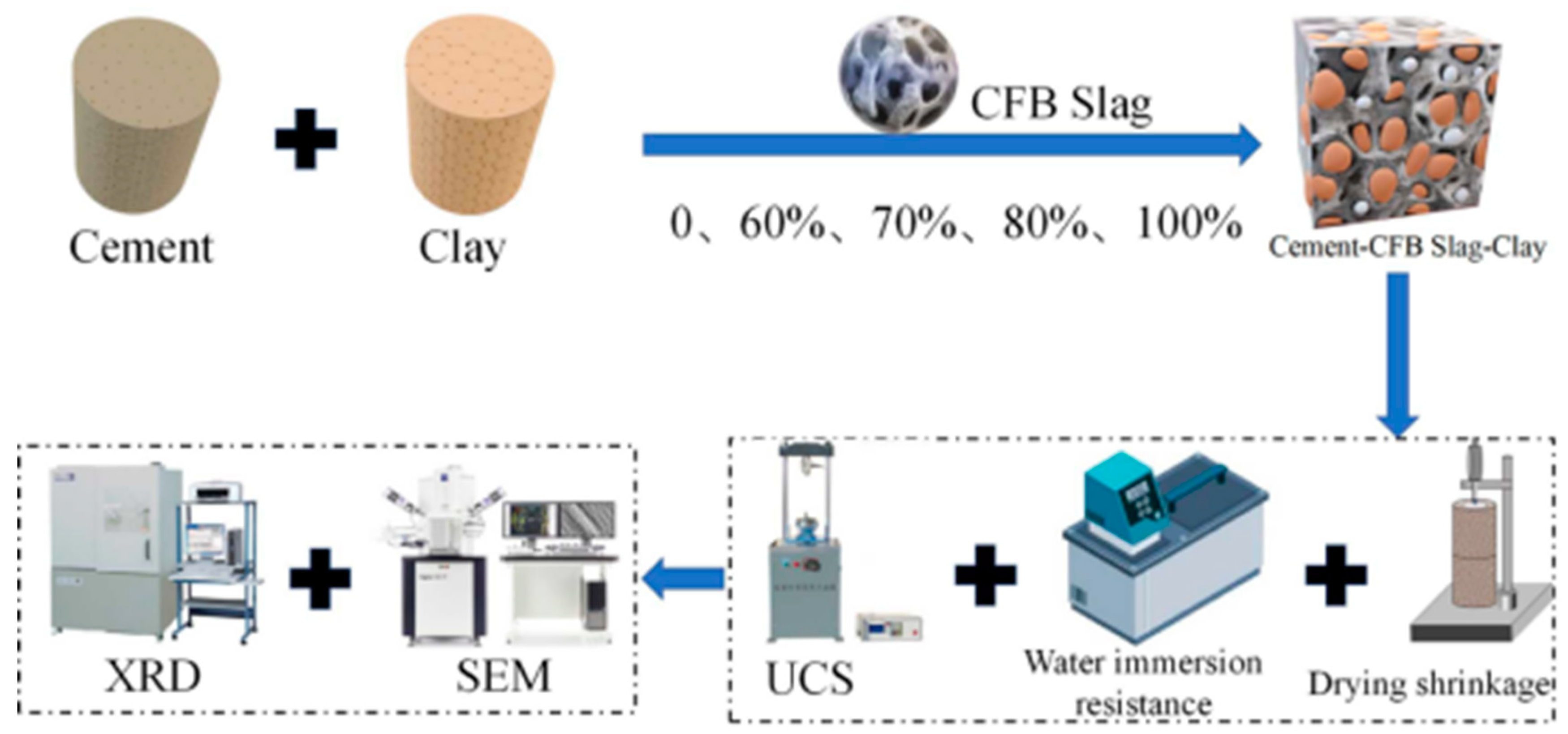
2.2. Methods
2.2.1. Strength Tests
2.2.2. Water Stability Tests
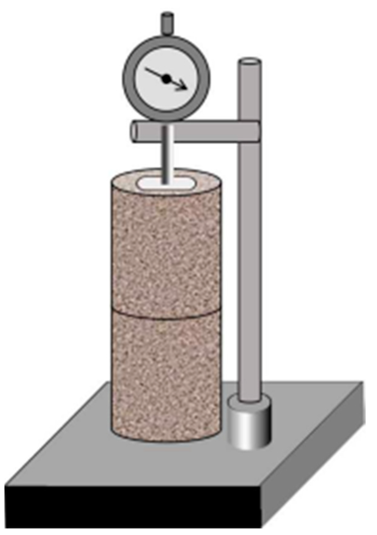
2.2.3. Shrinkage Tests
- —Linear shrinkage, accurate to 0.01%;
- —Original height of sample (mm);
- —Initial readings of dial indicator (mm);
- —Dial indicator readings of contraction process at some time (mm).
- —Water loss rate, accurate to 0.01%;
- —Sample quality of at during shrinkage some time (g);
- —The original quality of sample (g).
2.2.4. XRD and SEM
3. Results
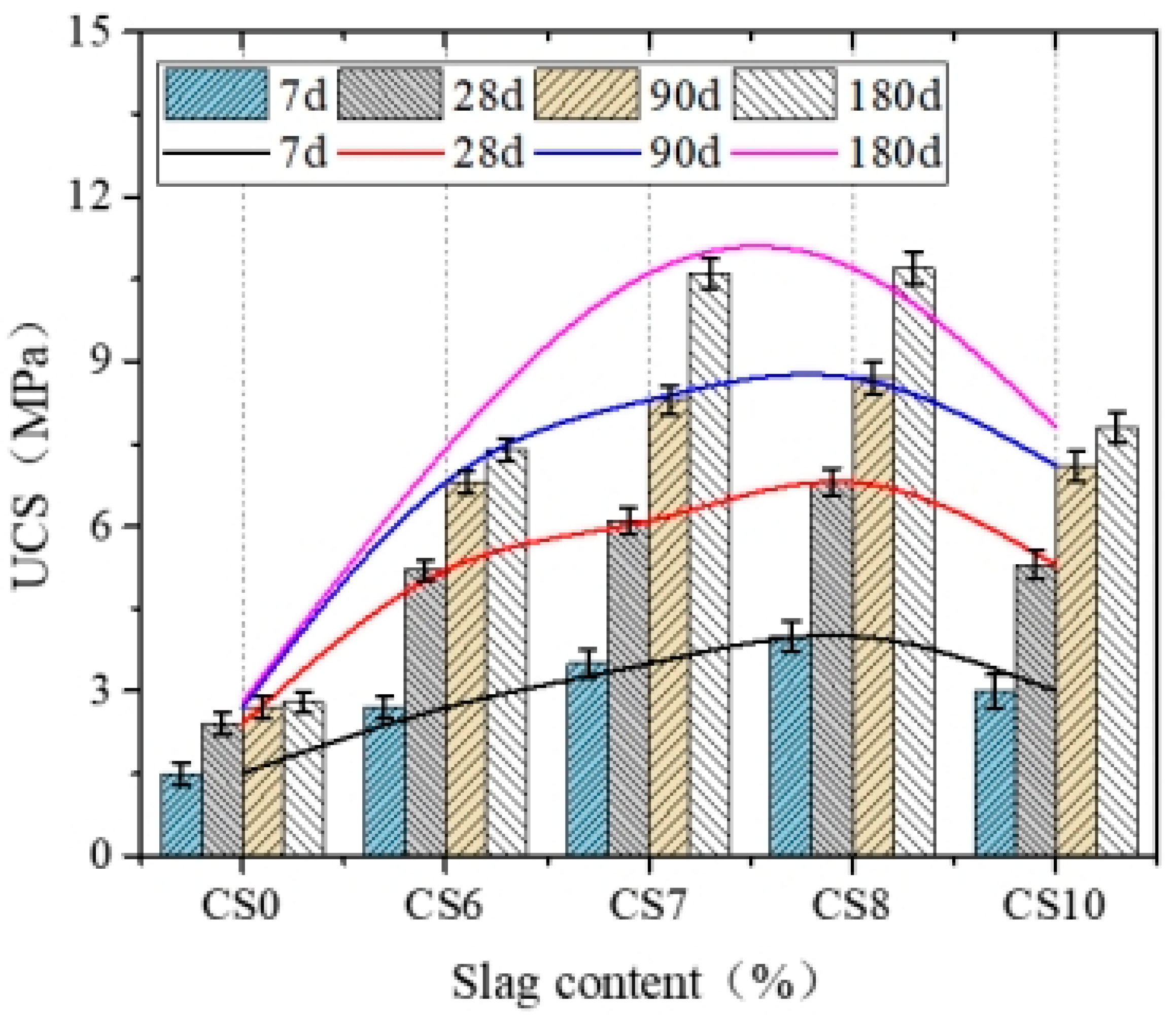
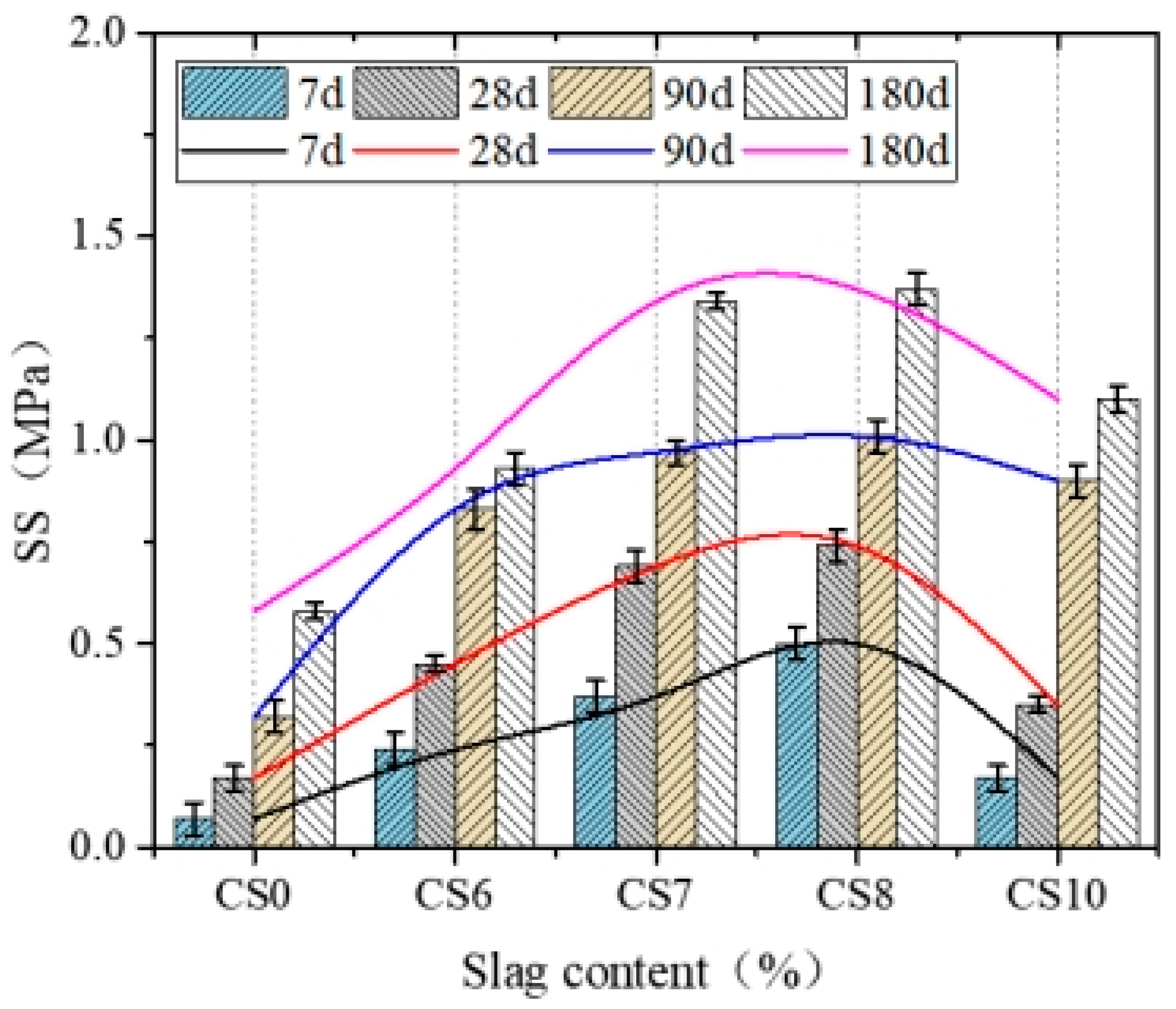
3.1. Mechanical Properties
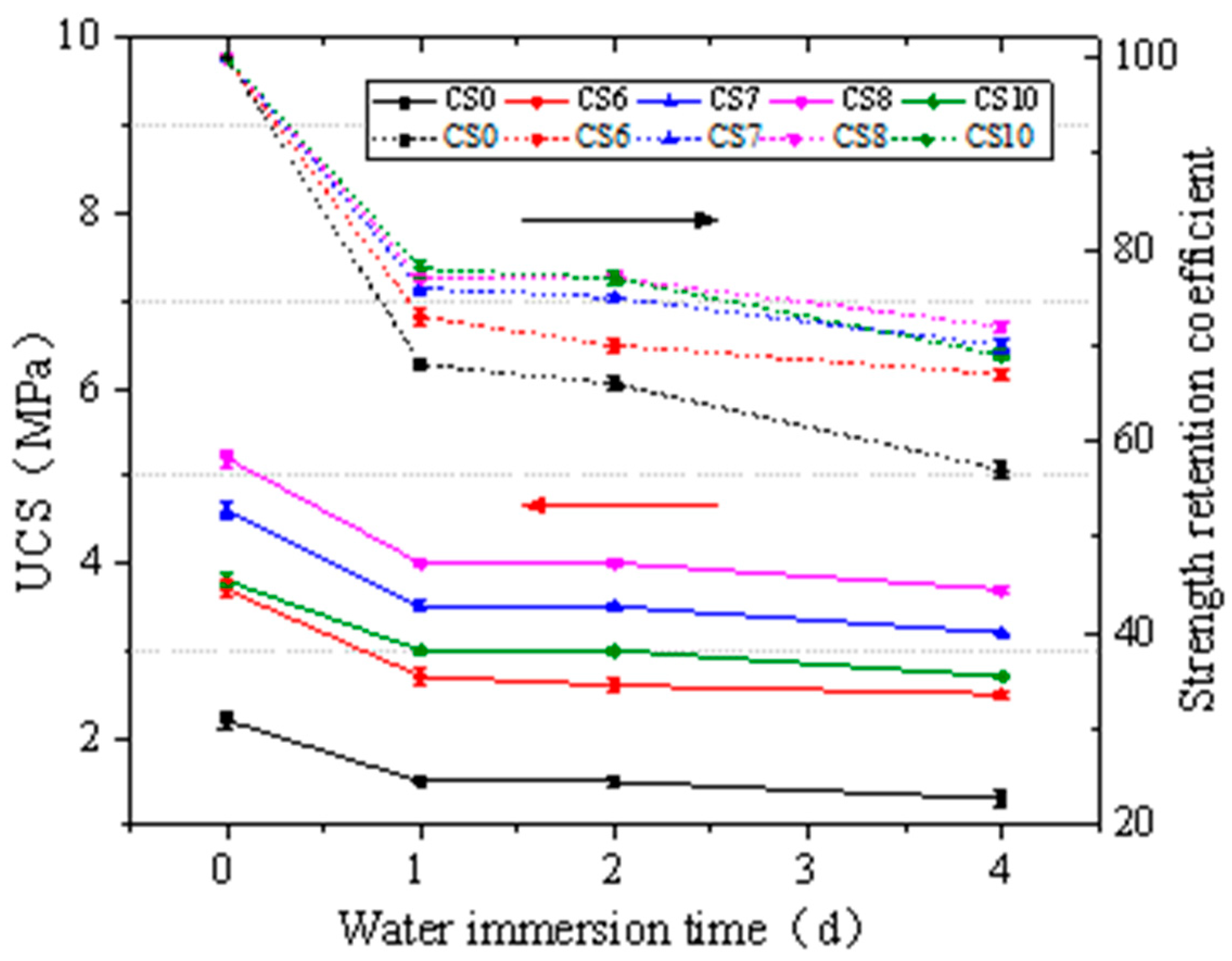
3.2. Resistance to Water Immersion
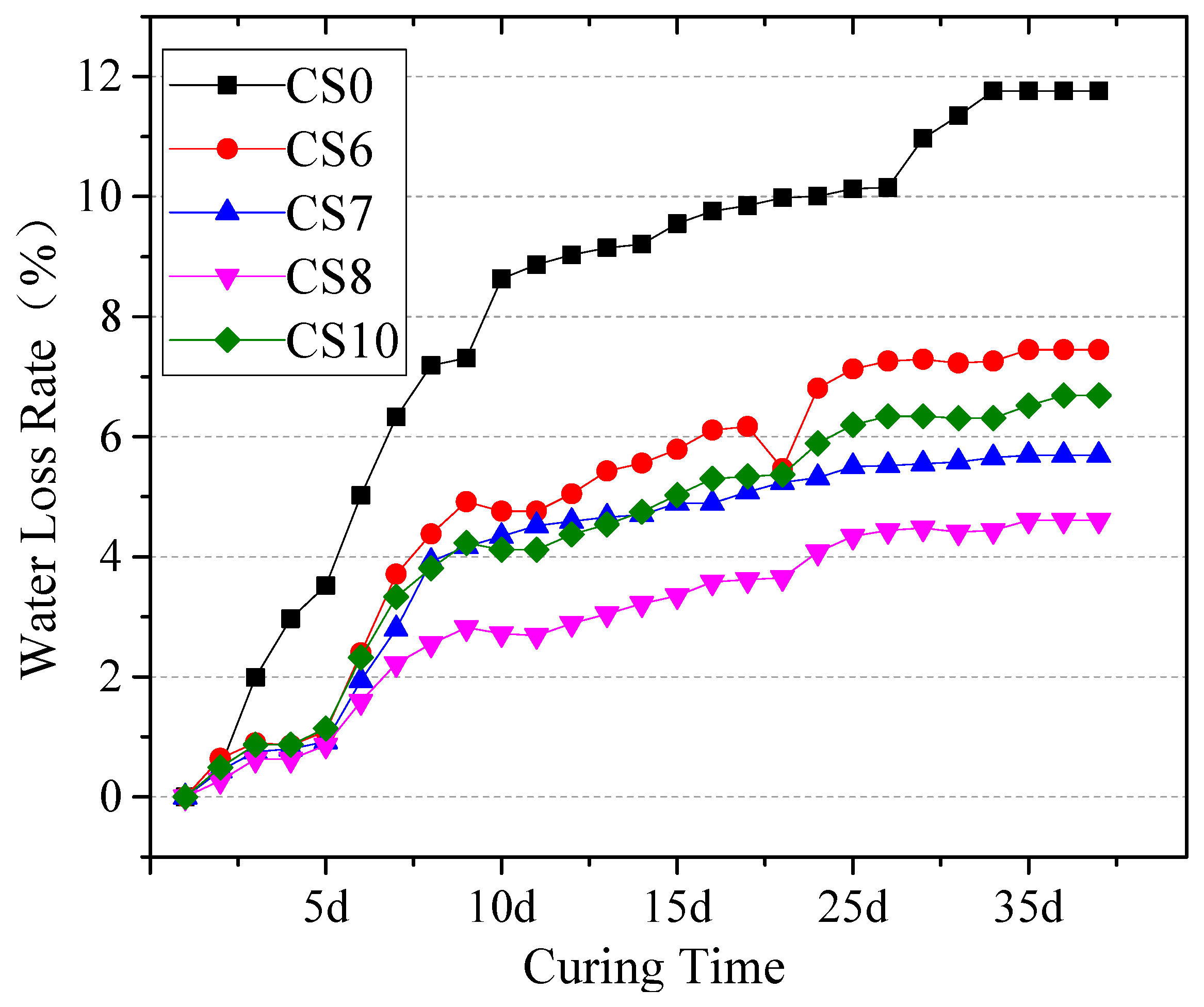
3.3. Shrinkage Properties
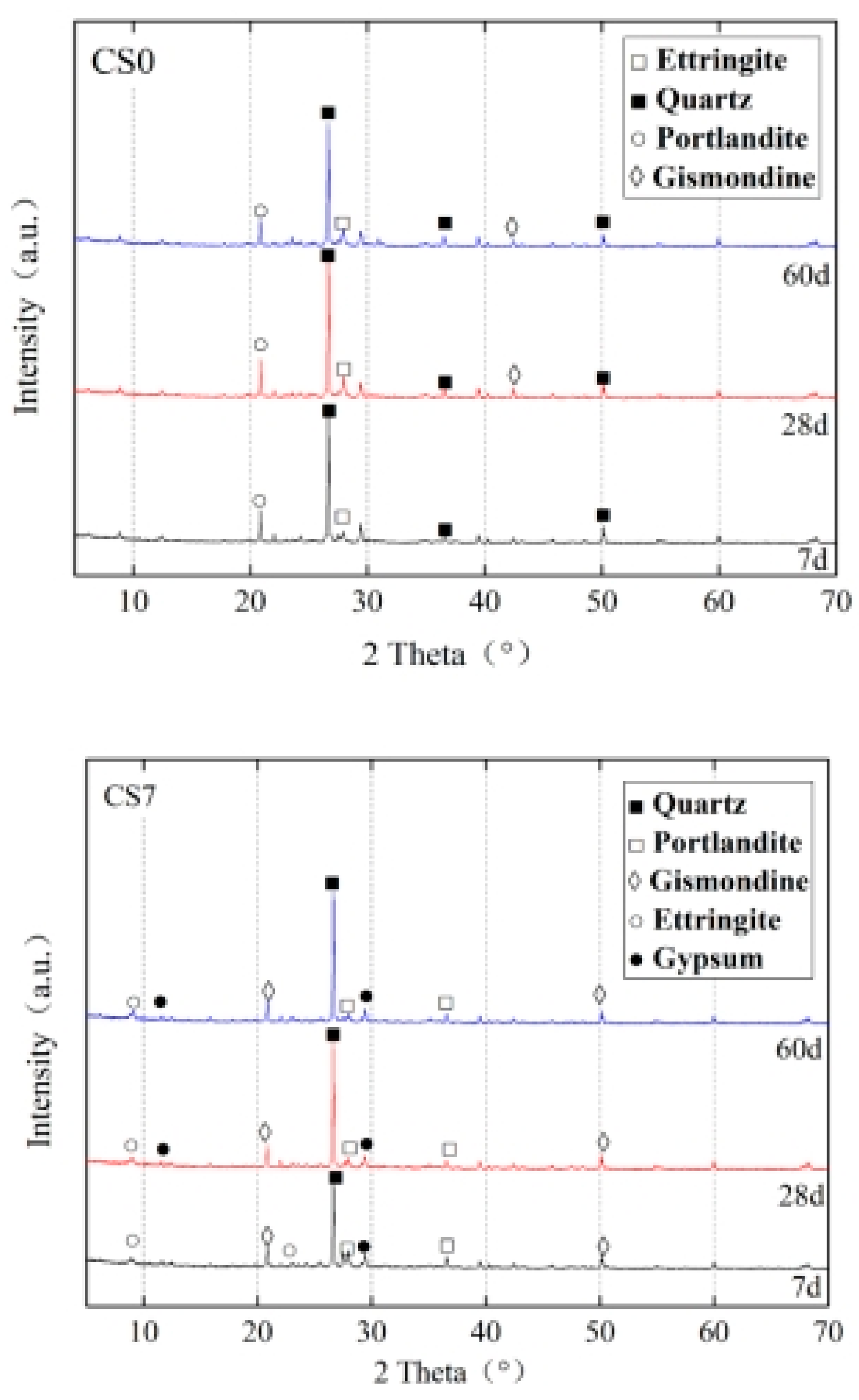
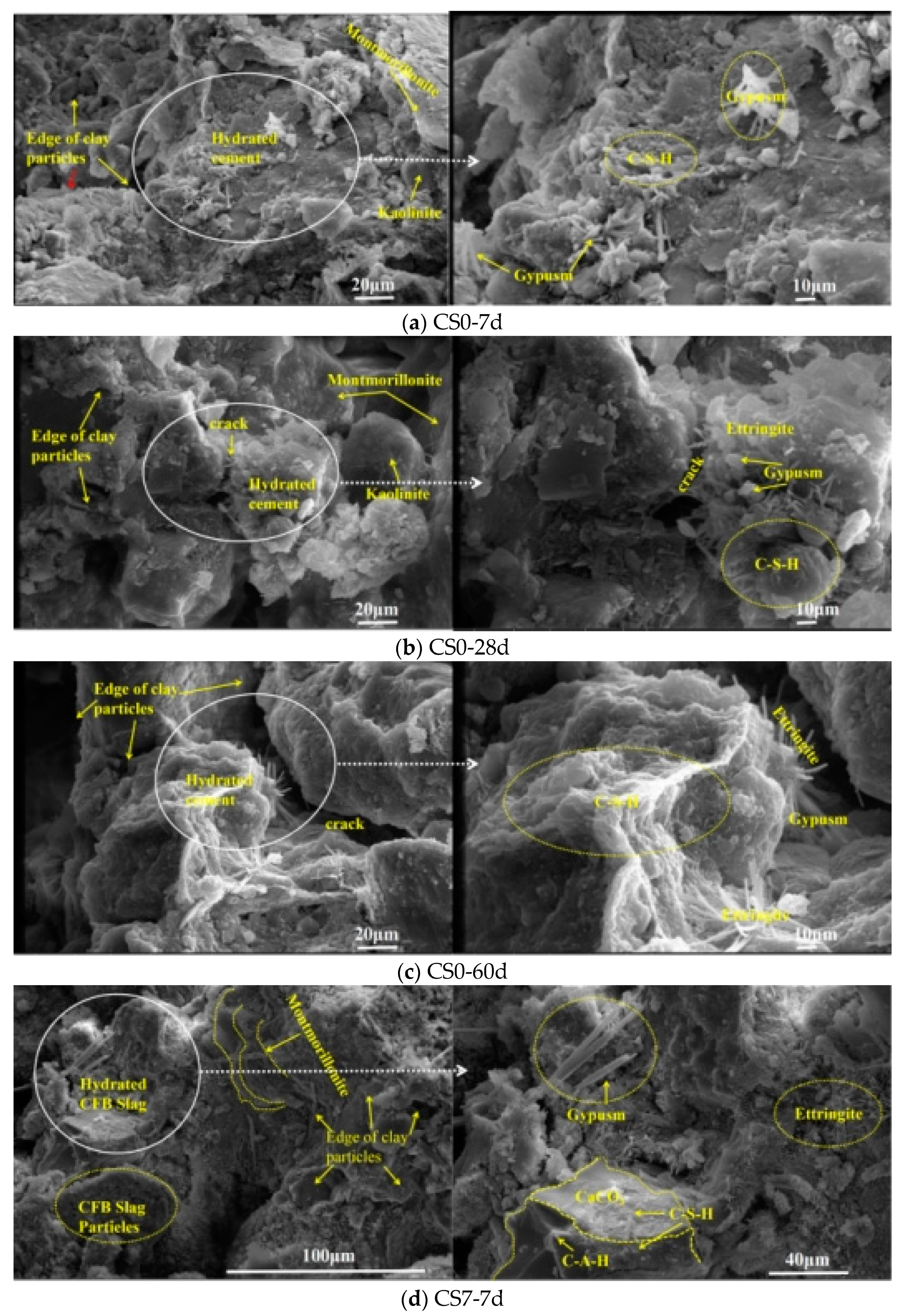
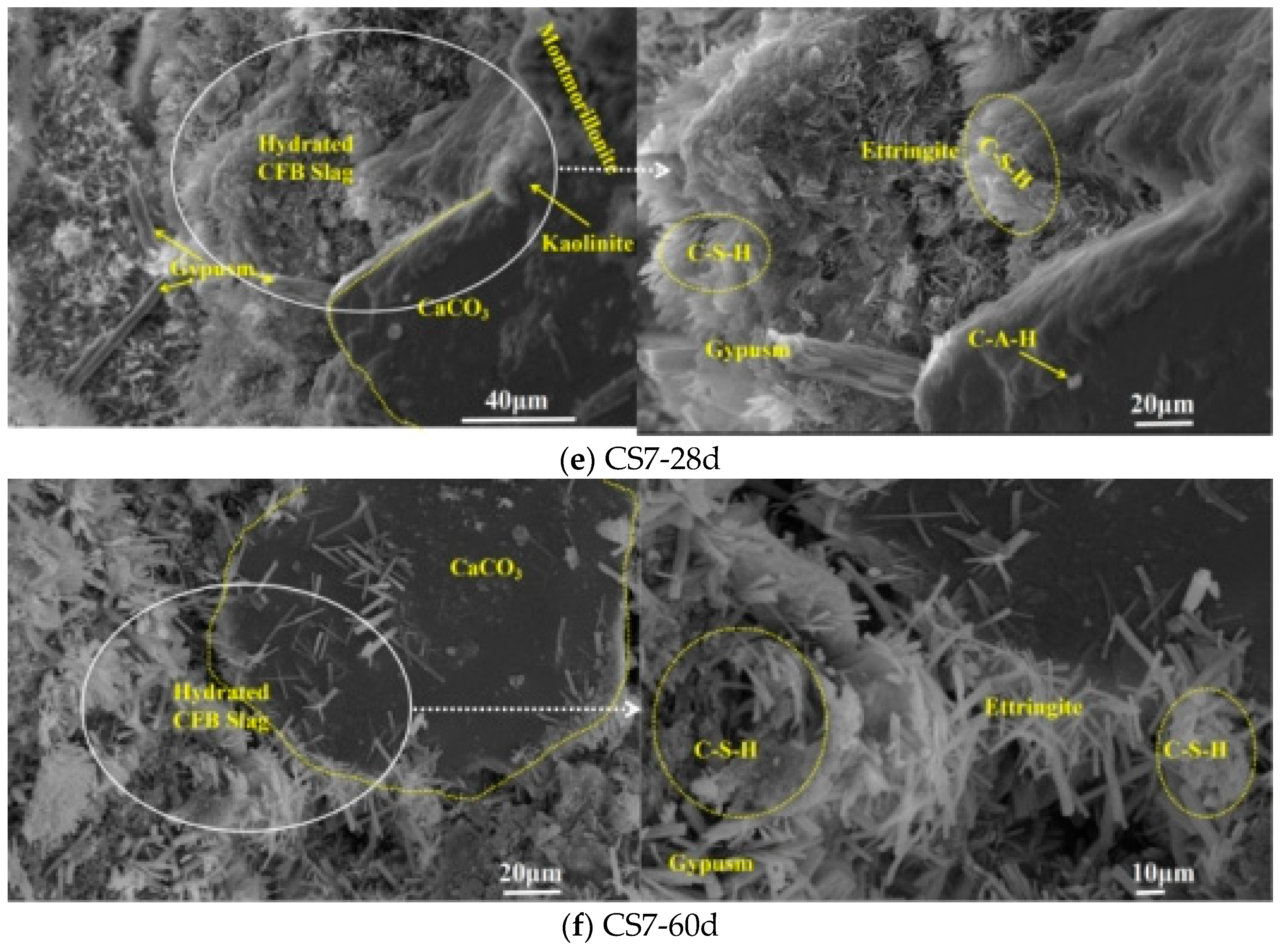
3.4. Microstructure
4. Conclusions
- (1)
- The strength (UCS, SS) of cement-CFBS-stabilized clay increases first and then decreases with the increase of CFBS content. When CFBS content is 80% (CS8), it reaches the peak. The unconfined compressive strength monotonically increases with age. UCS reached 10.7 MPa at 180d;
- (2)
- CFBS as a cement-stabilized clay admixture can significantly improve water stability. The water immersion resistance of cement–CFBS-stabilized clay increases first and then decreases with an increase in CFBS content. When the CFBS content is 70–80%, water immersion resistance was best. For shrinkage performance, the volume stability of cement–CFBS-stabilized clay was the best when CFB slag content was 70%;
- (3)
- The reaction mechanism of CFBS in cement-stabilized clay has two aspects: (a) The active silicon and aluminum substances in CFBS are easily dissolved, which accelerates the formation of CSH and AFt, and makes the structure dense and causes the strength increase. (b) The volumes of AFt and gypsum increase in the generation process, causing the mixture to expand, making up for the volume shrinkage and improving the strength and stability of cement-stabilized clay;
- (4)
- At present, current research focuses on cement-stabilized clay prone to water loss and shrinkage cracking, and CFBS has expansibility, it cannot be widely used. However, we studied the inhibition mechanism of CFBS on the shrinkage of cement-stabilized clay and the improvement mechanism of mechanical properties, providing theoretical and reference for the use of CFBS. However, the cement and CFBS systems are complex and the base materials include gravel, etc. Future research needs to study the inhibitory effect of CFBS on the shrinkage of cement-stabilized base materials. In addition, the test standard of cement-CFBS stabilized clay should be established to make CFBS resource utilization.
Author Contributions
Funding
Institutional Review Board Statement
Informed Consent Statement
Data Availability Statement
Conflicts of Interest
References
- Mola-Abasi, H.; Shooshpasha, I. Influence of zeolite and cement additions on mechanical behavior of sandy soil. J. Rock Mech. Geotech. Eng. 2016, 8, 746–752. [Google Scholar] [CrossRef] [Green Version]
- Paula, F.A.; Andry, R.; Harifidy, R.; Ouali, A.; Daniel, L.; Dimitri, D. Effect of fly ash on microstructural and resistance characteristics of dredged sediment stabilized with lime and cement. Constr. Build. Mater. 2020, 272, 121637. [Google Scholar]
- Liu, H.; Zhao, J.; Wang, Y.; Yi, N.; Cui, C. Strength Performance and Microstructure of Calcium Sulfoaluminate Cement-Stabilized Soft Soil. Sustainability 2021, 13, 2295. [Google Scholar] [CrossRef]
- Wang, J.; Li, X.; Wen, H.; Muhunthan, B. Shrinkage cracking model for cementitiously stabilized layers for use in the mechanistic-empirical pavement design guide. Transp. Geotech. 2020, 24, 100386. [Google Scholar] [CrossRef]
- Kangni-Foli, E.; Poyet, S.; Le Bescop, P.; Charpentier, T.; Bernachy-Barbé, F.; Dauzères, A.; L’Hôpital, E.; d’Espinose de Lacaillerie, J.-B. Carbonation of model cement pastes: The mineralogical origin of microstructural changes and shrinkage. Cem. Concr. Res. 2021, 144, 106446. [Google Scholar] [CrossRef]
- Wang, J.; Wen, H.; Muhunthan, B. Development of test methods to characterize the shrinkage properties of cementitiously stabilized materials. Transp. Geotech. 2020, 25, 100405. [Google Scholar] [CrossRef]
- Xue, Y.; Hou, H.; Zhu, S.; Zha, J. Utilization of municipal solid waste incineration ash in stone mastic asphalt mixture: Pavement performance and environmental impact. Constr. Build. Mater. 2008, 23, 989–996. [Google Scholar] [CrossRef]
- Zhang, S.; Yang, X.; Xie, S.; Yin, P. Experimental study on improving the engineering properties of coarse grain sulphate saline soils with inorganic materials. Cold Reg. Sci. Technol. 2020, 170, 102909. [Google Scholar] [CrossRef]
- Subramanian, S.; Khan, Q.; Ku, T. Effect of sand on the stiffness characteristics of cement-stabilized clay. Constr. Build. Mater. 2020, 264, 120192. [Google Scholar] [CrossRef]
- Xu, F.; Wei, H.; Qian, W.; Chen, X.; Xu, T.; He, Y.; Wen, G. Experimental investigation on replacing cement by sintered limestone ash from the steelmaking industry for cement-stabilized soil: Engineering performances and micro-scale analysis. Constr. Build. Mater. 2020, 235. [Google Scholar] [CrossRef]
- Amini, O.; Ghasemi, M. Laboratory study of the effects of using magnesium slag on the geotechnical properties of cement stabilized soil. Constr. Build. Mater. 2019, 223, 409–420. [Google Scholar] [CrossRef]
- Goodarzi, A.R.; Salimi, M. Stabilization treatment of a dispersive clayey soil using granulated blast furnace slag and basic oxygen furnace slag. Appl. Clay Sci. 2015, 108, 61–69. [Google Scholar] [CrossRef]
- Xiaoyuan, W.; Pengju, H.; Xiaohong, B.; Xiangyu, L. Influences of slag on properties of lightweight cement-treated soils subjected to sulfate corrosion. Constr. Build. Mater. 2019, 205, 511–518. [Google Scholar] [CrossRef]
- Lin, M.; Lu, X.; Wang, Q.; Pan, Z.; Hong, Y.; Ji, X. The experimental study of fly ash recirculation combustion characteristics on a circulating fluidized bed combustor. Fuel Process. Technol. 2014, 118, 192–199. [Google Scholar]
- Anthony, E.J.; Berry, E.E.; Blondin, J.; Bulewicz, E.M.; Burwell, S. Advanced ash management technologies for CFBC ash. Waste Manag. 2003, 23, 503–516. [Google Scholar] [CrossRef]
- Zhou, M.; Chen, P.; Chen, X.; Ge, X.; Wang, Y. Study on hydration characteristics of circulating fluidized bed combustion fly ash (CFBCA). Constr. Build. Mater. 2020, 251, 118993. [Google Scholar] [CrossRef]
- Lee, H.K.; Jeon, S.-M.; Lee, B.Y.; Kim, H.-K. Use of circulating fluidized bed combustion bottom ash as a secondary activator in high-volume slag cement. Constr. Build. Mater. 2020, 234, 117240. [Google Scholar] [CrossRef]
- Jun, W.; Li, L.; Yongfeng, D.; Guoping, Z.; Annan, Z.; Qiong, W. Distinguishing the effects of cementation versus density on the mechanical behavior of cement-based stabilized clays. Constr. Build. Mater. 2020, 271, 121571. [Google Scholar]
- Zhang, J.; Weng, X.; Liu, J.; Liu, W.; Gao, R.; Lin, K. Experimental research on mechanical property and water stability of complex stabilized sandy soil. Mater. Rep. 2014, 28, 115–119. [Google Scholar]
- Wei, Y.; Faqin, D.; Yuequan, D.; Ping, H. Influence of different pretreatment methods on hydrothermal synthesis of calcium sulfate whisker from CFBC ash and slag. Mater. Rep. 2013, 27, 73–75. [Google Scholar]
- Wang, D.; Gao, X.; Liu, X.; Zeng, G. Strength, durability and microstructure of granulated blast furnace slag-modified magnesium oxychloride cement solidified waste sludge. J. Clean. Prod. 2021, 292, 126072. [Google Scholar] [CrossRef]
- Zhou, M.; Cheng, X.; Chen, X. Studies on the Volumetric Stability and Mechanical Properties of Cement-Fly-Ash-Stabilized Steel Slag. Materials 2021, 14, 495. [Google Scholar] [CrossRef] [PubMed]
- Barišić, I.; Dimter, S.; Rukavina, T. Strength properties of steel slag stabilized mixes. Compos. Part B 2014, 58, 386–391. [Google Scholar] [CrossRef]
- Buritatum, A.; Horpibulsuk, S.; Udomchai, A.; Suddeepong, A.; Takaikaew, T.; Vichitcholchai, N.; Horpibulsuk, J.; Arulrajah, A. Durability improvement of cement stabilized pavement base using natural rubber latex. Transp. Geotech. 2021, 28, 100518. [Google Scholar] [CrossRef]
- Li, X.; Chen, Q.; Huang, K.; Ma, B.; Wu, B. Cementitious properties and hydration mechanism of circulating fluidized bed combustion (CFBC) desulfurization ashes. Constr. Build. Mater. 2012, 36, 182–187. [Google Scholar] [CrossRef]
- Lin, M.; Wang, W.; Li, Y. Preparation of inorganic compound early strength agent and its effect on properties of cement stabilized macadm material. Mater. Rep. 2018, 32, 511–516. [Google Scholar]


| Sample | SiO2 | Fe2O3 | CaO | MgO | SO3 | Loss | f-CaO |
|---|---|---|---|---|---|---|---|
| CFBS (%) | 46.6 | 3.6 | 7.1 | 0.6 | 6.4 | 3.7 | 3.63 |
| Cement Type | Specific Surface Area/m2·kg−1 | Standard Consistency/% | Setting Time/Min | Flexural Strength/MPa | Compressive Strength/MPa | |||
|---|---|---|---|---|---|---|---|---|
| Initial Setting | Final Coagulation | 7d | 28d | 7d | 28d | |||
| Zhuoyue PSA32.5 | 223 | 30.6 | 201 | 266 | 5.5 | 8.0 | 25.5 | 43.3 |
| Sample | Mass Fraction of Different Materials/% | Compaction Test Results | |||
|---|---|---|---|---|---|
| Cement | Clay | CFBS | Maximum Dry Density/g·cm−3 | Optimum Moisture Content/% | |
| CS0 | 6 | 100 | 0 | 1.895 | 12.7 |
| CS6 | 6 | 40 | 60 | 1.760 | 13.2 |
| CS7 | 6 | 30 | 70 | 1.754 | 14.5 |
| CS8 | 6 | 20 | 80 | 1.740 | 15.9 |
| CS10 | 6 | 0 | 100 | 1.600 | 18.6 |
| Addition of CFBS (%) | Sample No. | Shrinkage Strain (10−6) | Average (10−6) | Dispersion Coefficient (CV) |
|---|---|---|---|---|
| 0% | 1 | 2470 | 2490 | 0.7 |
| 2 | 2509 | |||
| 3 | 2491 | |||
| 60% | 1 | 419 | 420 | 1.1 |
| 2 | 416 | |||
| 70% | 3 | 425 | ||
| 1 | 213 | 221 | 4.5 | |
| 2 | 218 | |||
| 3 | 232 | |||
| 80% | 1 | −307 | −298 | 3.9 |
| 2 | −285 | |||
| 3 | −302 | |||
| 100% | 1 | −917 | −903 | 1.6 |
| 2 | −887 | |||
| 3 | −905 |
Publisher’s Note: MDPI stays neutral with regard to jurisdictional claims in published maps and institutional affiliations. |
© 2021 by the authors. Licensee MDPI, Basel, Switzerland. This article is an open access article distributed under the terms and conditions of the Creative Commons Attribution (CC BY) license (https://creativecommons.org/licenses/by/4.0/).
Share and Cite
Zhou, M.; Liu, X.; Chen, X.; Gao, P. Study on Strength, Water Stability, Shrinkage, and Microstructure of CFB Slag Modified Cement Stabilized Clay. Materials 2021, 14, 7460. https://doi.org/10.3390/ma14237460
Zhou M, Liu X, Chen X, Gao P. Study on Strength, Water Stability, Shrinkage, and Microstructure of CFB Slag Modified Cement Stabilized Clay. Materials. 2021; 14(23):7460. https://doi.org/10.3390/ma14237460
Chicago/Turabian StyleZhou, Mingkai, Xinyue Liu, Xiao Chen, and Peng Gao. 2021. "Study on Strength, Water Stability, Shrinkage, and Microstructure of CFB Slag Modified Cement Stabilized Clay" Materials 14, no. 23: 7460. https://doi.org/10.3390/ma14237460