
Revealing the Dynamic Characteristics of Composite Material-Based Miura-Origami Tube

Abstract
:1. Introduction
2. Materials and Methods
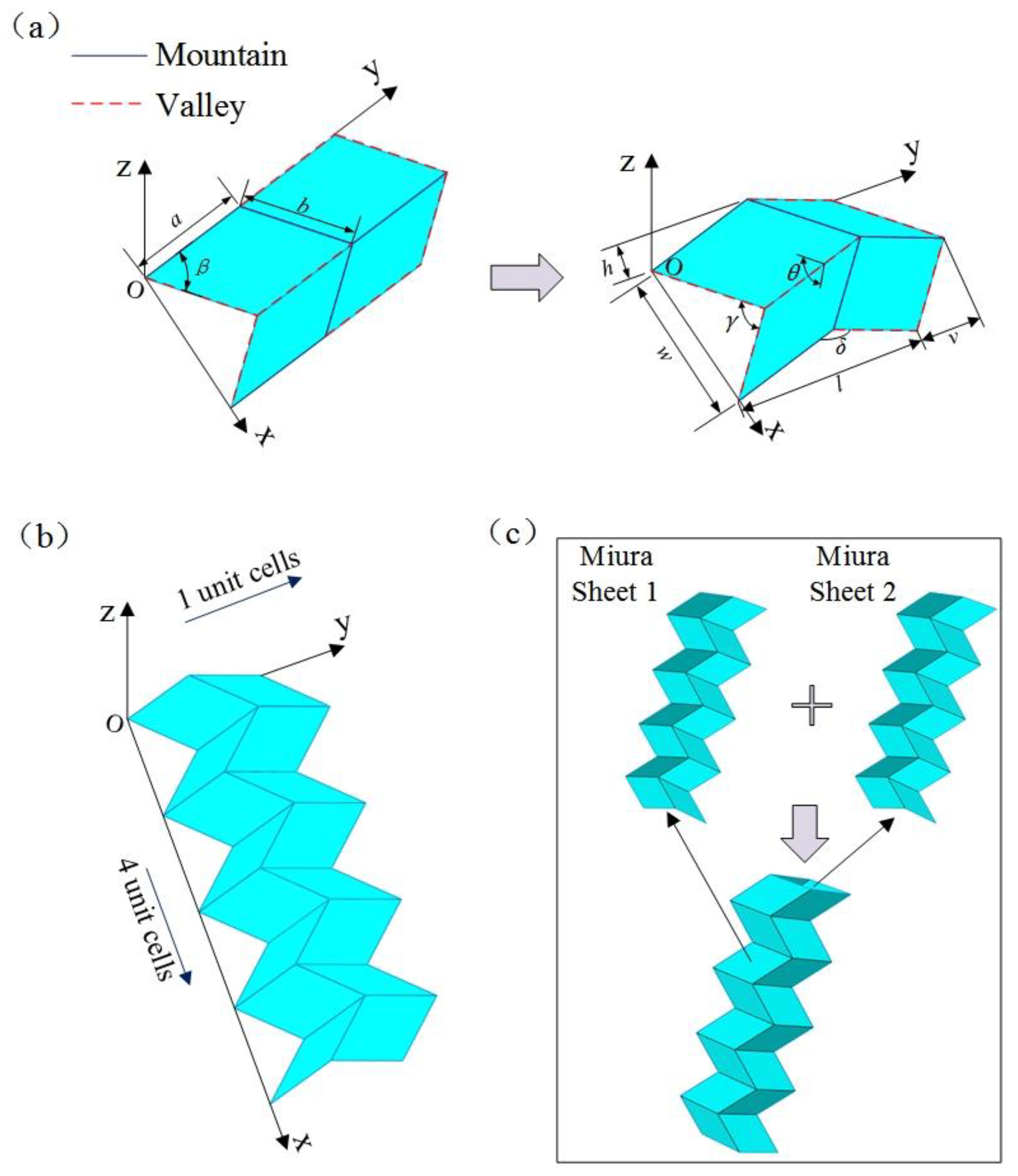
2.1. Geometric Design of the Miura Tube
2.1.1. Miura Sheet
2.1.2. Miura Tube
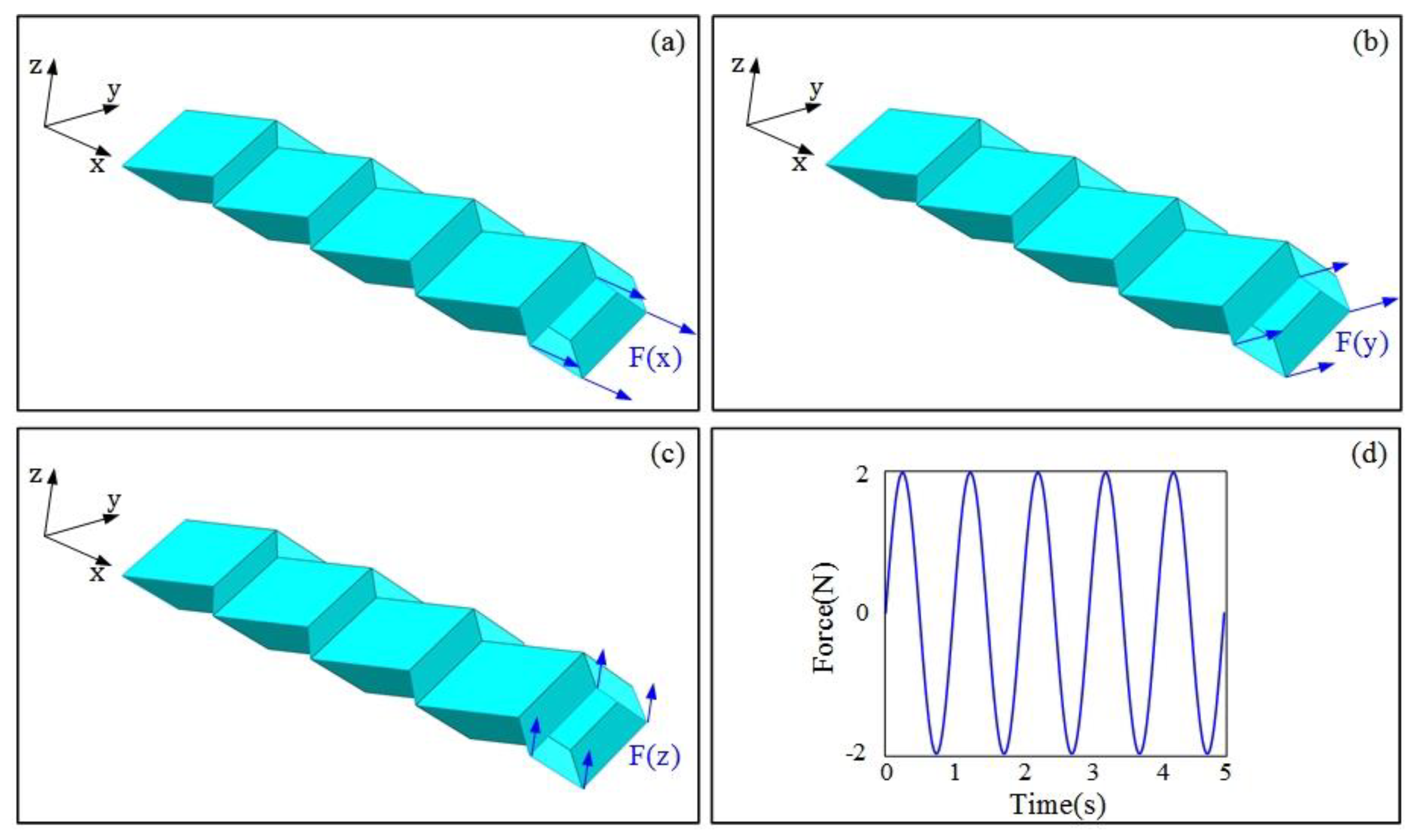
2.2. Finite Element Modelling
3. Results and Discussion
3.1. The Natural Frequency
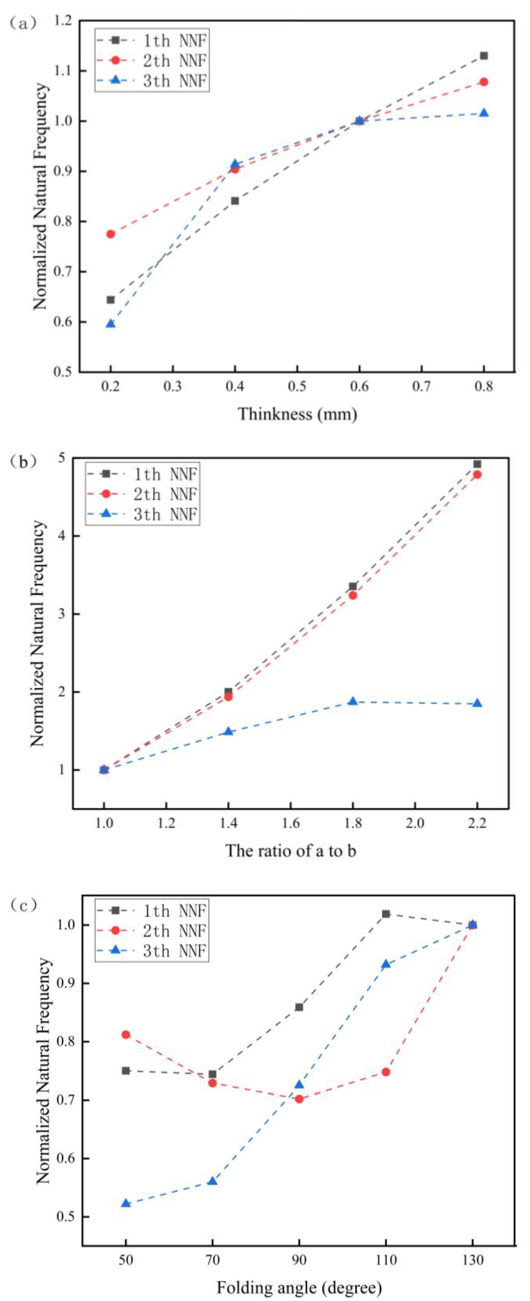
3.1.1. Effects of Structural Parameters on the Natural Frequency (NF)
3.1.2. Effects of Material Parameters on the Natural Frequency
3.2. Study on Dynamic Displacement Response
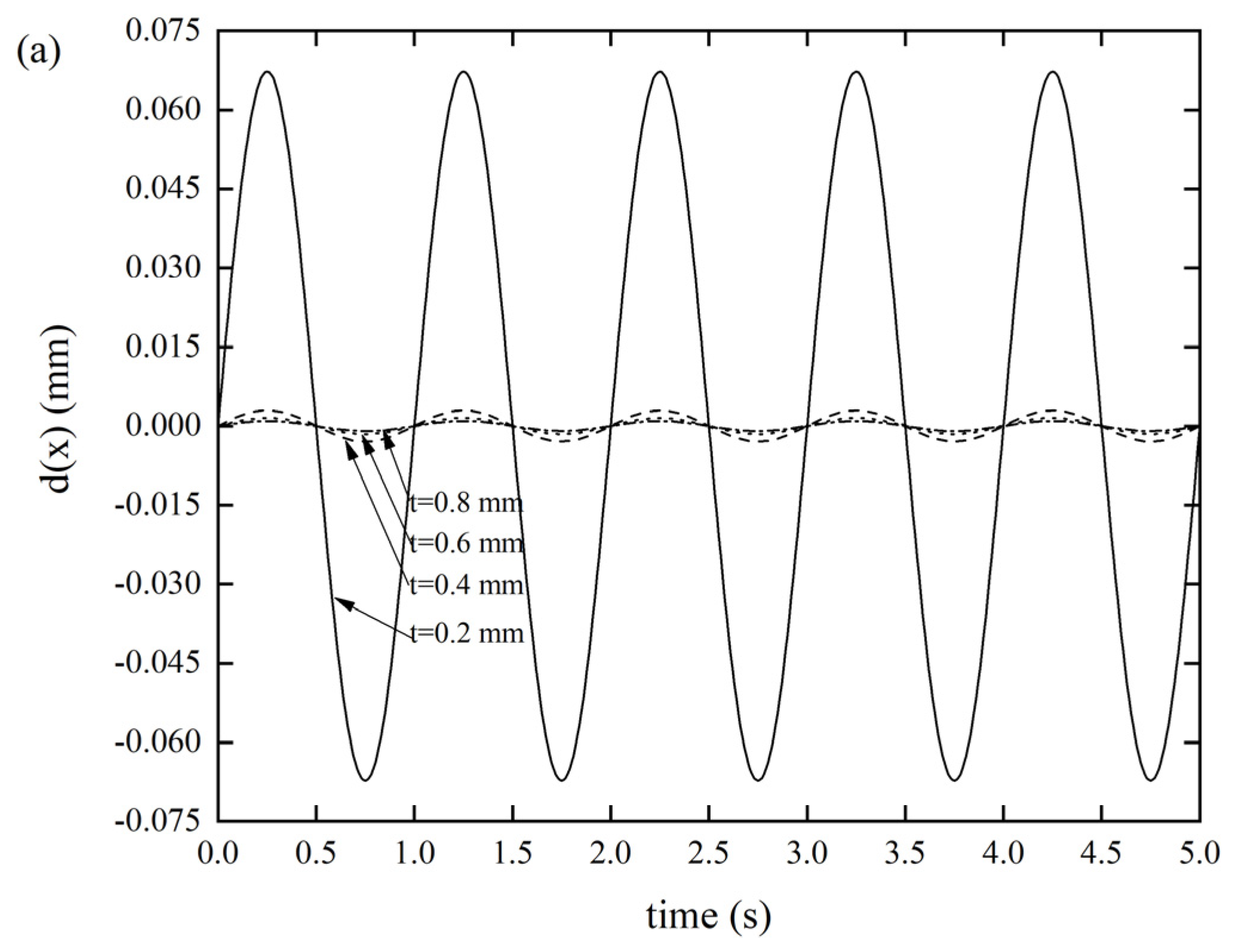
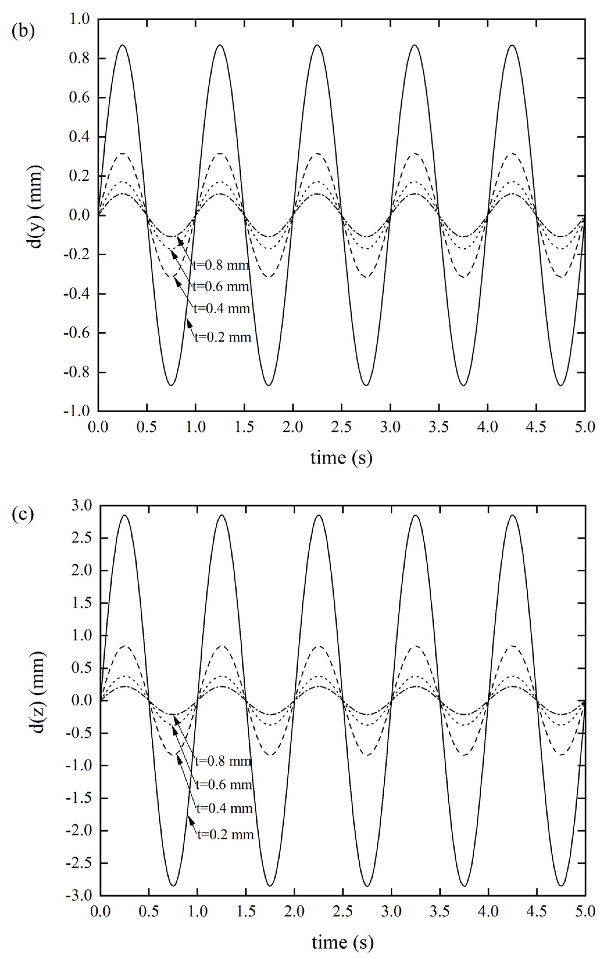
3.2.1. Effects of the Wall Thickness on the DDR
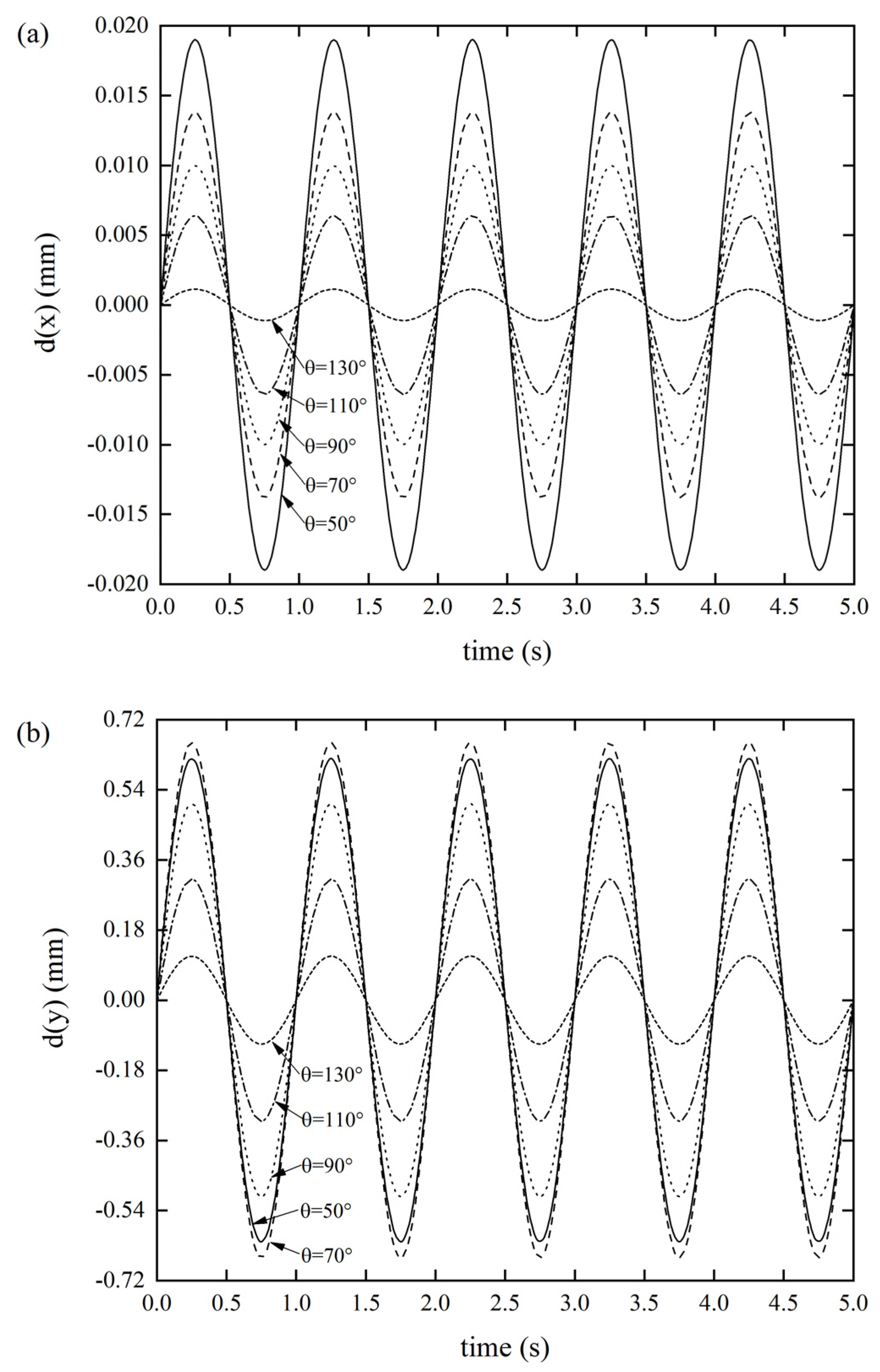
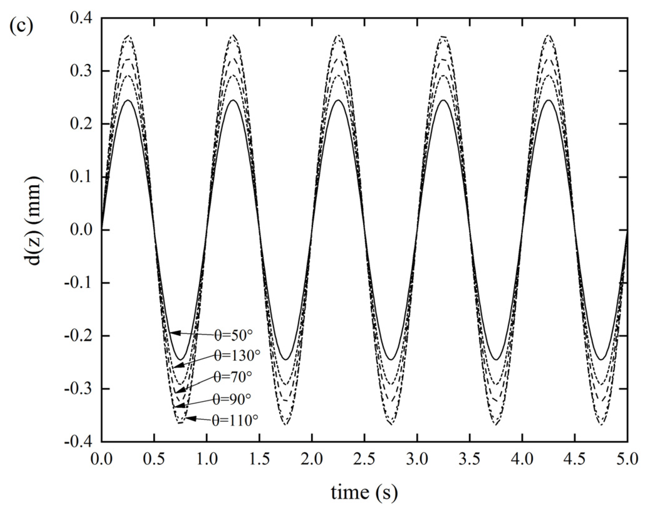
3.2.2. Effects of the folding angle θ on the DDR
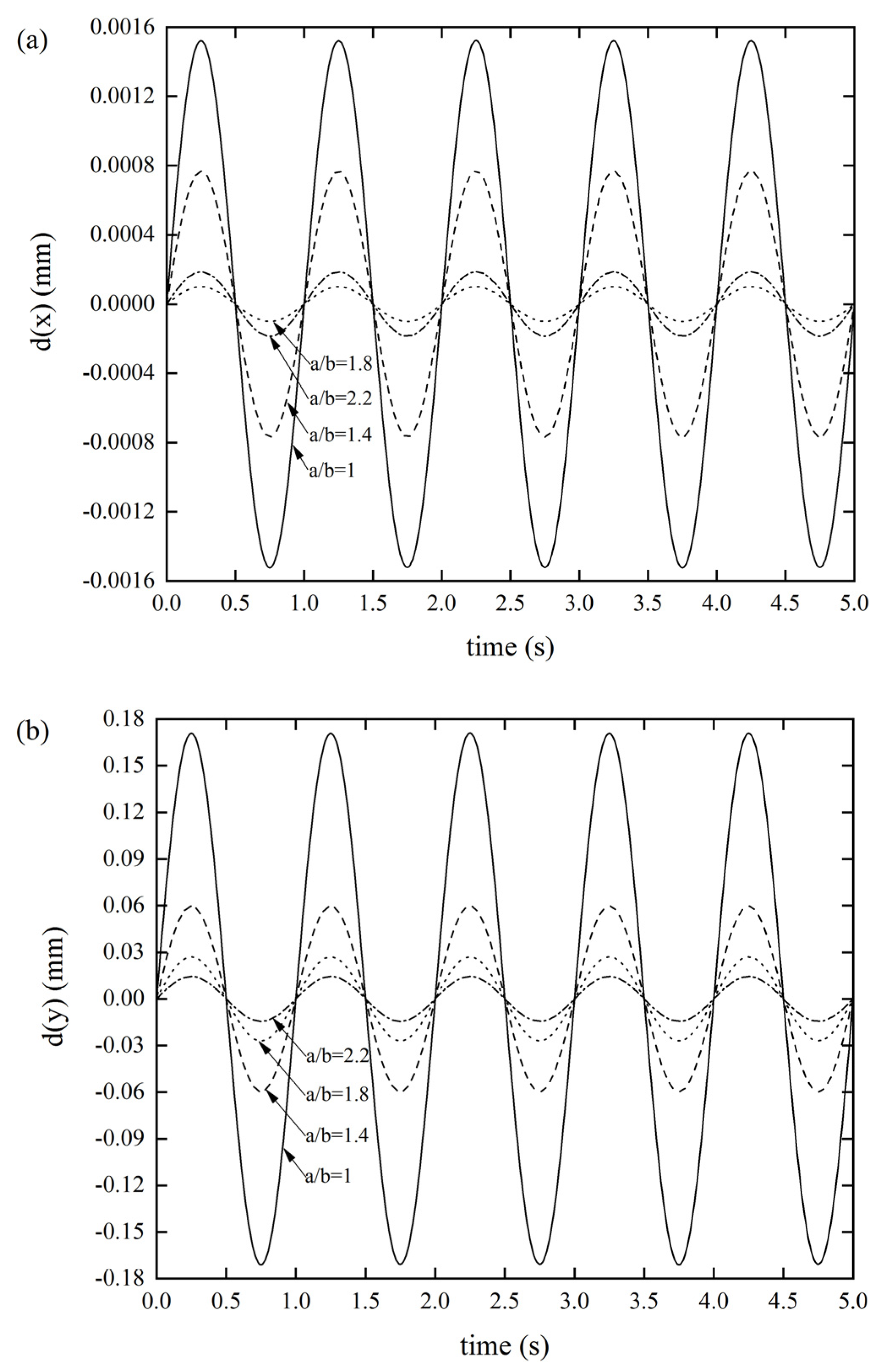
3.2.3. Effects of the Parallelogram Side Length Ratio a/b on the DDR
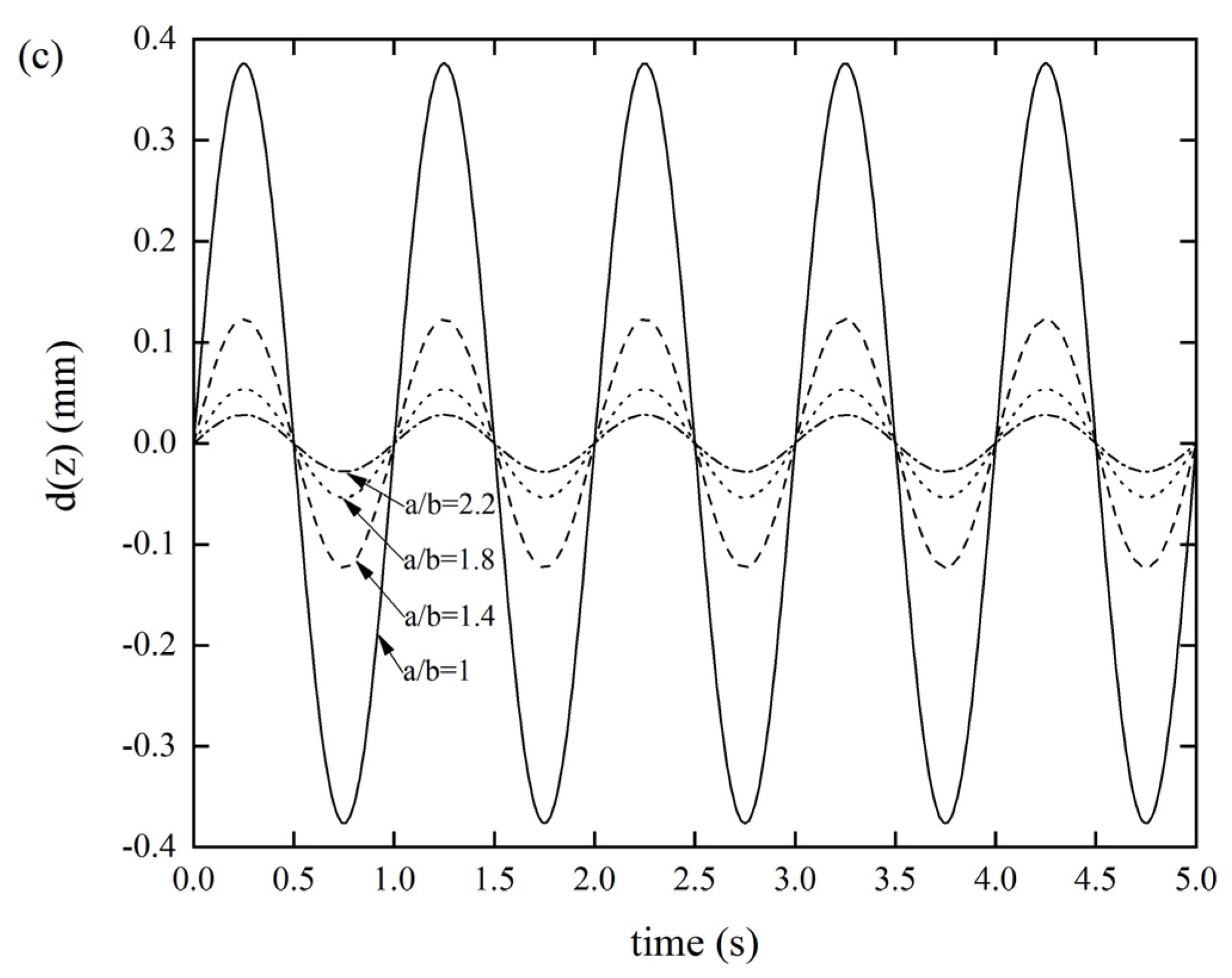
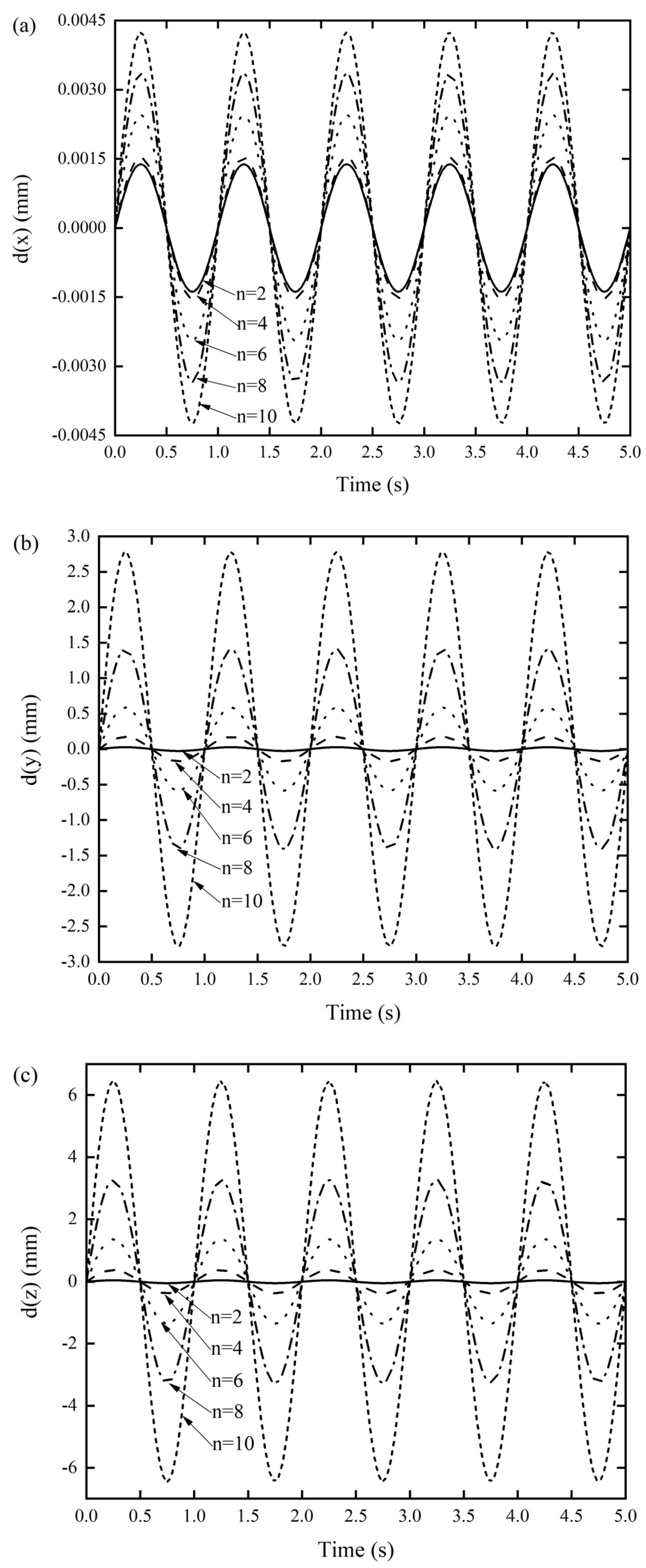
3.3. Effects of the Number of Arrangements of Miura Sheet Units
4. Conclusions
Author Contributions
Funding
Institutional Review Board Statement
Informed Consent Statement
Data Availability Statement
Acknowledgments
Conflicts of Interest
References
- Yasuda, H.; Yang, J. Reentrant origami-based metamaterials with negative Poisson’s ratio and bistability. Phys. Rev. Lett. 2015, 114, 185502. [Google Scholar] [CrossRef] [PubMed] [Green Version]
- Liu, K.; Tachi, T.; Paulino, G.H. Invariant and smooth limit of discrete geometry folded from bistable origami leading to multistable metasurfaces. Nat. Commun. 2019, 10, 1–10. [Google Scholar] [CrossRef] [PubMed] [Green Version]
- Townsend, S.; Adams, R.; Robinson, M.; Hanna, B.; Theobald, P. 3D printed origami honeycombs with tailored out-of-plane energy absorption behavior. Mater. Des. 2020, 195, 108930. [Google Scholar] [CrossRef]
- Liu, J.; Fan, X.; Wen, G.; Qing, Q.; Wang, H.; Zhao, G. A novel design framework for structures/materials with enhanced mechanical performance. Materials 2018, 11, 576. [Google Scholar] [CrossRef] [PubMed] [Green Version]
- Miura, K. Method of Packaging and Deployment of Large Membranes in Space; The Institute of Space and Astronautical Science Report; The Institute of Space and Astronautical Science: Sagamihara, Japan, 1985; Volume 618. [Google Scholar]
- Chen, T.; Bilal, O.R.; Lang, R.; Daraio, C.; Shea, K. Autonomous deployment of a solar panel using elastic origami and distributed shape-memory-polymer actuators. Phys. Rev. Appl. 2019, 11, 064069. [Google Scholar] [CrossRef] [Green Version]
- Pillai, S.S.; Sreedharan, P. Design, manufacturing and testing of re-configurable crawling modular robot inspired from origami. IOP Conf. Ser. Mater. Sci. Eng. 2019, 577, 012142. [Google Scholar] [CrossRef]
- Overvelde, J.T.; de Jong, T.A.; Shevchenko, Y.; Becerra, S.A.; Whitesides, G.M.; Weaver, J.C.; Hoberman, C.; Bertoldi, K. A three-dimensional actuated origami-inspired transformable metamaterial with multiple degrees of freedom. Nat. Commun. 2016, 7, 1–8. [Google Scholar] [CrossRef]
- Yang, K.; Xu, S.; Zhou, S.; Xie, Y.M. Multi-objective optimization of multi-cell tubes with origami patterns for energy absorption. Thin Walled Struct. 2018, 123, 100–113. [Google Scholar] [CrossRef]
- Zhou, Y.; Zhang, Q.; Cai, J.; Zhang, Y.; Yang, R.; Feng, J. Experimental study of the hysteretic behavior of energy dissipation braces based on Miura origami. Thin Walled Struct. 2021, 167, 108196. [Google Scholar] [CrossRef]
- Yin, H.; Zheng, X.; Wen, G.; Zhang, C.; Wu, Z. Design optimization of a novel bio-inspired 3D porous structure for crashworthiness. Compos. Struct. 2021, 255, 112897. [Google Scholar] [CrossRef]
- Kuribayashi, K.; Tsuchiya, K.; You, Z.; Tomus, D.; Umemoto, M.; Ito, T.; Sasaki, M. Self-deployable origami stent grafts as a biomedical application of Ni-rich TiNi shape memory alloy foil. Mater. Sci. Eng. A 2006, 419, 131–137. [Google Scholar] [CrossRef]
- Taylor, A.J.; Slutzky, T.; Feuerman, L.; Ren, H.; Tokuda, J.; Nilsson, K.; Tse, Z.T.H. MR-Conditional SMA-Based Origami Joint. IEEE/ASME Trans. Mechatron. 2019, 24, 883–888. [Google Scholar] [CrossRef]
- Cheng, Q.; Song, Z.; Ma, T.; Smith, B.B.; Tang, R.; Yu, H.; Jiang, H.; Chan, C.K. Folding Paper-Based Lithium-Ion Batteries for Higher Areal Energy Densities. Nano Lett. 2013, 13, 4969–4974. [Google Scholar] [CrossRef]
- Song, Z.; Ma, T.; Tang, R.; Cheng, Q.; Wang, X.; Krishnaraju, D.; Panat, R.; Chan, C.K.; Yu, H.; Jiang, H. Origami lithium-ion batteries. Nat. Commun. 2014, 5, 3140. [Google Scholar] [CrossRef]
- Hu, F.; Wang, W.; Cheng, J.; Bao, Y. Origami spring–inspired metamaterials and robots: An attempt at fully programmable robotics. Sci. Prog. 2020, 103, 0036850420946162. [Google Scholar] [CrossRef]
- Faber, J.A.; Arrieta, A.F.; Studart, A.R. Bioinspired spring origami. Science 2018, 359, 1386–1391. [Google Scholar] [CrossRef] [PubMed] [Green Version]
- Rus, D.; Tolley, M.T. Design, fabrication and control of origami robots. Nat. Rev. Mater. 2018, 3, 101–112. [Google Scholar] [CrossRef]
- Santoso, J.; Onal, C.D. An Origami Continuum Robot Capable of Precise Motion Through Torsionally Stiff Body and Smooth Inverse Kinematics. Soft Robot. 2021, 8, 371–386. [Google Scholar] [CrossRef]
- Zhang, S.; Ke, X.; Jiang, Q.; Ding, H.; Wu, Z. Programmable and reprocessable multifunctional elastomeric sheets for soft origami robots. Sci. Robot. 2021, 6, eabd6107. [Google Scholar] [CrossRef] [PubMed]
- Liu, J.; Chen, T.; Zhang, Y.; Wen, G.; Qing, Q.; Wang, H.; Sedaghati, R.; Xie, Y.M. On sound insulation of pyramidal lattice sandwich structure. Compos. Struct. 2018, 208, 385–394. [Google Scholar] [CrossRef] [Green Version]
- Fang, H.; Yu, X.; Cheng, L. Reconfigurable origami silencers for tunable and programmable sound attenuation. Smart Mater. Struct. 2018, 27, 095007. [Google Scholar] [CrossRef] [Green Version]
- Wen, G.; Zhang, Y.; Liu, J. Sound insulation properties of sandwich structure with hemispheric shell cores: Numerical and experimental studies. Appl. Acoust. 2020, 162, 107209. [Google Scholar] [CrossRef]
- Lv, C.; Krishnaraju, D.; Konjevod, G.; Yu, H.; Jiang, H. Origami based Mechanical Metamaterials. Sci. Rep. 2014, 4, 5979. [Google Scholar] [CrossRef] [PubMed] [Green Version]
- Liu, S.; Lu, G.; Chen, Y.; Leong, W.Y. Deformation of the Miura-ori patterned sheet. Int. J. Mech. Sci. 2015, 99, 130–142. [Google Scholar] [CrossRef]
- Xiang, X.; Qiang, W.; Hou, B.; Tran, P.; Lu, G. Quasi-static and dynamic mechanical properties of Miura-ori metamaterials. Thin Walled Struct. 2020, 157, 106993. [Google Scholar] [CrossRef]
- Fischer, S.; Drechsler, K.; Kilchert, S.; Johnson, A. Mechanical tests for foldcore base material properties. Compos. Appl. Sci. Manuf. 2009, 40, 1941–1952. [Google Scholar] [CrossRef]
- Sareh, P.; Guest, S. Design of non-isomorphic symmetric descendants of the Miura-ori. Smart Mater. Struct. 2015, 24, 085002. [Google Scholar] [CrossRef]
- Zhang, J.; Karagiozova, D.; Lu, G.; Chen, P. Quasi-static in-plane compression of zig-zag folded metamaterials at large plastic strains. Thin Walled Struct. 2021, 159, 107285. [Google Scholar] [CrossRef]
- Wen, G.; Chen, G.; Long, K.; Wang, X.; Liu, J.; Xie, Y.M. Stacked-origami mechanical metamaterial with tailored multistage stiffness. Res. Sq. 2021. preprint. [Google Scholar] [CrossRef]
- Liu, J.; Xu, S.; Wen, G.; Xie, Y.M. Mechanical behaviour of a creased thin strip. Mech. Sci. 2018, 9, 91–102. [Google Scholar] [CrossRef] [Green Version]
- Cheung, K.C.; Tachi, T.; Calisch, S.; Miura, K. Origami interleaved tube cellular materials. Smart Mater. Struct. 2014, 23, 094012. [Google Scholar] [CrossRef] [Green Version]
- Liu, J.; Ou, H.; Zeng, R.; Zhou, J.; Long, K.; Wen, G.; Xie, Y.M. Fabrication, dynamic properties and multi-objective optimization of a metal origami tube with Miura sheets. Thin Walled Struct. 2019, 144, 106352. [Google Scholar] [CrossRef]
- Wu, H.; Fang, H.; Chen, L.; Xu, J. Transient Dynamics of a Miura-Origami Tube during Free Deployment. Phys. Rev. Appl. 2020, 14, 034068. [Google Scholar] [CrossRef]
- Han, H.; Sorokin, V.; Tang, L.; Cao, D. A nonlinear vibration isolator with quasi-zero-stiffness inspired by Miura-origami tube. Nonlinear Dyn. 2021, 105, 1313–1325. [Google Scholar] [CrossRef]
- Filipov, E.; Tachi, T.; Paulino, G.H. Origami tubes assembled into stiff, yet reconfigurable structures and metamaterials. Proc. Natl. Acad. Sci. USA 2015, 112, 12321–12326. [Google Scholar] [CrossRef] [Green Version]
- Chen, Y.; Lv, W.; Li, J.; You, Z. An Extended Family of Rigidly Foldable Origami Tubes. J. Mech. Robot. 2017, 9, 021002. [Google Scholar] [CrossRef]
- Filipov, E.; Paulino, G.H.; Tachi, T. Origami tubes with reconfigurable polygonal cross-sections. Proc. R. Soc. A Math. Phys. Eng. Sci. 2016, 472, 20150607. [Google Scholar] [CrossRef] [Green Version]
- Eidini, M.; Paulino, G.H. Unraveling metamaterial properties in zigzag-base folded sheets. Sci. Adv. 2015, 1, e1500224. [Google Scholar] [CrossRef] [Green Version]
- Eidini, M. Zigzag-base folded sheet cellular mechanical metamaterials. Extreme Mech. Lett. 2016, 6, 96–102. [Google Scholar] [CrossRef] [Green Version]
- Wang, F.; Gong, H.; Chen, X.; Chen, C.Q. Folding to Curved Surfaces: A Generalized Design Method and Mechanics of Origami-based Cylindrical Structures. Sci. Rep. 2016, 6, 33312. [Google Scholar] [CrossRef] [Green Version]
- Ma, J.; Song, J.; Chen, Y. An origami-inspired structure with graded stiffness. Int. J. Mech. Sci. 2018, 136, 134–142. [Google Scholar] [CrossRef]
- Zhu, H.; Chen, S.; Shen, T.; Wang, R.; Liu, J. CFRP Origami Metamaterial with Tunable Buckling Loads: A Numerical Study. Materials 2021, 14, 917. [Google Scholar] [CrossRef] [PubMed]
- Teoh, J.E.M.; An, J.; Feng, X.; Zhao, Y.; Chua, C.K.; Liu, Y. Design and 4D Printing of Cross-Folded Origami Structures: A Preliminary Investigation. Materials 2018, 11, 376. [Google Scholar] [CrossRef] [Green Version]
- Saito, K.; Pellegrino, S.; Nojima, T. Manufacture of Arbitrary Cross-Section Composite Honeycomb Cores Based on Origami Techniques. J. Mech. Des. 2014, 136, 051011. [Google Scholar] [CrossRef] [Green Version]
- Cui, J.; Poblete, F.R.; Zhu, Y. Origami/Kirigami-Guided Morphing of Composite Sheets. Adv. Funct. Mater. 2018, 28, 1802768. [Google Scholar] [CrossRef]
- Ye, H.; Ma, J.; Zhou, X.; Wang, H.; You, Z. Energy absorption behaviors of pre-folded composite tubes with the full-diamond origami patterns. Compos. Struct. 2019, 221, 110904. [Google Scholar] [CrossRef]
- Ciampaglia, A.; Fiumarella, D.; Niutta, C.B.; Ciardiello, R.; Belingardi, G. Impact response of an origami-shaped composite crash box: Experimental analysis and numerical optimization. Compos. Struct. 2020, 256, 113093. [Google Scholar] [CrossRef]
- Xu, Y.; Li, Y.; Zheng, N.; Zhao, Q.; Xie, T. Transparent origami glass. Nat. Commun. 2021, 12, 1–6. [Google Scholar] [CrossRef]
- Du, Y.; Keller, T.; Song, C.; Wu, L.; Xiong, J. Origami-inspired carbon fiber-reinforced composite sandwich materials—Fabrication and mechanical behavior. Compos. Sci. Technol. 2021, 205, 108667. [Google Scholar] [CrossRef]
- Wen, G.; He, J.; Liu, J.; Lin, Y. Design, analysis and semi-active control of a quasi-zero stiffness vibration isolation system with six oblique springs. Nonlinear Dyn. 2021, 106, 1–13. [Google Scholar] [CrossRef]
- Sinha, L.; Das, D.; Nayak, A.N.; Sahu, S.K. Experimental and numerical study on free vibration characteristics of laminated composite plate with/without cut-out. Compos. Struct. 2020, 256, 113051. [Google Scholar] [CrossRef]
- Gohari, S.; Sharifi, S.; Burvill, C.; Mouloodi, S.; Izadifar, M.; Thissen, P. Localized failure analysis of internally pressurized laminated ellipsoidal woven GFRP composite domes: Analytical, numerical, and experimental studies. Arch. Civ. Mech. Eng. 2019, 19, 1235–1250. [Google Scholar] [CrossRef]
- Wang, Y.; Wang, H.; Wei, J.; Lin, B.; Xu, J.; Fang, S. Finite element analysis of grinding process of long fiber reinforced ceramicmatrix woven composites: Modeling, experimental verification and material removal mechanism. Ceram. Int. 2019, 45, 15920–15927. [Google Scholar] [CrossRef]
- ABAQUS User’s Manual, Version 6.14; Dassault Systèmes Simulia Corp: Providence, RI, USA, 2014.
- Imran, M.; Shi, D.-Y.; Tong, L.-L.; Elahi, A.; Waqas, H.M.; Uddin, M. Multi-objective design optimization of composite submerged cylindrical pressure hull for minimum buoyancy factor and maximum buckling load capacity. Def. Technol. 2020, 17, 1190–1206. [Google Scholar] [CrossRef]
- Liu, J.; Wen, G.; Xie, Y.M. Layout optimization of continuum structures considering the probabilistic and fuzzy directional uncertainty of applied loads based on the cloud model. Struct. Multidiscip. Optim. 2015, 53, 81–100. [Google Scholar] [CrossRef]
- Sigmund, O.; Maute, K. Topology optimization approaches. Struct. Multidiscip. Optim. 2013, 48, 1031–1055. [Google Scholar] [CrossRef]
- Liu, J.; Ou, H.; He, J.; Wen, G.; Ou, L.; He, W. Topological Design of a Lightweight Sandwich Aircraft Spoiler. Materials 2019, 12, 3225. [Google Scholar] [CrossRef] [Green Version]
- Xie, Y.M.; Steven, G. A simple evolutionary procedure for structural optimization. Comput. Struct. 1993, 49, 885–896. [Google Scholar] [CrossRef]
- Liu, J.; Wen, G.; Huang, X. To avoid unpractical optimal design without support. Struct. Multidiscip. Optim. 2017, 56, 1589–1595. [Google Scholar] [CrossRef]
- Ma, Y.; Li, S.; Wang, J.; Ju, L.; Liu, X. Influence of defects on bending properties of 2D-T700/E44 composites prepared by improved compression molding process. Materials 2018, 11, 2132. [Google Scholar] [CrossRef] [Green Version]
- Khalid, M.Y.; Arif, Z.U.; Sheikh, M.F.; Nasir, M.A. Mechanical characterization of glass and jute fiber-based hybrid composites fabricated through compression molding technique. Int. J. Mater. Form. 2021, 14, 1–11. [Google Scholar] [CrossRef]
- Li, F.; Liu, J.; Yan, Y.; Rong, J.; Yi, J.; Wen, G. A time-variant reliability analysis method for non-linear limit-state functions with the mixture of random and interval variables. Eng. Struct. 2020, 213, 110588. [Google Scholar] [CrossRef]


| Material Properties | Values | |
|---|---|---|
| Young’s modulus/GPa | E1 | 121 |
| E2 | 8.6 | |
| E3 | 8.6 | |
| Shear modulus/GPa | G12 | 4.7 |
| G13 | 4.7 | |
| G23 | 3.1 | |
| Poisson’s ratio | v | 0.27 |
| density/(kg·m−3) | ρ | 1490 |
| Fixed Parameters | Changeable Parameters | NF | ||
|---|---|---|---|---|
| ω1/Hz | ω2/Hz | ω3/Hz | ||
| a = 10 mm, a/b = 1 θ = 130°, β = 55° ϕ = 0° | t = 0.2 mm | 616 | 1084 | 2785 |
| t = 0.4 mm | 804 | 1264 | 4277 | |
| t = 0.6 mm | 956 | 1398 | 4677 | |
| t = 0.8 mm | 1080 | 1507 | 4745 | |
| a = 10 mm, t = 0.6 mm θ = 130°, β = 55° ϕ = 0° | a/b = 1 | 956 | 1398 | 4677 |
| a/b = 1.4 | 1914 | 2709 | 6956 | |
| a/b = 1.8 | 3205 | 4528 | 8759 | |
| a/b = 2.2 | 4705 | 6695 | 8647 | |
| a = 10 mm, a/b = 1 t = 0.6 mm, β = 55° ϕ = 0° | θ = 50° | 717 | 1135 | 2443 |
| θ = 70° | 712 | 1019 | 2804 | |
| θ = 90° | 821 | 982 | 3390 | |
| θ = 110° | 974 | 1046 | 4359 | |
| θ = 130° | 956 | 1398 | 4677 | |
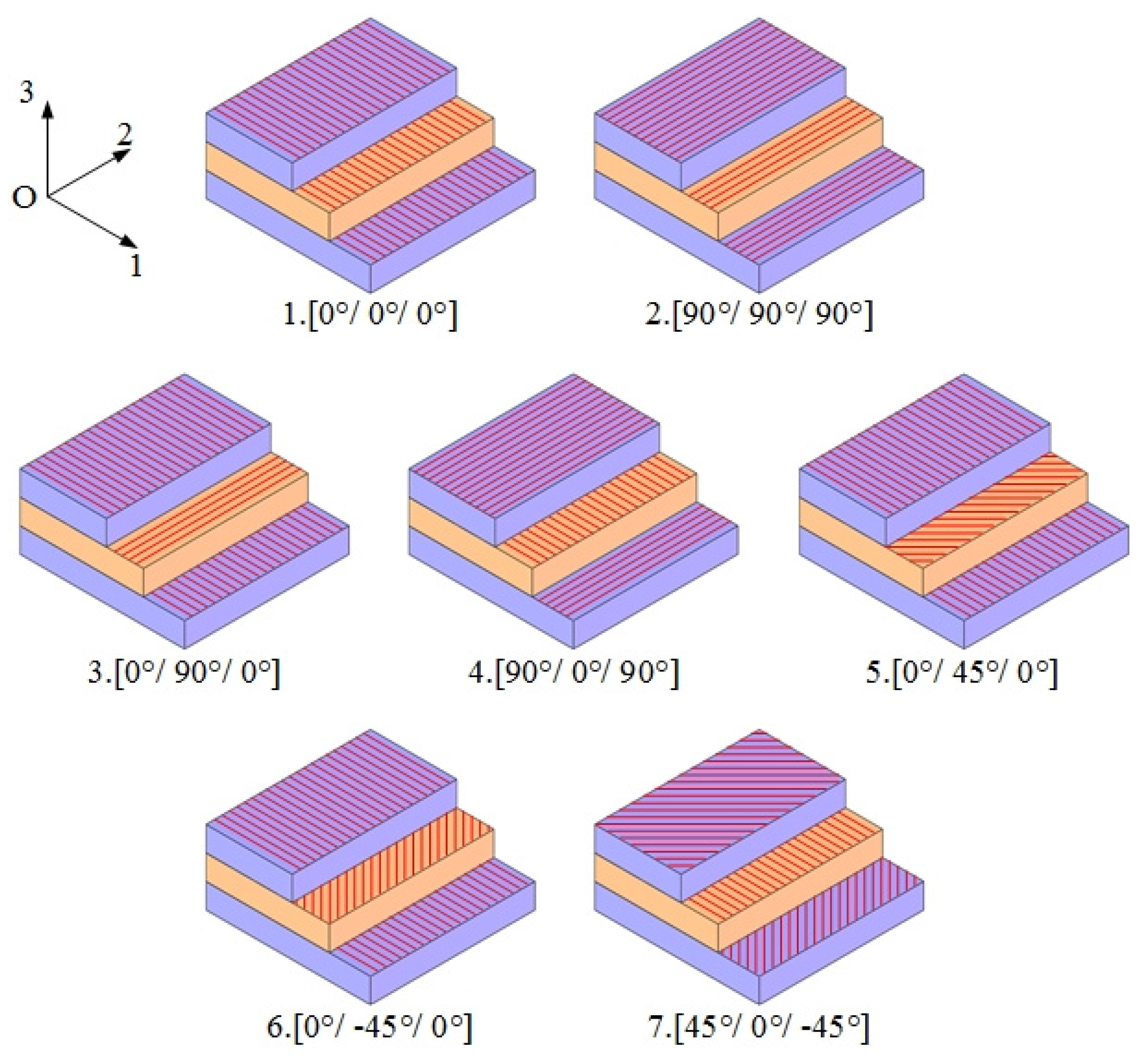
| Group | Layout Scheme | NNF | ||
|---|---|---|---|---|
| ω1/Hz | ω2/Hz | ω3/Hz | ||
| 1 | 0°/0°/0° | 956 | 1398 | 4677 |
| 2 | 90°/90°/90° | 647 | 1027 | 3608 |
| 3 | 0°/90°/0° | 1052 | 1572 | 5134 |
| 4 | 90°/0°/90° | 899 | 1473 | 4766 |
| 5 | 0°/45°/0° | 1006 | 1580 | 5489 |
| 6 | 0°/−45°/0° | 1002 | 1539 | 5315 |
| 7 | 45°/0°/−45° | 728 | 1322 | 4008 |
Publisher’s Note: MDPI stays neutral with regard to jurisdictional claims in published maps and institutional affiliations. |
© 2021 by the authors. Licensee MDPI, Basel, Switzerland. This article is an open access article distributed under the terms and conditions of the Creative Commons Attribution (CC BY) license (https://creativecommons.org/licenses/by/4.0/).
Share and Cite
Zhu, H.; Li, Z.; Wang, R.; Chen, S.; Zhang, C.; Li, F. Revealing the Dynamic Characteristics of Composite Material-Based Miura-Origami Tube. Materials 2021, 14, 6374. https://doi.org/10.3390/ma14216374
Zhu H, Li Z, Wang R, Chen S, Zhang C, Li F. Revealing the Dynamic Characteristics of Composite Material-Based Miura-Origami Tube. Materials. 2021; 14(21):6374. https://doi.org/10.3390/ma14216374
Chicago/Turabian StyleZhu, Houyao, Zhixin Li, Ruikun Wang, Shouyan Chen, Chunliang Zhang, and Fangyi Li. 2021. "Revealing the Dynamic Characteristics of Composite Material-Based Miura-Origami Tube" Materials 14, no. 21: 6374. https://doi.org/10.3390/ma14216374