
An Aggregation-Free Local Volume Fraction Formulation for Topological Design of Porous Structure


Abstract
:1. Introduction
2. Optimization Problem for Infill Structure
2.1. Formulation for Porous Structure Design
2.2. Augmented Lagrangian Method
2.3. Sensitivity Analysis
2.4. MMA Algorithm
3. Numerical Examples
3.1. Example 1
3.2. Example 2
3.3. Example 3
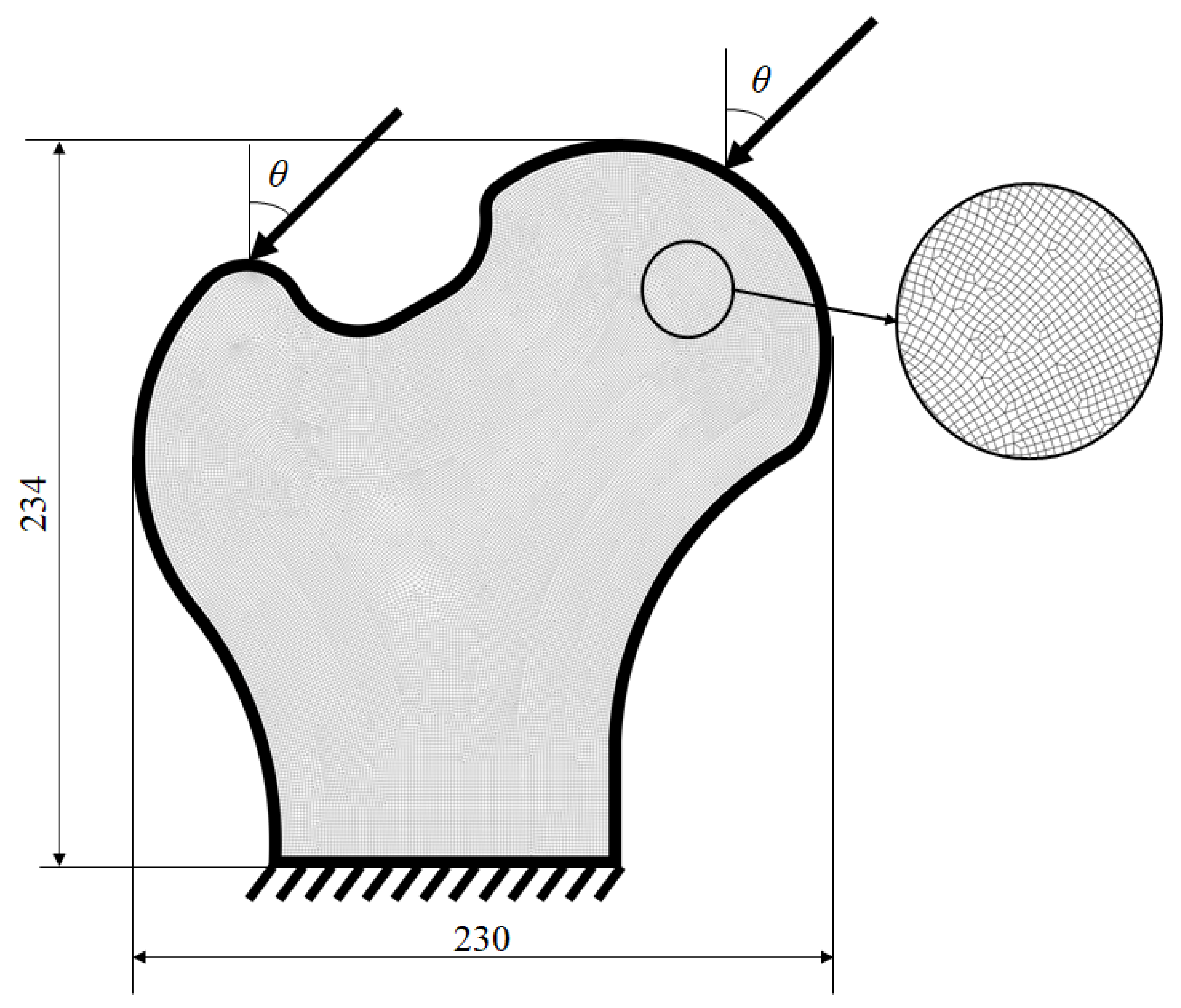
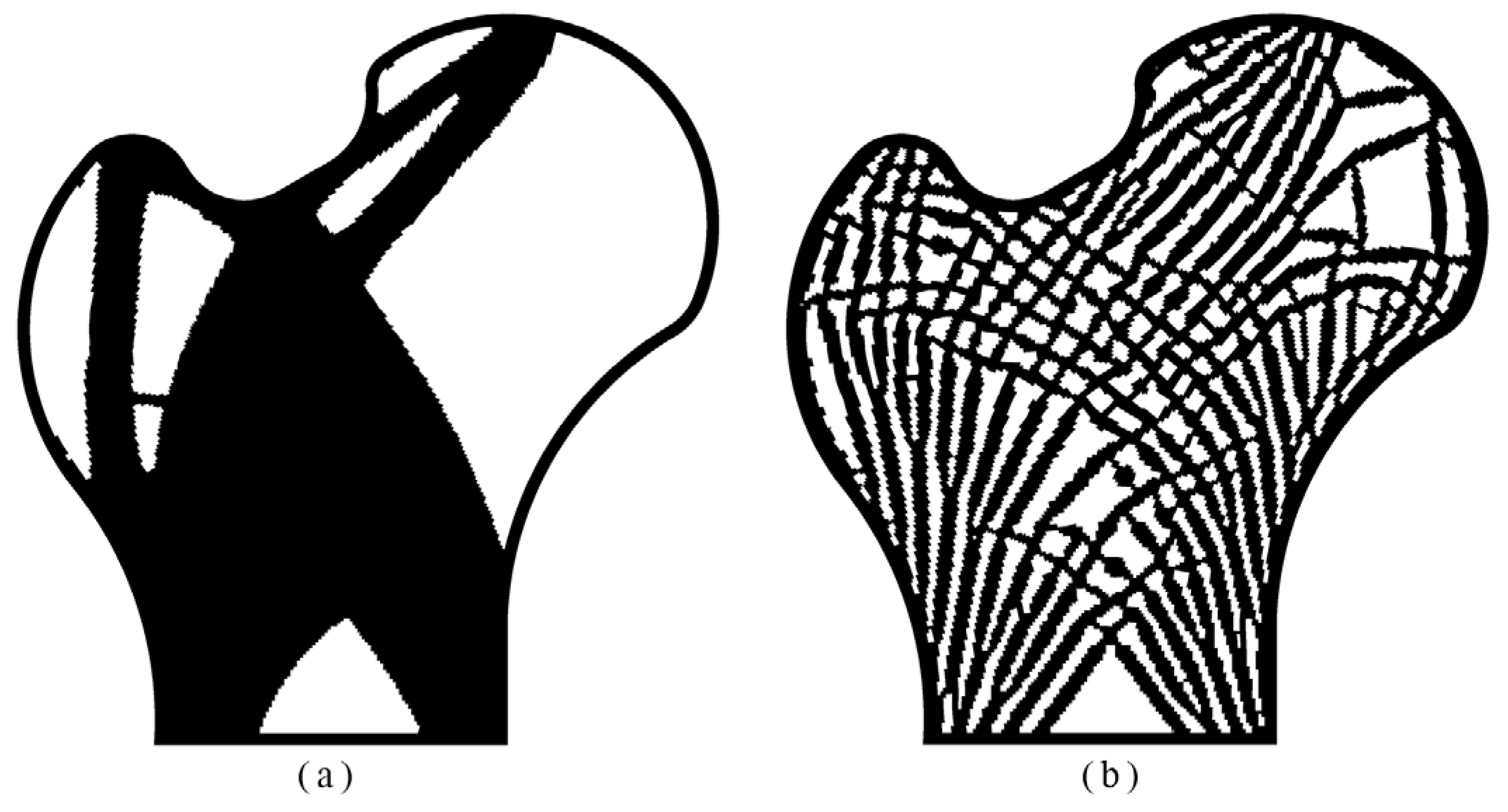
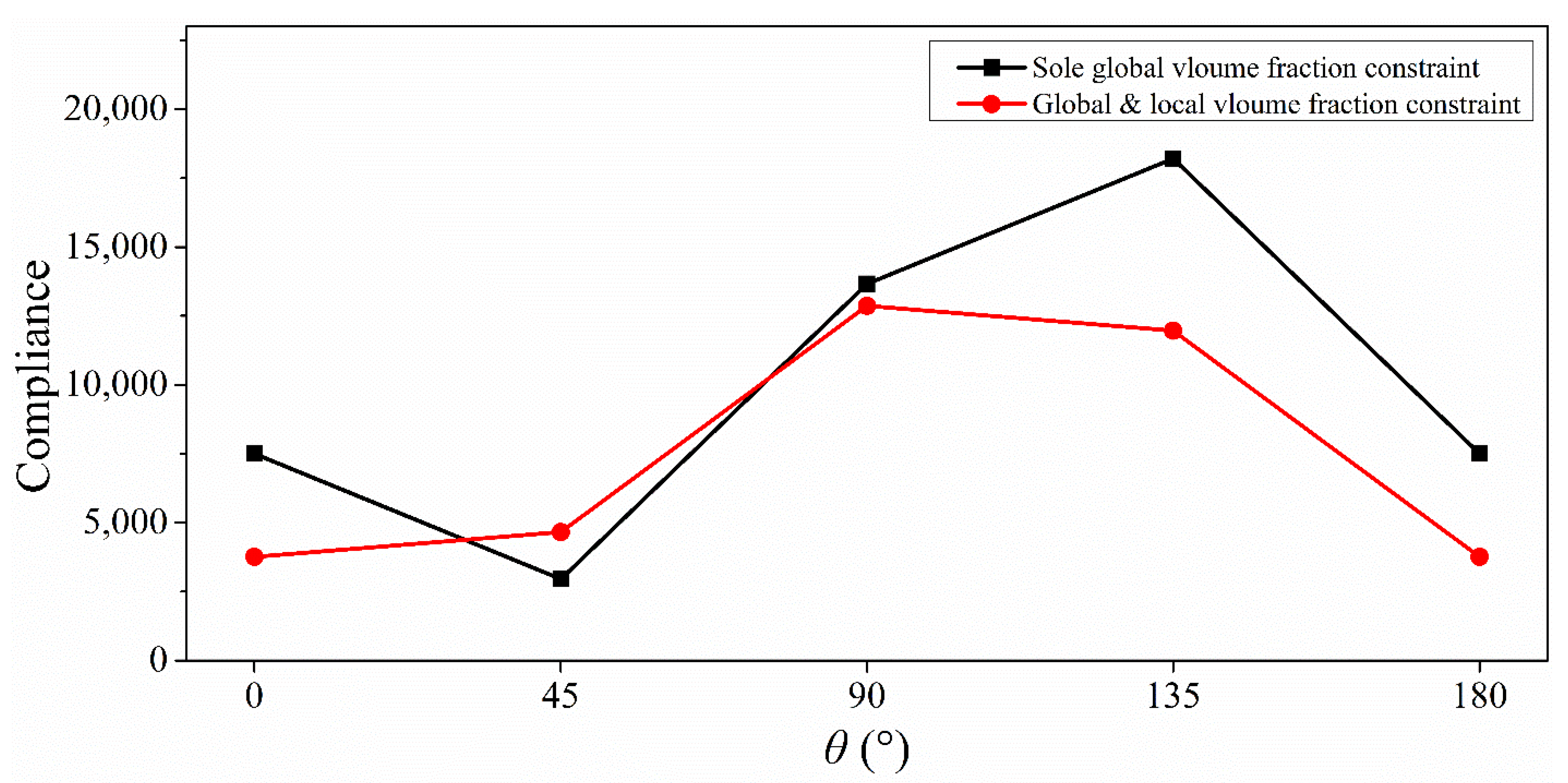
3.4. Example 4
3.5. Example 5
4. Discussion and Conclusions
Author Contributions
Funding
Data Availability Statement
Acknowledgments
Conflicts of Interest
References
- Osanov, M.; Guest, J.K. Topology optimization for architected materials design. Annu. Rev. Mater. Res. 2016, 46, 211–233. [Google Scholar] [CrossRef]
- Andreassen, E.; Lazarov, B.S.; Sigmund, O. Design of manufacturable 3D extremal elastic microstructure. Mech. Mater. 2015, 69, 1–10. [Google Scholar] [CrossRef] [Green Version]
- Clausen, A.; Wang, F.; Jensen, J.S.; Sigmund, O.; Lewis, J.A. Topology optimized architectures with programmable Poisso’s ratio over large deformations. Adv. Mater. 2015, 27, 5523–5527. [Google Scholar] [CrossRef] [PubMed] [Green Version]
- Chen, W.; Huang, X. Topological design of 3D chiral metamaterials based on couple-stress homogenization. J. Mech. Phys. Solids 2019, 131, 372–386. [Google Scholar] [CrossRef]
- Zhang, H.; Kang, Z.; Wang, Y.; Wu, W. Isotropic “Quasi-Fluid” Metameterial designed by topology optimization. Adv. Theory Simul. 2019, 3, 1900182. [Google Scholar] [CrossRef]
- Liu, J.; Chen, T.; Zhang, Y.; Wen, G.; Qing, Q.; Wang, H.; Xie, Y.M. On sound insulation of pyramidal lattice sandwich structure. Compos. Struct. 2019, 208, 385–394. [Google Scholar] [CrossRef] [Green Version]
- Meng, L.; Zhang, W.; Quan, D.; Shi, G.; Tang, L.; Hou, Y.; Breitkopf, P.; Zhu, J.; Gao, T. From topology optimization design to additive manufacturing: Today’s success and tomorrow’s roadmap. Struct. Multidiscip. Optim. 2020, 27, 805–830. [Google Scholar] [CrossRef]
- Rodrigues, H.; Guedes, J.M.; Bendsoe, M.P. Hierarchical optimization of material and structure. Struct. Multidiscip. Optim. 2002, 24, 1–10. [Google Scholar] [CrossRef]
- Xia, L.; Breitkopf, P. Concurrent topology optimization design of material and structure within FE2 nonlinear multiscale analysis framework. Comput. Methods Appl. Mech. Eng. 2014, 278, 524–542. [Google Scholar] [CrossRef]
- Da, D.; Cui, X.; Long, K.; Li, G.Y. Concurrent topological design of composite structures and the underlying multi-phase. Comput. Struct. 2017, 179, 1–14. [Google Scholar] [CrossRef] [Green Version]
- Long, K.; Dan, H.; Gu, X. Concurrent topology optimization of composite macrostructure and microstructure constructed by constituent phases of distinct Possion’s ratio for maximum frequency. Comput. Mater. Sci. 2017, 129, 194–201. [Google Scholar] [CrossRef]
- Jia, J.; Da, D.; Hu, J.; Yin, S. Crashworthness design of periodic cellular structures using topology optimization. Compos. Struct. 2021, 271, 114164. [Google Scholar] [CrossRef]
- Liu, L.; Yan, J.; Cheng, G. Optimum structure with homogeneous optimum truss-like material. Comput. Struct. 2008, 86, 1417–1425. [Google Scholar] [CrossRef]
- Li, H.; Luo, Z.; Gao, L.; Qin, Q. Topology optimization for concurrent design of structures with multi-patch microstructures by level sets. Comput. Methods Appl. Mech. Eng. 2018, 331, 536–561. [Google Scholar] [CrossRef] [Green Version]
- Wang, Y.; Chen, F.; Wang, M.Y. Concurrent design with connectable graded microstructure. Comput. Methods Appl. Mech. Eng. 2017, 317, 84–101. [Google Scholar] [CrossRef]
- Liu, P.; Kang, Z.; Luo, Y. Two-scale concurrent topology optimization of lattice structures with connectable microstructures. Addit. Manuf. 2020, 36, 101427. [Google Scholar]
- Li, Q.; Xu, R.; Wu, Q.; Liu, S. Topology optimization design of quasi-periodic cellular structures based on erode-dilate operators. Comput. Methods Appl. Mech. Eng. 2021, 377, 113720. [Google Scholar] [CrossRef]
- Zong, H.M.; Liu, H.; Ma, Q.P.; Tian, Y.; Zhou, M.D.; Wang, M.Y. VCTU level set method for topology optimization of functionally graded cellular structures. Comput. Methods Appl. Mech. Eng. 2019, 354, 487–505. [Google Scholar] [CrossRef]
- Liu, H.; Zong, H.; Shi, T.; Xia, Q. M-VCUT level set method for optimizing cellular structures. Comput. Methods Appl. Mech. Eng. 2020, 367, 113154. [Google Scholar] [CrossRef]
- Xia, Q.; Zong, H.; Shi, T.; Liu, H. Optimizing cellular structures through the M-VCUT level set method with microstructure mapping and high order cutting. Compos. Struct. 2021, 261, 113298. [Google Scholar] [CrossRef]
- Liu, C.; Du, Z.L.; Zhang, W.S.; Zhu, Y.C.; Guo, X. Additive manufacturing-oriented design of graded lattice structures through explicit topology optimization. J. Appl. Mech. 2017, 84, 081008. [Google Scholar] [CrossRef]
- Xue, D.; Zhu, Y.; Guo, X. Generation of smoothly-varying infill configurations from a continuous menu of cell patterns and the asymptotic analysis of its mechanical behavior. Comput. Methods Appl. Mech. Eng. 2020, 366, 113037. [Google Scholar] [CrossRef] [Green Version]
- Zhang, W.; Sun, S. Scale-related topology optimization of cellular materials and structures. Int. J. Numer. Methods Eng. 2006, 68, 993–1011. [Google Scholar] [CrossRef]
- Wu, Z.; Xia, L.; Wang, S.; Shi, T. Topology optimization of hierarchical lattice structures with substructing. Comput. Methods Appl. Mech. Eng. 2019, 345, 602–617. [Google Scholar] [CrossRef]
- Groen, J.P.; Sigmund, O. Homogenization-based topology optimization for high-resolution manufacturable microstructures. Int. J. Numer. Methods Eng. 2018, 113, 1148–1163. [Google Scholar] [CrossRef] [Green Version]
- Allaire, G.; Geoffroy-Donders, P.; Pantz, O. Topology optimization of modulated and oriented periodic microstructure by the homogenization method. Comput. Math. Appl. 2019, 78, 2197–2229. [Google Scholar] [CrossRef] [Green Version]
- Lee, J.; Kwon, C.; Yoo, J.; Min, S.; Nomura, T.; Dede, E.M. Design of spatially-varying orthotropic infill structures using multiscale topology optimization and explicit de-homogenization. Addit. Manuf. 2021, 40, 101920. [Google Scholar]
- Wu, J.; Sigmund, O.; Groen, J.P. Topology optimization of multi-scale structures: A review. Struct. Multidiscip. Optim. 2021, 63, 1455–1480. [Google Scholar] [CrossRef]
- Guest, J.K.; Prévost, J.H. A penalty function for enforcing maximum length scale in topology optimization. In Proceedings of the 11th AIAA/ISSMO Multidisciplinary Analysis and Optimization Conference, Portsmouth, VA, USA, 6–8 September 2006. [Google Scholar]
- Guest, J.K. Imposing maximum length in topology optimization. Struct. Multidiscip. Optim. 2009, 37, 463–473. [Google Scholar] [CrossRef]
- Carstensen, J.V.; Guest, J.K. Projection-based two-phase minimum and maximum length scale control in topology optimization. Struct. Multidiscip. Optim. 2018, 58, 1845–1860. [Google Scholar] [CrossRef]
- Zhao, Z.L.; Zhou, S.; Feng, X.Q.; Xie, Y.M. On the internal architecture of emergent plants. J. Mech. Phys. Solids 2018, 119, 224–239. [Google Scholar] [CrossRef]
- Qiu, W.; Jin, P.; Jin, S.; Wang, C.; Xia, L.; Zhu, J.; Shi, T. An evolutionary design approach to shell-infill structures. Addit. Manuf. 2020, 34, 101382. [Google Scholar] [CrossRef]
- Wu, J.; Aage, N.; Westermann, R.; Simgund, O. Infill optimization for additive manufacturing—approaching bone-like porous structures. IEEE Trans. Vis. Comput. Graph 2018, 24, 1127–1140. [Google Scholar] [CrossRef] [Green Version]
- Wu, J.; Clausen, A.; Simgund, O. Minimum compliance topology optimization of shell-infill composites for additive manufacturing. Comput. Methods Appl. Mech. Eng. 2017, 326, 358–375. [Google Scholar] [CrossRef] [Green Version]
- Liu, Y.; Zhou, M.; Wei, C.; Lin, Z. Topology optimization of self-supporting infill structures. Struct. Multidiscip. Optim. 2021, 63, 2289–2304. [Google Scholar] [CrossRef]
- Yan, S.; Wang, F.; Sigmund, O. On the non-optimality of tree structures for heat conduction. Int. J. Heat Mass Transf. 2018, 122, 660–680. [Google Scholar] [CrossRef] [Green Version]
- Li, H.; Gao, L.; Li, H.; Tong, H. Spatial-varying multi-phase infill design using density-based topology optimization. Comput. Methods Appl. Mech. Eng. 2020, 372, 113354. [Google Scholar] [CrossRef]
- Liang, Y.; Cheng, G. Topology optimization via sequential integer programming and Canonical relaxation algorithm. Comput. Methods Appl. Mech. Eng. 2019, 348, 64–96. [Google Scholar] [CrossRef]
- Chen, L.; Liu, H.; Chu, X.; Wang, J. Functionally graded cellular structure design using the subdomain level set method with local volume constraints. Comput. Modeling Eng. Sci. 2021, 128, 1197–1218. [Google Scholar] [CrossRef]
- Lazarov, B.S.; Wang, F. Maximum length scale in density based topology optimization. Comput. Methods Appl. Mech. Eng. 2017, 318, 826–844. [Google Scholar] [CrossRef] [Green Version]
- Dou, S. A projection approach for topology optimization of porous structures through implicit local volume control. Struct. Multidiscip. Optim. 2020, 62, 835–850. [Google Scholar] [CrossRef]
- Fernández, E.; Collet, M.; Alarcón, P.; Bauduin, S.; Duysinx, P. An aggregation strategy of maximum size constraints in density-based topology optimization. Struct. Multidiscip. Optim. 2019, 60, 2113–2130. [Google Scholar] [CrossRef]
- Clausen, A.; Aage, N.; Sigmund, O. Exploiting additive manufacturing infill in topology optimization for improved buckling load. Engineering 2016, 2, 250–257. [Google Scholar] [CrossRef] [Green Version]
- Silva, G.A.; Beck, A.T.; Sigmund, O. Topology optimization of compliant mechanisms with stress constraints and manufacturing error robustness. Comput. Methods Appl. Mech. Eng. 2019, 354, 397–421. [Google Scholar] [CrossRef]
- Silva, G.A.; Aage, N.; Beck, A.T.; Sigmund, O. Three-dimensional manufacturing tolerant topology optimization with hundreds of millions of local stress constraints. Int. J. Numer Methods Eng. 2021, 122, 548–578. [Google Scholar] [CrossRef]
- Senhora, F.V.; Giraldo-Londono, O.; Menezes, I.F.M.; Paulino, G.H. Topology optimization with local stress constraints: A stress aggregation-free approach. Struct. Multidiscip. Optim. 2020, 62, 1639–1668. [Google Scholar] [CrossRef]
- Giraldo-Londono, O.; Paulino, G.H. Polystress: A Matlab implementation for local-stress constrained topology optimization using the augmented Lagrangian method. Struct. Multidiscip. Optim. 2021, 63, 2065–2097. [Google Scholar] [CrossRef]
- Wang, F.; Lazarov, B.S.; Sigmund, O. On projection methods, convergence and robust formulations in topology optimization. Struct. Multidiscip. Optim. 2011, 43, 767–784. [Google Scholar] [CrossRef]
- Bruns, T.E.; Tortorelli, D.A. Topology optimization of non-linear elastic structures and compliant mechanisms. Comput. Methods Appl. Mech. Eng. 2001, 190, 3443–3459. [Google Scholar] [CrossRef]
- Bounrdin, B. Filters in topology optimization. Int. J. Numer. Methods Eng. 2001, 50, 2143–2158. [Google Scholar] [CrossRef]
- Sigmund, O.; Maute, K. Topology optimization approaches. Struct. Multidiscip. Optim. 2013, 48, 1030–1055. [Google Scholar] [CrossRef]
- Svanberg, K. The method of moving asymptotes—a new method for structural optimization. Int. J. Numer. Methods Eng. 1987, 24, 359–373. [Google Scholar] [CrossRef]
- Long, K.; Wang, X.; Liu, H. Stress-constrained topology optimization of continuum structures subject to harmonic force excitation using sequential quadratic programming. Struct. Multidiscip. Optim. 2019, 59, 1747–1759. [Google Scholar] [CrossRef]
- Long, K.; Gu, C.; Wang, X.; Liu, J.; Du, Y.; Chen, Z.; Saeed, N. A novel minimum weight formulation of topology optimization implemented with reanalysis approach. Int. J. Numer. Methods Eng. 2019, 120, 567–579. [Google Scholar] [CrossRef]
- Wei, P.; Li, Z.; Li, X.; Wang, M.Y. An 88-line MATLAB code for the parameterized level set method based topology optimization using radial basis function. Struct. Multidiscip. Optim. 2018, 58, 831–849. [Google Scholar] [CrossRef]
- Rashid, R.; Masood, S.; Ruan, D.; Palanisamy, S.; Huang, X.; Rahman, R. Topology optimisation of additively manufactured lattice beams for three-point bending test. In Proceedings of the 29th Annual International Solid Freeform Fabrication Symposium—An Additive Manufacturing Conference, Austin, TX, USA, 13–15 August 2018; pp. 635–645. [Google Scholar]
- Xiao, Z.; Yang, Y.; Xiao, R.; Bai, Y.; Song, C.; Wang, D. Evaluation of topology-optimized lattice structures manufactured via selective laser melting. Mater. Design 2018, 143, 27–37. [Google Scholar] [CrossRef]
- Andreassen, E.; Clausen, A.; Schevenels, M.; Lazarov, B.; Sigmund, O. Efficient topology optimization in MATLAB using 88 lines of code. Struct. Multidiscip. Optim. 2011, 43, 1–16. [Google Scholar] [CrossRef] [Green Version]


Publisher’s Note: MDPI stays neutral with regard to jurisdictional claims in published maps and institutional affiliations. |
© 2021 by the authors. Licensee MDPI, Basel, Switzerland. This article is an open access article distributed under the terms and conditions of the Creative Commons Attribution (CC BY) license (https://creativecommons.org/licenses/by/4.0/).
Share and Cite
Long, K.; Chen, Z.; Zhang, C.; Yang, X.; Saeed, N. An Aggregation-Free Local Volume Fraction Formulation for Topological Design of Porous Structure. Materials 2021, 14, 5726. https://doi.org/10.3390/ma14195726
Long K, Chen Z, Zhang C, Yang X, Saeed N. An Aggregation-Free Local Volume Fraction Formulation for Topological Design of Porous Structure. Materials. 2021; 14(19):5726. https://doi.org/10.3390/ma14195726
Chicago/Turabian StyleLong, Kai, Zhuo Chen, Chengwan Zhang, Xiaoyu Yang, and Nouman Saeed. 2021. "An Aggregation-Free Local Volume Fraction Formulation for Topological Design of Porous Structure" Materials 14, no. 19: 5726. https://doi.org/10.3390/ma14195726