
Cause and Mitigation of Lithium-Ion Battery Failure—A Review

 ,
,  , , ,
, , ,  and
and 
Abstract
:
1. Introduction
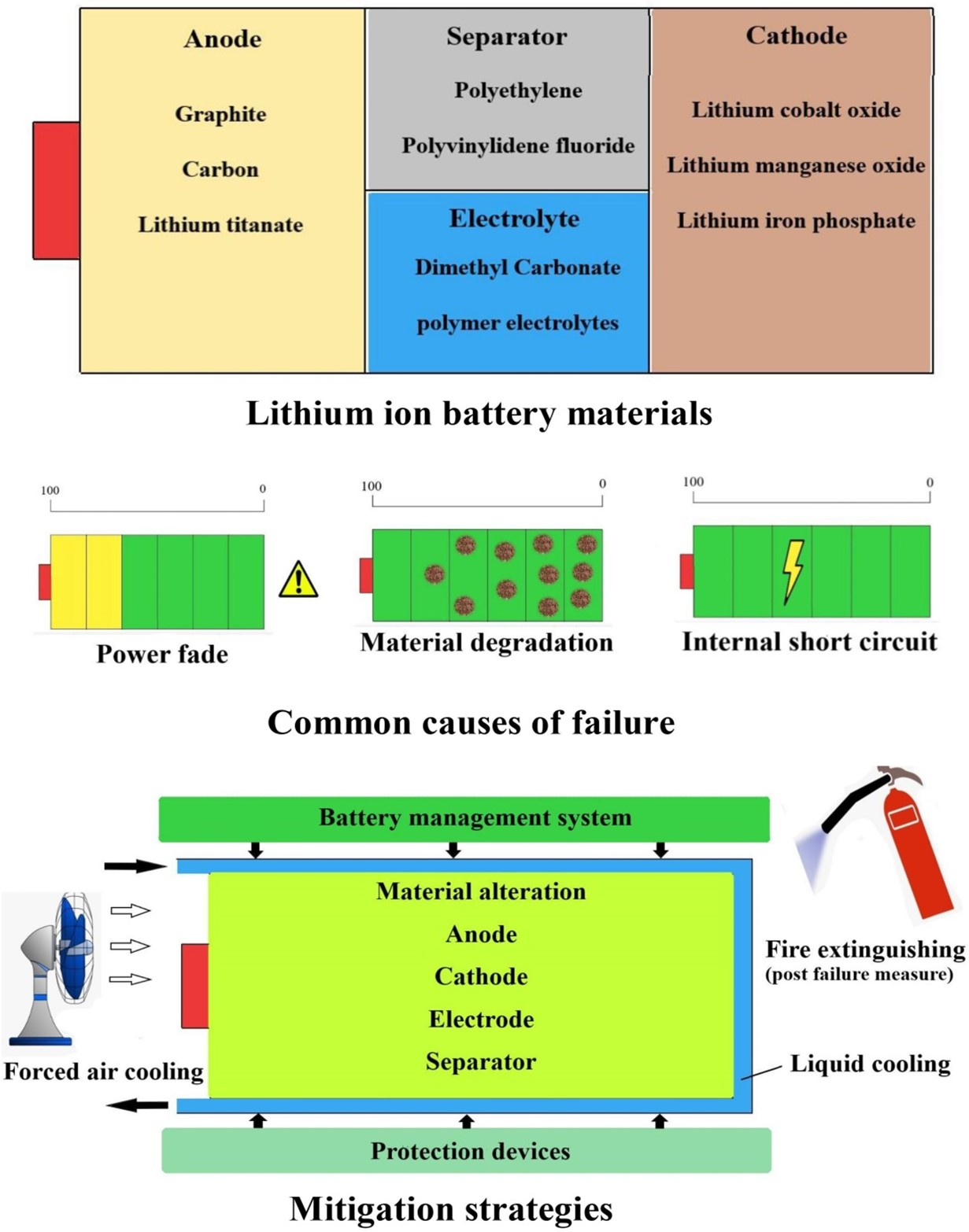
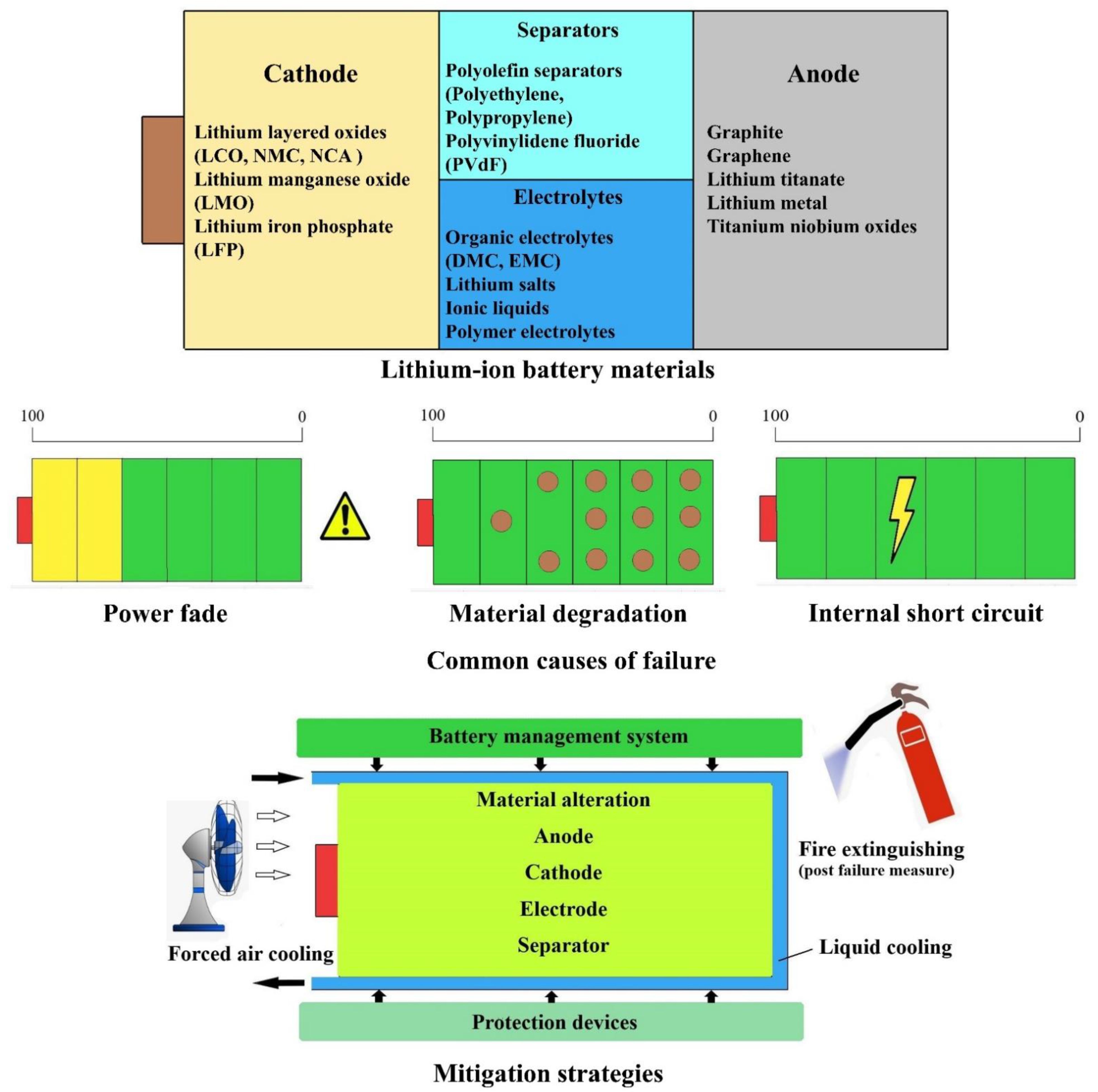
2. LiBs Materials
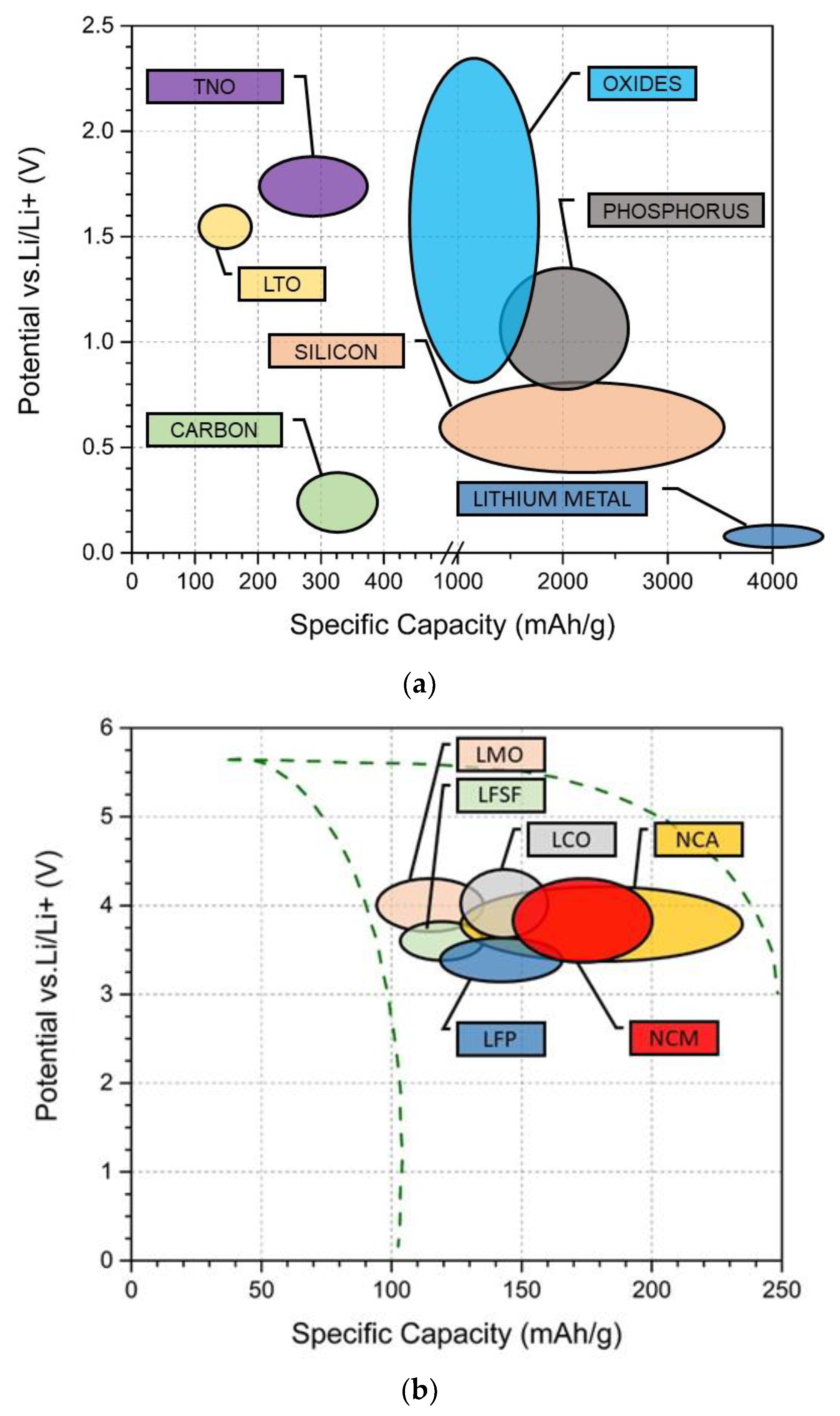
2.1. Anode
2.2. Cathode
2.3. Electrolytes
2.4. Separators
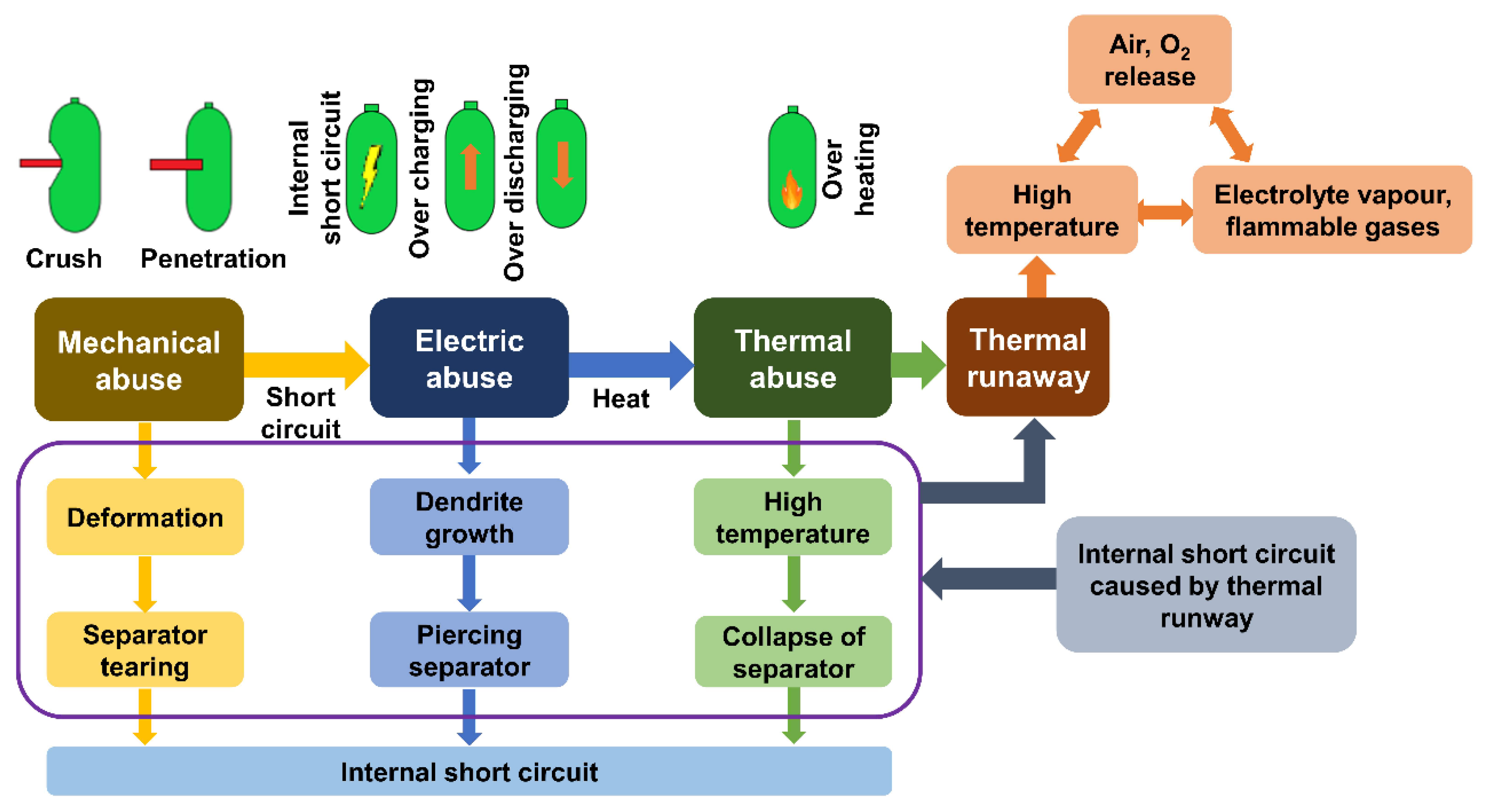
3. Mechanism of Failure in LIB
3.1. The Active Material in Anode
3.2. Cathode Material
3.3. Electrolyte
3.4. Separators
3.5. Current Collectors
3.6. Cell Tabs and Casing
4. Failure Modes of LiBs
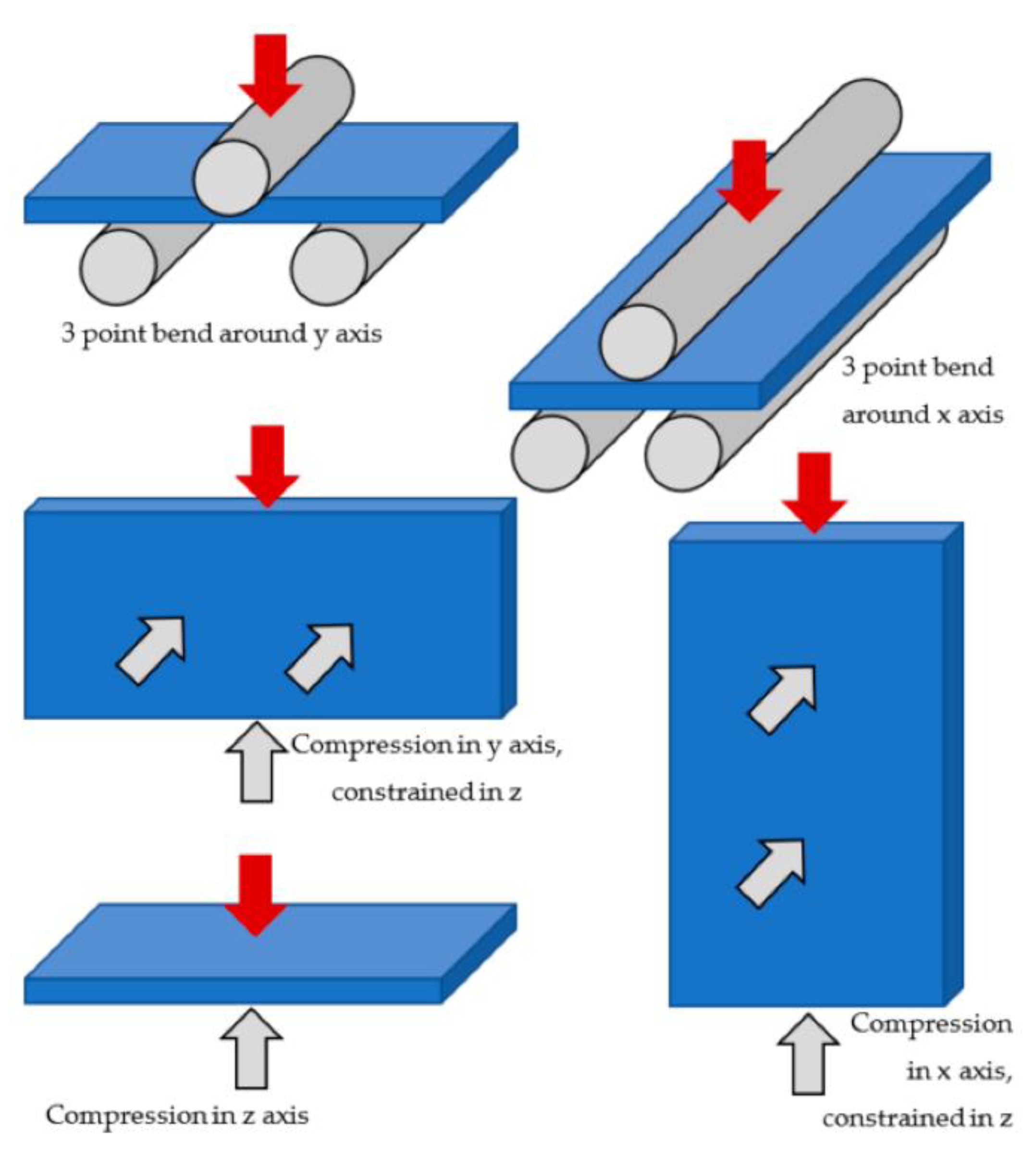
4.1. Mechanical Mode
4.1.1. Cylindrical Battery
4.1.2. Prismatic Battery
4.1.3. Pouch Cells
4.2. Electric Mode
4.3. Thermal Mode
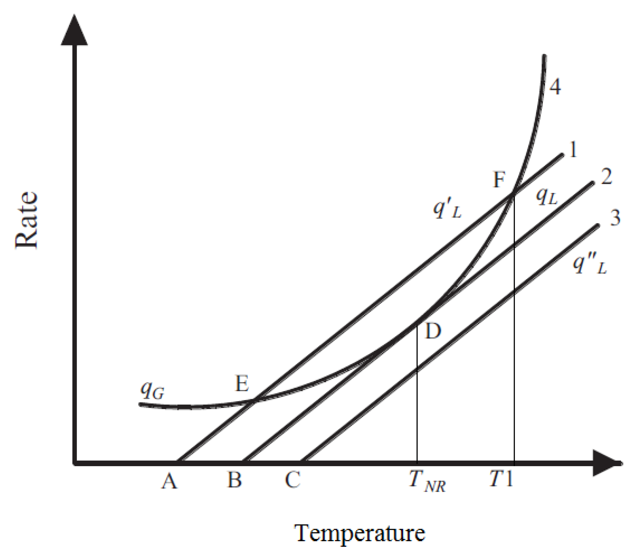
4.3.1. Governing Equations for Thermal Runaway
Anode
Cathode
Electrolyte
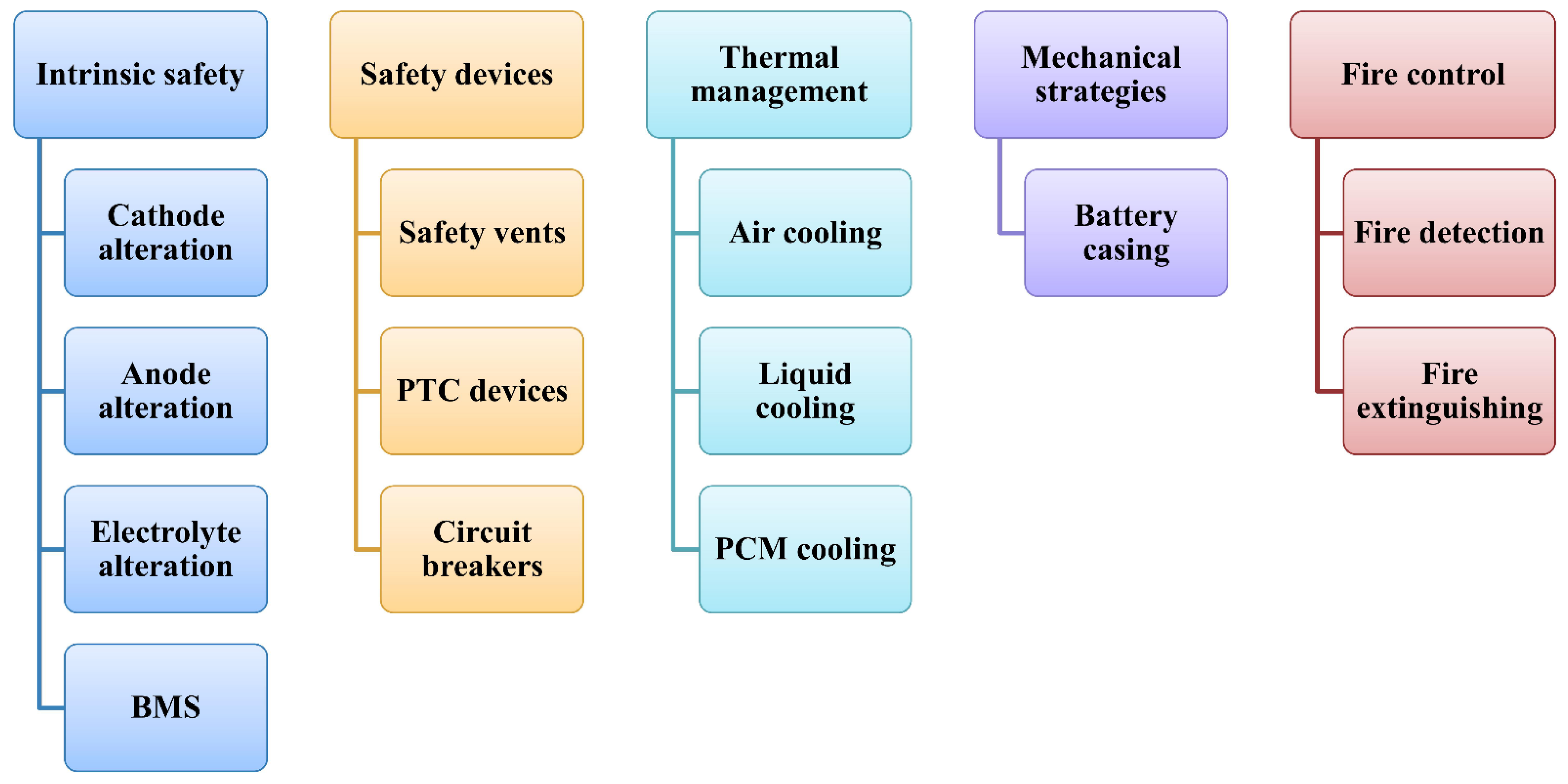
5. Mitigation Strategies
5.1. Innate Safety Strategies
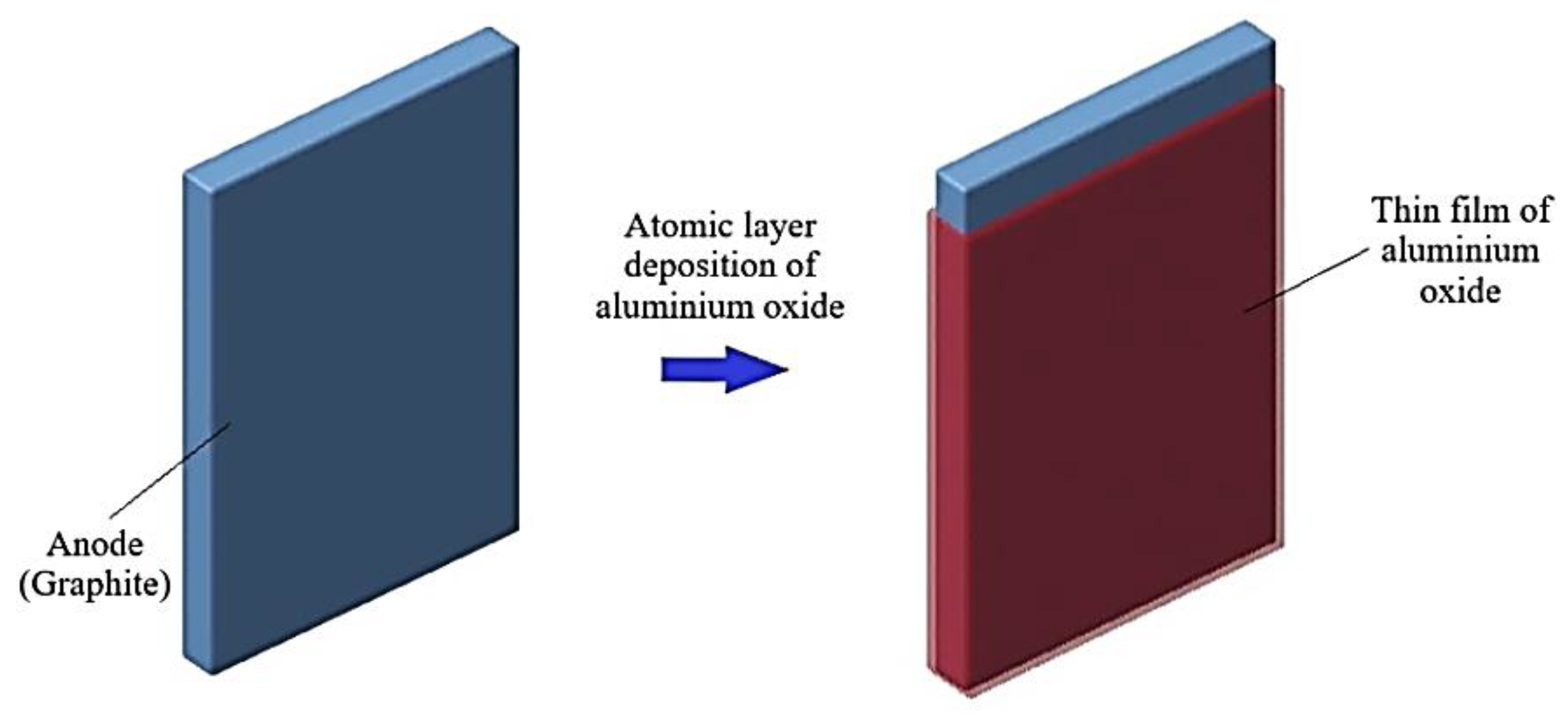
5.1.1. Anode Alteration (Protection)
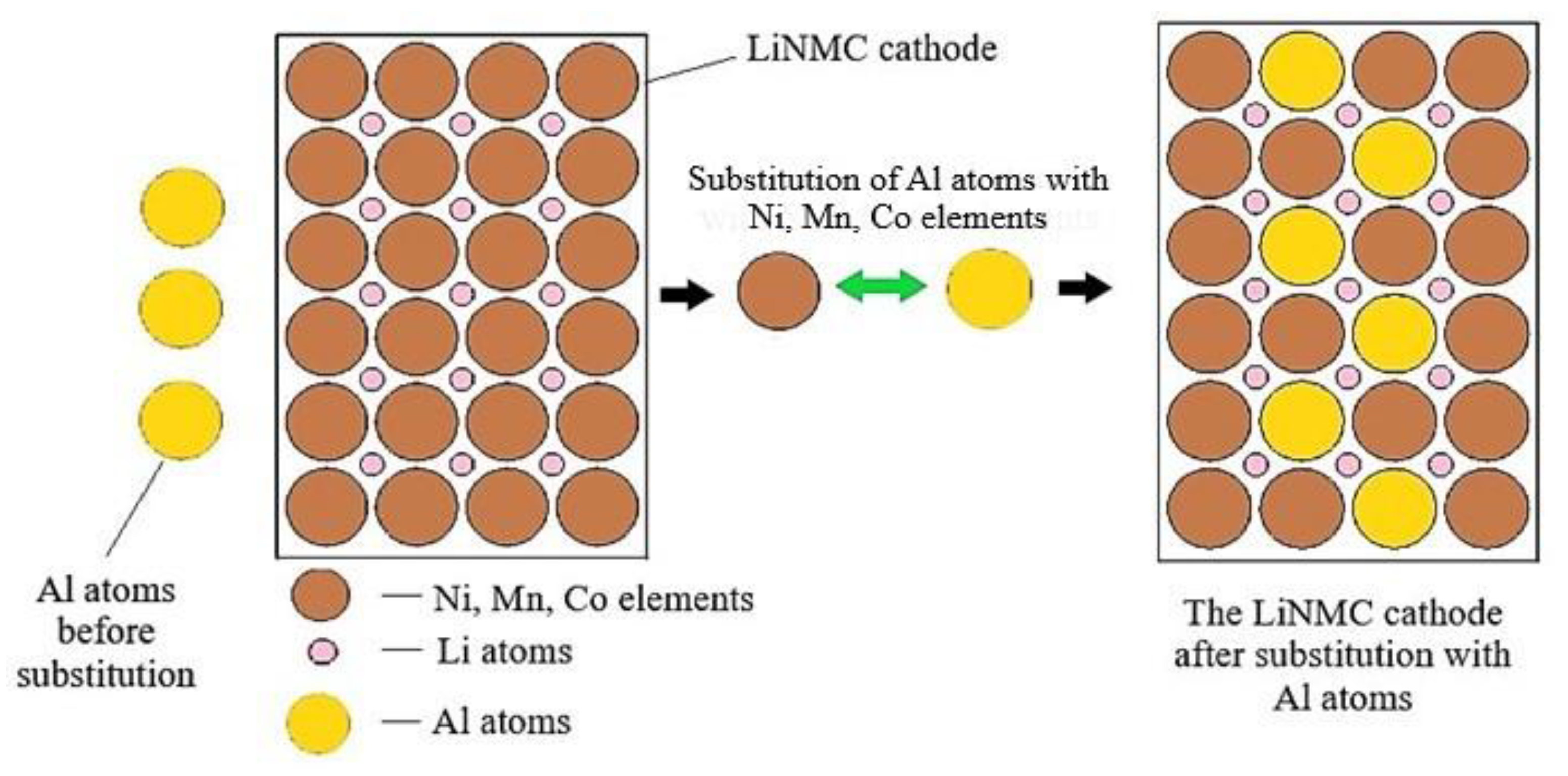
5.1.2. Cathode Alteration
5.1.3. Electrolyte Alteration
5.1.4. Separators
5.1.5. Battery Management Systems
5.2. Protective Devices
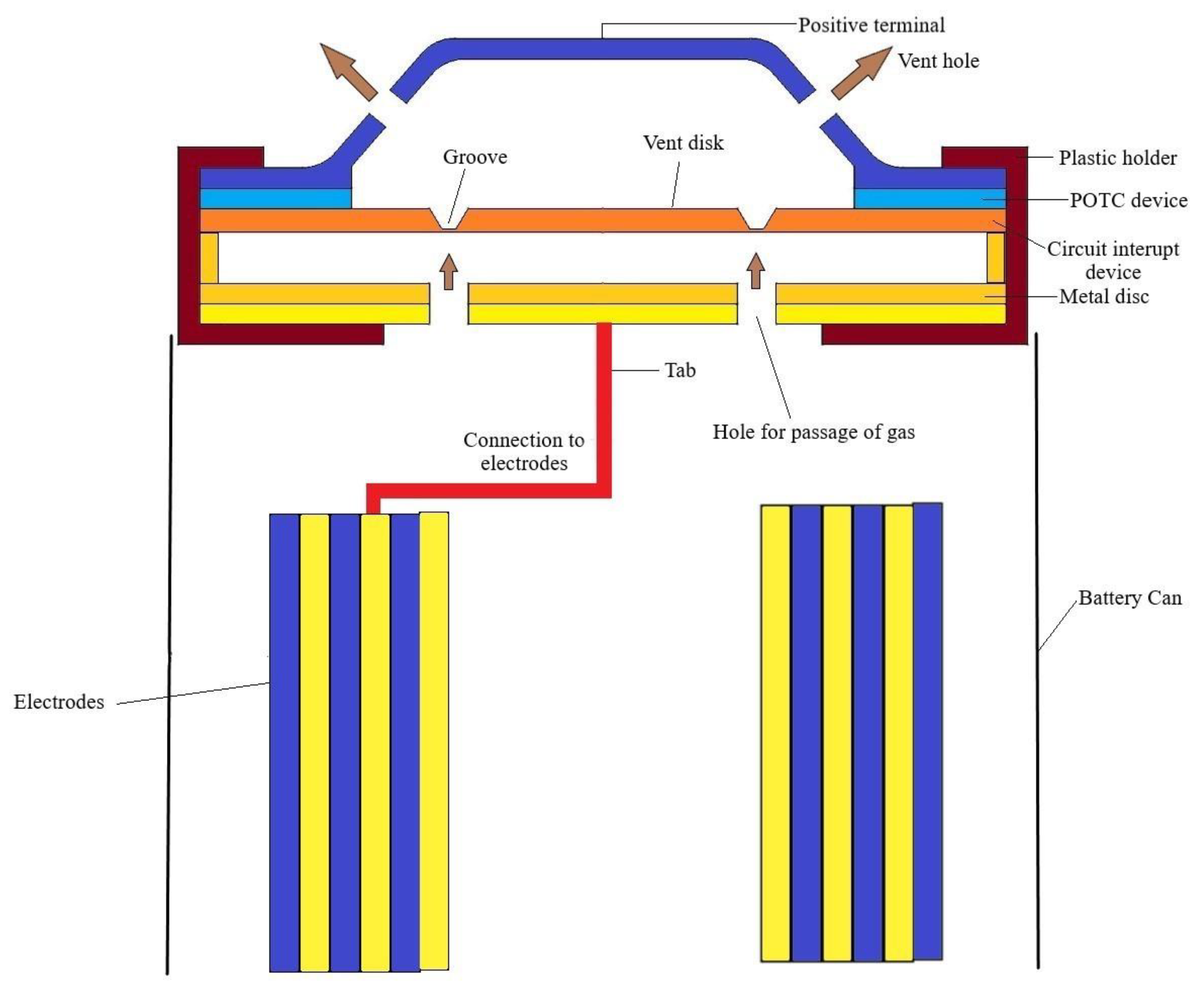
5.2.1. Protection Vents
5.2.2. Positive Thermal Coefficient Device (POTC)
5.2.3. Other Circuit Cut off Devices
5.3. Thermal Management
5.3.1. Air Cooling of LiBs
5.3.2. Liquid Cooling of LiBs
5.3.3. Phase Change Material (PCM) Cooling of LiBs
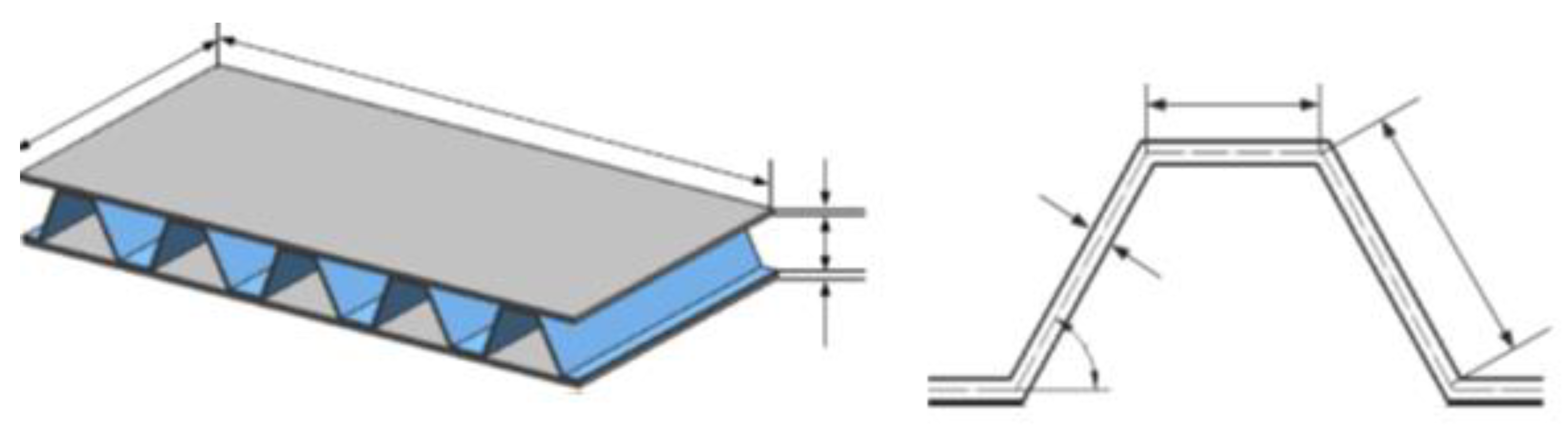
5.4. Mechanical Mitigation Strategies
5.5. Fire Control
5.5.1. Fire Diagnosis Device
5.5.2. Fire Extinguishing
6. Summary
Author Contributions
Funding
Institutional Review Board Statement
Informed Consent Statement
Data Availability Statement
Acknowledgments
Conflicts of Interest
Abbreviations
| ALD | Atomic Layer Deposition |
| ARC | Accelerated Rate Calorimetry |
| BMS | Battery Management System |
| BRAS | Blast Resistant Adaptive Sandwich |
| BTMS | Battery Thermal Management System |
| DEC | Diethyl Carbonate |
| DMC | Dimethyl Carbonate |
| DOD | Depth of Discharge |
| DSC | Differential Scanning Calorimetry |
| EC | Ethylene Carbonate |
| EMC | Ethylmethyl Carbonate |
| FIB | Focused Ion Beam |
| FMEA | Failure Mode Effects Analysis |
| FMMEA | Failure Mode Methods Effects Analysis |
| FTIR | Fourier Transform Infrared Spectroscopy |
| ISCs | Internal Short Circuits |
| LCO | Lithium Cobalt Oxide |
| LFP | Lithium Iron Phosphate |
| LiBs | Lithium-ion batteries |
| LMO | Lithium Manganese Oxide |
| LTO | Lithium Titanate |
| NavTruss | Navy Truss |
| NCA | Lithium Nickel Cobalt Aluminium |
| NMC | Lithium Nickel Manganese Cobalt |
| NMR | Nuclear Magnetic Resonance |
| PAN | Polyacrylonitrile |
| PBT | Polybutylene Terephthalate |
| PC | Propylene Carbonate |
| PE | Polyethylene |
| PET | Polyethylene Terephthalate |
| PoE | Polymer Electrolyte |
| POF | Physics of Failure |
| POTC | Positive Thermal Coefficient Device |
| PRCM | Protection Circuit Modules |
| PP | Polypropylene |
| PCM | Phase Change Material |
| PVdF | Polyvinylidene Fluoride |
| SEI | Solid Electrolyte Interface |
| SEM | Scanning Electron Microscope |
| SOA | Safe Operating Area |
| SOC | State of Charge |
| SOF | State of Function |
| SOH | State of Health |
| TGA | Thermo-Gravimetric Analysis |
| ZS | Zero Strain |
References
- Sanders, M. Lithium-ion battery raw material supply and demand 2016–2025. In Proceedings of the Advanced Automotive Battery Conference, San Francisco, CA, USA, 19–22 June 2017; pp. 162–181. [Google Scholar]
- Curry, C. Lithium-ion battery costs and market. Bloom. New Energy Financ. 2017, 5, 4–6. [Google Scholar]
- Nishi, Y. Lithium ion secondary batteries; Past 10 years and the future. J. Power Source 2001, 100, 101–106. [Google Scholar] [CrossRef]
- Julien, C.; Mauger, A.; Vijh, A.; Zaghib, K. Lithium Batteries: Science and Technology; Springer International Publishing: Cham, Switzerland, 2015; ISBN 9783319191089. [Google Scholar]
- Williard, N.; He, W.; Osterman, M.; Pecht, M. Reliability and failure analysis of Lithium Ion batteries for electronic systems. In Proceedings of the 2012 13th International Conference on Electronic Packaging Technology & High Density Packaging, Guilin, China, 13–16 August 2012; pp. 1051–1055. [Google Scholar] [CrossRef]
- Liu, G.; Ouyang, M.; Lu, L.; Li, J.; Han, X. Analysis of the heat generation of lithium-ion battery during charging and discharging considering different influencing factors. J. Therm. Anal. Calorim. 2014, 116, 1001–1010. [Google Scholar] [CrossRef]
- Bandhauer, T.M.; Garimella, S.; Fuller, T.F. A Critical Review of Thermal Issues in Lithium-Ion Batteries. J. Electrochem. Soc. 2011, 158, R1. [Google Scholar] [CrossRef]
- Liu, B.; Jia, Y.; Yuan, C.; Wang, L.; Gao, X.; Yin, S.; Xu, J. Safety issues and mechanisms of lithium-ion battery cell upon mechanical abusive loading: A review. Energy Storage Mater. 2020, 24, 85–112. [Google Scholar] [CrossRef]
- Liu, K.; Liu, Y.; Lin, D.; Pei, A.; Cui, Y. Materials for lithium-ion battery safety. Sci. Adv. 2018, 4, eaas9820. [Google Scholar] [CrossRef] [Green Version]
- Lin, X.; Hao, X.; Liu, Z.; Jia, W. Health conscious fast charging of Li-ion batteries via a single particle model with aging mechanisms. J. Power Source 2018, 400, 305–316. [Google Scholar] [CrossRef]
- Ma, S.; Jiang, M.; Tao, P.; Song, C.; Wu, J.; Wang, J.; Deng, T.; Shang, W. Temperature effect and thermal impact in lithium-ion batteries: A review. Prog. Nat. Sci. Mater. Int. 2018, 28, 653–666. [Google Scholar] [CrossRef]
- Aris, A.M.; Shabani, B. An Experimental Study of a Lithium Ion Cell Operation at Low Temperature Conditions. Energy Procedia 2017, 110, 128–135. [Google Scholar] [CrossRef]
- Liu, B.; Jia, Y.; Li, J.; Yin, S.; Yuan, C.; Hu, Z.; Wang, L.; Li, Y.; Xu, J. Safety issues caused by internal short circuits in lithium-ion batteries. J. Mater. Chem. A 2018, 6, 21475–21484. [Google Scholar] [CrossRef]
- Sheikh, M.; Elmarakbi, A.; Rehman, S. A combined experimental and simulation approach for short circuit prediction of 18650 lithium-ion battery under mechanical abuse conditions. J. Energy Storage 2020, 32, 101833. [Google Scholar] [CrossRef]
- Reddy, M.V.; Julien, C.M.; Mauger, A.; Zaghib, K. Sulfide and oxide inorganic solid electrolytes for all-solid-state li batteries: A review. Nanomaterials 2020, 10, 1606. [Google Scholar] [CrossRef]
- Reddy, M.V.; Mauger, A.; Julien, C.M.; Paolella, A.; Zaghib, K. Brief history of early lithium-battery development. Materials 2020, 13, 1884. [Google Scholar] [CrossRef] [Green Version]
- Reddy, M.V.; Subba Rao, G.V.; Chowdari, B.V.R. Metal oxides and oxysalts as anode materials for Li ion batteries. Chem. Rev. 2013, 113, 5364–5457. [Google Scholar] [CrossRef]
- Tarascon, J.M.; Armand, M. Issues and challenges facing rechargeable lithium batteries. In Materials for Sustainable Energy. A Collection of Peer-Reviewed Research and Review Articles from Nature Publishing Group; World Scientific Publishing Co. Pte. Ltd.: Singapore, 2011; pp. 171–179. [Google Scholar] [CrossRef]
- Kato, Y.; Ogumi, Z.; Perlado Martín, J.M. Lithium-Ion Batteries: Overview, Simulation, and Diagnostics; Jenny Stanford Publishing: Singapore, 2019. [Google Scholar] [CrossRef]
- Lu, J.; Chen, Z.; Pan, F.; Cui, Y.; Amine, K. High-Performance Anode Materials for Rechargeable Lithium-Ion Batteries. Electrochem. Energy Rev. 2018, 1, 35–53. [Google Scholar] [CrossRef]
- Wu, Y.; Reddy, M.V.; Chowdari, B.V.R.; Ramakrishna, S. Electrochemical studies on electrospun Li(Li1/3Ti5/3)O4 grains as an anode for Li-ion batteries. Electrochim. Acta 2012, 67, 33–40. [Google Scholar] [CrossRef]
- Yuan, T.; Soule, L.; Zhao, B.; Zou, J.; Yang, J.; Liu, M.; Zheng, S. Recent Advances in Titanium Niobium Oxide Anodes for High-Power Lithium-Ion Batteries. Energy Fuels 2020, 34, 13321–13334. [Google Scholar] [CrossRef]
- Eftekhari, A. Future Lithium-Ion Batteries; Royal Society of Chemistry: London, UK, 2019. [Google Scholar]
- Kaskhedikar, N.A.; Maier, J. Lithium storage in carbon nanostructures. Adv. Mater. 2009, 21, 2664–2680. [Google Scholar] [CrossRef]
- Wang, G.; Shen, X.; Yao, J.; Park, J. Graphene nanosheets for enhanced lithium storage in lithium ion batteries. Carbon 2009, 47, 2049–2053. [Google Scholar] [CrossRef]
- Liu, X.M.; Huang, Z.d.; Oh, S.w.; Zhang, B.; Ma, P.C.; Yuen, M.M.F.; Kim, J.K. Carbon nanotube (CNT)-based composites as electrode material for rechargeable Li-ion batteries: A review. Compos. Sci. Technol. 2012, 72, 121–144. [Google Scholar] [CrossRef]
- Zhao, B.; Ran, R.; Liu, M.; Shao, Z. A comprehensive review of Li4Ti5O12-based electrodes for lithium-ion batteries: The latest advancements and future perspectives. Mater. Sci. Eng. R Rep. 2015, 98, 1–71. [Google Scholar] [CrossRef]
- Nitta, N.; Wu, F.; Lee, J.T.; Yushin, G. Li-ion battery materials: Present and future. Mater. Today 2015, 18, 252–264. [Google Scholar] [CrossRef]
- Korthauer, R. Lithium-Ion Batteries: Basics and Applications; Springer: Berlin/Heidelberg, Germany, 2018; ISBN 9783662530719. [Google Scholar]
- Kasnatscheew, J.; Streipert, B.; Röser, S.; Wagner, R.; Cekic Laskovic, I.; Winter, M. Determining oxidative stability of battery electrolytes: Validity of common electrochemical stability window (ESW) data and alternative strategies. Phys. Chem. Chem. Phys. 2017, 19, 16078–16086. [Google Scholar] [CrossRef] [PubMed]
- Obrovac, M.N.; Chevrier, V.L. Alloy negative electrodes for Li-ion batteries. Chem. Rev. 2014, 114, 11444–11502. [Google Scholar] [CrossRef] [PubMed]
- Xin, F.; Whittingham, M.S. Challenges and Development of Tin-Based Anode with High Volumetric Capacity for Li-Ion Batteries. Electrochem. Energy Rev. 2020, 3, 643–655. [Google Scholar] [CrossRef]
- Zuo, X.; Zhu, J.; Müller-Buschbaum, P.; Cheng, Y.J. Silicon based lithium-ion battery anodes: A chronicle perspective review. Nano Energy 2017, 31, 113–143. [Google Scholar] [CrossRef]
- Qian, J.; Henderson, W.A.; Xu, W.; Bhattacharya, P.; Engelhard, M.; Borodin, O.; Zhang, J.G. High rate and stable cycling of lithium metal anode. Nat. Commun. 2015, 6, 7362. [Google Scholar] [CrossRef] [Green Version]
- Lin, D.; Liu, Y.; Cui, Y. Reviving the lithium metal anode for high-energy batteries. Nat. Nanotechnol. 2017, 12, 194–206. [Google Scholar] [CrossRef]
- Cheng, X.B.; Zhang, R.; Zhao, C.Z.; Zhang, Q. Toward Safe Lithium Metal Anode in Rechargeable Batteries: A Review. Chem. Rev. 2017, 117, 10403–10473. [Google Scholar] [CrossRef]
- Armand, M.B. The iron cyanide bronzes. Mater. Res. Bull. 1972, 7, 101–107. [Google Scholar] [CrossRef]
- Mizushima, K.; Jones, P.C.; Wiseman, P.J.; Goodenough, J.B. LixCoO2 (0 < x < −1): A new cathode material for batteries of high energy density. Mater. Res. Bull. 1980, 15, 783–789. [Google Scholar] [CrossRef]
- Akimoto, J.; Gotoh, Y.; Oosawa, Y. Synthesis and Structure Refinement of LiCoO2 Single Crystals. J. Solid State Chem. 1998, 141, 298–302. [Google Scholar] [CrossRef]
- Reddy, T.B. Linden’s Handbook of Batteries; McGraw-Hill: New York, NY, USA, 2011; Volume 4. [Google Scholar]
- Kasnatscheew, J.; Evertz, M.; Kloepsch, R.; Streipert, B.; Wagner, R.; Cekic Laskovic, I.; Winter, M. Learning from Electrochemical Data: Simple Evaluation and Classification of LiMO2-type-based Positive Electrodes for Li-Ion Batteries. Energy Technol. 2017, 5, 1670–1679. [Google Scholar] [CrossRef]
- Ohzuku, T.; Ueda, A.; Nagayama, M.; Iwahoshi, Y.; Komori, H. Comparative study of LiCoO2, LiNi12Co12O2 and LiNiO2 for 4 volt secondary lithium cells. Electrochim. Acta 1993, 38, 1159–1167. [Google Scholar] [CrossRef]
- Du Pasquier, A.; Plitz, I.; Menocal, S.; Amatucci, G. A comparative study of Li-ion battery, supercapacitor and nonaqueous asymmetric hybrid devices for automotive applications. J. Power Source 2003, 115, 171–178. [Google Scholar] [CrossRef]
- Doughty, D.; Roth, E.P. A general discussion of Li Ion battery safety. Electrochem. Soc. Interface 2012, 21, 37–44. [Google Scholar] [CrossRef] [Green Version]
- Ohzuku, T.; Makimura, Y. Layered lithium insertion material of LiCo1/3Ni1/3Mn1/3O2 for lithium-ion batteries. Chem. Lett. 2001, 30, 642–643. [Google Scholar] [CrossRef]
- Whittingham, M.S. Lithium batteries and cathode materials. Chem. Rev. 2004, 104, 4271–4301. [Google Scholar] [CrossRef]
- Bloom, I.; Jones, S.A.; Battaglia, V.S.; Henriksen, G.L.; Christophersen, J.P.; Wright, R.B.; Ho, C.D.; Belt, J.R.; Motloch, C.G. Effect of cathode composition on capacity fade, impedance rise and power fade in high-power, lithium-ion cells. J. Power Source 2003, 124, 538–550. [Google Scholar] [CrossRef]
- Myung, S.T.; Amine, K.; Sun, Y.K. Surface modification of cathode materials from nano-to microscale for rechargeable lithium-ion batteries. J. Mater. Chem. 2010, 20, 7074–7095. [Google Scholar] [CrossRef]
- Thackeray, M.M.; David, W.I.F.; Bruce, P.G.; Goodenough, J.B. Lithium insertion into manganese spinels. Mater. Res. Bull. 1983, 18, 461–472. [Google Scholar] [CrossRef]
- Gummow, R.J.; de Kock, A.; Thackeray, M.M. Improved capacity retention in rechargeable 4 V lithium/lithium-manganese oxide (spinel) cells. Solid State Ion. 1994, 69, 59–67. [Google Scholar] [CrossRef]
- Megahed, S.; Scrosati, B. Lithium-ion rechargeable batteries. J. Power Source 1994, 51, 79–104. [Google Scholar] [CrossRef]
- Thackeray, M.M.; Johnson, C.S.; Vaughey, J.T.; Li, N.; Hackney, S.A. Advances in manganese-oxide “composite” electrodes for lithium-ion batteries. J. Mater. Chem. 2005, 15, 2257–2267. [Google Scholar] [CrossRef]
- Ellis, B.L.; Lee, K.T.; Nazar, L.F. Positive electrode materials for Li-Ion and Li-batteries. Chem. Mater. 2010, 22, 691–714. [Google Scholar] [CrossRef]
- Deng, B.; Nakamura, H.; Yoshio, M. Capacity fading with oxygen loss for manganese spinels upon cycling at elevated temperatures. J. Power Source 2008, 180, 864–868. [Google Scholar] [CrossRef]
- Kakuda, T.; Uematsu, K.; Toda, K.; Sato, M. Electrochemical performance of Al-doped LiMn2O4 prepared by different methods in solid-state reaction. J. Power Source 2007, 167, 499–503. [Google Scholar] [CrossRef]
- Xia, Y.; Zhang, Q.; Wang, H.; Nakamura, H.; Noguchi, H.; Yoshio, M. Improved cycling performance of oxygen-stoichiometric spinel Li1+xAlyMn2-x-yO4+δ at elevated temperature. Electrochim. Acta 2007, 52, 4708–4714. [Google Scholar] [CrossRef]
- Aziz, S.; Zhao, J.; Cain, C.; Wang, Y. Nanoarchitectured LiMn2O4/Graphene/ZnO Composites as Electrodes for Lithium Ion Batteries. J. Mater. Sci. Technol. 2014, 30, 427–433. [Google Scholar] [CrossRef]
- Lee, M.J.; Lee, S.; Oh, P.; Kim, Y.; Cho, J. High performance LiMn2O4 cathode materials grown with epitaxial layered nanostructure for Li-Ion batteries. Nano Lett. 2014, 14, 993–999. [Google Scholar] [CrossRef]
- Padhi, A.K.; Nanjundaswamy, K.S.; Goodenough, J.B. Phospho-olivines as positive-electrode materials for rechargeable lithium batteries. J. Electrochem. Soc. 1997, 144, 1188. [Google Scholar] [CrossRef]
- Yamada, A.; Chung, S.C.; Hinokuma, K. Optimized LiFePO4 for Lithium Battery Cathodes. J. Electrochem. Soc. 2001, 148, A224. [Google Scholar] [CrossRef]
- Yuan, L.X.; Wang, Z.H.; Zhang, W.X.; Hu, X.L.; Chen, J.T.; Huang, Y.H.; Goodenough, J.B. Development and challenges of LiFePO4 cathode material for lithium-ion batteries. Energy Environ. Sci. 2011, 4, 269–284. [Google Scholar] [CrossRef]
- Chung, S.Y.; Bloking, J.T.; Chiang, Y.M. Electronically conductive phospho-olivines as lithium storage electrodes. Nat. Mater. 2002, 1, 123–128. [Google Scholar] [CrossRef] [PubMed]
- Delacourt, C.; Poizot, P.; Levasseur, S.; Masquelier, C. Size effects on carbon-free LiFePO4 powders: The Key to Superior Energy Density. Electrochem. Solid-State Lett. 2006, 9, A352. [Google Scholar] [CrossRef]
- Wang, D.; Li, H.; Shi, S.; Huang, X.; Chen, L. Improving the rate performance of LiFePO4 by Fe-site doping. Electrochim. Acta 2005, 50, 2955–2958. [Google Scholar] [CrossRef]
- Reddy, M.V.; Subba Rao, G.V.; Chowdari, B.V.R. Long-term cycling studies on 4 V-cathode, lithium vanadium fluorophosphate. J. Power Source 2010, 195, 5768–5774. [Google Scholar] [CrossRef]
- Nagarathinam, M.; Saravanan, K.; Phua, E.J.H.; Reddy, M.V.; Chowdari, B.V.R.; Vittal, J.J. Redox-active metal-centered oxalato phosphate open framework cathode materials for lithium ion batteries. Angew. Chem. Int. Ed. 2012, 51, 5866–5870. [Google Scholar] [CrossRef]
- Shahul Hameed, A.; Nagarathinam, M.; Schreyer, M.; Reddy, M.V.; Chowdari, B.V.R.; Vittal, J.J. A layered oxalatophosphate framework as a cathode material for Li-ion batteries. J. Mater. Chem. A 2013, 1, 5721–5726. [Google Scholar] [CrossRef]
- Hameed, A.S.; Reddy, M.V.; Nagarathinam, M.; Runčevski, T.; Dinnebier, R.E.; Adams, S.; Chowdari, B.V.R.; Vittal, J.J. Room temperature large-scale synthesis of layered frameworks as low-cost 4V cathode materials for lithium ion batteries. Sci. Rep. 2015, 5, 16270. [Google Scholar] [CrossRef] [Green Version]
- Hameed, A.S.; Reddy, M.V.; Sarkar, N.; Chowdari, B.V.R.; Vittal, J.J. Synthesis and electrochemical investigation of novel phosphite based layered cathodes for Li-ion batteries. RSC Adv. 2015, 5, 60630–60637. [Google Scholar] [CrossRef]
- Recham, N.; Chotard, J.N.; Dupont, L.; Delacourt, C.; Walker, W.; Armand, M.; Tarascon, J.M. A 3.6 V lithium-based fluorosulphate insertion positive electrode for lithium-ion batteries. Nat. Mater. 2010, 9, 68–74. [Google Scholar] [CrossRef]
- Sobkowiak, A.; Roberts, M.R.; Younesi, R.; Ericsson, T.; Tai, C.; Andersson, A.M.; Edström, K.; Gustafsson, T.; Björefors, F. Understanding and Controlling the Surface Chemistry of LiFeSO4F for an Enhanced Cathode Functionality. Chem. Mater. 2013, 25, 3020–3029. [Google Scholar] [CrossRef]
- Li, Q.; Chen, J.; Fan, L.; Kong, X.; Lu, Y. Progress in electrolytes for rechargeable Li-based batteries and beyond. Green Energy Environ. 2016, 1, 18–42. [Google Scholar] [CrossRef] [Green Version]
- Younesi, R.; Veith, G.M.; Johansson, P.; Edström, K.; Vegge, T. Lithium salts for advanced lithium batteries: Li-metal, Li-O2, and Li-S. Energy Environ. Sci. 2015, 8, 1905–1922. [Google Scholar] [CrossRef] [Green Version]
- Zhang, Z.; Hu, L.; Wu, H.; Weng, W.; Koh, M.; Redfern, P.C.; Curtiss, L.A.; Amine, K. Fluorinated electrolytes for 5 V lithium-ion battery chemistry. Energy Environ. Sci. 2013, 6, 1806–1810. [Google Scholar] [CrossRef]
- Zeng, G.; An, Y.; Xiong, S.; Feng, J. Nonflammable Fluorinated Carbonate Electrolyte with High Salt-to-Solvent Ratios Enables Stable Silicon-Based Anode for Next-Generation Lithium-Ion Batteries. ACS Appl. Mater. Interfaces 2019, 11, 23229–23235. [Google Scholar] [CrossRef] [PubMed]
- Xu, K. Nonaqueous liquid electrolytes for lithium-based rechargeable batteries. Chem. Rev. 2004, 104, 4303–4418. [Google Scholar] [CrossRef] [PubMed]
- Srour, H.; Chancelier, L.; Bolimowska, E.; Gutel, T.; Mailley, S.; Rouault, H.; Santini, C.C. Ionic liquid-based electrolytes for lithium-ion batteries: Review of performances of various electrode systems. J. Appl. Electrochem. 2016, 46, 149–155. [Google Scholar] [CrossRef]
- Seki, S.; Ohno, Y.; Miyashiro, H.; Kobayashi, Y.; Usami, A.; Mita, Y.; Terada, N.; Hayamizu, K.; Tsuzuki, S.; Watanabe, M. Quaternary Ammonium Room-Temperature Ionic Liquid/Lithium Salt Binary Electrolytes: Electrochemical Study. J. Electrochem. Soc. 2008, 155, A421. [Google Scholar] [CrossRef]
- Le, M.L.P.; Cointeaux, L.; Strobel, P.; Leprêtre, J.C.; Judeinstein, P.; Alloin, F. Influence of solvent addition on the properties of ionic liquids. J. Phys. Chem. C 2012, 116, 7712–7718. [Google Scholar] [CrossRef]
- Fang, S.; Zhang, Z.; Jin, Y.; Yang, L.; Hirano, S.I.; Tachibana, K.; Katayama, S. New functionalized ionic liquids based on pyrrolidinium and piperidinium cations with two ether groups as electrolytes for lithium battery. J. Power Source 2011, 196, 5637–5644. [Google Scholar] [CrossRef]
- Arya, A.; Sharma, A.L. Polymer electrolytes for lithium ion batteries: A critical study. Ionics 2017, 23, 497–540. [Google Scholar] [CrossRef]
- Stephan, A.M. Review on gel polymer electrolytes for lithium batteries. Eur. Polym. J. 2006, 42, 21–42. [Google Scholar] [CrossRef]
- Li, Y.; Li, Q.; Tan, Z. A review of electrospun nanofiber-based separators for rechargeable lithium-ion batteries. J. Power Source 2019, 443, 227262. [Google Scholar] [CrossRef]
- Arora, P.; Zhang, Z. Battery separators. Chem. Rev. 2004, 104, 4419–4462. [Google Scholar] [CrossRef] [PubMed]
- Lee, H.; Yanilmaz, M.; Toprakci, O.; Fu, K.; Zhang, X. A review of recent developments in membrane separators for rechargeable lithium-ion batteries. Energy Environ. Sci. 2014, 7, 3857–3886. [Google Scholar] [CrossRef]
- Deimede, V.; Elmasides, C. Separators for Lithium-Ion Batteries: A Review on the Production Processes and Recent Developments. Energy Technol. 2015, 3, 453–468. [Google Scholar] [CrossRef]
- Lagadec, M.F.; Zahn, R.; Wood, V. Characterization and performance evaluation of lithium-ion battery separators. Nat. Energy 2019, 4, 16–25. [Google Scholar] [CrossRef] [Green Version]
- Francis, C.F.J.; Kyratzis, I.L.; Best, A.S. Lithium-Ion Battery Separators for Ionic-Liquid Electrolytes: A Review. Adv. Mater. 2020, 32, 1904205. [Google Scholar] [CrossRef]
- Orendorff, C.J. The role of separators in lithium-ion cell safety. Electrochem. Soc. Interface 2012, 21, 61–65. [Google Scholar] [CrossRef]
- Orendorff, C.J.; Lambert, T.N.; Chavez, C.A.; Bencomo, M.; Fenton, K.R. Polyester separators for lithium-ion cells: Improving thermal stability and abuse tolerance. Adv. Energy Mater. 2013, 3, 314–320. [Google Scholar] [CrossRef]
- Zhang, X.; Sahraei, E.; Wang, K. Deformation and failure characteristics of four types of lithium-ion battery separators. J. Power Source 2016, 327, 693–701. [Google Scholar] [CrossRef]
- Kalnaus, S.; Wang, Y.; Turner, J.A. Mechanical behavior and failure mechanisms of Li-ion battery separators. J. Power Source 2017, 348, 255–263. [Google Scholar] [CrossRef] [Green Version]
- Zhang, T.W.; Tian, T.; Shen, B.; Song, Y.H.; Yao, H. Bin Recent advances on biopolymer fiber based membranes for lithium-ion battery separators. Compos. Commun. 2019, 14, 7–14. [Google Scholar] [CrossRef]
- Ganesan, S.; Eveloy, V.; Das, D.; Pecht, M. Identification and utilization of failure mechanisms to enhance FMEA and FMECA. In Proceedings of the IEEE Workshop on Accelerated Stress Testing & Reliability (ASTR), Austin, TX, USA, 3–5 October 2005. [Google Scholar]
- Hu, J.M.; Barker, D.; Dasgupta, A.; Arora, A. Role of failure-mechanism identification in accelerated testing. J. IES 1993, 36, 39–45. [Google Scholar] [CrossRef]
- Hendricks, C.; Williard, N.; Mathew, S.; Pecht, M. A failure modes, mechanisms, and effects analysis (FMMEA) of lithium-ion batteries. J. Power Source 2015, 297, 113–120. [Google Scholar] [CrossRef] [Green Version]
- Williard, N.; Sood, B.; Osterman, M.; Pecht, M. Disassembly methodology for conducting failure analysis on lithium-ion batteries. J. Mater. Sci. Mater. Electron. 2011, 22, 1616–1630. [Google Scholar] [CrossRef]
- Arora, P. Capacity Fade Mechanisms and Side Reactions in Lithium-Ion Batteries. J. Electrochem. Soc. 1998, 145, 3647. [Google Scholar] [CrossRef] [Green Version]
- Wang, Q.; Mao, B.; Stoliarov, S.I.; Sun, J. A review of lithium ion battery failure mechanisms and fire prevention strategies. Prog. Energy Combust. Sci. 2019, 73, 95–131. [Google Scholar] [CrossRef]
- Dupré, N.; Martin, J.F.; Guyomard, D.; Yamada, A.; Kanno, R. Characterization of interphases appearing on LiNi0.5Mn0.5O2 using 7Li MAS NMR. J. Power Source 2009, 189, 557–560. [Google Scholar] [CrossRef]
- Wang, F.M.; Shieh, D.T.; Cheng, J.H.; Yang, C.R. An investigation of the salt dissociation effects on solid electrolyte interface (SEI) formation using linear carbonate-based electrolytes in lithium ion batteries. Solid State Ion. 2010, 180, 1660–1666. [Google Scholar] [CrossRef]
- Agubra, V.A.; Fergus, J.W. The formation and stability of the solid electrolyte interface on the graphite anode. J. Power Source 2014, 268, 153–162. [Google Scholar] [CrossRef]
- Fan, J.; Tan, S. Studies on Charging Lithium-Ion Cells at Low Temperatures. J. Electrochem. Soc. 2006, 153, A1081. [Google Scholar] [CrossRef]
- Bhattacharyya, R.; Key, B.; Chen, H.; Best, A.S.; Hollenkamp, A.F.; Grey, C.P. In situ NMR observation of the formation of metallic lithium microstructures in lithium batteries. Nat. Mater. 2010, 9, 504–510. [Google Scholar] [CrossRef]
- Zier, M.; Scheiba, F.; Oswald, S.; Thomas, J.; Goers, D.; Scherer, T.; Klose, M.; Ehrenberg, H.; Eckert, J. Lithium dendrite and solid electrolyte interphase investigation using OsO4. J. Power Source 2014, 266, 198–207. [Google Scholar] [CrossRef]
- Zhang, X.; Shyy, W.; Marie Sastry, A. Numerical Simulation of Intercalation-Induced Stress in Li-Ion Battery Electrode Particles. J. Electrochem. Soc. 2007, 154, A910. [Google Scholar] [CrossRef]
- Bhattacharya, S.; Riahi, A.R.; Alpas, A.T. A transmission electron microscopy study of crack formation and propagation in electrochemically cycled graphite electrode in lithium-ion cells. J. Power Source 2011, 196, 8719–8727. [Google Scholar] [CrossRef]
- Ender, M.; Joos, J.; Weber, A.; Ivers-Tiffée, E. Anode microstructures from high-energy and high-power lithium-ion cylindrical cells obtained by X-ray nano-tomography. J. Power Source 2014, 269, 912–919. [Google Scholar] [CrossRef]
- Fergus, J.W. Recent developments in cathode materials for lithium ion batteries. J. Power Source 2010, 195, 939–954. [Google Scholar] [CrossRef]
- Xu, J.; Hu, Y.; Liu, T.; Wu, X. Improvement of cycle stability for high-voltage lithium-ion batteries by in-situ growth of SEI film on cathode. Nano Energy 2014, 5, 67–73. [Google Scholar] [CrossRef]
- Kong, W.; Li, H.; Huang, X.; Chen, L. Gas evolution behaviors for several cathode materials in lithium-ion batteries. J. Power Source 2005, 142, 285–291. [Google Scholar] [CrossRef]
- Kawamura, T.; Kimura, A.; Egashira, M.; Okada, S.; Yamaki, J.I. Thermal stability of alkyl carbonate mixed-solvent electrolytes for lithium ion cells. J. Power Source 2002, 104, 260–264. [Google Scholar] [CrossRef]
- Botte, G.G.; White, R.E.; Zhang, Z. Thermal stability of LiPF6-EC:EMC electrolyte for lithium ion batteries. J. Power Source 2001, 97–98, 570–575. [Google Scholar] [CrossRef]
- Gnanaraj, J.S.; Zinigrad, E.; Asraf, L.; Gottlieb, H.E.; Sprecher, M.; Aurbach, D.; Schmidt, M. The use of accelerating rate calorimetry (ARC) for the study of the thermal reactions of Li-ion battery electrolyte solutions. J. Power Source 2003, 119–121, 794–798. [Google Scholar] [CrossRef]
- Yang, L.; Xiao, A.; Lucht, B.L. Investigation of solvation in lithium ion battery electrolytes by NMR spectroscopy. J. Mol. Liq. 2010, 154, 131–133. [Google Scholar] [CrossRef]
- Yang, H.; Zhuang, G.V.; Ross, P.N. Thermal stability of LiPF6 salt and Li-ion battery electrolytes containing LiPF6. J. Power Source 2006, 161, 573–579. [Google Scholar] [CrossRef] [Green Version]
- Jana, A.; Ely, D.R.; García, R.E. Dendrite-separator interactions in lithium-based batteries. J. Power Source 2015, 275, 912–921. [Google Scholar] [CrossRef]
- Peabody, C.; Arnold, C.B. The role of mechanically induced separator creep in lithium-ion battery capacity fade. J. Power Source 2011, 196, 8147–8153. [Google Scholar] [CrossRef]
- Huang, X. Separator technologies for lithium-ion batteries. J. Solid State Electrochem. 2011, 15, 649–662. [Google Scholar] [CrossRef]
- Zhang, X.; Zhu, J.; Sahraei, E. Degradation of battery separators under charge-discharge cycles. RSC Adv. 2017, 7, 56099–56107. [Google Scholar] [CrossRef] [Green Version]
- Zhao, M.; Dewald, H.D.; Lemke, F.R.; Staniewicz, R.J. Electrochemical Stability of Graphite-Coated Copper in Lithium-Ion Battery Electrolytes. J. Electrochem. Soc. 2000, 147, 3983. [Google Scholar] [CrossRef]
- Juarez-Robles, D.; Vyas, A.A.; Fear, C.; Jeevarajan, J.A.; Mukherjee, P.P. Overdischarge and Aging Analytics of Li-Ion Cells. J. Electrochem. Soc. 2020, 167, 090558. [Google Scholar] [CrossRef]
- Maleki, H.; Howard, J.N. Effects of overdischarge on performance and thermal stability of a Li-ion cell. J. Power Source 2006, 160, 1395–1402. [Google Scholar] [CrossRef]
- Zhang, S.S.; Jow, T.R. Aluminum corrosion in electrolyte of Li-ion battery. J. Power Source 2002, 109, 458–464. [Google Scholar] [CrossRef]
- Cho, E.; Mun, J.; Chae, O.B.; Kwon, O.M.; Kim, H.T.; Ryu, J.H.; Kim, Y.G.; Oh, S.M. Corrosion/passivation of aluminum current collector in bis(fluorosulfonyl) imide-based ionic liquid for lithium-ion batteries. Electrochem. Commun. 2012, 22, 1–3. [Google Scholar] [CrossRef]
- Bumiller, E.; Hillman, C. A Review of Models for Time-to-Failure Due to Metallic Migration Mechanisms; DfR Solutions: College Park, MD, USA, 2009. [Google Scholar]
- Howard, R.T. Electrochemical Model for Corrosion of Conductors on Ceramic Substrates. IEEE Trans. Compon. Hybrids Manuf. Technol. 1981, 4, 520–525. [Google Scholar] [CrossRef]
- Reich, B.; Hakim, E.B. Environmental Factors Governing Field Reliability of Plastic Transistors and Integrated Circuits. In Proceedings of the 10th Reliability Physics Symposium, Las Vegas, NV, USA, 5–7 April 1972; pp. 82–87. [Google Scholar] [CrossRef]
- Zhu, J.; Wierzbicki, T.; Li, W. A review of safety-focused mechanical modeling of commercial lithium-ion batteries. J. Power Source 2018, 378, 153–168. [Google Scholar] [CrossRef]
- Zhu, J.; Zhang, X.; Sahraei, E.; Wierzbicki, T. Deformation and failure mechanisms of 18650 battery cells under axial compression. J. Power Source 2016, 336, 332–340. [Google Scholar] [CrossRef]
- Xu, J.; Liu, B.; Hu, D. State of Charge Dependent Mechanical Integrity Behavior of 18650 Lithium-ion Batteries. Sci. Rep. 2016, 6, 21829. [Google Scholar] [CrossRef] [Green Version]
- Greve, L.; Fehrenbach, C. Mechanical testing and macro-mechanical finite element simulation of the deformation, fracture, and short circuit initiation of cylindrical Lithium ion battery cells. J. Power Source 2012, 214, 377–385. [Google Scholar] [CrossRef]
- Lai, W.J.; Ali, M.Y.; Pan, J. Mechanical behavior of representative volume elements of lithium-ion battery modules under various loading conditions. J. Power Source 2014, 248, 789–808. [Google Scholar] [CrossRef]
- Kisters, T.; Sahraei, E.; Wierzbicki, T. Dynamic impact tests on lithium-ion cells. Int. J. Impact Eng. 2017, 108, 205–216. [Google Scholar] [CrossRef]
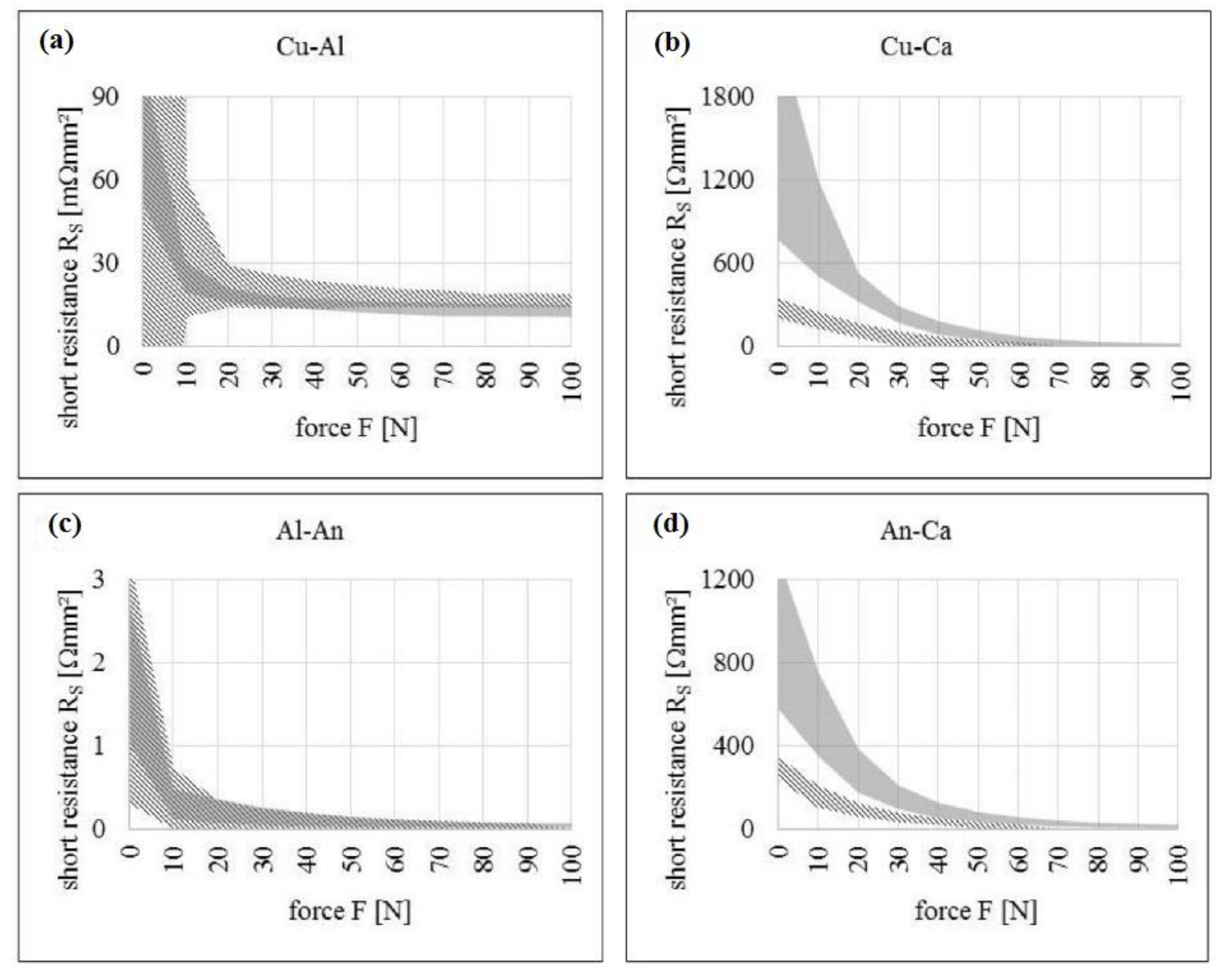
- Volck, T.; Sinz, W.; Gstrein, G.; Breitfuss, C.; Heindl, S.F.; Steffan, H.; Freunberger, S.; Wilkening, M.; Uitz, M.; Fink, C.; et al. Method for determination of the internal short resistance and heat evolution at different mechanical loads of a lithium ion battery cell based on dummy pouch cells. Batteries 2016, 2, 8. [Google Scholar] [CrossRef]
- Chen, Y.; Santhanagopalan, S.; Babu, V.; Ding, Y. Dynamic mechanical behavior of lithium-ion pouch cells subjected to high-velocity impact. Compos. Struct. 2019, 218, 50–59. [Google Scholar] [CrossRef]
- Orendorff, C.J.; Roth, E.P.; Nagasubramanian, G. Experimental triggers for internal short circuits in lithium-ion cells. J. Power Source 2011, 196, 6554–6558. [Google Scholar] [CrossRef]
- Beaumont, R.; Masters, I.; Das, A.; Lucas, S.; Thanikachalam, A.; Williams, D. Methodology for developing a macro finite element model of lithium-ion pouch cells for predicting mechanical behaviour under multiple loading conditions. Energies 2021, 14, 1921. [Google Scholar] [CrossRef]
- Sahraei, E.; Meier, J.; Wierzbicki, T. Characterizing and modeling mechanical properties and onset of short circuit for three types of lithium-ion pouch cells. J. Power Source 2014, 247, 503–516. [Google Scholar] [CrossRef]
- Santhanagopalan, S.; Ramadass, P.; Zhang, J. Analysis of internal short-circuit in a lithium ion cell. J. Power Source 2009, 194, 550–557. [Google Scholar] [CrossRef]
- Semenov, N.N. Some Problems in Chemical Kinetics and Reactivity; Pergamon Press Ltd.: London, UK, 1959; Volume 2, ISBN 9780691626277. [Google Scholar]
- Wang, Q.; Ping, P.; Zhao, X.; Chu, G.; Sun, J.; Chen, C. Thermal runaway caused fire and explosion of lithium ion battery. J. Power Source 2012, 208, 210–224. [Google Scholar] [CrossRef]
- Wang, Q.; Sun, J.; Chu, G. Lithium ion battery fire and explosion. Fire Saf. Sci. 2005, 8, 375–382. [Google Scholar] [CrossRef]
- Spotnitz, R.; Franklin, J. Abuse behavior of high-power, lithium-ion cells. J. Power Source 2003, 113, 81–100. [Google Scholar] [CrossRef]
- Richard, M.N.; Dahn, J.R. Accelerating rate calorimetry studies of the effect of binder type on the thermal stability of a lithiated mesocarbon microbead material in electrolyte. J. Power Source 1999, 83, 71–74. [Google Scholar] [CrossRef]
- Chen, Z.; Belharouak, I.; Sun, Y.K.; Amine, K. Titanium-based anode materials for safe lithium-ion batteries. Adv. Funct. Mater. 2013, 23, 959–969. [Google Scholar] [CrossRef]
- Wang, Q.; Sun, J.; Yao, X.; Chen, C. Thermal stability of LiPF6/EC + DEC electrolyte with charged electrodes for lithium ion batteries. Thermochim. Acta 2005, 437, 12–16. [Google Scholar] [CrossRef]
- Chen, Z.; Qin, Y.; Ren, Y.; Lu, W.; Orendorff, C.; Roth, E.P.; Amine, K. Multi-scale study of thermal stability of lithiated graphite. Energy Environ. Sci. 2011, 4, 4023–4030. [Google Scholar] [CrossRef]
- Martha, S.K.; Haik, O.; Zinigrad, E.; Exnar, I.; Drezen, T.; Miners, J.H.; Aurbach, D. On the Thermal Stability of Olivine Cathode Materials for Lithium-Ion Batteries. J. Electrochem. Soc. 2011, 158, A1115. [Google Scholar] [CrossRef]
- Wang, Q.; Sun, J.; Chen, X.; Chu, G.; Chen, C. Effects of solvents and salt on the thermal stability of charged LiCoO2. Mater. Res. Bull. 2009, 44, 543–548. [Google Scholar] [CrossRef]
- Shigematsu, Y.; Ue, M.; Yamaki, J. Thermal Behavior of Charged Graphite and LixCoO2 in Electrolytes Containing Alkyl Phosphate for Lithium-Ion Cells. J. Electrochem. Soc. 2009, 156, A176. [Google Scholar] [CrossRef]
- Lee, S.Y.; Kim, S.K.; Ahn, S. Performances and thermal stability of LiCoO2 cathodes encapsulated by a new gel polymer electrolyte. J. Power Source 2007, 174, 480–483. [Google Scholar] [CrossRef]
- Jiang, J.; Dahn, J.R. Effects of particle size and electrolyte salt on the thermal stability of Li0.5CoO2. Electrochim. Acta 2004, 49, 2661–2666. [Google Scholar] [CrossRef]
- Yamaki, J.I.; Baba, Y.; Katayama, N.; Takatsuji, H.; Egashira, M.; Okada, S. Thermal stability of electrolytes with LixCoO2 cathode or lithiated carbon anode. J. Power Source 2003, 119–121, 789–793. [Google Scholar] [CrossRef]
- Julien, C.M.; Mauger, A.; Karim, Z.; Groult, H. Comparative Issues of Cathode Materials for Li-Ion Batteries. Inorganics 2014, 2, 132–154. [Google Scholar] [CrossRef] [Green Version]
- Wang, Y.; Jiang, J.; Dahn, J.R. The reactivity of delithiated Li(Ni1/3Co1/3Mn1/3)O2, Li(Ni0.8Co0.15Al0.05)O2 or LiCoO2 with non-aqueous electrolyte. Electrochem. Commun. 2007, 9, 2534–2540. [Google Scholar] [CrossRef]
- Jo, M.; Noh, M.; Oh, P.; Kim, Y.; Cho, J. A new high power LiNi0.81Co0.1Al0.09O2 cathode material for lithium-ion batteries. Adv. Energy Mater. 2014, 4, 1301583. [Google Scholar] [CrossRef]
- Huang, Y.; Lin, Y.C.; Jenkins, D.M.; Chernova, N.A.; Chung, Y.; Radhakrishnan, B.; Chu, I.H.; Fang, J.; Wang, Q.; Omenya, F.; et al. Thermal Stability and Reactivity of Cathode Materials for Li-Ion Batteries. ACS Appl. Mater. Interfaces 2016, 8, 7013–7021. [Google Scholar] [CrossRef] [Green Version]
- Wang, H.; Tang, A.; Huang, K. Oxygen evolution in overcharged LixNi1/3Co1/3Mn1/3O2 electrode and its thermal analysis kinetics. Chin. J. Chem. 2011, 29, 1583–1588. [Google Scholar] [CrossRef]
- Kim, H.S.; Kong, M.; Kim, K.; Kim, I.J.; Gu, H.B. Effect of carbon coating on LiNi1/3Mn1/3Co1/3O2 cathode material for lithium secondary batteries. J. Power Source 2007, 171, 917–921. [Google Scholar] [CrossRef]
- Kim, H.S.; Kim, K.; Moon, S.I.; Kim, I.J.; Gu, H.B. A study on carbon-coated LiNi1/3Mn1/3Co1/3O2 cathode material for lithium secondary batteries. J. Solid State Electrochem. 2008, 12, 867–872. [Google Scholar] [CrossRef]
- Belharouak, I.; Sun, Y.K.; Liu, J.; Amine, K. Li(Ni1/3Co1/3Mn1/3)O2 as a suitable cathode for high power applications. J. Power Source 2003, 123, 247–252. [Google Scholar] [CrossRef]
- Zhang, Z.; Fouchard, D.; Rea, J.R. Differential scanning calorimetry material studies: Implications for the safety of lithium-ion cells. J. Power Source 1998, 70, 16–20. [Google Scholar] [CrossRef]
- Feng, X.; Fang, M.; He, X.; Ouyang, M.; Lu, L.; Wang, H.; Zhang, M. Thermal runaway features of large format prismatic lithium ion battery using extended volume accelerating rate calorimetry. J. Power Source 2014, 255, 294–301. [Google Scholar] [CrossRef]
- Röder, P.; Baba, N.; Friedrich, K.A.; Wiemhöfer, H.D. Impact of delithiated Li0FePO4 on the decomposition of LiPF6-based electrolyte studied by accelerating rate calorimetry. J. Power Source 2013, 236, 151–157. [Google Scholar] [CrossRef]
- Jiang, J.; Dahn, J.R. ARC studies of the thermal stability of three different cathode materials: LiCoO2; Li[Ni0.1Co0.8Mn0.1]O2; and LiFePO4, in LiPF6 and LiBoB EC/DEC electrolytes. Electrochem. Commun. 2004, 6, 39–43. [Google Scholar] [CrossRef]
- Feng, X.; Ouyang, M.; Liu, X.; Lu, L.; Xia, Y.; He, X. Thermal runaway mechanism of lithium ion battery for electric vehicles: A review. Energy Storage Mater. 2018, 10, 246–267. [Google Scholar] [CrossRef]
- Biensan, P.; Simon, B.; Pérès, J.P.; De Guibert, A.; Broussely, M.; Bodet, J.M.; Perton, F. On safety of lithium-ion cells. J. Power Source 1999, 81–82, 906–912. [Google Scholar] [CrossRef]
- Wang, Q.; Sun, J.; Chen, C. Thermal Stability of Delithiated LiMn2O4 with Electrolyte for Lithium-Ion Batteries. J. Electrochem. Soc. 2007, 154, A263. [Google Scholar] [CrossRef]
- Fei, S.T.; Allcock, H.R. Methoxyethoxyethoxyphosphazenes as ionic conductive fire retardant additives for lithium battery systems. J. Power Source 2010, 195, 2082–2088. [Google Scholar] [CrossRef]
- Balakrishnan, P.G.; Ramesh, R.; Prem Kumar, T. Safety mechanisms in lithium-ion batteries. J. Power Source 2006, 155, 401–414. [Google Scholar] [CrossRef]
- Lisbona, D.; Snee, T. A review of hazards associated with primary lithium and lithium-ion batteries. Process Saf. Environ. Prot. 2011, 89, 434–442. [Google Scholar] [CrossRef]
- Chen, D.; Jiang, J.; Kim, G.H.; Yang, C.; Pesaran, A. Comparison of different cooling methods for lithium ion battery cells. Appl. Therm. Eng. 2016, 94, 846–854. [Google Scholar] [CrossRef] [Green Version]
- Jung, Y.S.; Cavanagh, A.S.; Riley, L.A.; Kang, S.H.; Dillon, A.C.; Groner, M.D.; George, S.M.; Lee, S.H. Ultrathin direct atomic layer deposition on composite electrodes for highly durable and safe Li-Ion batteries. Adv. Mater. 2010, 22, 2172–2176. [Google Scholar] [CrossRef]
- Baginska, M.; Blaiszik, B.J.; Merriman, R.J.; Sottos, N.R.; Moore, J.S.; White, S.R. Autonomic shutdown of Lithium-ion batteries using thermoresponsive microspheres. Adv. Energy Mater. 2012, 2, 583–590. [Google Scholar] [CrossRef]
- Yao, X.L.; Xie, S.; Chen, C.H.; Wang, Q.S.; Sun, J.H.; Li, Y.L.; Lu, S.X. Comparisons of graphite and spinel Li1.33Ti1.67O4 as anode materials for rechargeable lithium-ion batteries. Electrochim. Acta 2005, 50, 4076–4081. [Google Scholar] [CrossRef]
- Chan, C.K.; Peng, H.; Liu, G.; McIlwrath, K.; Zhang, X.F.; Huggins, R.A.; Cui, Y. High-performance lithium battery anodes using silicon nanowires. Nat. Nanotechnol. 2008, 3, 31–35. [Google Scholar] [CrossRef] [PubMed]
- Zhang, S.S. A review on electrolyte additives for lithium-ion batteries. J. Power Source 2006, 162, 1379–1394. [Google Scholar] [CrossRef]
- Li, C.; Zhang, H.P.; Fu, L.J.; Liu, H.; Wu, Y.P.; Rahm, E.; Holze, R.; Wu, H.Q. Cathode materials modified by surface coating for lithium ion batteries. Electrochim. Acta 2006, 51, 3872–3883. [Google Scholar] [CrossRef]
- Li, G.; Yang, Z.; Yang, W. Effect of FePO4 coating on electrochemical and safety performance of LiCoCO2 as cathode material for Li-ion batteries. J. Power Source 2008, 183, 741–748. [Google Scholar] [CrossRef]
- Li, J.; Fan, M.; He, X.; Zhao, R.; Jiange, C.; Wan, C. TiO2 coating of LiNi1/3Co1/3Mn1/3O2 cathode materials for Li-ion batteries. Ionics 2006, 12, 215–218. [Google Scholar] [CrossRef]
- Sun, Y.-K.; Cho, S.-W.; Lee, S.-W.; Yoon, C.S.; Amine, K. AlF3-Coating to Improve High Voltage Cycling Performance of Li[Ni1/3Co1/3Mn1/3]O2 Cathode Materials for Lithium Secondary Batteries. J. Electrochem. Soc. 2007, 154, A168. [Google Scholar] [CrossRef]
- Zhou, F.; Zhao, X.; Goodbrake, C.; Jiang, J.; Dahn, J.R. Solid-State Synthesis as a Method for the Substitution of Al for Co in LiNi1/3Mn1/3Co(1/3−z)AlzO2. J. Electrochem. Soc. 2009, 156, A796. [Google Scholar] [CrossRef]
- Shim, E.G.; Nam, T.H.; Kim, J.G.; Kim, H.S.; Moon, S.I. Electrochemical performance of lithium-ion batteries with triphenylphosphate as a flame-retardant additive. J. Power Source 2007, 172, 919–924. [Google Scholar] [CrossRef]
- Dagger, T.; Rad, B.R.; Schappacher, F.M.; Winter, M. Comparative Performance Evaluation of Flame Retardant Additives for Lithium Ion Batteries—I. Safety, Chemical and Electrochemical Stabilities. Energy Technol. 2018, 6, 2011–2022. [Google Scholar] [CrossRef]
- Wang, X.; Yasukawa, E.; Kasuya, S. Nonflammable Trimethyl Phosphate Solvent-Containing Electrolytes for Lithium-Ion Batteries: I. Fundamental Properties. J. Electrochem. Soc. 2001, 148, A1058. [Google Scholar] [CrossRef]
- Kalhoff, J.; Eshetu, G.G.; Bresser, D.; Passerini, S. Safer Electrolytes for Lithium-Ion Batteries: State of the Art and Perspectives. ChemSusChem 2015, 8, 2154–2175. [Google Scholar] [CrossRef]
- Xu, K.; Ding, M.S.; Zhang, S.; Allen, J.L.; Jow, T.R. An Attempt to Formulate Nonflammable Lithium Ion Electrolytes with Alkyl Phosphates and Phosphazenes. J. Electrochem. Soc. 2002, 149, A622. [Google Scholar] [CrossRef]
- Zeng, Z.; Wu, B.; Xiao, L.; Jiang, X.; Chen, Y.; Ai, X.; Yang, H.; Cao, Y. Safer lithium ion batteries based on nonflammable electrolyte. J. Power Source 2015, 279, 6–12. [Google Scholar] [CrossRef]
- Lee, H.H.; Wang, Y.Y.; Wan, C.C.; Yang, M.H.; Wu, H.C.; Shieh, D.T. The function of vinylene carbonate as a thermal additive to electrolyte in lithium batteries. J. Appl. Electrochem. 2005, 35, 615–623. [Google Scholar] [CrossRef]
- Zhang, S.S. A review on the separators of liquid electrolyte Li-ion batteries. J. Power Source 2007, 164, 351–364. [Google Scholar] [CrossRef]
- Zhu, Y.; Wang, F.; Liu, L.; Xiao, S.; Chang, Z.; Wu, Y. Composite of a nonwoven fabric with poly(vinylidene fluoride) as a gel membrane of high safety for lithium ion battery. Energy Environ. Sci. 2013, 6, 618–624. [Google Scholar] [CrossRef]
- Choi, J.A.; Kim, S.H.; Kim, D.W. Enhancement of thermal stability and cycling performance in lithium-ion cells through the use of ceramic-coated separators. J. Power Source 2010, 195, 6192–6196. [Google Scholar] [CrossRef]
- Shi, C.; Zhang, P.; Chen, L.; Yang, P.; Zhao, J. Effect of a thin ceramic-coating layer on thermal and electrochemical properties of polyethylene separator for lithium-ion batteries. J. Power Source 2014, 270, 547–553. [Google Scholar] [CrossRef]
- Lee, H.; Ren, X.; Niu, C.; Yu, L.; Engelhard, M.H.; Cho, I.; Ryou, M.H.; Jin, H.S.; Kim, H.T.; Liu, J.; et al. Suppressing Lithium Dendrite Growth by Metallic Coating on a Separator. Adv. Funct. Mater. 2017, 27, 1704391. [Google Scholar] [CrossRef]
- Hannan, M.A.; Lipu, M.S.H.; Hussain, A.; Mohamed, A. A review of lithium-ion battery state of charge estimation and management system in electric vehicle applications: Challenges and recommendations. Renew. Sustain. Energy Rev. 2017, 78, 834–854. [Google Scholar] [CrossRef]
- Javed, K.; Gouriveau, R.; Zerhouni, N. State of the art and taxonomy of prognostics approaches, trends of prognostics applications and open issues towards maturity at different technology readiness levels. Mech. Syst. Signal Process. 2017, 94, 214–236. [Google Scholar] [CrossRef]
- Rahimi-Eichi, H.; Ojha, U.; Baronti, F.; Chow, M.Y. Battery management system: An overview of its application in the smart grid and electric vehicles. IEEE Ind. Electron. Mag. 2013, 7, 4–16. [Google Scholar] [CrossRef]
- Omariba, Z.B.; Zhang, L.; Sun, D. Review on health management system for lithium-ion batteries of electric vehicles. Electronics 2018, 7, 72. [Google Scholar] [CrossRef] [Green Version]
- Yamamoto, Y.; Kato, H.; Nishi, Y. Overcharge Protection of Lithium Ion Rechargeable Batteries. In Proceedings of the 184th Electrochemical Society Fall Meeting, New Orleans, LA, USA, 10–15 October 1993; ECS: New Orleans, LA, USA, 1993; Volume 2. [Google Scholar]
- Kong, L.; Li, C.; Jiang, J.; Pecht, M.G. Li-ion battery fire hazards and safety strategies. Energies 2018, 11, 2191. [Google Scholar] [CrossRef] [Green Version]
- Yao, X.Y.; Kong, L.; Pecht, M.G. Reliability of Cylindrical Li-ion Battery Safety Vents. IEEE Access 2020, 8, 101859–101866. [Google Scholar] [CrossRef]
- Kise, M.; Yoshioka, S.; Kuriki, H. Relation between composition of the positive electrode and cell performance and safety of lithium-ion PTC batteries. J. Power Source 2007, 174, 861–866. [Google Scholar] [CrossRef]
- Ilic, D.; Birke, P.; Holl, K.; Wöhrle, T.; Haug, P.; Birke-Salam, F. PoLiFlexTM, the innovative lithium-polymer battery. J. Power Source 2004, 129, 34–37. [Google Scholar] [CrossRef]
- Wang, Y.W.; Jiang, J.M.; Chung, Y.H.; Chen, W.C.; Shu, C.M. Forced-air cooling system for large-scale lithium-ion battery modules during charge and discharge processes. J. Therm. Anal. Calorim. 2019, 135, 2891–2901. [Google Scholar] [CrossRef]
- Teng, H.; Ma, Y.; Yeow, K.; Thelliez, M. An Analysis of a Lithium-ion Battery System with Indirect Air Cooling and Warm-Up. SAE Int. J. Passeng. Cars Mech. Syst. 2011, 4, 1343–1357. [Google Scholar] [CrossRef]
- Deng, Y.; Feng, C.; Jiaqiang, E.; Zhu, H.; Chen, J.; Wen, M.; Yin, H. Effects of different coolants and cooling strategies on the cooling performance of the power lithium ion battery system: A review. Appl. Therm. Eng. 2018, 142, 10–29. [Google Scholar] [CrossRef]
- Mohammadian, S.K.; He, Y.L.; Zhang, Y. Internal cooling of a lithium-ion battery using electrolyte as coolant through microchannels embedded inside the electrodes. J. Power Source 2015, 293, 458–466. [Google Scholar] [CrossRef]
- De Vita, A.; Maheshwari, A.; Destro, M.; Santarelli, M.; Carello, M. Transient thermal analysis of a lithium-ion battery pack comparing different cooling solutions for automotive applications. Appl. Energy 2017, 206, 101–112. [Google Scholar] [CrossRef]
- Wang, Q.; Jiang, B.; Li, B.; Yan, Y. A critical review of thermal management models and solutions of lithium-ion batteries for the development of pure electric vehicles. Renew. Sustain. Energy Rev. 2016, 64, 106–128. [Google Scholar] [CrossRef]
- Rao, Z.; Wang, S.; Zhang, G. Simulation and experiment of thermal energy management with phase change material for ageing LiFePO4 power battery. Energy Convers. Manag. 2011, 52, 3408–3414. [Google Scholar] [CrossRef]
- Zhu, J.; Zhang, X.; Wierzbicki, T.; Xia, Y.; Chen, G. Structural Designs for Electric Vehicle Battery Pack against Ground Impact; SAE Technical Paper 2018-01-1438; SAE International: Warrendale, PA, USA, 2018; Volume 2018. [Google Scholar]
- Irawan, D.; Santosa, S.P.; Jusuf, A.; Sambegoro, P.L. Sandwich Panel Composite Based Light-Weight Structure Design for Reserved Energy Storage System (RESS) Protection. In Proceedings of the 2019 6th International Conference on Electric Vehicular Technology (ICEVT), Bali, Indonesia, 18–21 November 2019; pp. 124–134. [Google Scholar]
- Halimah, P.N.; Santosa, S.P.; Jusuf, A.; Dirgantara, T. The Concept of Sandwich Panel Structures for Battery Protections in Electric Vehicles Subjected to Ground Impact. In Proceedings of the 2018 5th International Conference on Electric Vehicular Technology (ICEVT), Surakarta, Indonesia, 30–31 October 2018; pp. 142–146. [Google Scholar]
- Hou, S.; Zhao, S.; Ren, L.; Han, X.; Li, Q. Crashworthiness optimization of corrugated sandwich panels. Mater. Des. 2013, 51, 1071–1084. [Google Scholar] [CrossRef]
- Larsson, F.; Andersson, P.; Blomqvist, P.; Mellander, B.E. Toxic fluoride gas emissions from lithium-ion battery fires. Sci. Rep. 2017, 7, 10018. [Google Scholar] [CrossRef]
- Andersson, P.; Arvidson, M.; Evegren, F.; Jandali, M.; Larsson, F.; Rosengren, M. Safety and Transport Safety Lion Fire: Extinguishment and Mitigation of Fires in Li-Ion Batteries at Sea; RISE Research Institutes of Sweden AB: Boras, Sweden, 2018; ISBN 9789188907271. [Google Scholar]
- Liu, Y.; Duan, Q.; Xu, J.; Li, H.; Sun, J.; Wang, Q. Experimental study on a novel safety strategy of lithium-ion battery integrating fire suppression and rapid cooling. J. Energy Storage 2020, 28, 101185. [Google Scholar] [CrossRef]
- Summer, S.M. Flammability Assessment of Lithium-Ion and Lithium-Ion Polymer Battery Cells Designed for Aircraft Power Usage; U.S. Department of Transportation: Washington, DC, USA, 2010.
- Wang, Q.; Shao, G.; Duan, Q.; Chen, M.; Li, Y.; Wu, K.; Liu, B.; Peng, P.; Sun, J. The Efficiency of Heptafluoropropane Fire Extinguishing Agent on Suppressing the Lithium Titanate Battery Fire. Fire Technol. 2016, 52, 387–396. [Google Scholar] [CrossRef]


| Contact Mode | Resistance to ISCs | Temperature Rise | Heat Generation | Heat Conductivity | Severity of Failure | Probability of Occurrence |
|---|---|---|---|---|---|---|
| Anode-Current collector (Cu-Foil) | Low | Low | High | High | Most dangerous | No data available |
| Cathode-Anode | High | High | Comparatively low | Low | Second most dangerous | Maximum |
| Current collector- Cathode (Al–foil) | High | Low | Least | High | Low | Minimum to rare |
| Current collector- Current Collector | Low | Low | Highest | Highest | No data available | Low |
Publisher’s Note: MDPI stays neutral with regard to jurisdictional claims in published maps and institutional affiliations. |
© 2021 by the authors. Licensee MDPI, Basel, Switzerland. This article is an open access article distributed under the terms and conditions of the Creative Commons Attribution (CC BY) license (https://creativecommons.org/licenses/by/4.0/).
Share and Cite
Kaliaperumal, M.; Dharanendrakumar, M.S.; Prasanna, S.; Abhishek, K.V.; Chidambaram, R.K.; Adams, S.; Zaghib, K.; Reddy, M.V. Cause and Mitigation of Lithium-Ion Battery Failure—A Review. Materials 2021, 14, 5676. https://doi.org/10.3390/ma14195676
Kaliaperumal M, Dharanendrakumar MS, Prasanna S, Abhishek KV, Chidambaram RK, Adams S, Zaghib K, Reddy MV. Cause and Mitigation of Lithium-Ion Battery Failure—A Review. Materials. 2021; 14(19):5676. https://doi.org/10.3390/ma14195676
Chicago/Turabian StyleKaliaperumal, Muthukrishnan, Milindar S. Dharanendrakumar, Santosh Prasanna, Kaginele V. Abhishek, Ramesh Kumar Chidambaram, Stefan Adams, Karim Zaghib, and M. V. Reddy. 2021. "Cause and Mitigation of Lithium-Ion Battery Failure—A Review" Materials 14, no. 19: 5676. https://doi.org/10.3390/ma14195676