
Hybrid Welding (Laser–Electric Arc MAG) of High Yield Point Steel S960QL


Abstract
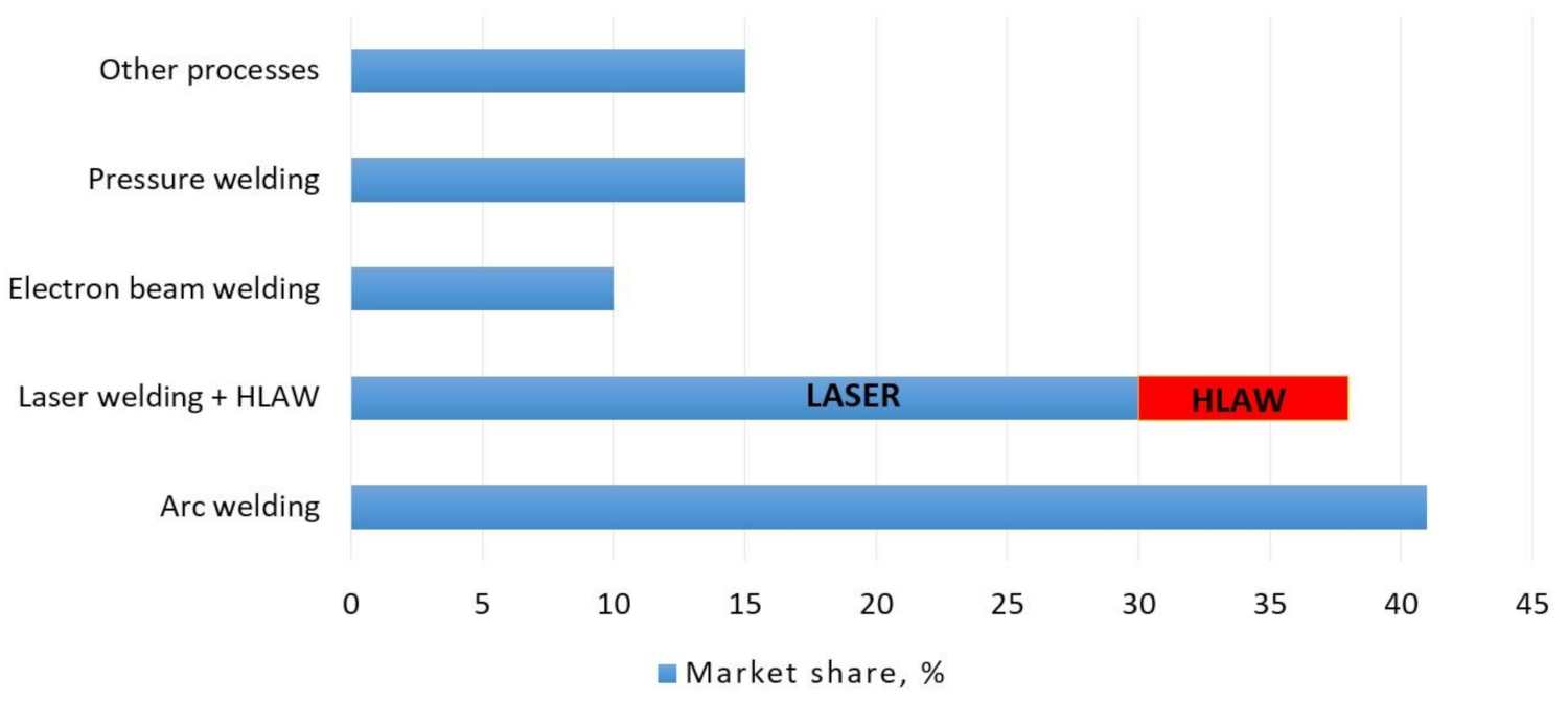
:1. Introduction
2. Materials and Methods
2.1. Materials
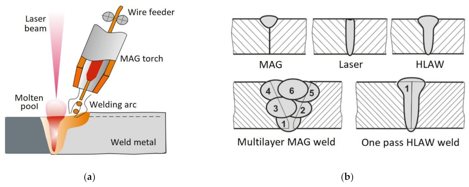
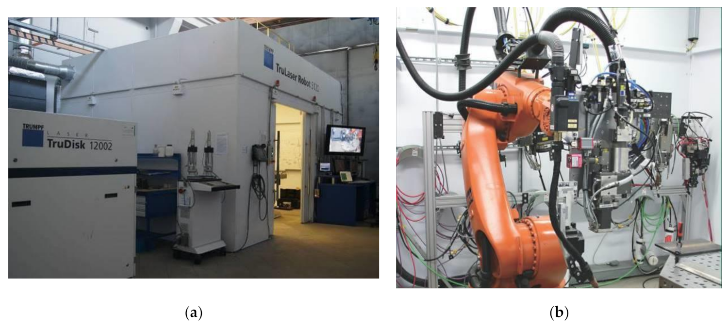
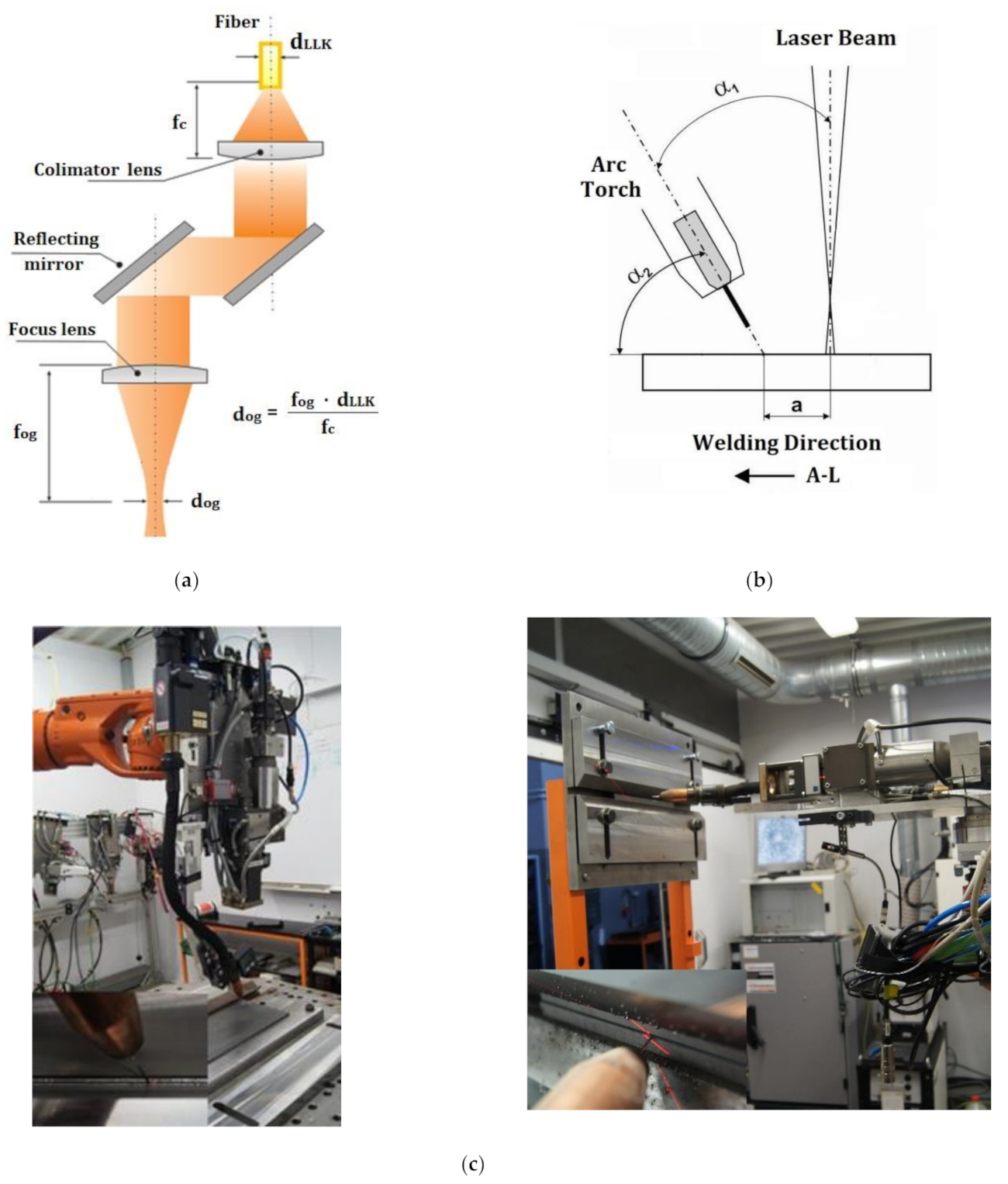
2.2. Welding Method and Equipment
2.3. Tests of Welded Joints
- Visual tests performed in accordance with the requirements of the ISO 17637 standard;
- Radiographic tests of the welded joints, performed in accordance with the requirements of the ISO 17636-1 standard and involving the use of an Eresco 65 MF3 X-ray unit (GE Sensing&Inspection Technologies; Ahrensburg, Germany);
- Macroscopic metallographic tests, performed using an Olympus SZX9 stereoscopic microscope (Olympus, Tokyo, Japan). To identify their structure, the specimens were subjected to etching in Adler’s reagent (Chmes, Poznań, Poland);
- Microscopic metallographic tests, performed in accordance with the requirements of the ISO 17639 standard and involving the use of a Nikon Eclipse MA200 light microscope (Leuven, Belgium). The specimens were subjected to grinding with abrasive paper having a granularity of 800 and 1000, polishing performed using a powerpro 4000 grinder/polisher (Buehler; Germany) and metaldi Monocrystalline Diamond Suspension (3 µm), as well as etching in 5% Nital (5% HNO3 in ethanol);
- Tests performed using a scanning transmission electron microscope (STEM) involving the use of thin foils; the specimens were subjected to two-sided grinding (with abrasive paper) to reach a thickness of 0.5 mm. The process of electrochemical thinning was performed using a Struers tenupol-5 machine, with a voltage of 45 V and a temperature of 5 °C. The process was carried out in electrolyte composed of 70% CH20H, 20% glycerine, and 10% hclo4. The cooling agent was liquid nitrogen. The tests were performed using a Hitachi 2300A scanning-transmission electron microscope (STEM) (Japan), illuminating thin foils. The microscope was equipped with an FEG-type gun provided with the Schottky emitter. The accelerating voltage during the tests amounted to 200 kv;
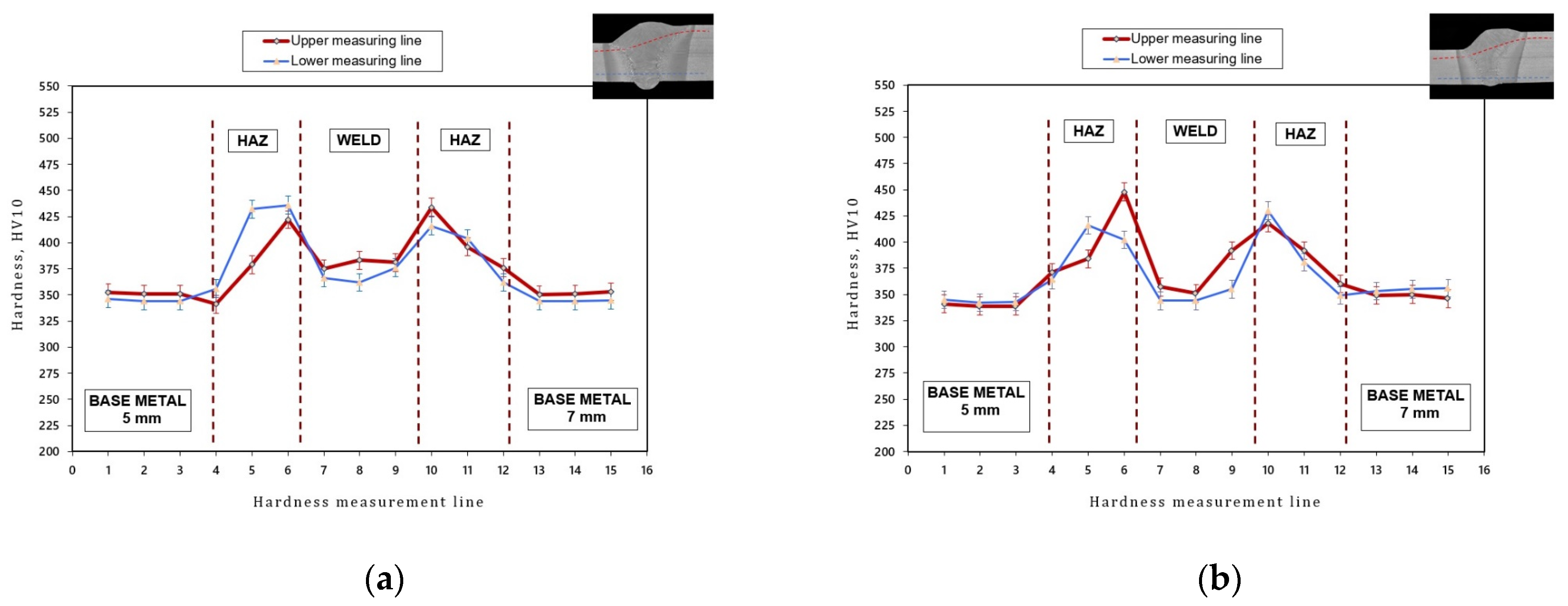
- Hardness distribution tests were performed in accordance with the requirements of the ISO 9015-1 standard and involved the use of a GNEHM DIGITAL BRICKERS 220 hardness tester. Vickers hardness tests (HV) were performed along two measurement lines located 2 mm away from the upper and lower edge of the specimen. The imprints were made in the base material, heat-affected zone (HAZ) and in the weld;
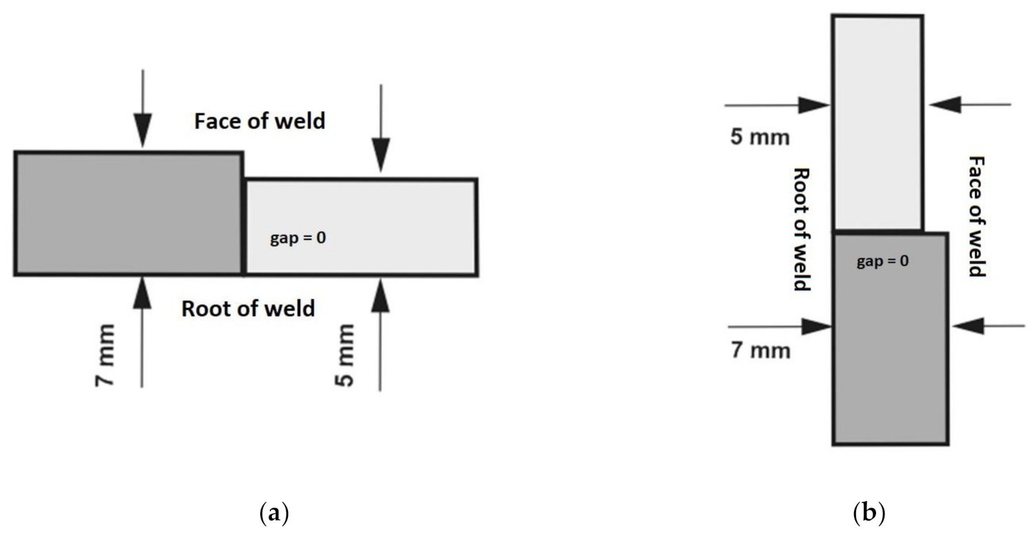
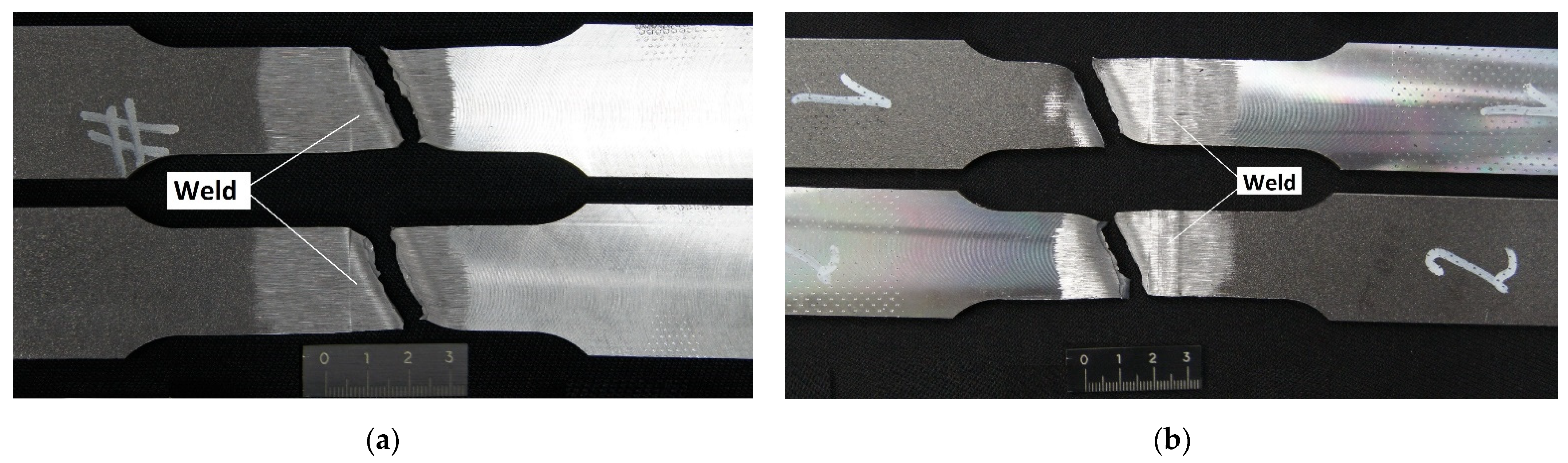
- Static tensile tests involved 2 specimens cut out perpendicularly to the weld and prepared in accordance with the requirements of the ISO 6892-1 standard. The preparation of the specimens involved the removal of excessive root and face reinforcement as well as the mechanical reduction of specimen thickness from 7 mm to 5 mm (performed to obtain the even surface of the plates across the entire specimen). The dimensions of the specimens were 300 mm × 25 mm × 5.0 mm. The tension rate amounted to 10 mm/min. The tests were performed using an MTS 810 TEST SYSTEMS testing machine (Eden Prairie, MN, USA);
- Face bend test (FBB) and root bend test (RBB) of the butt weld were performed in accordance with the requirements of the ISO 5173 standard. The tests involved 4 specimens—two specimens on each side. The thickness of the plate was mechanically reduced from 7 mm to 5 mm (in order to obtain the even surface of the plates across the entire specimen). The dimensions of the specimens were 300 mm × 20 mm × 5.0 mm). The tests were performed using a LOS12126 testing machine (Losenhausenwerk AG; Düsseldorf, Germany);
- Impact strength tests, performed in accordance with the requirements of the ISO 9016 standard, involved the use of 2 sets of specimens (3 specimens in each set) sampled from the weld area and from the heat-affected zone (HAZ). The cross-section of the specimens used in the test was reduced. The dimensions of the specimens were 2.5 mm × 8.0 mm × 55 mm. The depth of the V notch amounted to 2 mm. Before the tests, the specimens were cooled to a temperature of −40 °C. The cooling process was performed using an FP89 cooling circulator (Julabo). Impact energy was identified using an RKP 300 impact-testing machine (Amsler).
3. Results and Discussion
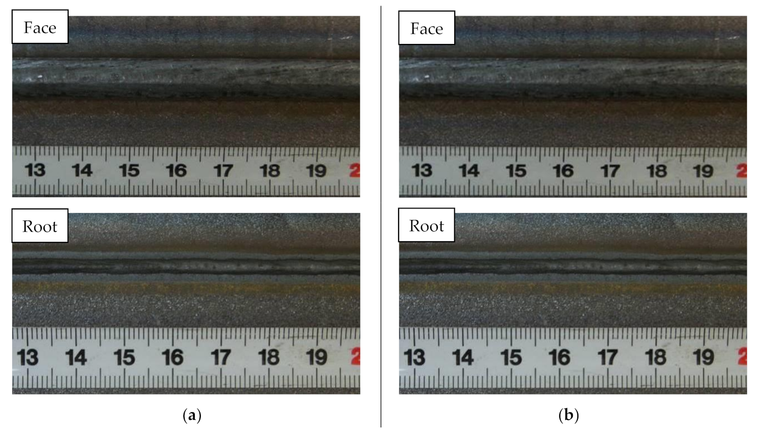
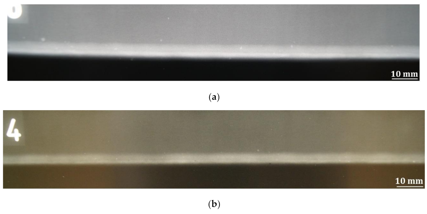
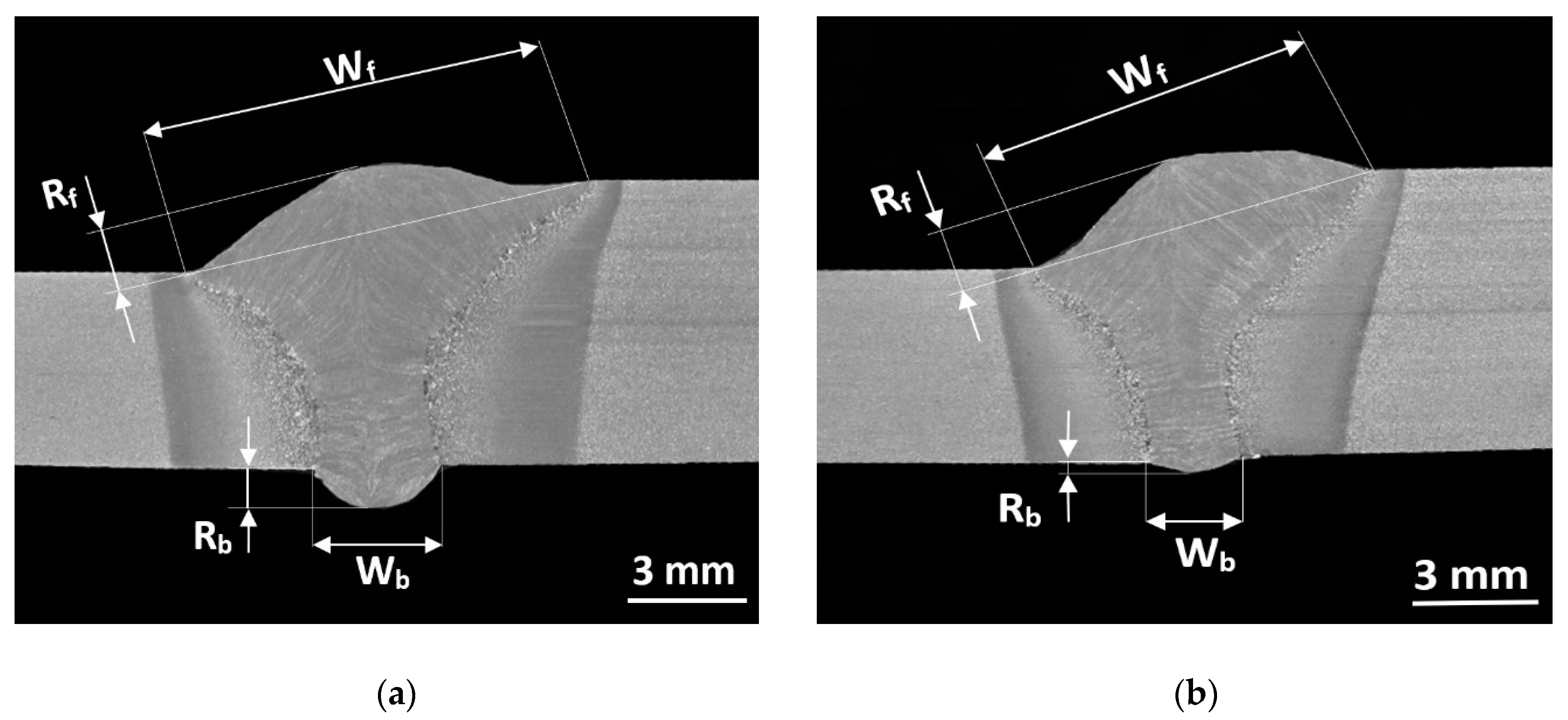
3.1. Weld Formation
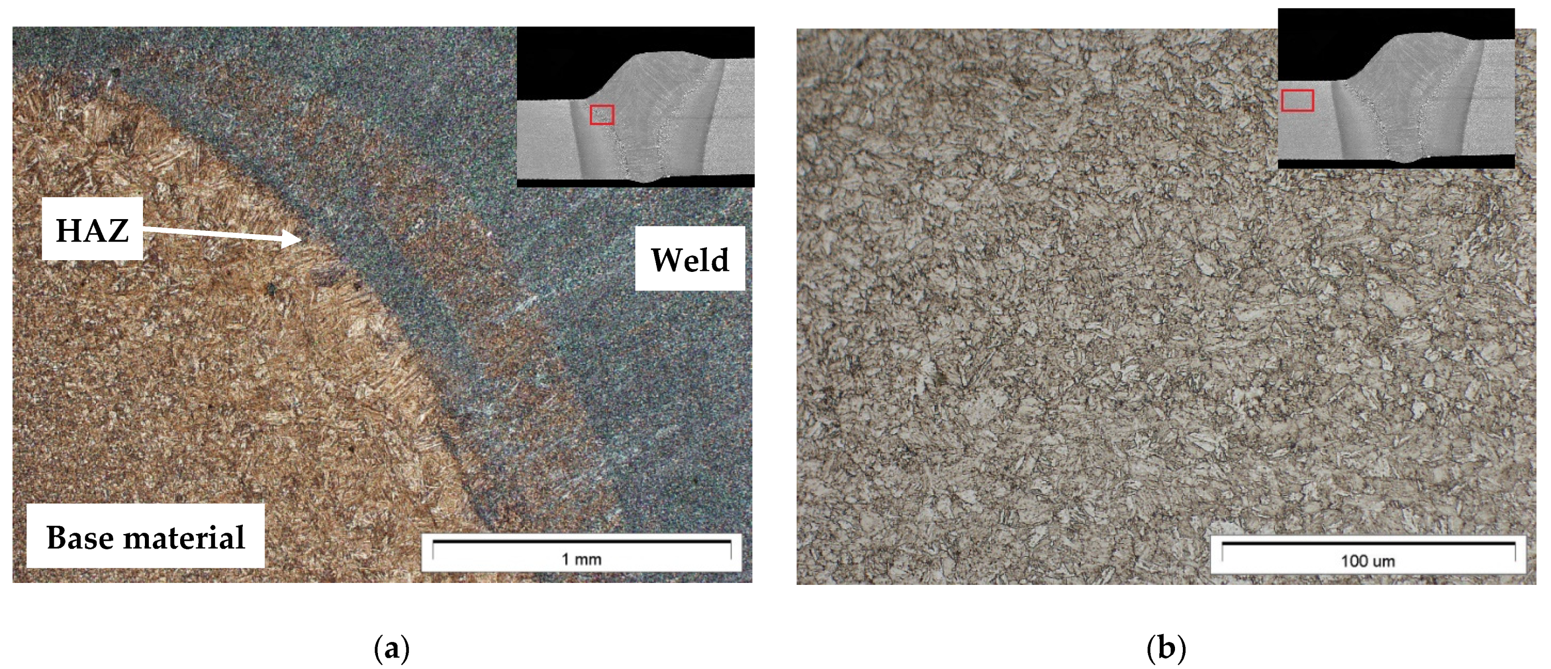
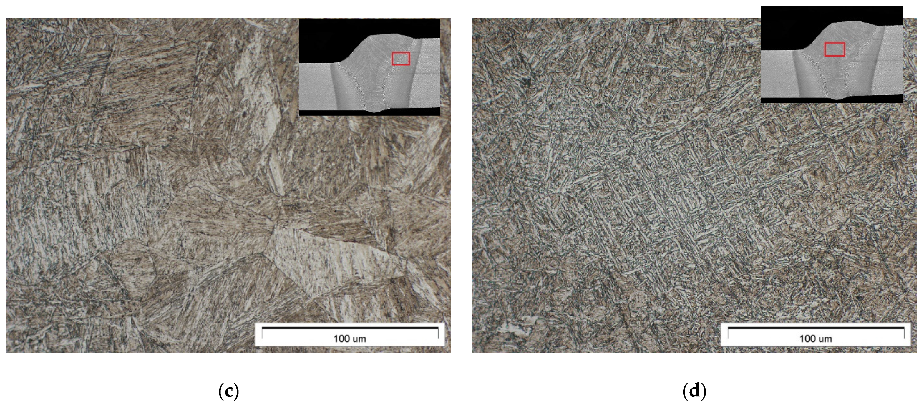
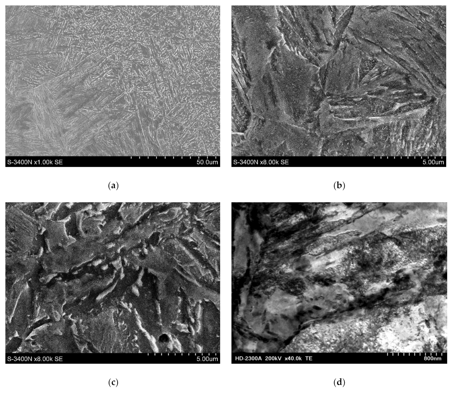
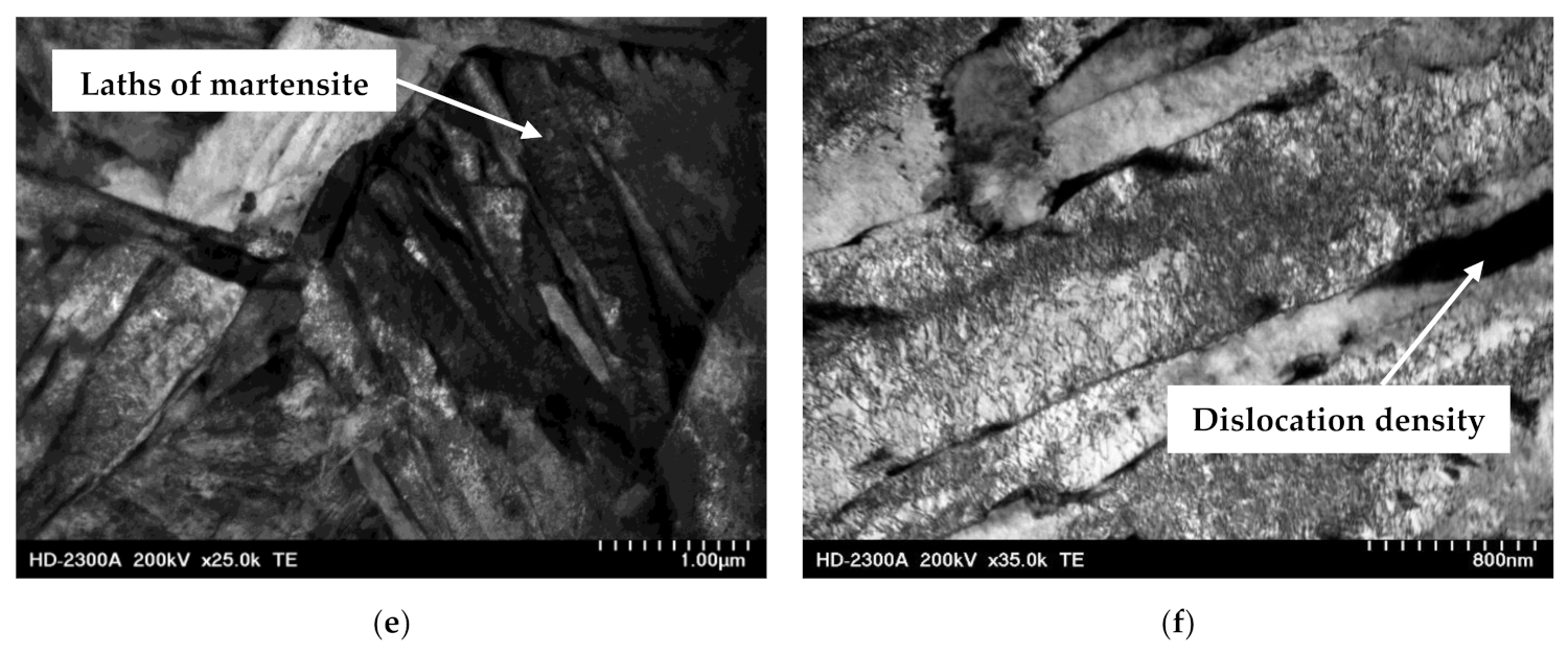
3.2. Microstructure Characteristics
3.3. Hardness Distribution
3.4. Mechanical Properties
4. Conclusions
Author Contributions
Funding
Conflicts of Interest
References
- Acherjee, B. Hybrid laser arc welding: State-of-art review. Opt. Laser Technol. 2018, 99, 60–71. [Google Scholar] [CrossRef]
- Kawahito, Y.; Wang, H.; Katayama, S.; Sumimori, D. Ultra high power (100 kW) fiber laser welding of steel. Opt. Lett. 2018, 43, 4667–4670. [Google Scholar] [CrossRef]
- Nielsen, S.E. “High power laser hybrid welding—challenges and perspectives”, 15th Nordic Laser Materials Processing Conference, Nolamp 15, 25–27 August 2015, Lappeenranta, Finland. Phys. Procedia 2015, 78, 24–34. [Google Scholar] [CrossRef]
- Brian, M. Victor “Hybrid laser arc welding”, Edison Welding Institute, ASM Handbook. Weld. Fundam. Process. 2011, 6A. [Google Scholar]
- Shenghai, Z.; Yifu, S.; Huijuan, Q. The technology and welding joint properties of hybrid laser-TIG welding on thick plate. Opt. Laser Technol. 2013, 48, 381–388. [Google Scholar] [CrossRef]
- Innovationen Für die Wirtschaft. Forschung in der Fügetechnik DVS. 2015. Available online: https://www.dvs-ev.de/fv/neu/GB2017.pdf (accessed on 30 April 2016).
- Banasik, M.; Urbańczyk, M. Laser + MAG Hybrid Welding of Various Joints. Biul. Inst. Spaw. 2017, 1, 6–13. [Google Scholar]
- Steen, W.M.; Eboo, M. Arc-augmented laser welding. Met Constr. 1979, 11, 332–335. [Google Scholar]
- Steen, W.M. Arc-augmented laser processing of materials. J. Appl. Phys. 1980, 51, 5636–5641. [Google Scholar] [CrossRef]
- Silva, R.; Mano, M.D.C.; Rodrigues, B.M.; Sousa, S.M.J.; Pereira, M.; Ramos, B.B.; Schwedersky, B.M.; Silva, G.H.R. A comparison between LBW and hybrid laser-GMAW processes based on microstructure and weld geometry for hardenable steels. Int. J. Adv. Manuf. Technol. 2020, 110, 2801–2814. [Google Scholar] [CrossRef]
- Kah, P.; Salminen, A.; Martikainen, J. The influence of parameters on penetration, speed and bridging in laser hybrid welding. Mechanika 2011, 17, 324–333. [Google Scholar] [CrossRef]
- Adamiec, J.; Więcek, M.; Gawrysiuk, W. Fibre laser usage in boiler elements’ production for the power industry. Weld. Int. 2010, 24, 853–860. [Google Scholar] [CrossRef]
- Górka, J.; Stano, S. Microstructure and properties of hybrid laser arc welded joints (laser beam-MAG) in thermo-mechanical control processed S700MC steel. Metals 2018, 8, 132. [Google Scholar] [CrossRef] [Green Version]
- Li, C.; Muneharua, K.; Takao, S.; Kouji, H. Fiber laser-GMA hybrid welding of commercially pure titanium. Mater Des. 2009, 30, 109–114. [Google Scholar] [CrossRef]
- Shi, J.; Zhou, Y.; Liu, L. Application of pulsed laser-TIG hybrid heat source in root welding of thick plates titanium alloys. Appl Sci. 2017, 7, 527. [Google Scholar] [CrossRef] [Green Version]
- Casalino, G.; Campanelli, S.L.; DalMaso, U.; Ludovico, A.D. Arc leading versus laser leading in the hybrid welding of aluminium alloy using a fiber laser. Procedia CIRP 2013, 12, 151–156. [Google Scholar] [CrossRef]
- Huang, L.; Wu, D.; Hua, X.; Liu, S.; Jiang, Z.; Li, F.; Wang, H.; Shi, S. Effect of the welding direction on the microstructure characterization in fiber laser-GMAW hybrid welding of 5083 aluminium alloy. J Manuf. Process. 2018, 31, 514–522. [Google Scholar] [CrossRef]
- Han, X.; Yang, Z.; Ma, Y.; Shi, C.; Xin, Z. Comparative Study of Laser-Arc HybridWelding for AA6082-T6 Aluminum Alloy with Two Different Arc Modes. Metals 2020, 10, 407. [Google Scholar] [CrossRef] [Green Version]
- Thomy, C.; Vollertsen, F. Laser-MIG hybrid welding of aluminium to steel—Effect of process parameters on joint properties. Weld. World 2012, 56, 124–132. [Google Scholar] [CrossRef]
- Casalino, G.; Mortello, M.; Perulli, P.; Varone, A. Effects of laser offset and hybrid laser on microstructure and IMC in Fe-Al dissimilar welding. Metals 2017, 7, 282. [Google Scholar] [CrossRef] [Green Version]
- Turichin, G.; Klimova-Korsmik, O.; Skylar, M.; Zhitenev, A.; Kurakin, A.; Pozdnyakov, A. Laser-arc hybrid welding perspective ultra-high strength steels: Influence of the chemical composition of weld metal on microstructure and mechanical properties. Procedia CIRP 2018, 74, 752–756. [Google Scholar] [CrossRef]
- Atabaki, M.; Ma, J.; Yang, G.; Kovacevic, R. Hybrid laser/arc welding of advanced high strength steel in different butt joint configurations. Mater Des. 2014, 64, 573–587. [Google Scholar] [CrossRef]
- Gogou, E. Use of High Strength Steel Grades for Economical Bridge Design. Master’s Thesis, Delft University of Technology, Delft, The Netherlands, 2012. [Google Scholar]
- Siltanen, J.; Kömi, J.; Laitinen, R.; Lehtinen, M.; Tihinen, S.; Jasnau, U.; Sumpf, A. Laser-GMA hybrid welding of 960 MPa steels. 30th International Congress on Laser Materials Processing. Int. Congr. Appl. Lasers Electro-Opt. 2011, 2011, 592–598. [Google Scholar]
- Laser MSG Hybrid Welding of Mobile Crane Booms. Fraunhofer IWS Annual Report. 2014. Available online: https://www.iws.fraunhofer.de/content/dam/iws/en/documents/publications/annual_report_articles/JB_IWS_2014_en_S36-37.pdf (accessed on 25 June 2018).
- EN. Hot rolled products of structural steels. In Technical Delivery Conditions for Flat Products of High Yield Strength Structural Steels in the Quenched and Tempered Condition; European Standard: Brussels, Belgium, 2019. [Google Scholar]
- ISO. Specification and Qualification of Welding Procedures for Metallic Materials. Welding Procedure Test. Part 14: Laser-Arc Hybrid Welding of Steels, Nickel and Nickel Alloys; International Organization for Standardization: Geneva, Switzerland, 2013. [Google Scholar]
- ISO. Welding. Laser-Arc Hybrid Welding of Steels, Nickel and Nickel Alloys. Quality Levels for Imperfections; International Organization for Standardization: Geneva, Switzerland, 2013. [Google Scholar]
- Guo, W.; Crowther, D.; Francis, J.A.; Thompson, A.; Liu, Z.; Li, L. Microstructure and mechanical properties of laser welded S960 high strength steel. Mater Des. 2015, 85, 534–548. [Google Scholar] [CrossRef]
- Lahdo, R.; Seffer, O.; Springer, A.; Kaierle, S.; Overmeyer, L. GMA-laser hybrid welding of high-strength fine-grain structural steel with an inductive preheating. Phys. Procedia 2014, 56, 637–645. [Google Scholar] [CrossRef] [Green Version]
- Siltanen, J.; Tihinen, S.; Kömi, J. Laser and laser gas-metal-arc hybrid welding of 960 MPa direct-quenched structural steel in a butt joint configuration. J. Laser Appl. 2015, 27, S29007. [Google Scholar] [CrossRef] [Green Version]


| Chemical Composition, (%) | |||||||||||
|---|---|---|---|---|---|---|---|---|---|---|---|
| C | Si | Mn | P | S | Cr | Cu | Ni | Mo | V | CEV | |
| EN 10025-6 | max 0.20 | max 0.80 | max 1.70 | max 0.02 | max 0.01 | max 1.5 | max 0.50 | max 2.0 | max 0.70 | - | max 0.82 |
| Check analysis | 0.13 | 0.39 | 1.40 | 0.009 | 0.001 | 0.01 | 0.01 | 0.19 | 0.44 | 0.03 | 0.47 |
| Mechanical properties | |||||||||||
| Rm [MPa] | Re [MPa] | A5 [%] | |||||||||
| 980 ÷ 1150 | 960 | 10 | |||||||||
| Welding Parameters | Joint No. 1 (PA) | Joint No. 2 (PC) |
|---|---|---|
| Laser power (kW) | 3.75 | 3.75 |
| Welding rate (m/min) | 1.3 | 1.3 |
| Filler metal wire feed rate (m/min) | 8.5 | 8.5 |
| Welding current (A) | 290 | 275 |
| Arc voltage (U) | 27 | 27 |
| Interface gap (between the plates) (mm) | 0 | 0 |
| Heat input (kJ/mm) | 0.57 | 0.56 |
| Dimensions | Joint No. 1 | Joint No. 2 |
|---|---|---|
| Weld face width (Wf/mm) | 9.7 | 8.3 |
| Weld face height (Rf/mm) | 1.5 | 1.7 |
| Weld root width (Wb/mm) | 3.1 | 2.2 |
| Weld root height (Rb/mm) | 1 | 0.3 |
| Joint No. | Tensile Strength *, 1 | Bend Test *, Bend Angle, ° | Impact Strength Test KCV **, Impact Energy J, (Testing Temperature: −40 °C) | |||
|---|---|---|---|---|---|---|
| Rm, MPa | Area of Rupture | Weld Face | Weld Root | HAZ | Weld | |
| Joint no. 1 | 1053 | HAZ | 180 | 180 | 46 | 30 |
| Joint no. 2 | 1068 | HAZ | 180 | 180 | 40 | 30 |
Publisher’s Note: MDPI stays neutral with regard to jurisdictional claims in published maps and institutional affiliations. |
© 2021 by the authors. Licensee MDPI, Basel, Switzerland. This article is an open access article distributed under the terms and conditions of the Creative Commons Attribution (CC BY) license (https://creativecommons.org/licenses/by/4.0/).
Share and Cite
Urbańczyk, M.; Adamiec, J. Hybrid Welding (Laser–Electric Arc MAG) of High Yield Point Steel S960QL. Materials 2021, 14, 5447. https://doi.org/10.3390/ma14185447
Urbańczyk M, Adamiec J. Hybrid Welding (Laser–Electric Arc MAG) of High Yield Point Steel S960QL. Materials. 2021; 14(18):5447. https://doi.org/10.3390/ma14185447
Chicago/Turabian StyleUrbańczyk, Michał, and Janusz Adamiec. 2021. "Hybrid Welding (Laser–Electric Arc MAG) of High Yield Point Steel S960QL" Materials 14, no. 18: 5447. https://doi.org/10.3390/ma14185447