
Residual TRM-to-Concrete Bond after Freeze–Thaw Cycles


Abstract
:1. Introduction
2. Experimental Procedure
2.1. Materials
2.1.1. Substrate
2.1.2. TRM
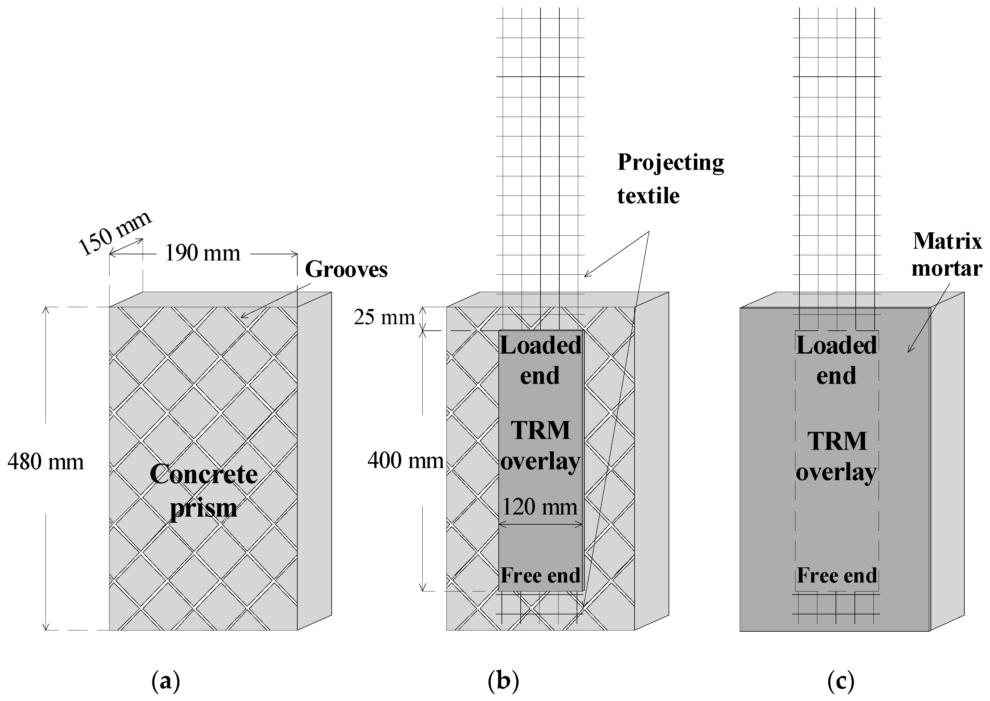
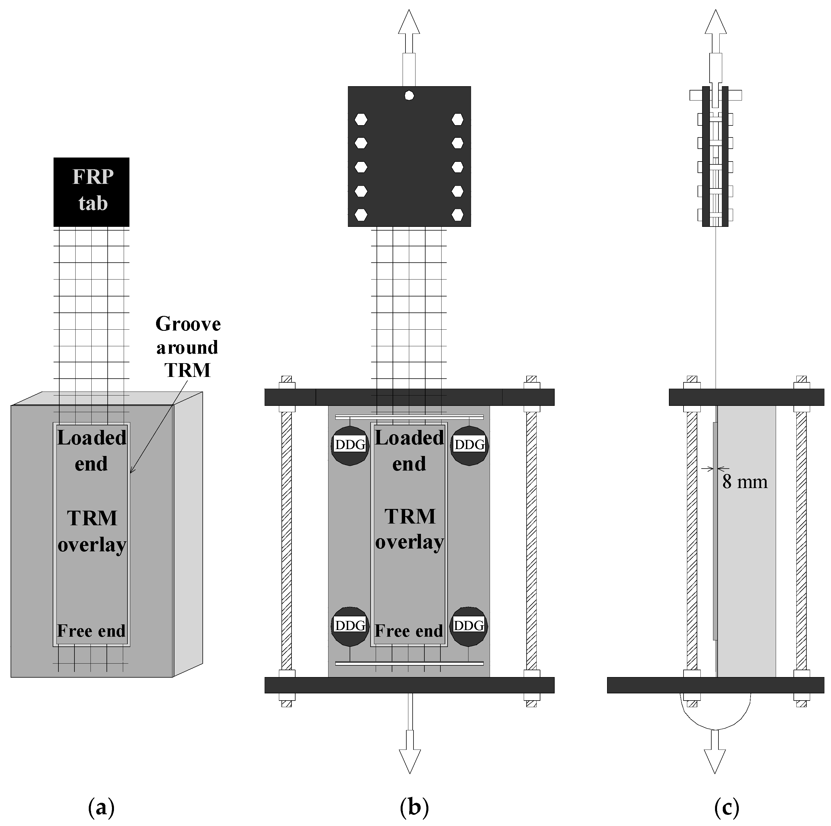
2.2. Bond Specimens
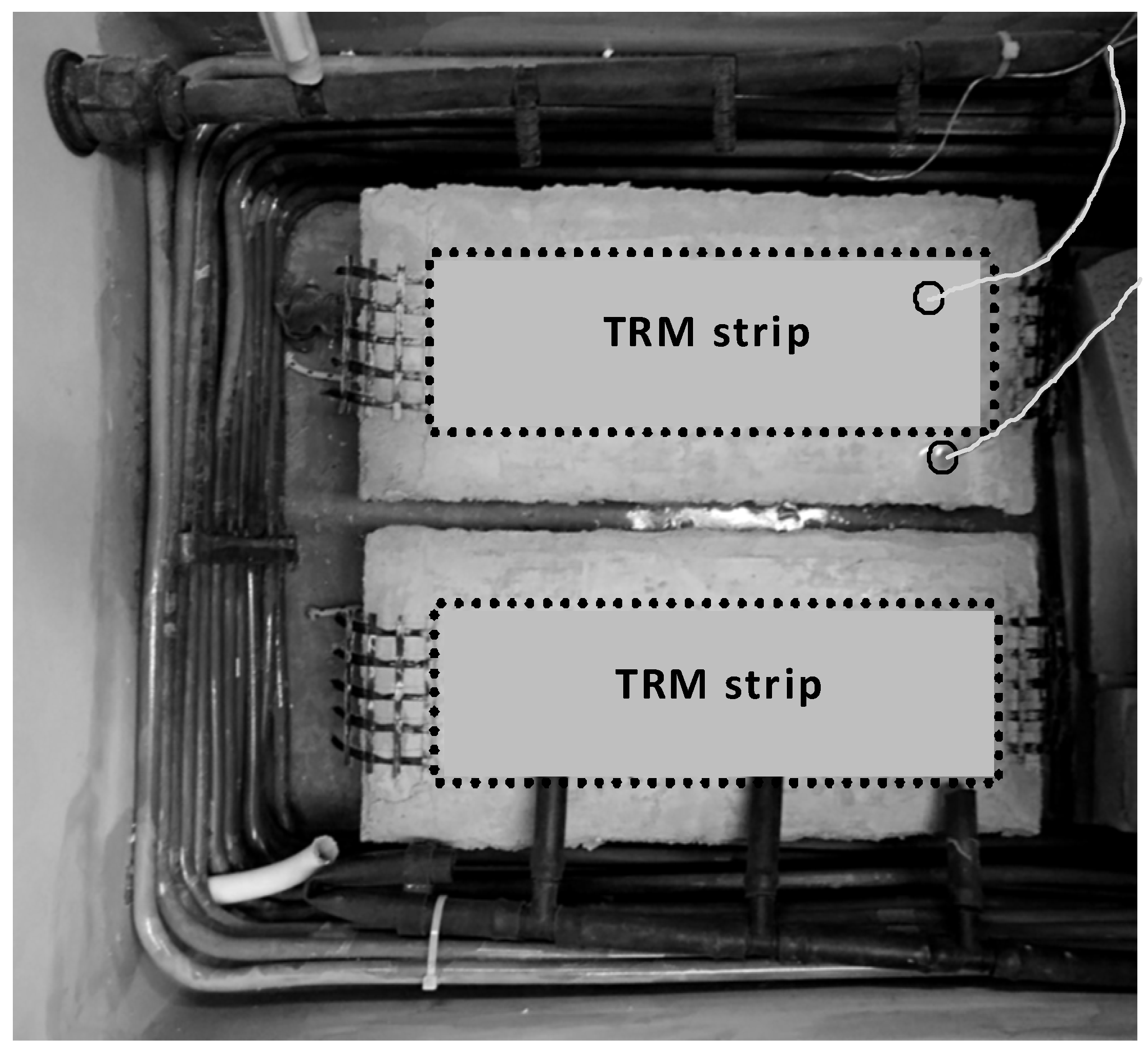
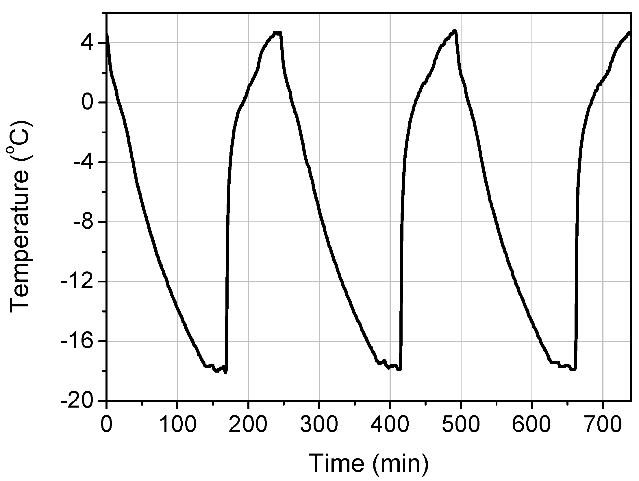
2.3. Hygro-Thermal Treatment
2.4. Shear Bond Test Set-Up
2.5. Experimental Program
3. Results
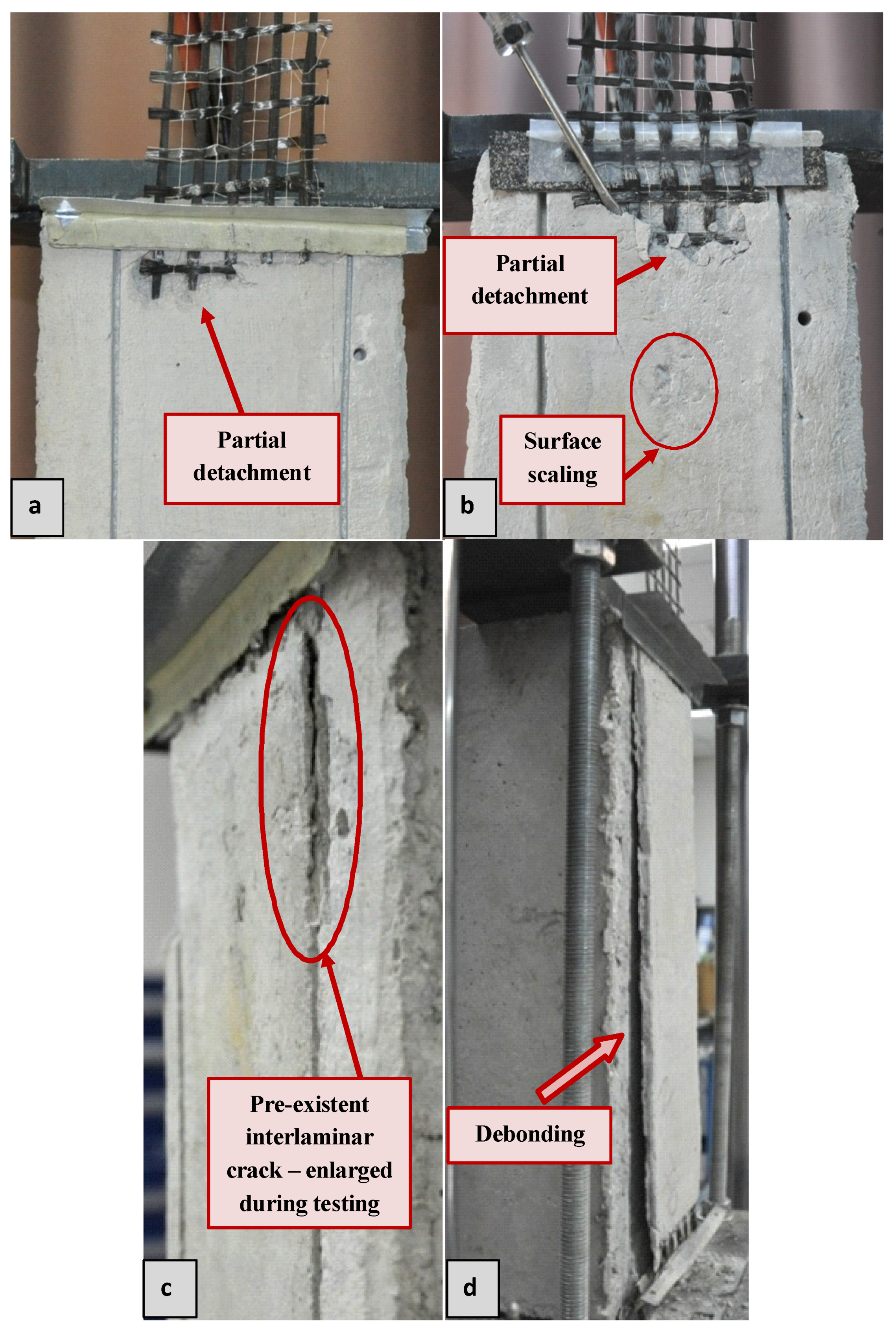
3.1. Failure Modes
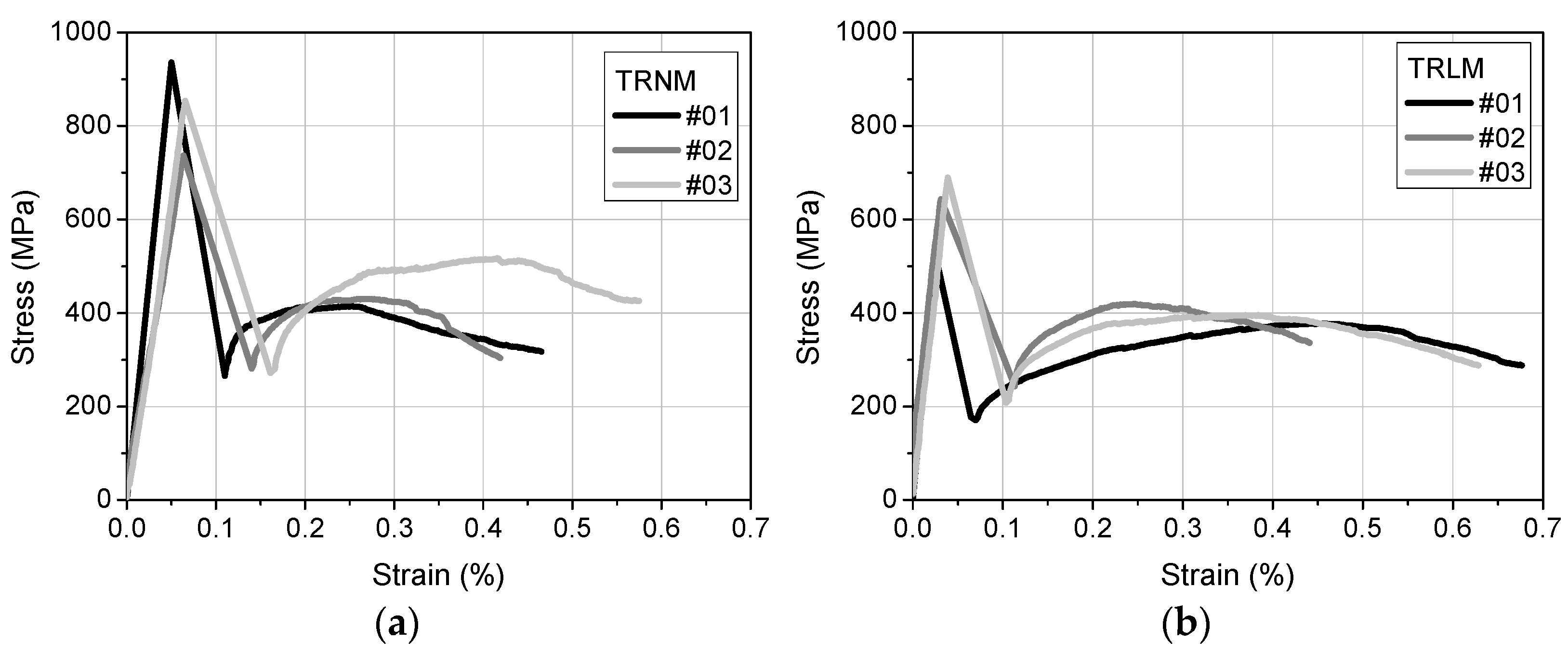
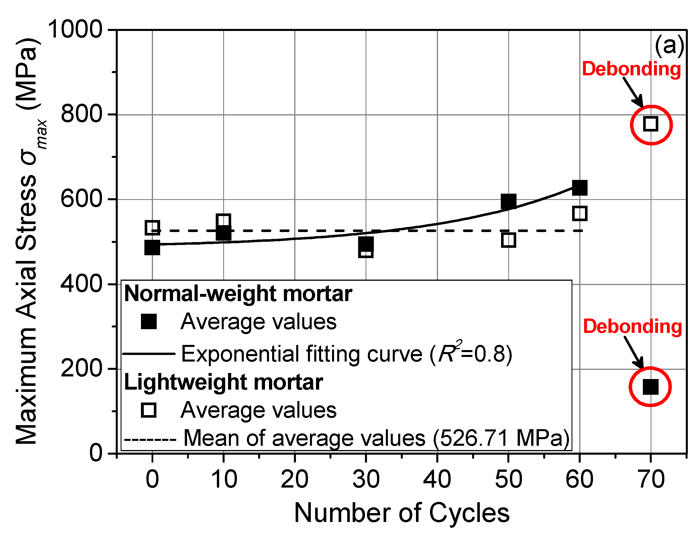
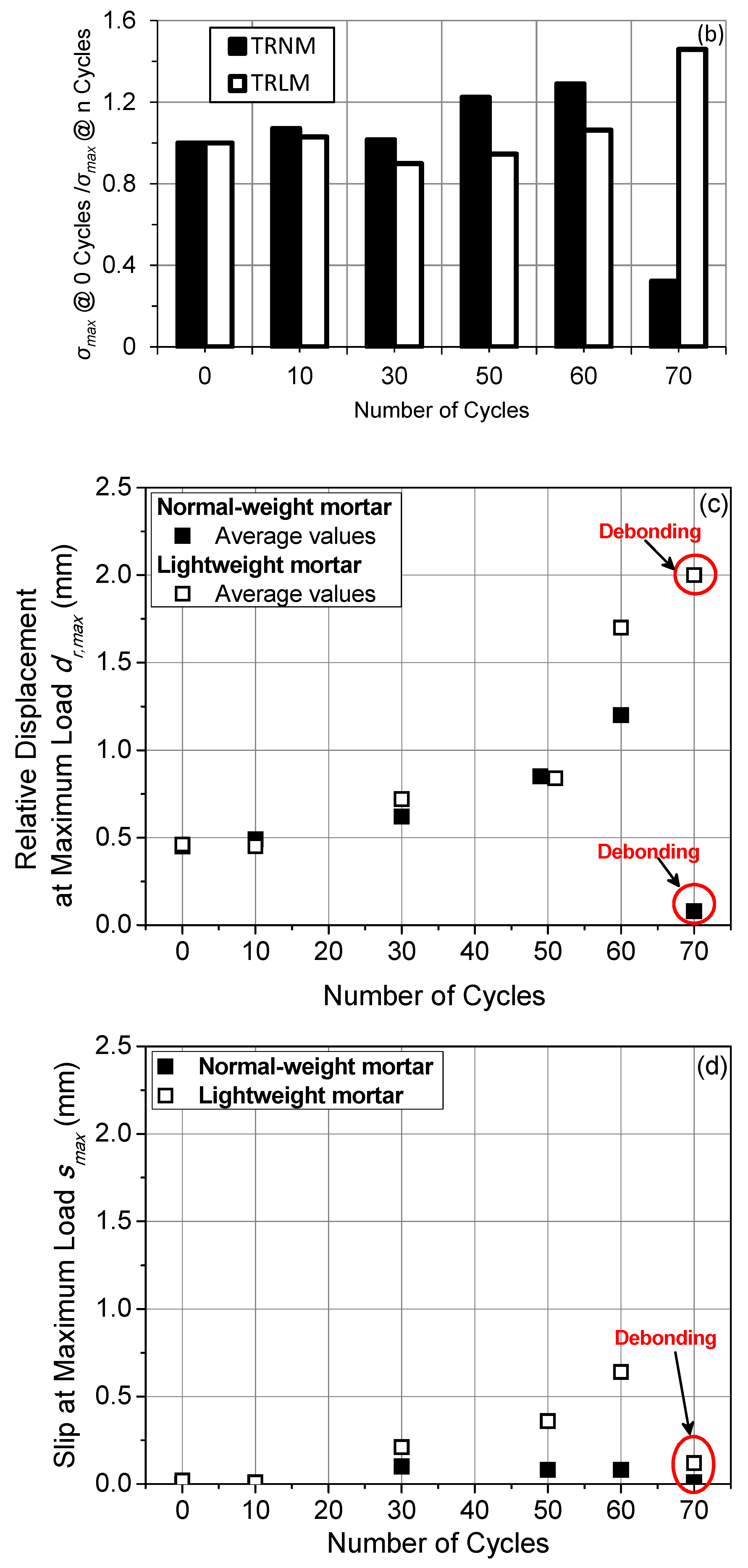
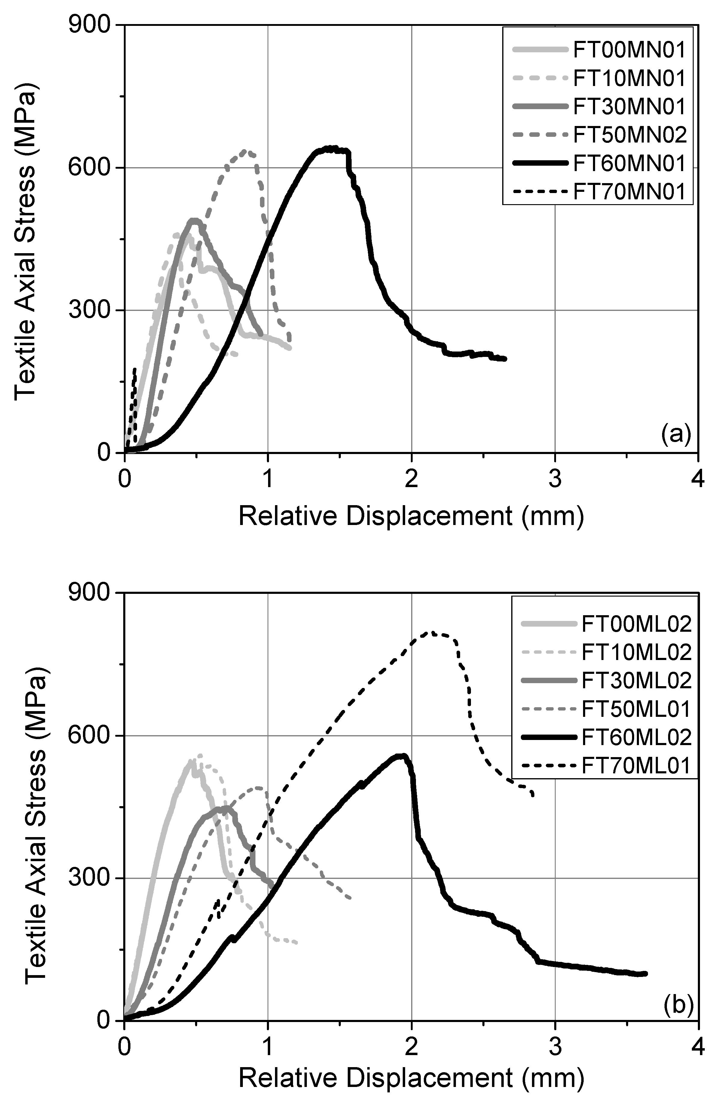
3.2. Specimens’ Response
4. Discussion
5. Conclusions
- All of the TRNM specimens (except for the ones subjected to 70 freeze–thaw cycles), control TRLM specimens, and TRLM specimens subjected to 10 freeze–thaw cycles failed due fiber rupture. The rest of the TRLM specimens (except for the ones subjected to 70 freeze–thaw cycles) failed due to the slippage of the textile from the mortar. This failure mode was also accompanied by the rupture of (a small number of) individual sleeve fibers. All of the specimens subjected to 70 freeze–thaw cycles failed due to the TRM debonding from the substrate.
- Two damage paths were identified: one through the textile protruding from the mortar both at the loaded and the free end and another through the top mortar layer.
- The damage processes did not have an adverse effect on the σmax values for all of the specimens subjected to up to 60 freeze–thaw cycles. The proposed explanation for this phenomenon can be the late hydration of the mortars, which was in dynamic antagonism with those of frost heaving.
- The frost damage of pumice-based mortars was heavier than the respective damage of limestone ones that had undergone up to 60 cycles. However, the benefits of late hydration became more prominent at longer exposure durations for the TRLM specimens in comparison with the TRNM ones (70 cycles), which was probably due to the slower late hydration evolution rate in the lightweight matrix.
Author Contributions
Funding
Institutional Review Board Statement
Informed Consent Statement
Data Availability Statement
Acknowledgments
Conflicts of Interest
References
- Raoof, S.M.; Koutas, L.N.; Bournas, D.A. Bond between textile-reinforced mortar (TRM) and concrete substrates: Experimental investigation. Compos. Part B Eng. 2016, 98, 350–361. [Google Scholar] [CrossRef]
- D’Ambrisi, A.; Feo, L.; Focacci, F. Experimental analysis on bond between PBO-FRCM strengthening materials and concrete. Compos. Part B Eng. 2013, 44, 524–532. [Google Scholar] [CrossRef]
- Al-Lami, K.; D’Antino, T.; Colombi, P. Durability of Fabric-Reinforced Cementitious Matrix (FRCM) Composites: A Review. Appl. Sci. 2020, 10, 1714. [Google Scholar] [CrossRef] [Green Version]
- Yin, S.-P.; Li, Y.; Jin, Z.-Y.; Li, P.-H. Interfacial Properties of Textile-Reinforced Concrete and Concrete in Chloride Freezing-and-Thawing Cycle. ACI Mater. J. 2018, 115, 197–208. [Google Scholar] [CrossRef]
- Al-Jaberi, Z.; Myers, J.J.; Chandrashekhara, K. Effect of direct service temperature exposure on the bond behavior between advanced composites and CMU using NSM and EB techniques. Compos. Struct. 2018, 211, 63–75. [Google Scholar] [CrossRef]
- Colombo, I.G.; Colombo, M.; di Prisco, M. Tensile behavior of textile reinforced concrete subjected to freezing–thawing cycles in un-cracked and cracked regimes. Cem. Concr. Res. 2015, 73, 169–183. [Google Scholar] [CrossRef]
- ASTM International. ASTM C666: Standard Test Method for Resistance of Concrete to Rapid Freezing and Thawing; ASTM International: West Conshohocken, PA, USA, 2015. [Google Scholar]
- Machovec, J.; Reiterman, P. Influence of aggressive environment on the tensile properties of textile reinforced concrete. Acta Polytech. 2018, 58, 245–252. [Google Scholar] [CrossRef]
- Nobili, A.; Signorini, C. On the effect of curing time and the environmental exposure on impregnated Carbon Fabric Rein-forced Cementitious Matrix (CFRCM) composite with design considerations. Compos. Part B Eng. 2017, 112, 300–313. [Google Scholar] [CrossRef] [Green Version]
- de Munk, M.; el Kadi, M.; Tsangouri, E.; Vervloet, J.; Verbruggen, S.; Wasties, J.; Tysmans, T.; Remy, O. Influence of environmental loading on the tensile and cracking behavior of textile reinforced cementitious composites. Constr. Build. Mater. 2018, 181, 325–334. [Google Scholar] [CrossRef]
- Belgisch instituut voor normalisatie (BIN). NBN EN 12467 Fibre Cement Flat Sheets—Product Specification and Test Methods, Toelating; Belgian Standards: Brussels, Belgium, 2007. [Google Scholar]
- Yin, S.; Jing, L.; Yin, M.; Wang, B. Mechanical properties of textile reinforced concrete under chloride wet-dry and freeze-thaw cycle environments. Cem. Concr. Compos. 2018, 96, 118–127. [Google Scholar] [CrossRef]
- Yin, S.-P.; Na, M.-W.; Yu, Y.-L.; Wu, J. Research on the flexural performance of RC beams strengthened with TRC under the coupling action of load and marine environment. Constr. Build. Mater. 2017, 132, 251–261. [Google Scholar] [CrossRef]
- CEN. EN ISO 13934-1: Textiles-Tensile Properties of Fabrics–Part 1: Determination of Maximum Force and Elongation at Maximum Force Using the Strip Method; British Standard: Brussels, Belgium, 1999. [Google Scholar]
- CEN. EN 1015-11: Methods of Test for Mortar for Masonry–Part 11: Determination of Flexural and Compressive Strength of Hardened Mortar; European Committee for Standardization: Brussels, Belgium, 1993. [Google Scholar]
- CEN. EN 1015-3 + A1: Methods of Test for Mortar for Masonry–Part 3: Determination of Consistence of Fresh Mortar (by Flow Table) (Includes Amendment A1:2004); European Committee for Standardization: Brussels, Belgium, 1999. [Google Scholar]
- International Code Council Evaluation Services. AC434 ICC-ES: Masonry and Concrete Strengthening Using Fiber-Reinforced Cementitious Matrix (FRCM) Composite Systems; ICC-Evaluation Service: Whittier, CA, USA, 2013. [Google Scholar]
- D’Antino, T.; Gonzalez, J.; Pellegrino, C.; Carloni, C.; Sneed, L.H. Experimental Investigation of Glass and Carbon FRCM Composite Materials Applied onto Concrete Supports. Appl. Mech. Mater. 2016, 847, 60–67. [Google Scholar] [CrossRef]
- Askouni, P.D.; Papanicolaou, C.G. Experimental investigation of bond between glass textile reinforced mortar overlays and masonry: The effect of bond length. Mater. Struct. 2017, 50, 164. [Google Scholar] [CrossRef]
- Sabau, C.; Gonzalez-Libreros, J.H.; Sneed, L.H.; Sas, G.; Pellegrino, C.; Täljsten, B. Use of image correlation system to study the bond behavior of FRCM-concrete joints. Mater. Struct. 2017, 50, 1. [Google Scholar] [CrossRef]
- De Felice, G.; Aiello, M.A.; Caggegi, C.; Ceroni, F.; De Santis, S.; Garbin, E.; Gattesco, N.; Hojdys, Ł.; Krajewski, P.; Kwiecień, A.; et al. Recommendation of RILEM Technical Committee 250-CSM: Test method for Textile Reinforced Mortar to substrate bond characterization. Mater. Struct. 2018, 51, 95. [Google Scholar] [CrossRef]
- Sokhansefat, G.; Moradian, M.; Finnell, M.; Behravan, A.; Ley, M.T.; Lucero, C.; Weiss, J. Using X-ray computed tomography to investigate mortar subjected to freeze-thaw cycles. Cem. Concr. Compos. 2020, 108, 103520. [Google Scholar] [CrossRef]
- Soroushian, P.; Nagi, M.; Okwuegbu, A. Freeze−Thaw durability of lightweight carbon fiber reinforced cement composites. ACI Mater. J. 1992, 89, 491–494. [Google Scholar]


| Matrix | Normal-Weight | Lightweight |
|---|---|---|
| Composition | ||
| Portland cement (CEM II 42.5N) | 586 kg/m3 | 610 kg/m3 |
| Sand (dmax = 2 mm) * | 1024 (limestone) kg/m3 | 550 (pumice) kg/m3 |
| Silica fume (dmax = 1 μm) | 47 kg/m3 | 49 kg/m3 |
| Limestone filler (dmax = 120 μm) | 146 kg/m3 | 152 kg/m3 |
| Effective water ** | 344 kg/m3 | 316 kg/m3 |
| Water to cementitious materials | 0.54 | 0.48 |
| Air content | 1.9% (by vol.) | 1.2% (by vol.) |
| Fresh mortar flow value [16] | 14.5 mm | 13.7 mm |
| Specimen | Number of Freeze–Thaw Cycles | σmax (MPa) | σmax,average (MPa) {CoV} | dr,max (mm) | dr,max,average (mm) {CoV} | smax (mm) | Failure Mode * |
|---|---|---|---|---|---|---|---|
| FT0MN01 | 0 | 457.95 | 486.71 | 0.45 | - | 0.00 | FR |
| FT0MN02 | 0 | 515.47 | {8%} | - ** | - | FR | |
| FT10MN01 | 10 | 459.29 | 521.14 | 0.37 | 0.49 | 0.01 | FR-PD |
| FT10MN02 | 10 | 582.99 | {17%} | 0.61 | {35%} | FR-PD | |
| FT30MN01 | 30 | 489.20 | 494.43 | 0.49 | 0.62 | 0.10 | FR-PD |
| FT30MN02 | 30 | 499.66 | {1%} | 0.75 | {30%} | FR-PD | |
| FT50MN01 | 50 | 554.96 | 595.70 | - ** | - | 0.08 | FR-PD |
| FT50MN02 | 50 | 636.44 | {10%} | 0.85 | - | FR-PD | |
| FT60MN01 | 60 | 641.73 | 627.76 | 1.43 | 1.20 | 0.08 | FR-PDPIC |
| FT60MN02 | 60 | 613.79 | {3%} | 0.98 | {27%} | FR-PDPIC | |
| FT70MN01 | 70 | 176.18 | 157.23 | 0.07 | 0.08 | 0.01 | DPIC |
| FT70MN02 | 70 | 138.28 | {17%} | 0.09 | {19%} | DPIC | |
| FT0ML01 | 0 | 524.72 | 533.31 | - ** | - | 0.02 | FR |
| FT0ML02 | 0 | 541.91 | {2%} | 0.46 | - | FR | |
| FT10ML01 | 10 | 539.18 | 549.25 | 0.37 | 0.45 | 0.01 | FR-PD |
| FT10ML02 | 10 | 559.32 | {3%} | 0.53 | {25%} | FR-PD | |
| FT30ML01 | 30 | 511.29 | 479.72 | - ** | - | 0.21 | TS-PD |
| FT30ML02 | 30 | 448.15 | {9%} | 0.72 | - | TS-PD | |
| FT50ML01 | 50 | 490.57 | 504.24 | 0.92 | 0.84 | 0.36 | TS-PDPIC |
| FT50ML02 | 50 | 517.90 | {4%} | 0.77 | {13%} | TS-PDPIC | |
| FT60ML01 | 60 | 576.17 | 567.03 | 1.44 | 1.70 | 0.64 | TS-PDPIC |
| FT60ML02 | 60 | 557.89 | {2%} | 1.95 | {21%} | TS-PDPIC | |
| FT70ML01 | 70 | 820.12 | 778.08 | 2.13 | 2.00 | 0.12 | DPIC |
| FT70ML02 | 70 | 736.05 | {8%} | 1.87 | {9%} | DPIC |
Publisher’s Note: MDPI stays neutral with regard to jurisdictional claims in published maps and institutional affiliations. |
© 2021 by the authors. Licensee MDPI, Basel, Switzerland. This article is an open access article distributed under the terms and conditions of the Creative Commons Attribution (CC BY) license (https://creativecommons.org/licenses/by/4.0/).
Share and Cite
Askouni, P.D.; Papanicolaou, C.G. Residual TRM-to-Concrete Bond after Freeze–Thaw Cycles. Materials 2021, 14, 5438. https://doi.org/10.3390/ma14185438
Askouni PD, Papanicolaou CG. Residual TRM-to-Concrete Bond after Freeze–Thaw Cycles. Materials. 2021; 14(18):5438. https://doi.org/10.3390/ma14185438
Chicago/Turabian StyleAskouni, Paraskevi D., and Catherine (Corina) G. Papanicolaou. 2021. "Residual TRM-to-Concrete Bond after Freeze–Thaw Cycles" Materials 14, no. 18: 5438. https://doi.org/10.3390/ma14185438