
Architecture-Promoted Biomechanical Performance-Tuning of Tissue-Engineered Constructs for Biological Intervertebral Disc Replacement

 ,
,  , , , and
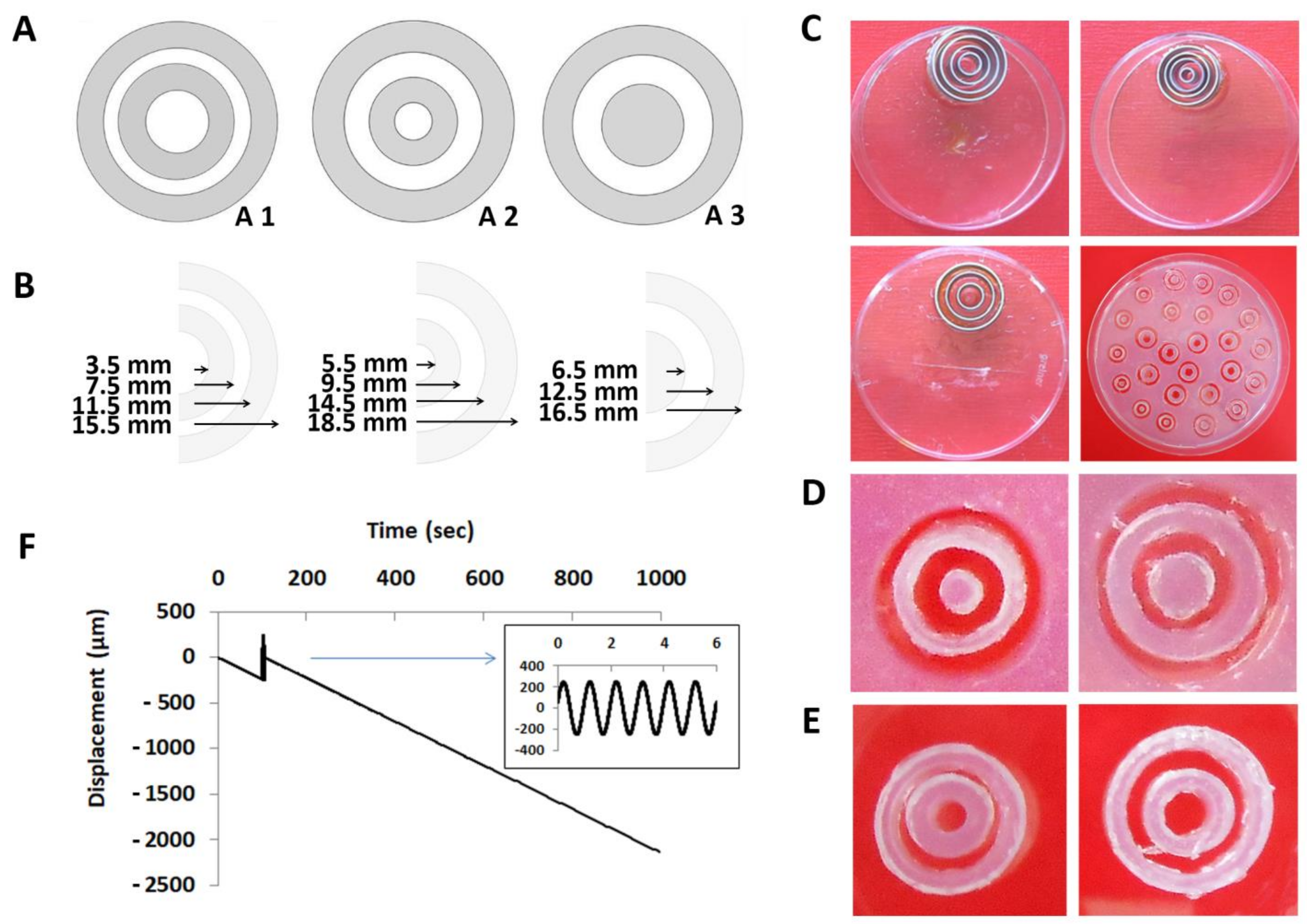
Abstract
:1. Introduction
2. Materials and Methods
2.1. Model System Architectural Design
2.2. Model System Biomaterials
2.2.1. Agarose
2.2.2. Gelatin
2.3. Model System Fabrication
2.4. Model System Mechanical Characterization
2.5. Gelatin Degradation Behavior
2.6. Cell Isolation and Culture
2.7. Caffeic Acid-Crosslinked Gelatin Cytotoxicity
2.8. Model System Architecture 1 from 5% Agarose and a Chondron-Seeded Dextran Hydrogel
2.9. Live-Dead Imaging
2.10. Statistical Analysis
3. Results
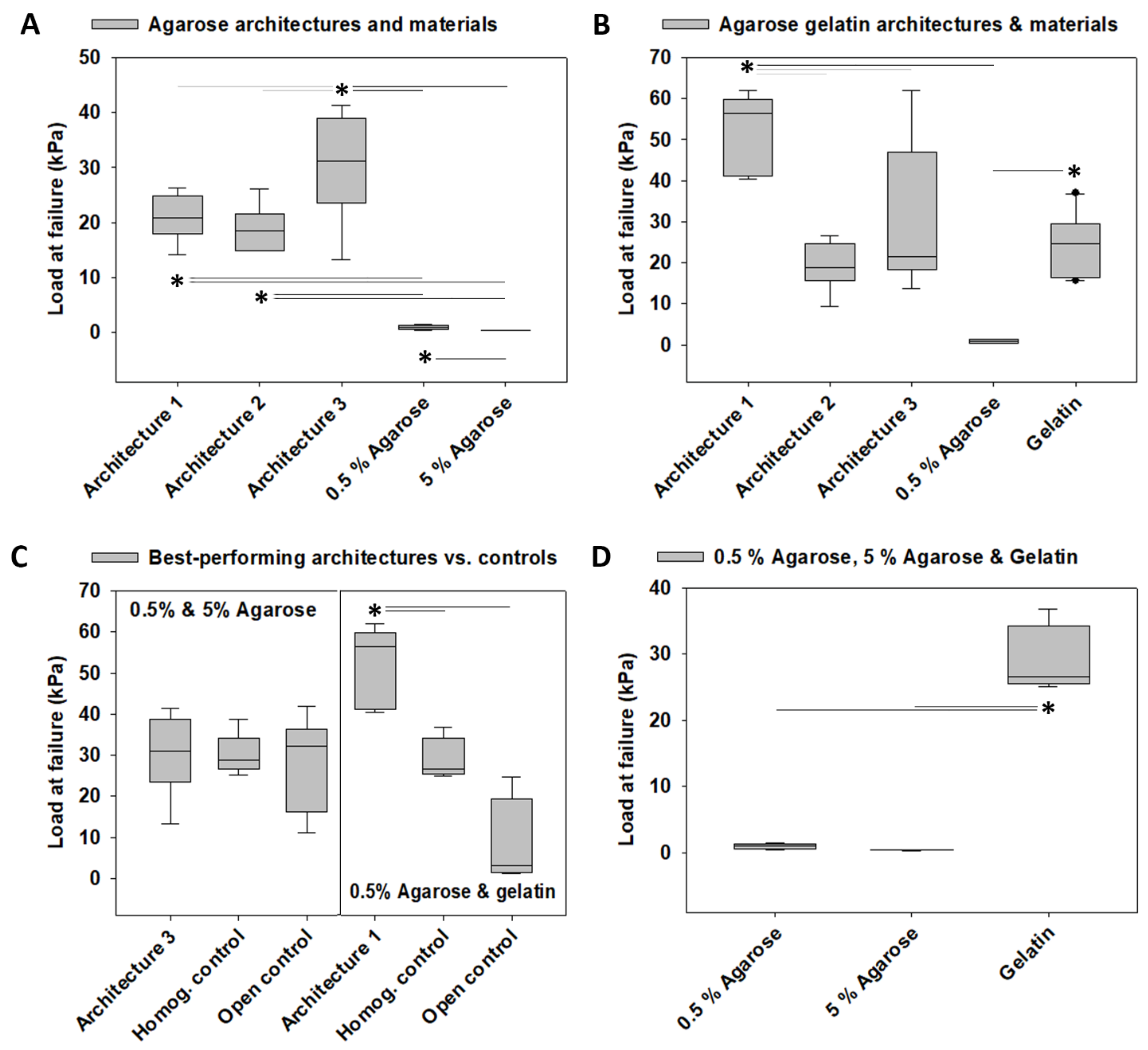
3.1. Load at Failure
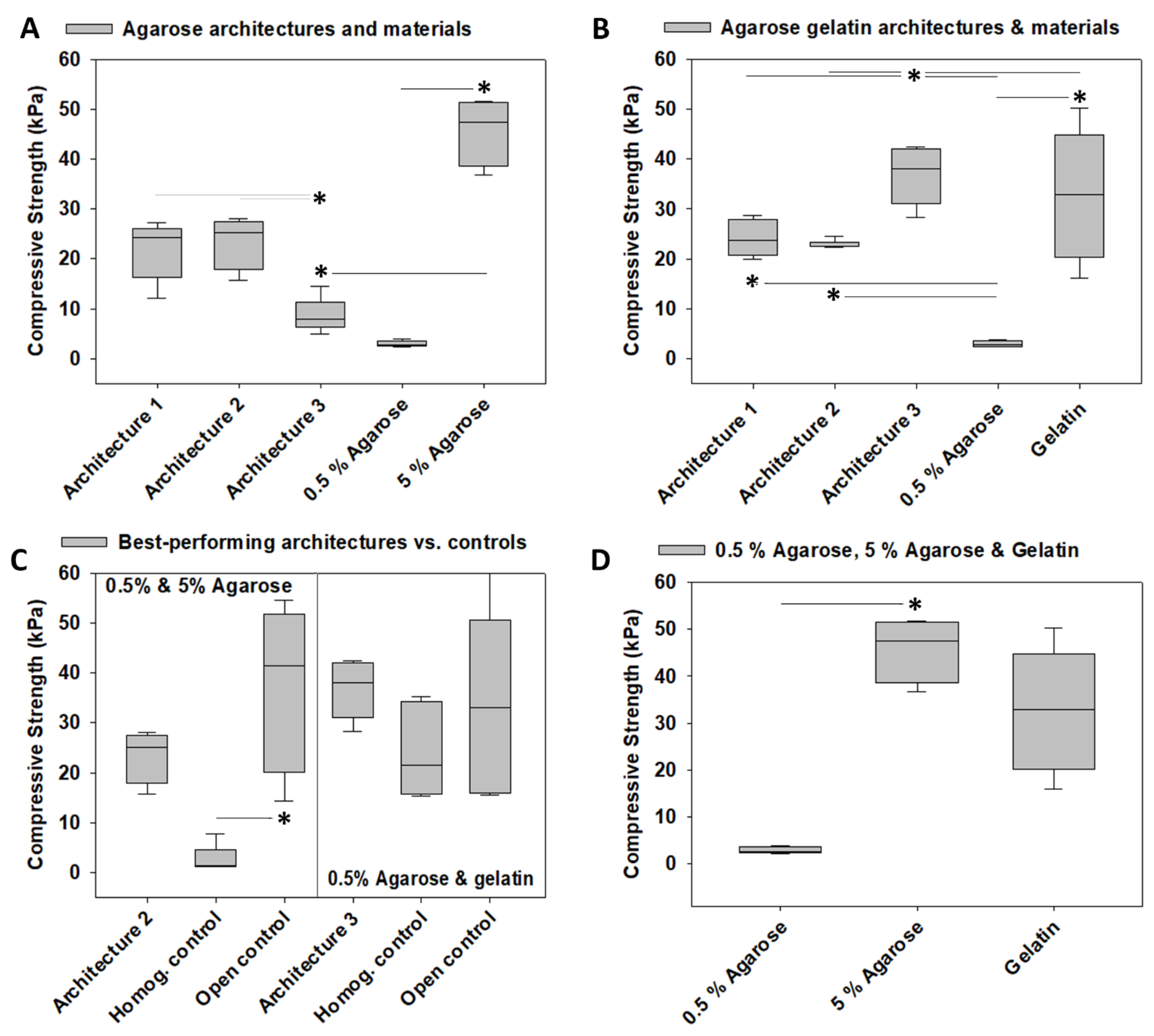
3.2. Compressive Strength
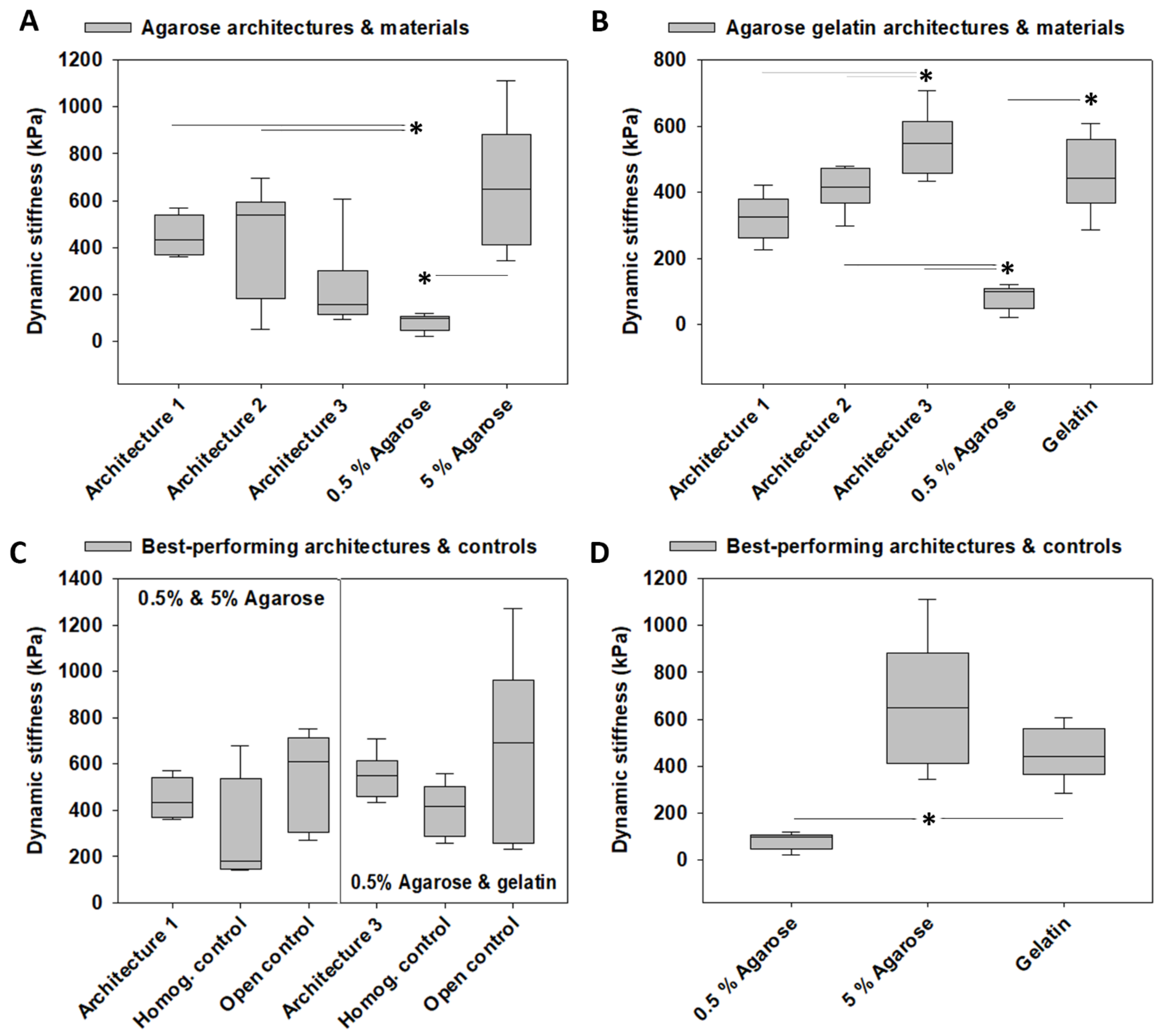
3.3. Dynamic Stiffness
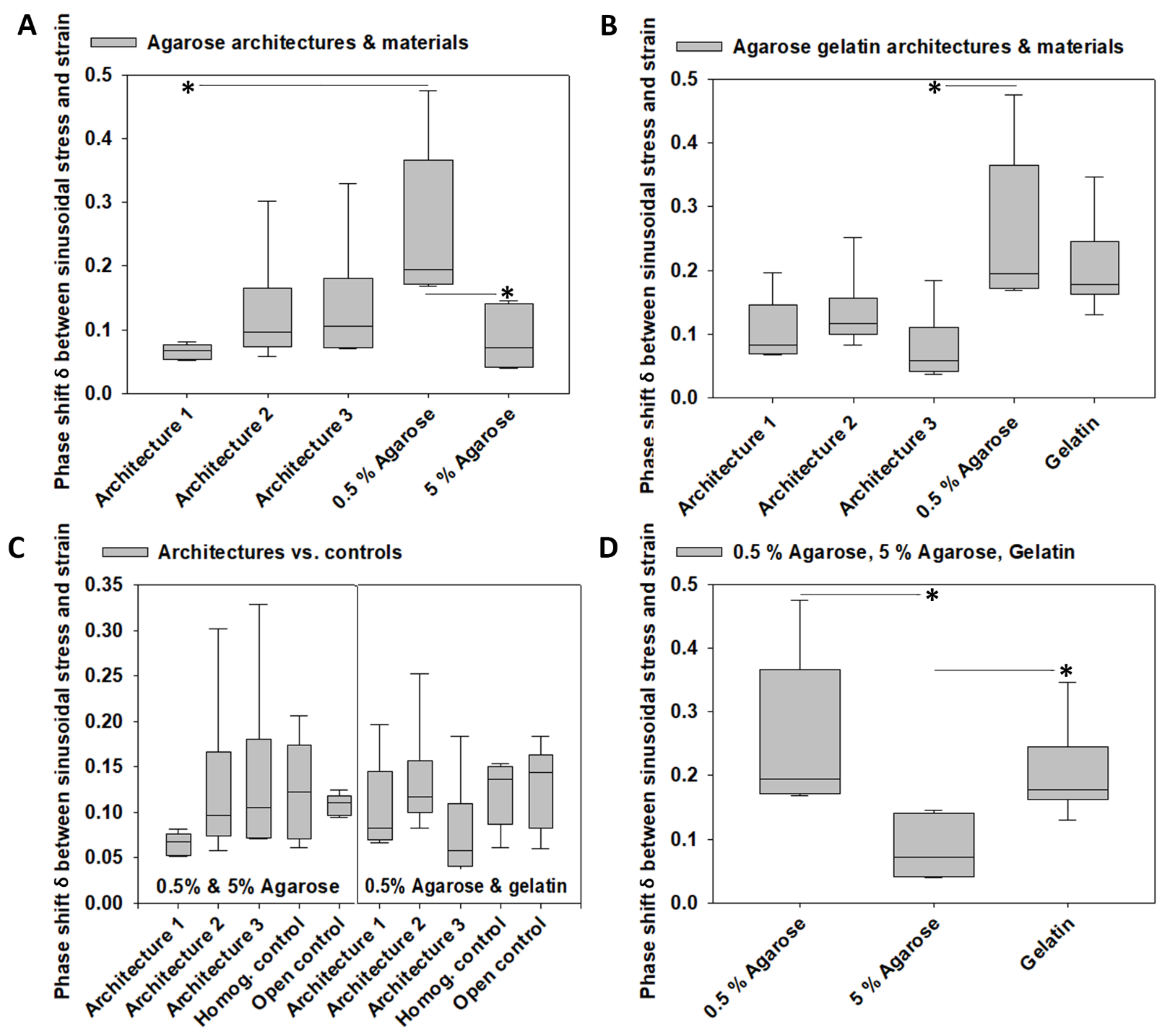
3.4. Viscoelastic Properties
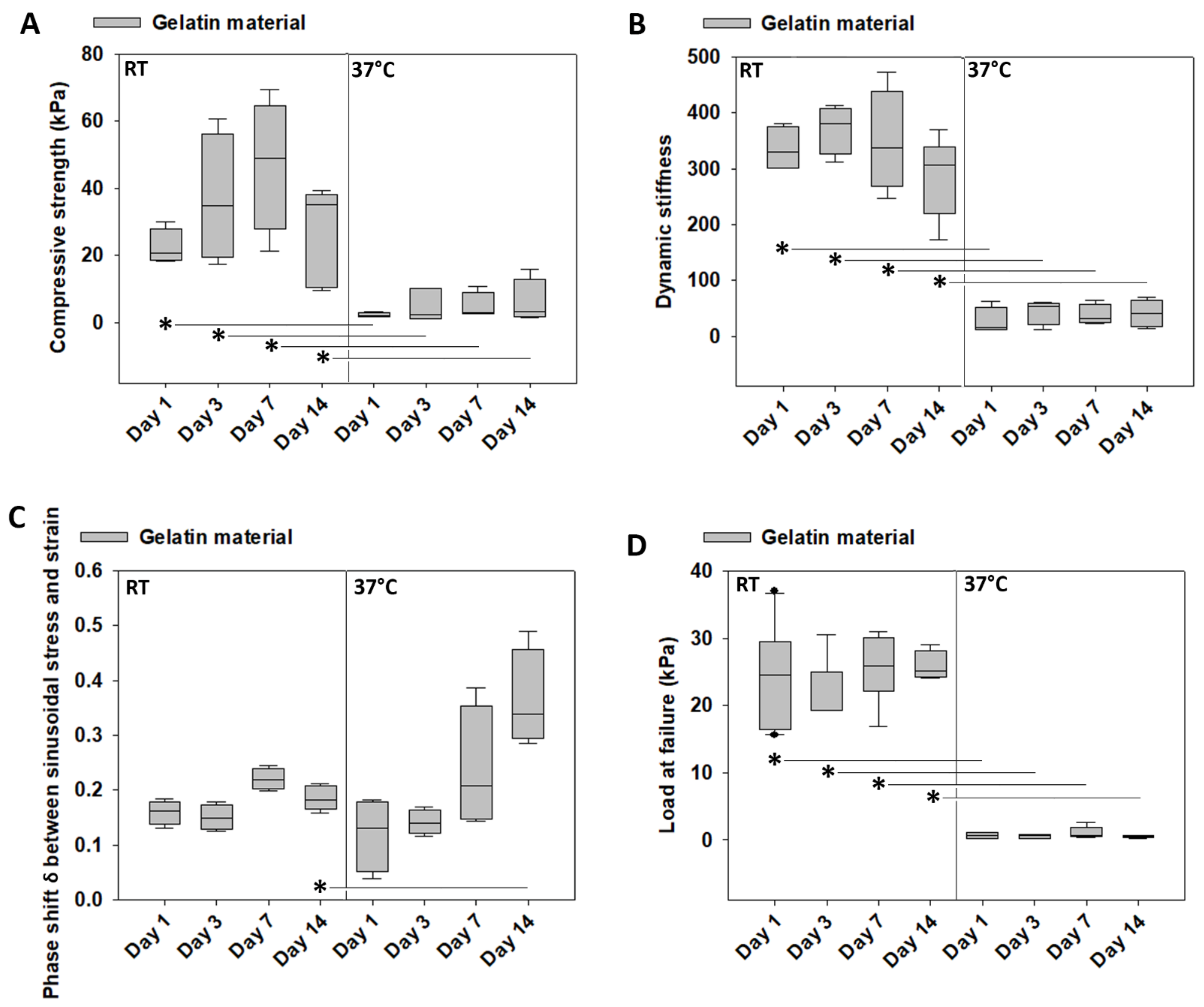
3.5. Mechanical Characterization of Gelatin over Time at Room Temperature vs. 37 °C
3.6. Weight Loss of Gelatin over Time at Room Temperature vs. 37 °C
3.7. Cytotoxicity Tests of Gelatin Crosslinked by Caffeic Acid
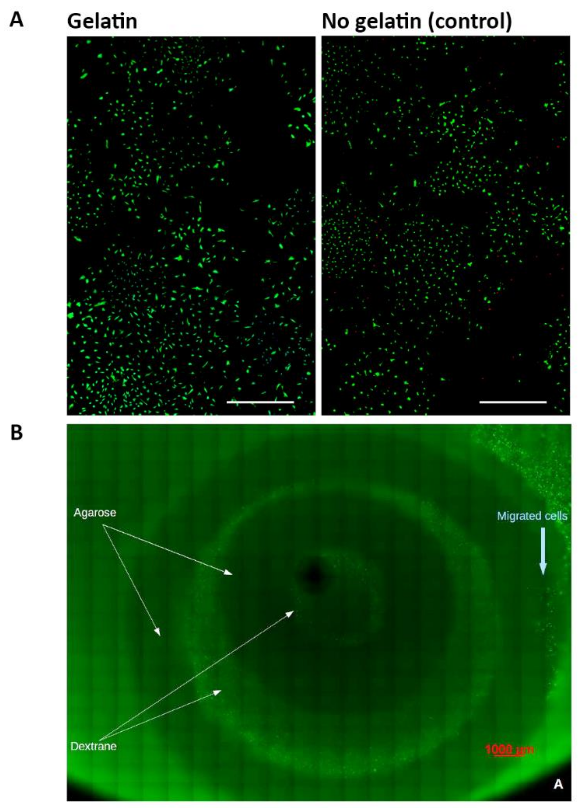
3.8. Architecture 1 Fabricated from Agarose and a Dextran-Based Hydrogel Seeded with Human Chondrons
4. Discussion
4.1. Architecture-Promoted Biomechanical Performance-Tuning of Tissue-Engineered Constructs
4.2. Material-Independent and Architecture-Dependent Modulation of the Mechanical Properties of TE Constructs
4.3. The Effect of the AF-Like Lamellar Structure on the Mechanical Performance of TE IVD Constructs
4.4. AF Fiber Re-Enforcement
4.5. Biocompatibility of TE IVD Constructs
4.6. Strengths and Limitations
5. Conclusions
Supplementary Materials
Author Contributions
Funding
Institutional Review Board Statement
Informed Consent Statement
Data Availability Statement
Acknowledgments
Conflicts of Interest
References
- Harmon, M.D. Growing a backbone-functional biomaterials and structures for intervertebral disc (IVD) repair and regeneration: Challenges, innovations, and future directions. Biomater. Sci. 2020, 8, 1216–1239. [Google Scholar] [CrossRef]
- Huang, Y.-C.; Hu, Y.; Li, Z.; Luk, K.D.K. Biomaterials for intervertebral disc regeneration: Current status and looming challenges. J. Tissue Eng. Regen. Med. 2018, 12, 2188–2202. [Google Scholar] [CrossRef] [PubMed]
- Buckley, C.T.; Hoyland, J.A.; Fujii, K.; Pandit, A.; Iatridis, J.C.; Grad, S. Critical aspects and challenges for intervertebral disc repair and regeneration-Harnessing advances in tissue engineering. JOR Spine 2018, 1, e1029. [Google Scholar] [CrossRef] [PubMed] [Green Version]
- Neidlinger-Wilke, C.; Galbusera, F.; Pratsinis, H.; Mavrogonatou, E.; Mietsch, A.; Kletsas, D.; Wilke, H.-J. Mechanical loading of the intervertebral disc: From the macroscopic to the cellular level. Eur. Spine J. 2014, 23, 333–343. [Google Scholar] [CrossRef] [PubMed]
- Nerurkar, N.L.; Elliott, D.M.; Mauck, R.L. Mechanical design criteria for intervertebral disc tissue engineering. J. Biomech. 2010, 43, 1017–1030. [Google Scholar] [CrossRef] [PubMed] [Green Version]
- Iatridis, J.C.; MacLean, J.J.; O’Brien, M.; Stokes, I.A.F. Measurements of proteoglycan and water content distribution in human lumbar intervertebral discs. Spine 2007, 32, 1493–1497. [Google Scholar] [CrossRef] [PubMed]
- Sakai, D.; Nakai, T.; Mochida, J.; Alini, M.; Grad, S. Differential phenotype of intervertebral disc cells: Microarray and immunohistochemical analysis of canine nucleus pulposus and anulus fibrosus. Spine 2009, 34, 1448–1456. [Google Scholar] [CrossRef]
- Pezowicz, C.A.; Robertson, P.A.; Broom, N.D. Intralamellar relationships within the collagenous architecture of the annulus fibrosus imaged in its fully hydrated state. J. Anat. 2005, 207, 299–312. [Google Scholar] [CrossRef]
- Schollum, M.L.; Robertson, P.A.; Broom, N.D. A microstructural investigation of intervertebral disc lamellar connectivity: Detailed analysis of the translamellar bridges. J. Anat. 2009, 214, 805–816. [Google Scholar] [CrossRef]
- Tavakoli, J.; Costi, J.J. New insights into the viscoelastic and failure mechanical properties of the elastic fiber network of the inter-lamellar matrix in the annulus fibrosus of the disc. Acta Biomater. 2018, 77, 292–300. [Google Scholar] [CrossRef]
- Vos, T.; Abajobir, A.A.; Abate, K.H.; Abbafati, C.; Abbas, K.M.; Abd-Allah, F.; Abdulkader, R.S.; Abdulle, A.M.; Abebo, T.A.; Abera, S.F.; et al. Global, regional, and national incidence, prevalence, and years lived with disability for 328 diseases and injuries for 195 countries, 1990–2016: A systematic analysis for the Global Burden of Disease Study 2016. Lancet 2017, 390, 1211–1259. [Google Scholar] [CrossRef] [Green Version]
- Brodke, D.S.; Ritter, S.M. Nonsurgical management of low back pain and lumbar disk degeneration. Instr. Course Lect. 2005, 54, 279–286. [Google Scholar]
- Gangl, M. Spezifischer Kreuzschmerz–die erste Leitlinie. Man. Med. 2020, 58, 46–52. [Google Scholar] [CrossRef]
- Findlay, C.; Ayis, S.; Demetriades, A.K. Total disc replacement versus anterior cervical discectomy and fusion: A systematic review with meta-analysis of data from a total of 3160 patients across 14 randomized controlled trials with both short- and medium- to long-term outcomes. Bone Jt. J. 2018, 100-B, 991–1001. [Google Scholar] [CrossRef]
- Wahood, W.; Yolcu, Y.U.; Kerezoudis, P.; Goyal, A.; Alvi, M.A.; Freedman, B.A.; Bydon, M. Artificial Discs in Cervical Disc Replacement: A Meta-Analysis for Comparison of Long-Term Outcomes. World Neurosurg. 2020, 134, 598–613.e5. [Google Scholar] [CrossRef]
- Kim, D.H.; Martin, J.T.; Gullbrand, S.E.; Elliott, D.M.; Smith, L.J.; Smith, H.E.; Mauck, R.L. Fabrication, maturation, and implantation of composite tissue-engineered total discs formed from native and mesenchymal stem cell combinations. Acta Biomater. 2020, 114, 53–62. [Google Scholar] [CrossRef]
- Mojica-Santiago, J.A.; Lang, G.M.; Navarro-Ramirez, R.; Hussain, I.; Härtl, R.; Bonassar, L.J. Resorbable plating system stabilizes tissue-engineered intervertebral discs implanted ex vivo in canine cervical spines. JOR Spine 2018, 1, e1031. [Google Scholar] [CrossRef]
- Ruan, D.; He, Q.; Ding, Y.; Hou, L.; Li, J.; Luk, K.D. Intervertebral disc transplantation in the treatment of degenerative spine disease: A preliminary study. Lancet 2007, 369, 993–999. [Google Scholar] [CrossRef]
- Shaha, R.K.; Merkel, D.R.; Anderson, M.P.; Devereaux, E.J.; Patel, R.R.; Torbati, A.H.; Willett, N.; Yakacki, C.M.; Frick, C.P. Biocompatible liquid-crystal elastomers mimic the intervertebral disc. J. Mech. Behav. Biomed. Mater. 2020, 107, 103757. [Google Scholar] [CrossRef]
- Sloan, S.R.; Wipplinger, C.; Kirnaz, S.; Navarro-Ramirez, R.; Schmidt, F.; McCloskey, D.; Pannellini, T.; Schiavinato, A.; Härtl, R.; Bonassar, L.J. Combined nucleus pulposus augmentation and annulus fibrosus repair prevents acute intervertebral disc degeneration after discectomy. Sci. Transl. Med. 2020, 12, eaay2380. [Google Scholar] [CrossRef]
- Mannion, A.F. EUROSPINE 2017 FULL PAPER AWARD: Time to remove our rose-tinted spectacles: A candid appraisal of the relative success of surgery in over 4500 patients with degenerative disorders of the lumbar spine, hip or knee. Eur. Spine J. 2018, 27, 778–788. [Google Scholar] [CrossRef] [PubMed]
- Rustenburg, C.M.E.; Faraj, S.S.A.; Ket, J.C.F.; Emanuel, K.S.; Smit, T.H. Prognostic factors in the progression of intervertebral disc degeneration: Which patient should be targeted with regenerative therapies? JOR Spine 2019, 2, 3. [Google Scholar] [CrossRef] [PubMed]
- Smith, L.J.; Silverman, L.; Sakai, D.; Le Maitre, C.L.; Mauck, R.L.; Malhotra, N.R.; Lotz, J.C.; Buckley, C.T. Advancing cell therapies for intervertebral disc regeneration from the lab to the clinic: Recommendations of the ORS spine section. JOR Spine 2018, 1, e1036. [Google Scholar] [CrossRef]
- Li, Z.; Lang, G.; Chen, X.; Sacks, H.; Mantzur, C.; Tropp, U.; Mader, K.T.; Smallwood, T.C.; Sammon, C.; Richards, R.G.; et al. Polyurethane scaffold with in situ swelling capacity for nucleus pulposus replacement. Biomaterials 2016, 84, 196–209. [Google Scholar] [CrossRef] [PubMed]
- Li, Z.; Lang, G.; Karfeld-Sulzer, L.S.; Mader, K.T.; Richards, R.G.; Weber, F.E.; Sammon, C.; Sacks, H.; Yayon, A.; Alini, M.; et al. Heterodimeric BMP-2/7 for nucleus pulposus regeneration-In vitro and ex vivo studies: BMP-2/7 FOR NUCLEUS PULPOSUS REGENERATION. J. Orthop. Res. 2017, 35, 51–60. [Google Scholar] [CrossRef] [PubMed] [Green Version]
- Pennicooke, B.; Hussain, I.; Berlin, C.; Sloan, S.R.; Borde, B.; Moriguchi, Y.; Lang, G.; Navarro-Ramirez, R.; Cheetham, J.; Bonassar, L.J.; et al. Annulus Fibrosus Repair Using High-Density Collagen Gel: An In Vivo Ovine Model. Spine 2018, 43, E208–E215. [Google Scholar] [CrossRef] [PubMed]
- Bron, J.L.; Vonk, L.A.; Smit, T.H.; Koenderink, G.H. Engineering alginate for intervertebral disc repair. J. Mech. Behav. Biomed. Mater. 2011, 4, 1196–1205. [Google Scholar] [CrossRef]
- Frauchiger, D.A.; May, R.D.; Bakirci, E.; Tekari, A.; Chan, S.C.W.; Wöltje, M.; Benneker, L.M.; Gantenbein, B. Genipin-Enhanced Fibrin Hydrogel and Novel Silk for Intervertebral Disc Repair in a Loaded Bovine Organ Culture Model. J. Funct. Biomater. 2018, 9, 3. [Google Scholar] [CrossRef] [Green Version]
- Lee, K.-I.; Moon, S.-H.; Kim, H.; Kwon, U.-H.; Kim, H.-J.; Park, S.-N.; Suh, H.; Lee, H.-M.; Kim, H.-S.; Chun, H.-J.; et al. Tissue engineering of the intervertebral disc with cultured nucleus pulposus cells using atelocollagen scaffold and growth factors. Spine 2012, 37, 452–458. [Google Scholar] [CrossRef]
- Abbushi, A.; Endres, M.; Cabraja, M.; Kroppenstedt, S.N.; Thomale, U.W.; Sittinger, M.; Hegewald, A.A.; Morawietz, L.; Lemke, A.-J.; Bansemer, V.-G.; et al. Regeneration of intervertebral disc tissue by resorbable cell-free polyglycolic acid-based implants in a rabbit model of disc degeneration. Spine 2008, 33, 1527–1532. [Google Scholar] [CrossRef]
- Alinejad, Y.; Adoungotchodo, A.; Grant, M.P.; Epure, L.M.; Antoniou, J.; Mwale, F.; Lerouge, S. Injectable Chitosan Hydrogels with Enhanced Mechanical Properties for Nucleus Pulposus Regeneration. Tissue Eng Part A 2019, 25, 303–313. [Google Scholar] [CrossRef]
- Ruan, D.-K.; Xin, H.; Zhang, C.; Wang, C.; Xu, C.; Li, C.; He, Q. Experimental intervertebral disc regeneration with tissue-engineered composite in a canine model. Tissue Eng. Part A 2010, 16, 2381–2389. [Google Scholar] [CrossRef]
- Huang, B.; Zhuang, Y.; Li, C.Q.; Liu, L.T.; Zhou, Y. Regeneration of the intervertebral disc with nucleus pulposus cell-seeded collagen II/hyaluronan/chondroitin-6-sulfate tri-copolymer constructs in a rabbit disc degeneration model. Spine 2011, 36, 2252–2259. [Google Scholar] [CrossRef]
- Li, C.Q.; Huang, B.; Luo, G.; Zhang, C.Z.; Zhuang, Y.; Zhou, Y. Construction of collagen II/hyaluronate/chondroitin-6-sulfate tri-copolymer scaffold for nucleus pulposus tissue engineering and preliminary analysis of its physico-chemical properties and biocompatibility. J. Mater. Sci. Mater. Med. 2010, 21, 741–751. [Google Scholar] [CrossRef]
- Gluais, M.; Clouet, J.; Fusellier, M.; Decante, C.; Moraru, C.; Dutilleul, M.; Veziers, J.; Lesoeur, J.; Dumas, D.; Abadie, J.; et al. In vitro and in vivo evaluation of an electrospun-aligned microfibrous implant for Annulus fibrosus repair. Biomaterials 2019, 205, 81–93. [Google Scholar] [CrossRef] [PubMed]
- Bhattacharjee, M.; Miot, S.; Gorecka, A.; Singha, K.; Loparic, M.; Dickinson, S.; Das, A.; Bhavesh, N.S.; Ray, A.R.; Martin, I.; et al. Oriented lamellar silk fibrous scaffolds to drive cartilage matrix orientation: Towards annulus fibrosus tissue engineering. Acta Biomater 2012, 8, 3313–3325. [Google Scholar] [CrossRef]
- Long, R.G. Morphological and biomechanical effects of annulus fibrosus injury and repair in an ovine cervical model. JOR Spine 2020, 3, 1074. [Google Scholar] [CrossRef]
- Le Visage, C.; Yang, S.-H.; Kadakia, L.; Sieber, A.N.; Kostuik, J.P.; Leong, K.W. Small Intestinal Submucosa as a Potential Bioscaffold for Intervertebral Disc Regeneration. Spine 2006, 31, 2423–2430. [Google Scholar] [CrossRef] [Green Version]
- Wan, Y. Biphasic scaffold for annulus fibrosus tissue regeneration. Biomaterials 2008, 29, 643–652. [Google Scholar] [CrossRef]
- Nerurkar, N.L.; Baker, B.M.; Sen, S.; Wible, E.E.; Elliott, D.M.; Mauck, R.L. Nanofibrous biologic laminates replicate the form and function of the annulus fibrosus. Nat. Mater. 2009, 8, 986–992. [Google Scholar] [CrossRef] [Green Version]
- Kosaraju, S.L.; Puvanenthiran, A.; Lillford, P. Naturally crosslinked gelatin gels with modified material properties. Food Res. Int. 2010, 43, 2385–2389. [Google Scholar] [CrossRef]
- Reiter, T.; Panick, T.; Schuhladen, K.; Roether, J.A.; Hum, J.; Boccaccini, A.R. Bioactive glass based scaffolds coated with gelatin for the sustained release of icariin. Bioact. Mater. 2019, 4, 1–7. [Google Scholar] [CrossRef] [PubMed]
- Frank, E.H.; Jin, M.; Loening, A.M.; Levenston, M.E.; Grodzinsky, A.J. A versatile shear and compression apparatus for mechanical stimulation of tissue culture explants. J. Biomech. 2000, 33, 1523–1527. [Google Scholar] [CrossRef]
- Rolauffs, B.; Kurz, B.; Felka, T.; Rothdiener, M.; Uynuk-Ool, T.; Aurich, M.; Frank, E.; Bahrs, C.; Badke, A.; Stockle, U.; et al. Stress-vs-time signals allow the prediction of structurally catastrophic events during fracturing of immature cartilage and predetermine the biomechanical, biochemical, and structural impairment. J. Struct. Biol. 2013, 183, 501–511. [Google Scholar] [CrossRef] [Green Version]
- Rolauffs, B.; Muehleman, C.; Li, J.; Kurz, B.; Kuettner, K.E.; Frank, E.; Grodzinsky, A.J. Vulnerability of the superficial zone of immature articular cartilage to compressive injury. Arthritis Rheum. 2010, 62, 3016–3027. [Google Scholar] [CrossRef] [Green Version]
- Rothdiener, M.; Uynuk-Ool, T.; Sudkamp, N.; Aurich, M.; Grodzinsky, A.J.; Kurz, B.; Rolauffs, B. Human osteoarthritic chondrons outnumber patient- and joint-matched chondrocytes in hydrogel culture-Future application in autologous cell-based OA cartilage repair? J. Tissue Eng. Regen. Med. 2018, 12, e1206–e1220. [Google Scholar] [CrossRef]
- O’Connell, G.D.; Malhotra, N.R.; Vresilovic, E.J.; Elliott, D.M. The effect of nucleotomy and the dependence of degeneration of human intervertebral disc strain in axial compression. Spine 2011, 36, 1765–1771. [Google Scholar] [CrossRef]
- Schneider, C.A.; Rasband, W.S.; Eliceiri, K.W. NIH Image to ImageJ: 25 years of image analysis. Nat. Methods 2012, 9, 671–675. [Google Scholar] [CrossRef]
- Nerurkar, N.L.; Sen, S.; Huang, A.H.; Elliott, D.M.; Mauck, R.L. Engineered disc-like angle-ply structures for intervertebral disc replacement. Spine 2010, 35, 867–873. [Google Scholar] [CrossRef] [Green Version]
- Martin, J.T.; Gullbrand, S.E.; Kim, D.H.; Ikuta, K.; Pfeifer, C.G.; Ashinsky, B.G.; Smith, L.J.; Elliott, D.M.; Smith, H.E.; Mauck, R.L. In Vitro Maturation and In Vivo Integration and Function of an Engineered Cell-Seeded Disc-like Angle Ply Structure (DAPS) for Total Disc Arthroplasty. Sci. Rep. 2017, 7, 15765. [Google Scholar] [CrossRef] [Green Version]
- Martin, J.T.; Kim, D.H.; Milby, A.H.; Pfeifer, C.G.; Smith, L.J.; Elliott, D.M.; Smith, H.E.; Mauck, R.L. In vivo performance of an acellular disc-like angle ply structure (DAPS) for total disc replacement in a small animal model. J. Orthop. Res. Off. Publ. Orthop. Res. Soc. 2017, 35, 23–31. [Google Scholar] [CrossRef]
- Chong, J.E.; Santerre, J.P.; Kandel, R.A. Generation of an in vitro model of the outer annulus fibrosus-cartilage interface. Jor Spine 2020, 3, e1089. [Google Scholar] [CrossRef]
- Wasserstein, R.L.; Schirm, A.L.; Lazar, N.A. Moving to a World Beyond “p < 0.05”. Am. Stat. 2019, 73 (Suppl. 1), 1–19. [Google Scholar]
- Arridge, R.G.C. Stress and displacements in lamellar composites. I. J. Phys. D Appl. Phys. 1975, 8, 34–52. [Google Scholar] [CrossRef]
- Chik, T.K.; Chooi, W.H.; Li, Y.Y.; Ho, F.C.; Cheng, H.W.; Choy, T.H.; Sze, K.Y.; Luk, K.K.D.; Cheung, K.M.C.; Chan, B.P. Bioengineering a multicomponent spinal motion segment construct—A 3D model for complex tissue engineering. Adv. Healthc. Mater. 2015, 4, 99–112. [Google Scholar] [CrossRef]
- Chu, G. Strategies for Annulus Fibrosus Regeneration: From Biological Therapies to Tissue Engineering. Front. Bioeng. Biotechnol. 2018, 6, 90. [Google Scholar] [CrossRef] [PubMed]
- Newell, N.; Little, J.P.; Christou, A.; Adams, M.A.; Adam, C.J.; Masouros, S.D. Biomechanics of the human intervertebral disc: A review of testing techniques and results. J. Mech. Behav. Biomed. Mater. 2017, 69, 420–434. [Google Scholar] [CrossRef]
- Cassidy, J.J.; Hiltner, A.; Baer, E. Hierarchical structure of the intervertebral disc. Connect. Tissue Res. 1989, 23, 75–88. [Google Scholar] [CrossRef] [PubMed]
- Holzapfel, G.A.; Schulze-Bauer, C.A.; Feigl, G.; Regitnig, P. Single lamellar mechanics of the human lumbar anulus fibrosus. Biomech Model Mechanobiol 2005, 3, 125–140. [Google Scholar] [CrossRef]
- Yang, B.; O’Connell, G.D. Effect of collagen fibre orientation on intervertebral disc torsion mechanics. Biomech. Modeling Mechanobiol. 2017, 16, 2005–2015. [Google Scholar] [CrossRef]
- Mengoni, M.; Luxmoore, B.J.; Wijayathunga, V.N.; Jones, A.C.; Broom, N.D.; Wilcox, R.K. Derivation of inter-lamellar behaviour of the intervertebral disc annulus. J. Mech. Behav. Biomed. Mater. 2015, 48, 164–172. [Google Scholar] [CrossRef] [Green Version]
- Vergari, C.; Chan, D.; Clarke, A.; Mansfield, J.C.; Meakin, J.R.; Winlove, P.C. Bovine and degenerated human annulus fibrosus: A microstructural and micromechanical comparison. Biomech. Modeling Mechanobiol. 2017, 16, 1475–1484. [Google Scholar] [CrossRef]
- Acebes, C.; Roman-Blas, J.A.; Delgado-Baeza, E.; Palacios, I.; Herrero-Beaumont, G. Correlation between arthroscopic and histopathological grading systems of articular cartilage lesions in knee osteoarthritis. Osteoarthr. Cartil. 2009, 17, 205–212. [Google Scholar] [CrossRef] [Green Version]
- Akinkugbe, A.A.; Hood, K.B.; Brickhouse, T.H. Exposure to Adverse Childhood Experiences and Oral Health Measures in Adulthood: Findings from the 2010 Behavioral Risk Factor Surveillance System. Jdr. Clin. Transl. Res. 2019, 4, 116–125. [Google Scholar] [CrossRef] [PubMed]
- Tavakoli, J.; Diwan, A.D.; Tipper, J.L. Elastic fibers: The missing key to improve engineering concepts for reconstruction of the Nucleus Pulposus in the intervertebral disc. Acta Biomater. 2020, 113, 407–416. [Google Scholar] [CrossRef]
- Guerin, H.A.L.; Elliott, D.M. Degeneration affects the fiber reorientation of human annulus fibrosus under tensile load. J. Biomech. 2006, 39, 1410–1418. [Google Scholar] [CrossRef] [PubMed]
- Liu, C. The effect of the fibre orientation of electrospun scaffolds on the matrix production of rabbit annulus fibrosus-derived stem cells. Bone Res. 2015, 3, 15012. [Google Scholar] [CrossRef] [Green Version]
- Shirazi-Adl, A.; Taheri, M.; Urban, J.P.G. Analysis of cell viability in intervertebral disc: Effect of endplate permeability on cell population. J. Biomech. 2010, 43, 1330–1336. [Google Scholar] [CrossRef]
- Rothdiener, M. OA chondrons outperform OA chondrocytes: Possible future application in OA cartilage repair. In Proceedings of the Annual Meeting of the Orthopaedic Research Society, San Francisco, CA, USA, 3–7 February 2012. [Google Scholar]
- Tavassoli-Kafrani, E.; Goli, S.A.H.; Fathi, M. Fabrication and characterization of electrospun gelatin nanofibers crosslinked with oxidized phenolic compounds. Int. J. Biol. Macromol. 2017, 103, 1062–1068. [Google Scholar] [CrossRef]
- Espindola, K.M.M.; Ferreira, R.G.; Narvaez, L.E.M.; Silva Rosario, A.C.R.; da Silva, A.H.M.; Silva, A.G.B.; Vieira, A.P.O.; Monteiro, M.C. Chemical and Pharmacological Aspects of Caffeic Acid and Its Activity in Hepatocarcinoma. Front. Oncol. 2019, 9, 541. [Google Scholar] [CrossRef] [Green Version]
- Ng, K.W.; Wang, C.C.; Mauck, R.L.; Kelly, T.A.; Chahine, N.O.; Costa, K.D.; Ateshian, G.A.; Hung, C.T. A layered agarose approach to fabricate depth-dependent inhomogeneity in chondrocyte-seeded constructs. J. Orthop Res. 2005, 23, 134–141. [Google Scholar] [CrossRef]
- Wilke, H.J.; Neef, P.; Caimi, M.; Hoogland, T.; Claes, L.E. New in vivo measurements of pressures in the intervertebral disc in daily life. Spine 1999, 24, 755–762. [Google Scholar] [CrossRef]


Publisher’s Note: MDPI stays neutral with regard to jurisdictional claims in published maps and institutional affiliations. |
© 2021 by the authors. Licensee MDPI, Basel, Switzerland. This article is an open access article distributed under the terms and conditions of the Creative Commons Attribution (CC BY) license (https://creativecommons.org/licenses/by/4.0/).
Share and Cite
Lang, G.; Obri, K.; Saravi, B.; Boccaccini, A.R.; Früh, A.; Seidenstücker, M.; Kurz, B.; Schmal, H.; Rolauffs, B. Architecture-Promoted Biomechanical Performance-Tuning of Tissue-Engineered Constructs for Biological Intervertebral Disc Replacement. Materials 2021, 14, 2692. https://doi.org/10.3390/ma14102692
Lang G, Obri K, Saravi B, Boccaccini AR, Früh A, Seidenstücker M, Kurz B, Schmal H, Rolauffs B. Architecture-Promoted Biomechanical Performance-Tuning of Tissue-Engineered Constructs for Biological Intervertebral Disc Replacement. Materials. 2021; 14(10):2692. https://doi.org/10.3390/ma14102692
Chicago/Turabian StyleLang, Gernot, Katja Obri, Babak Saravi, Aldo R. Boccaccini, Anton Früh, Michael Seidenstücker, Bodo Kurz, Hagen Schmal, and Bernd Rolauffs. 2021. "Architecture-Promoted Biomechanical Performance-Tuning of Tissue-Engineered Constructs for Biological Intervertebral Disc Replacement" Materials 14, no. 10: 2692. https://doi.org/10.3390/ma14102692