
Influence of Shielding Gas on Microstructure and Properties of GMAW DSS2205 Welded Joints

Abstract
:1. Introduction
2. Materials and Methods
3. Results
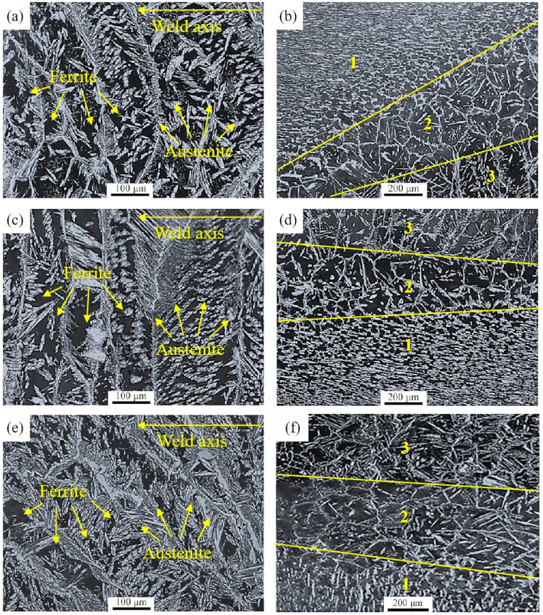
3.1. Microstructure
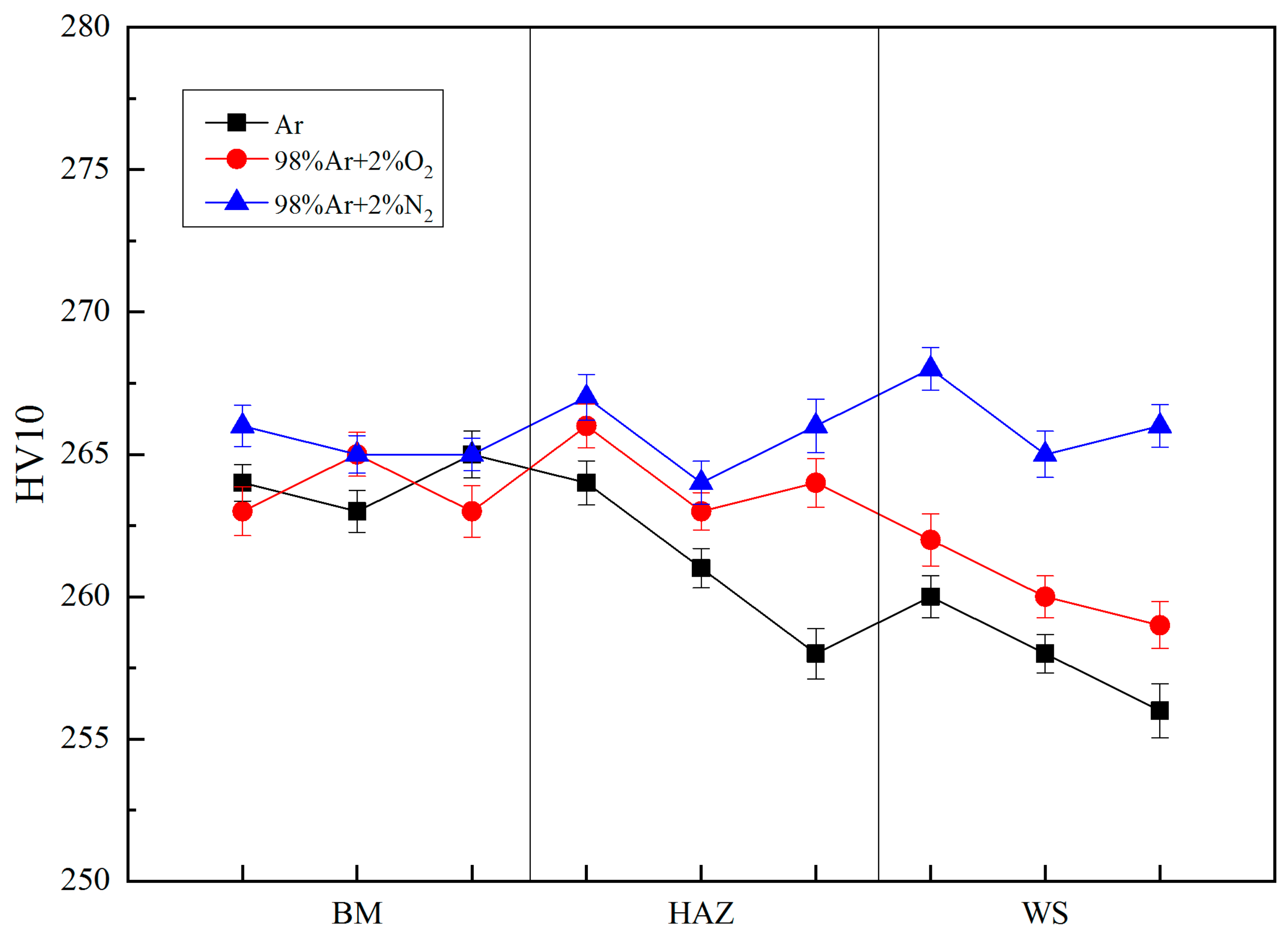
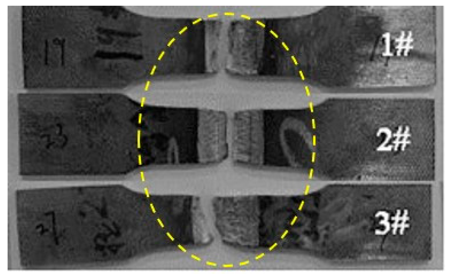
3.2. Mechanical Properties
3.3. Corrosion Resistance
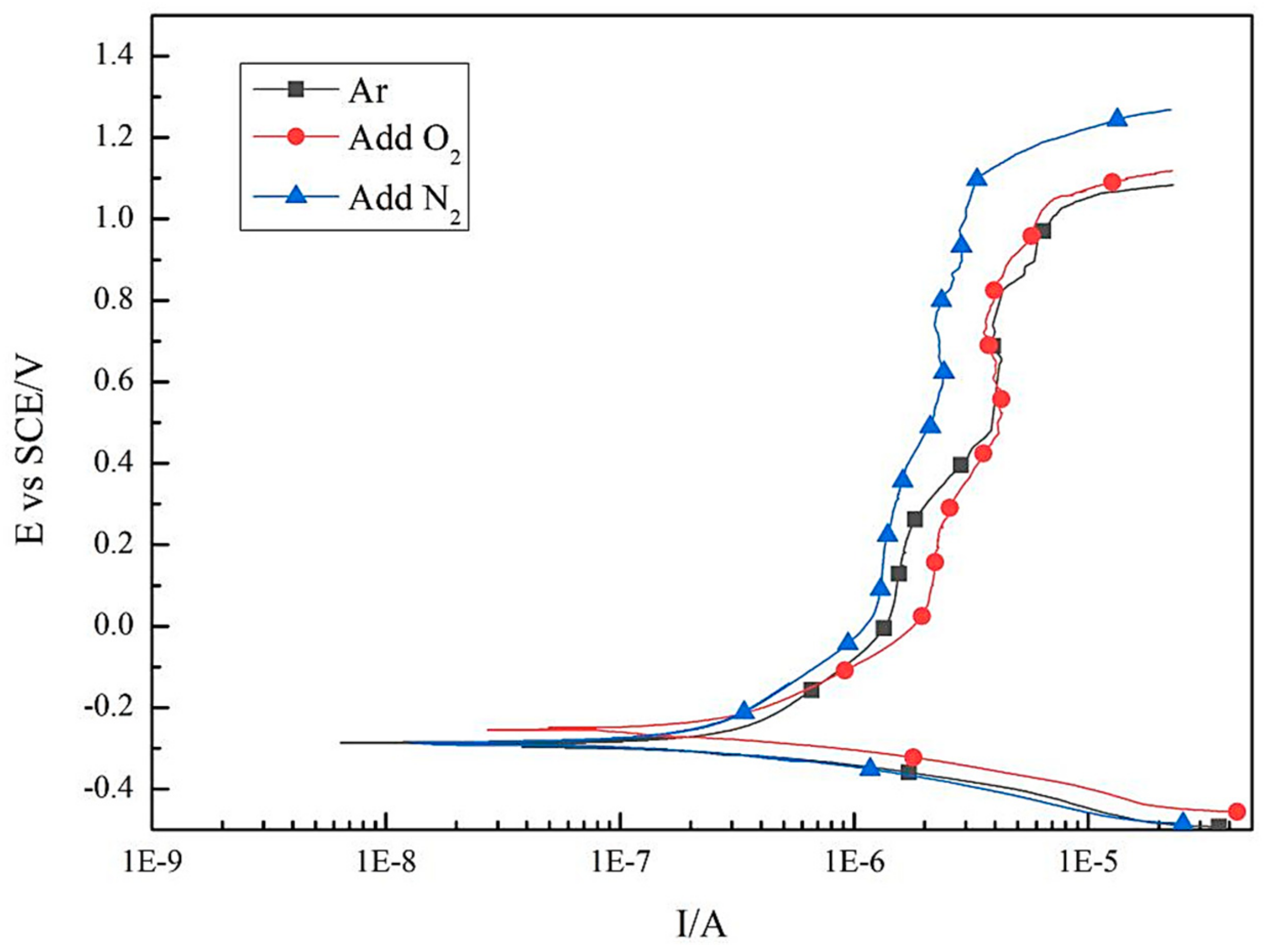
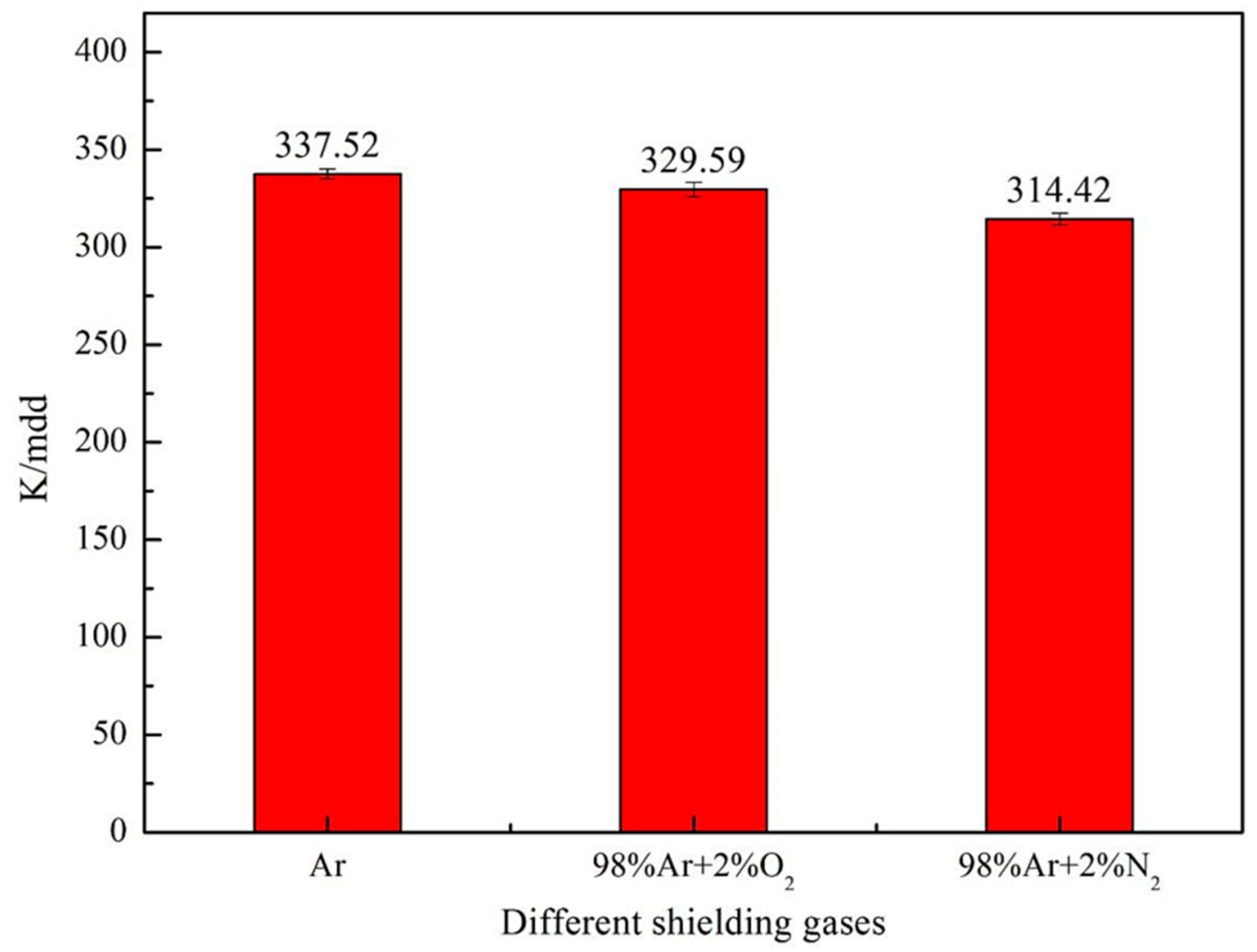
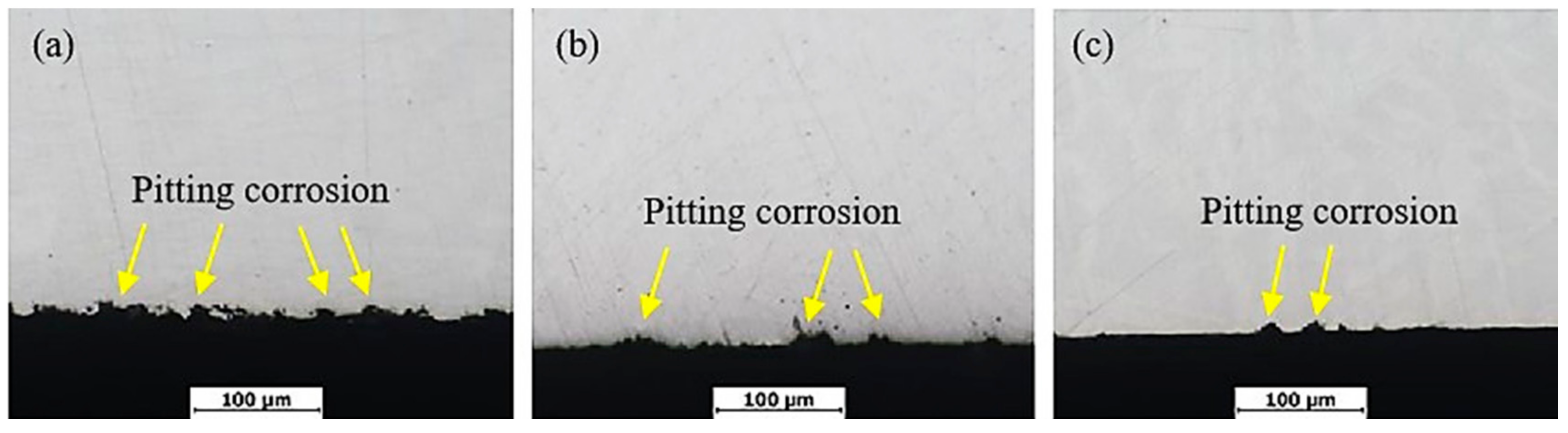
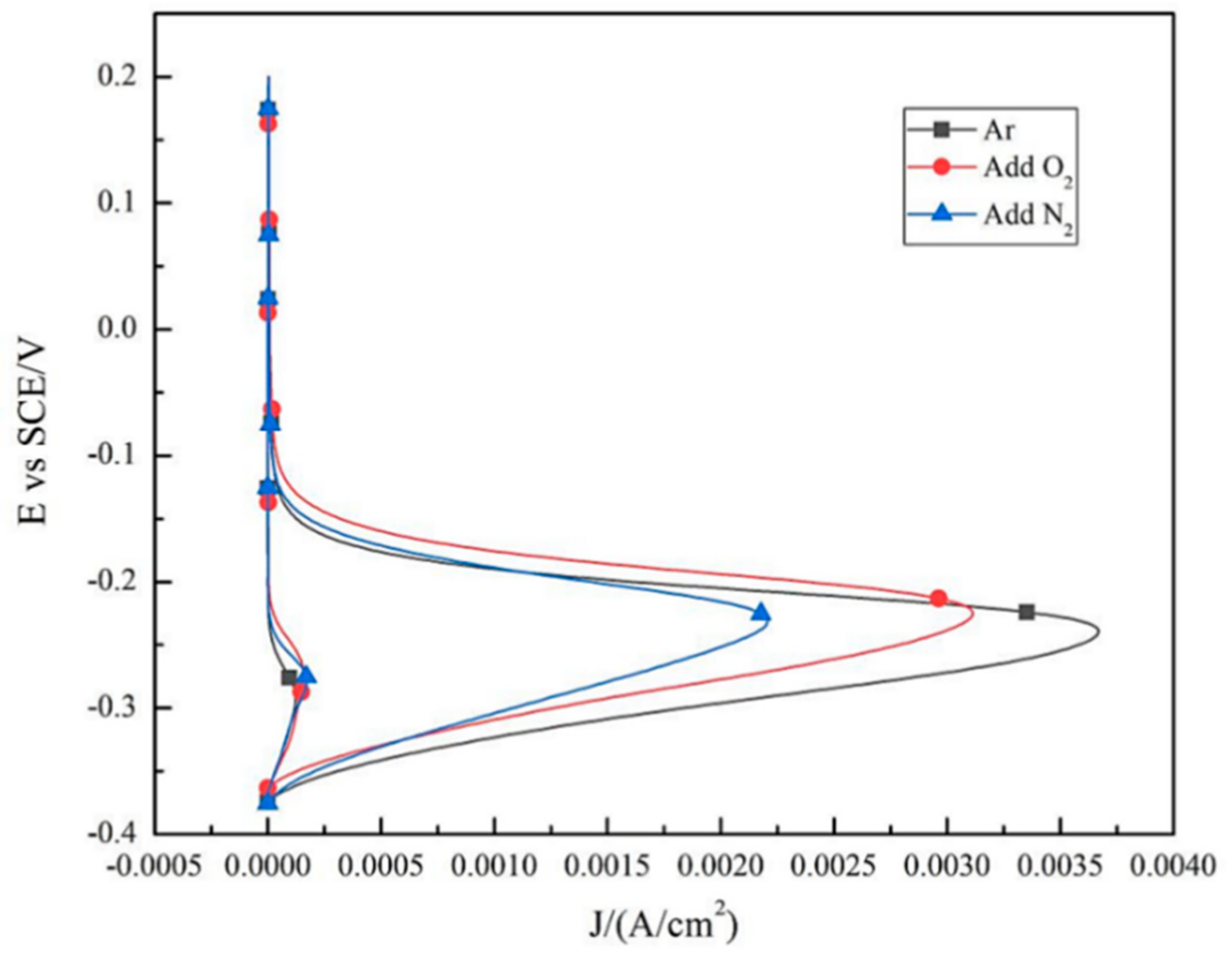
3.3.1. Pitting Corrosion
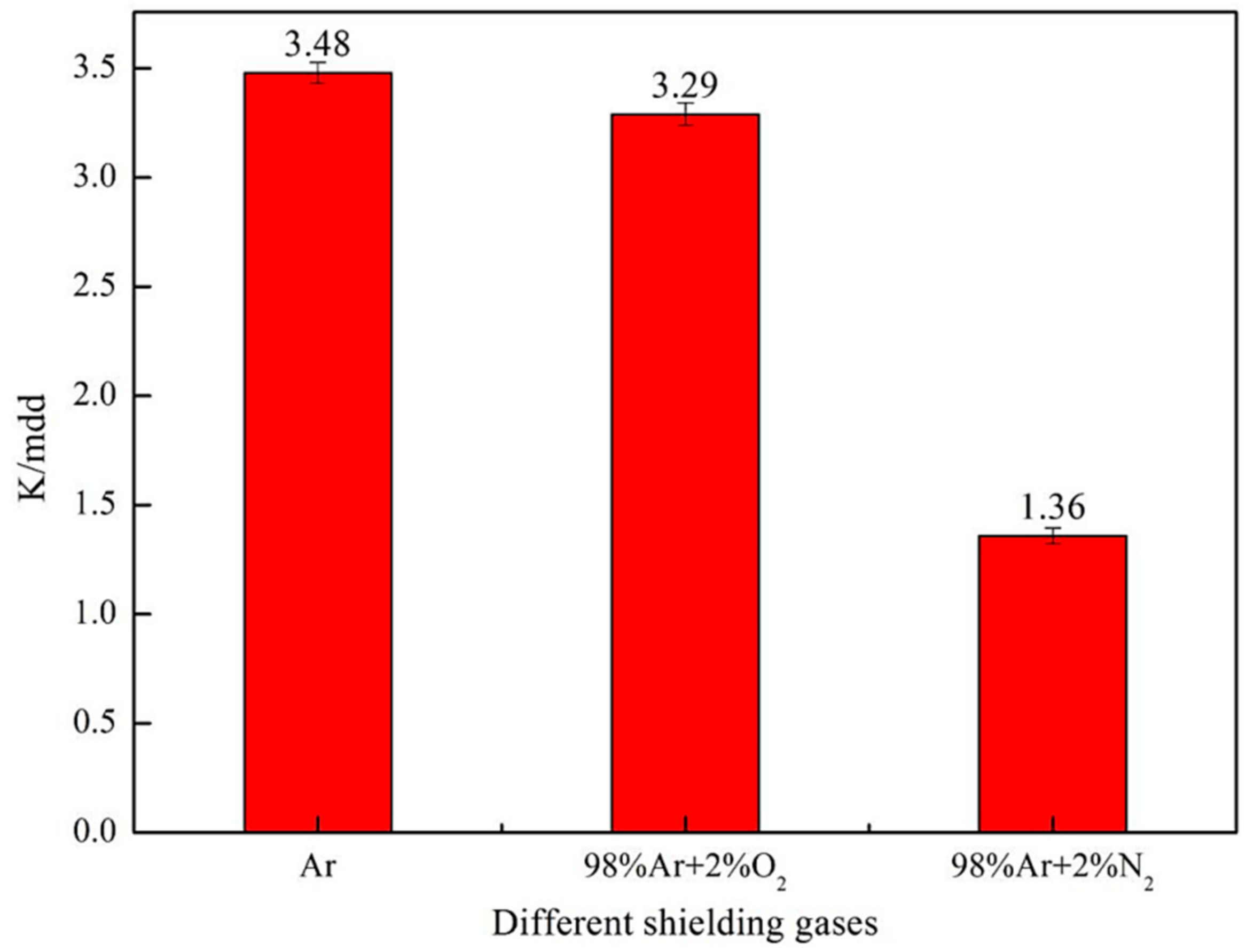
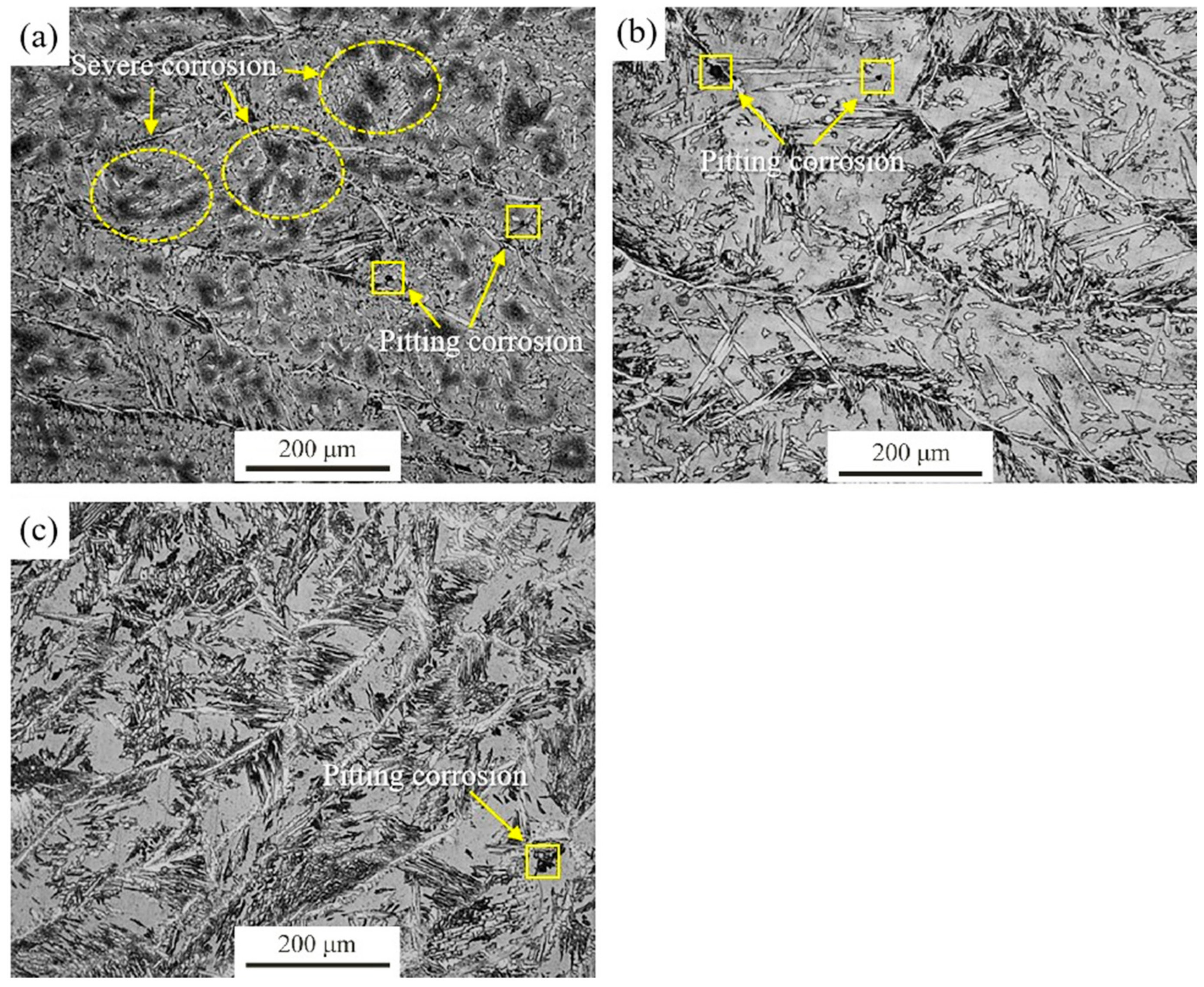
3.3.2. Intergranular Corrosion
4. Discussion
5. Conclusions
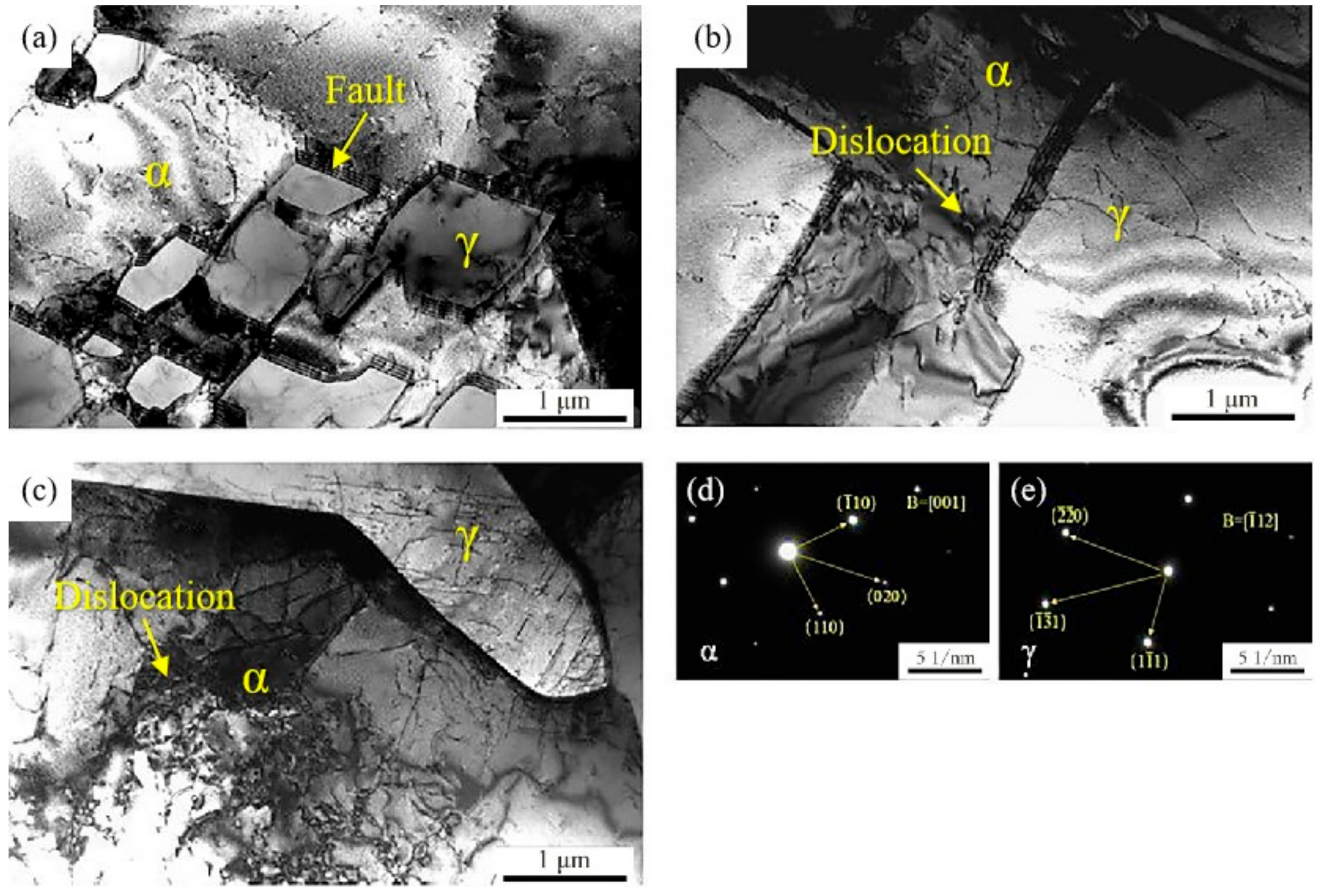
- When DSS 2205 solid core MIG welding is performed in 98%Ar + 2%O2 mixed atmosphere, the crystal defects (layering faults) are reduced, and the joint strength and corrosion resistance are improved, although the ferrite content of welded joints is similar to that of welded joints in pure Ar atmosphere.
- When DSS 2205 solid core MIG welding is performed in 98%Ar + 2%N2 mixed atmosphere, the austenite contents in WS and HAZ are both increased. The phase equilibrium and microstructure homogeneity are improved, and the strength and the corrosion resistance of the welded jointsare also enhanced.
- Compared with DSS 2205 solid core MIG welding in 98%Ar + 2%O2 mixed atmosphere, the strength and corrosion resistance of welded joints are improved more obviously in 98%Ar + 2%N2 mixed atmosphere.
Author Contributions
Funding
Institutional Review Board Statement
Informed Consent Statement
Data Availability Statement
Conflicts of Interest
References
- Chaudhari, A.N.; Dixit, K.; Bhatia, G.S.; Singh, B.; Singhal, P.; Saxena, K.K. Welding Behaviour of Duplex Stainless Steel AISI 2205: A Review. Mater. Today Proc. 2019, 18, 2731–2737. [Google Scholar] [CrossRef]
- Hou, Y.; Zhao, J.; Cheng, C.-Q.; Zhang, L.; Li, J.; Liu, B.-J.; Cao, T.-S. The metastable pitting corrosion of 2205 duplex stainless steel under bending deformation. J. Alloys Compd. 2020, 830, 154422. [Google Scholar] [CrossRef]
- Zhang, Z.; Zhang, H.; Zhao, H.; Li, J. Effect of prolonged thermal cycles on the pitting corrosion resistance of a newly developed LDX 2404 lean duplex stainless steel. Corros. Sci. 2016, 103, 189–195. [Google Scholar] [CrossRef]
- Kong, D.C.; Ni, X.; Dong, C.; Lei, X.; Zhang, L.; Man, C.; Yao, J.; Cheng, X.; Li, X. Bio-functional and anti-corrosive 3D printing 316L stainless steel fabricated by selective laser melting. Mater. Des. 2018, 152, 88–101. [Google Scholar] [CrossRef]
- Conradi, M.; Schon, P.M.; Kocijan, A.; Jenko, M.; Vancso, G.J. Surface analysis of localized corrosion of austenitic 316L and duplex 2205 stainless steels in simulated body solutions. Mater. Chem. Phys. 2011, 130, 708–713. [Google Scholar] [CrossRef]
- Jinlong, L.; Zhuqing, W.; Tongxiang, L.; Ken, S.; Hideo, M. Enhancing the corrosion resistance of the 2205 duplex stainless steel bipolar plates in PEMFCs environment by surface enriched molybdenum. Results Phys. 2017, 7, 3459–3464. [Google Scholar] [CrossRef]
- Li, S.; Dong, H.; Wang, X.; Liu, Z.; Tan, Z.; Shangguan, L.; Lu, Q.; Zhong, S. Effect of repair welding on microstructure and mechanical properties of 7N01 aluminum alloy MIG welded joint. J. Manuf. Process. 2020, 54, 80–88. [Google Scholar] [CrossRef]
- Lorenz, S.; Kannengiesser, T.; Posch, G. Solid Wire vs. Flux Cored Wire -Comparing Investigations for GMA-Laser-Hybrid Welding; Elsevier: Amsterdam, The Netherlands, 2008; pp. 477–484. [Google Scholar]
- Suban, M.; Tusek, J. Dependence of melting rate in MIG/MAG welding on the type of shielding gas used. J. Mater. Process. Technol. 2001, 119, 185–192. [Google Scholar] [CrossRef]
- Arturo, G.R.M.; Hugo, L.M.V.; Rafael, G.H.; Egberto, B.B.; Antonio, G.S.J. Electrochemical Characterization of AISI 2205 Duplex Stainless Steel Welded Joints with Electromagnetic Interaction. Procedia Mater. Sci. 2015, 8, 950–958. [Google Scholar] [CrossRef] [Green Version]
- Świerczyńska, A.; Łabanowski, J.; Michalska, J.; Fydrych, D. Corrosion behavior of hydrogen charged super duplex stainless steel welded joints. Mater. Corros. 2017, 68, 1037–1045. [Google Scholar] [CrossRef]
- Świerczyńska, A.; Fydrych, D.; Landowski, M.; Rogalski, G.; Łabanowski, J. Hydrogen embrittlement of X2CrNiMoCuN25-6-3 super duplex stainless steel welded joints under cathodic protection. Constr. Build. Mater. 2020, 238, 117697. [Google Scholar] [CrossRef]
- Gurcik, T.; Kovanda, K.; Rohan, P. Influence of Shielding Gas on Geometrical Quality ofWaam Technology. In Proceeding of the 28th International Conference on Metallurgy and Materials, Brno, Czech Republic, 22–24 May 2019. [Google Scholar]
- de Salazar, J.M.G.; Soria, A.; Barrena, M.I. The effect of N-2 addition upon the MIG welding process of duplex steels. J. Mater. Sci. 2007, 42, 4892–4898. [Google Scholar] [CrossRef]
- Tatagiba, L.C.S.; Goncalves, R.B.; Paranhos, R. Trends in the Development of Protective Gases Used in GMAW Welding. Soldag. Insp. 2012, 17, 218–228. [Google Scholar] [CrossRef] [Green Version]
- Nakamura, T.; Hiraoka, K.; Zenitani, S. Improvement of MIG welding stability in pure Ar shielding gas using small amount of oxygen and coaxial hybrid solid wire. Sci. Technol. Weld. Join. 2008, 13, 25–32. [Google Scholar] [CrossRef]
- Castillon, Q.; Wartel, M.; Pellerin, N.; Pellerin, S.; Faubert, F.; Planckaert, J.P.; Briand, F. Analysis of Gas Metal Arc Welding (GMAW) regime transition in Ar-CO2/O2 shielding gases. J. Phys. Conf. Ser. 2019. [Google Scholar] [CrossRef]
- Łabanowski, J.; Świerczyńska, A.; Topolska, S. Effect of Microstructure on Mechanical Properties and Corrosion Resistance of 2205 Duplex Stainless Steel. Pol. Marit. Res. 2015, 21, 108–112. [Google Scholar] [CrossRef] [Green Version]
- Stankiewicz, M.; Ślązek, B. Arc welding of duplex steinless steels considering maximum increase in weld corrosion resistance. Weld. Tech. Rev. 2017, 90, 5. [Google Scholar]
- Zha, X.; Xiong, Y.; Zhou, T.; Ren, Y.; Hei, P.; Zhai, Z.; Kömi, J.; Huttula, M.; Cao, W. Impacts of Stress Relief Treatments on Microstructure, Mechanical and Corrosion Properties of Metal Active-Gas Welding Joint of 2205 Duplex Stainless Steel. Materials 2020, 13, 4272. [Google Scholar] [CrossRef]
- Zhang, W.; DebRoy, T.; Palmer, T.A.; Elmer, J.W. Modeling of ferrite formation in a duplex stainless steel weld considering non-uniform starting microstructure. Acta Mater. 2005, 53, 4441–4453. [Google Scholar] [CrossRef]
- Hertzman, S.; Ferreira, P.J.; Brolund, B. An experimental and theoretical study of heat-affected zone austenite reformation in three duplex stainless steels. Met. Mater. Trans. 1997, 28, 277–285. [Google Scholar] [CrossRef]
- Dai, W.; Yang, T.; Zhou, Z.M.; Huang, Z.; Chen, H. Effect of helium-argon shielding gas in laser-metal inert-gas hybrid welded-brazed Al/steel dissimilar joint. J. Laser Appl. 2019. [Google Scholar] [CrossRef]
- Nakamura, T.; Hiraoka, K.; Takahashi, M.; Sasaki, T. Gas metal arc welding process with periodic control of shielding gas composition. Sci. Technol. Weld. Join. 2005, 10, 131–138. [Google Scholar] [CrossRef]
- Galdino, L.G.; Rodrigues, S.F.; Aranas, C.; Reis, G.S.; Ferraresi, V.A. The effect of purge gas condition on the amount of ferrite in tubular AISI 304 stainless steel during welding. J. Braz. Soc. Mech. Sci. 2018, 40, 376. [Google Scholar] [CrossRef]
- Rokanopoulou, A.; Skarvelis, P.; Papadimitriou, G.D. Welding design methodology for optimization of phase balance in duplex stainless steels during autogenous arc welding under Ar-N-2 atmosphere. Weld. World 2019, 63, 3–10. [Google Scholar] [CrossRef]
- Varbai, B.; Adonyi, Y.; Baumer, R.; Pickle, T. Weldability of Duplex Stainless Steels-Thermal Cycle and Nitrogen Effects. Weld. J. 2018, 98, 78–87. [Google Scholar]
- Varbai, B.; Pickle, T.; Májlinger, K. Effect of heat input and role of nitrogen on the phase evolution of 2205 duplex stainless steel weldment. Int. J. Press. Vessel. Pip. 2019, 176, 103952. [Google Scholar] [CrossRef]
- Petrov, Y.N.; Gavriljuk, V.G.; Berns, H.; Escher, C. Nitrogen partitioning between matrix, grain boundaries and precipitates in high-alloyed austenitic steels. Scr. Mater. 1999, 40, 669–674. [Google Scholar] [CrossRef]
- Cui, B.; Zhang, H.; Liu, F.D. Effects of shielding gas composition on the welding stability, microstructure and mechanical properties in laser-arc hybrid welding of high nitrogen steel. Mater. Res. Express 2018. [Google Scholar] [CrossRef]
- Milani, J.M.; Saeid, T. Acicular ferrite nucleation and growth in API5L-X65 steel submerged arc welded joints. Mater. Sci. Technol. 2020, 36, 1398–1406. [Google Scholar] [CrossRef]
- Nunez, E.E.N.; Silgado, J.U.; Salcedo, J.E.; Ramirez, A.J. Influence of Gas Mixtures Ar-He and Ar-He-O-2 on weldability of aluminum alloy AA5083-O using Automated GMAW-P. Soldag. Insp. 2014, 19, 238–246. [Google Scholar] [CrossRef] [Green Version]
- Cevik, B. Theeffect of pure argon and mixed gases on microstructural and mechanical properties of S275 structural steel joined by flux-cored arc welding. Kov. Mater. 2018, 56, 81–87. [Google Scholar]
- Cai, D.; Luo, Z.; Han, L.; Han, S.; Yi, Y. Porosity and joint property of laser-MIG hybrid welding joints for 304 stainless steel. J. Laser Appl. 2020. [Google Scholar] [CrossRef]
- Zhang, Z.; Jing, H.; Xu, L.; Han, Y.; Zhao, L.; Zhang, J. Influence of microstructure and elemental partitioning on pitting corrosion resistance of duplex stainless steel welding joints. Appl. Surf. Sci. 2017, 394, 297–314. [Google Scholar] [CrossRef]
- Zhang, Y.; Cheng, S.; Wu, S.; Cheng, F. The evolution of microstructure and intergranular corrosion resistance of duplex stainless steel joint in multi-pass welding. J. Mater. Process. Technol. 2020, 277, 116471. [Google Scholar] [CrossRef]
- Lin, P.; Palumbo, G.; Erb, U. Influence of grain boundary character distribution on sensitization and intergranular corrosion of alloy. Scr. Metall. Mater. 1995, 33, 1387–1392. [Google Scholar] [CrossRef]


| Material | C | Si | Mn | Cr | Ni | Mo | N | Fe |
|---|---|---|---|---|---|---|---|---|
| DSS2205 | 0.025 | 0.60 | 1.50 | 22.50 | 5.70 | 3.00 | 0.15 | Balance |
| ER2209 | 0.017 | 0.57 | 1.61 | 22.06 | 8.84 | 2.68 | 0.11 | Balance |
| Samples | No.1 | No.2 | No.3 |
|---|---|---|---|
| Ferrite content in WS (%) | 58.54 | 57.18 | 51.35 |
| Ferrite content in HAZ (%) | 65.17 | 64.58 | 59.24 |
| Samples | No.1 | No.2 | No.3 |
|---|---|---|---|
| Tensile strength (MPa) | 803 | 812 | 823 |
| Samples | Corrosion Potential ECorr (mV) | Pitting Potential Ep (mV) | Potential Difference ΔE (mV) |
|---|---|---|---|
| No.1 | −286 | 1025 | 1311 |
| No.2 | −255 | 1050 | 1305 |
| No.3 | −291 | 1103 | 1394 |
Publisher’s Note: MDPI stays neutral with regard to jurisdictional claims in published maps and institutional affiliations. |
© 2021 by the authors. Licensee MDPI, Basel, Switzerland. This article is an open access article distributed under the terms and conditions of the Creative Commons Attribution (CC BY) license (https://creativecommons.org/licenses/by/4.0/).
Share and Cite
Zhang, X.-Y.; Zha, X.-Q.; Gao, L.-Q.; Hei, P.-H.; Ren, Y.-F. Influence of Shielding Gas on Microstructure and Properties of GMAW DSS2205 Welded Joints. Materials 2021, 14, 2671. https://doi.org/10.3390/ma14102671
Zhang X-Y, Zha X-Q, Gao L-Q, Hei P-H, Ren Y-F. Influence of Shielding Gas on Microstructure and Properties of GMAW DSS2205 Welded Joints. Materials. 2021; 14(10):2671. https://doi.org/10.3390/ma14102671
Chicago/Turabian StyleZhang, Xin-Yu, Xiao-Qin Zha, Ling-Qing Gao, Peng-Hui Hei, and Yong-Feng Ren. 2021. "Influence of Shielding Gas on Microstructure and Properties of GMAW DSS2205 Welded Joints" Materials 14, no. 10: 2671. https://doi.org/10.3390/ma14102671