Ligno-Cellulosic Fibre Sized with Nucleating Agents Promoting Transcrystallinity in Isotactic Polypropylene Composites


Abstract
:1. Introduction
2. Materials and Methods
2.1. Materials
2.1.1. Fibres
2.1.2. Nucleating Agents
2.1.3. Polypropylene and Compatibiliser
2.2. Methods
2.2.1. Sizing of the Fibre and Fibre Pellet Production
2.2.2. Nitrogen Analysis
2.2.3. Compounding
2.2.4. Injection Moulding
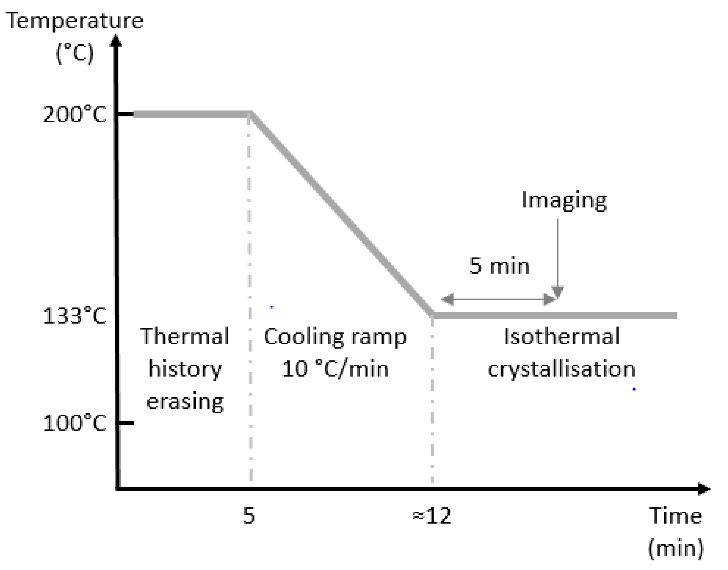
2.2.5. Polarised Light Optical Microscopy (PLOM)
2.2.6. Etching
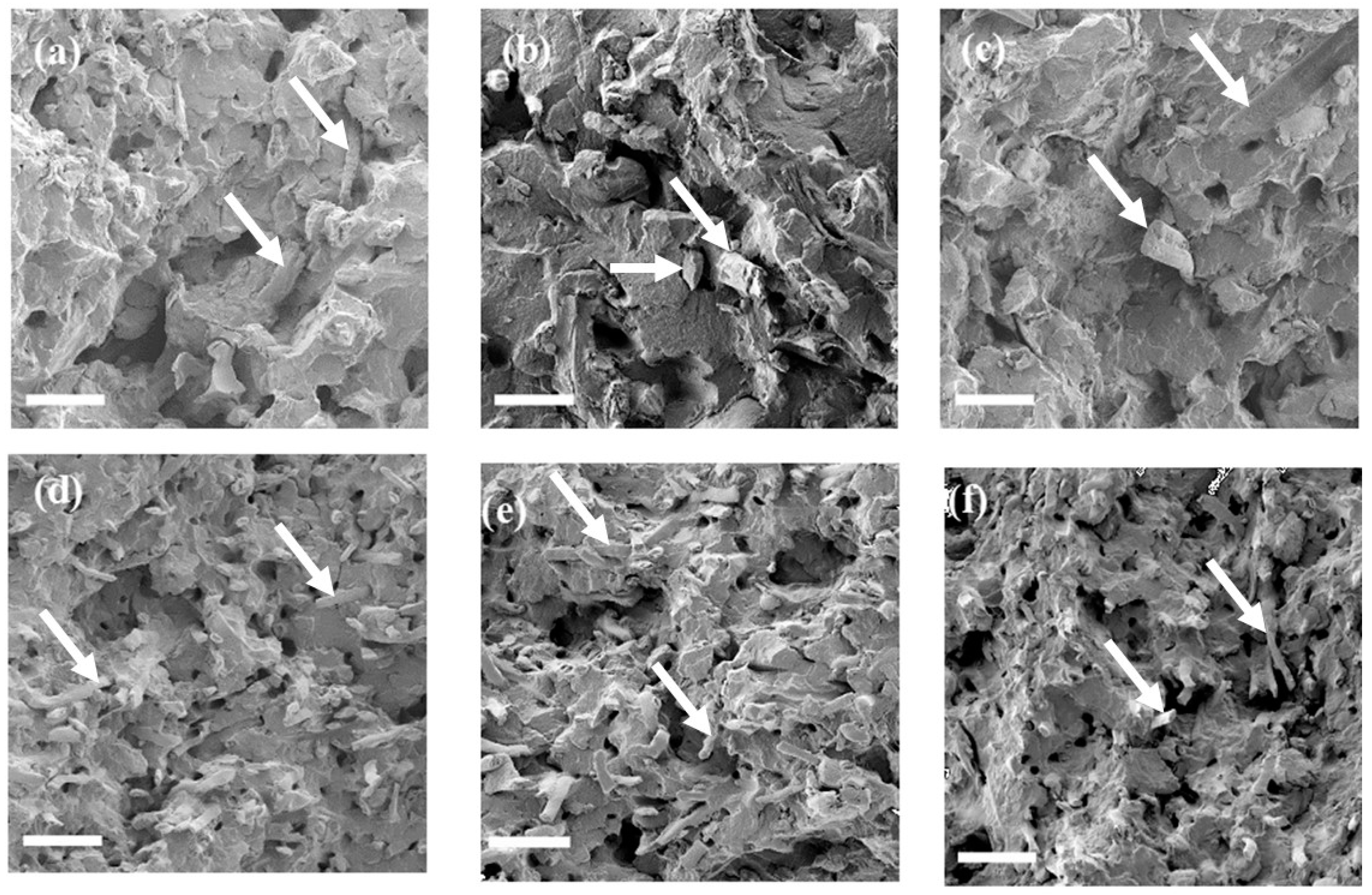
2.2.7. Scanning Electron Microscopy (SEM)
2.2.8. Crystal Size Measurement
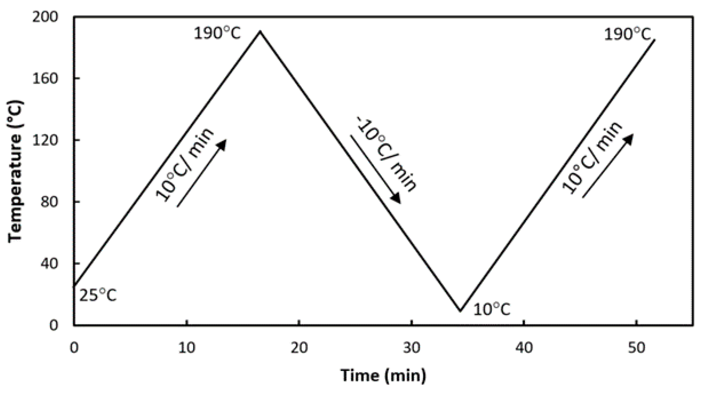
2.2.9. Differential Scanning Calorimetry (DSC)
2.2.10. Mechanical Testing
Tensile and Modulus Tests
Impact Test
2.2.11. Water Uptake
3. Results
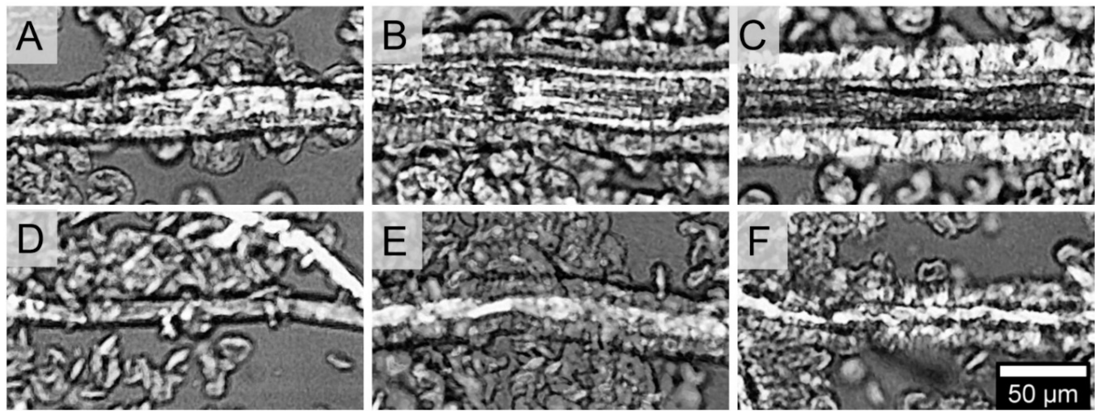
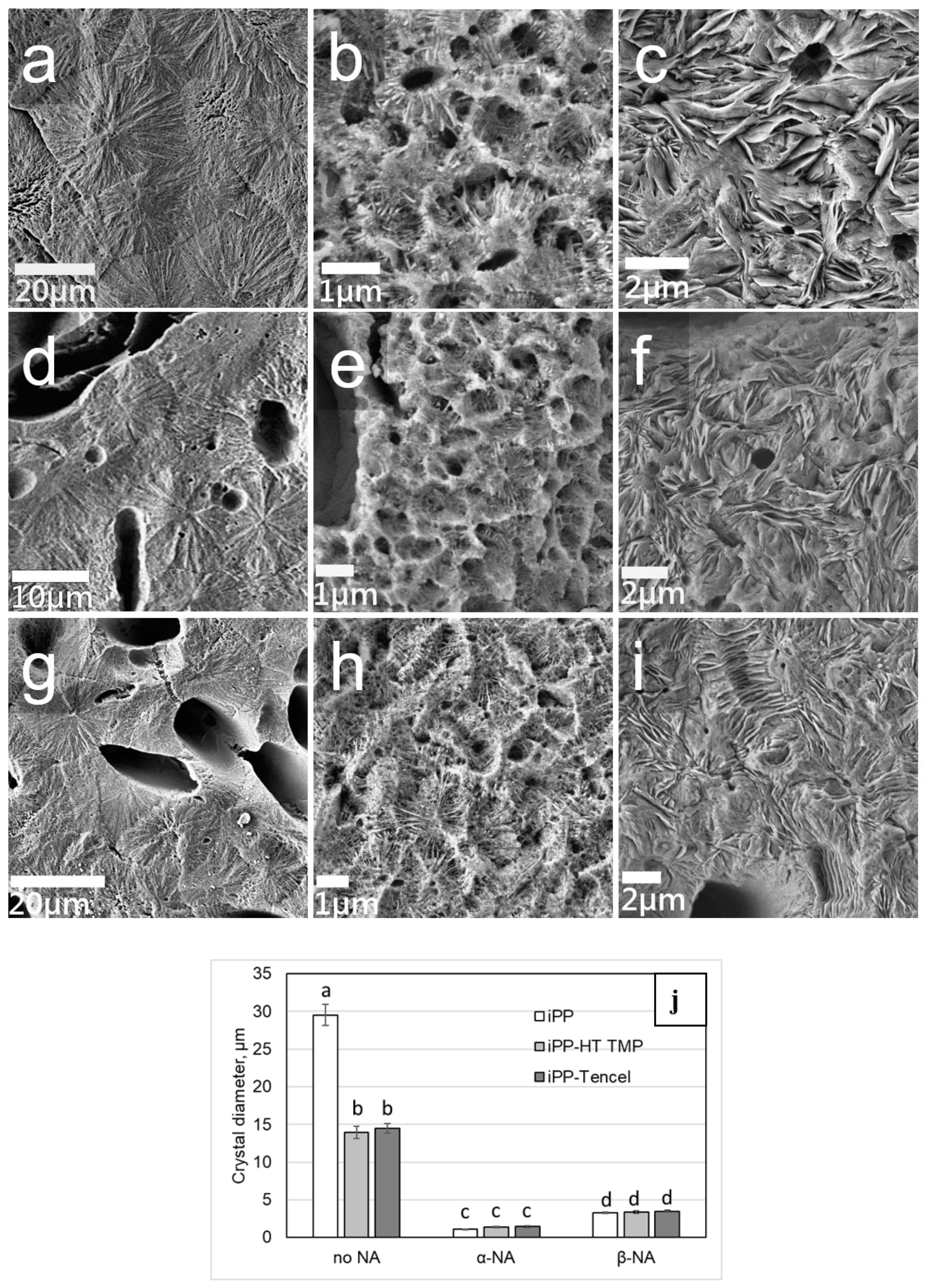
3.1. Crystal Structure
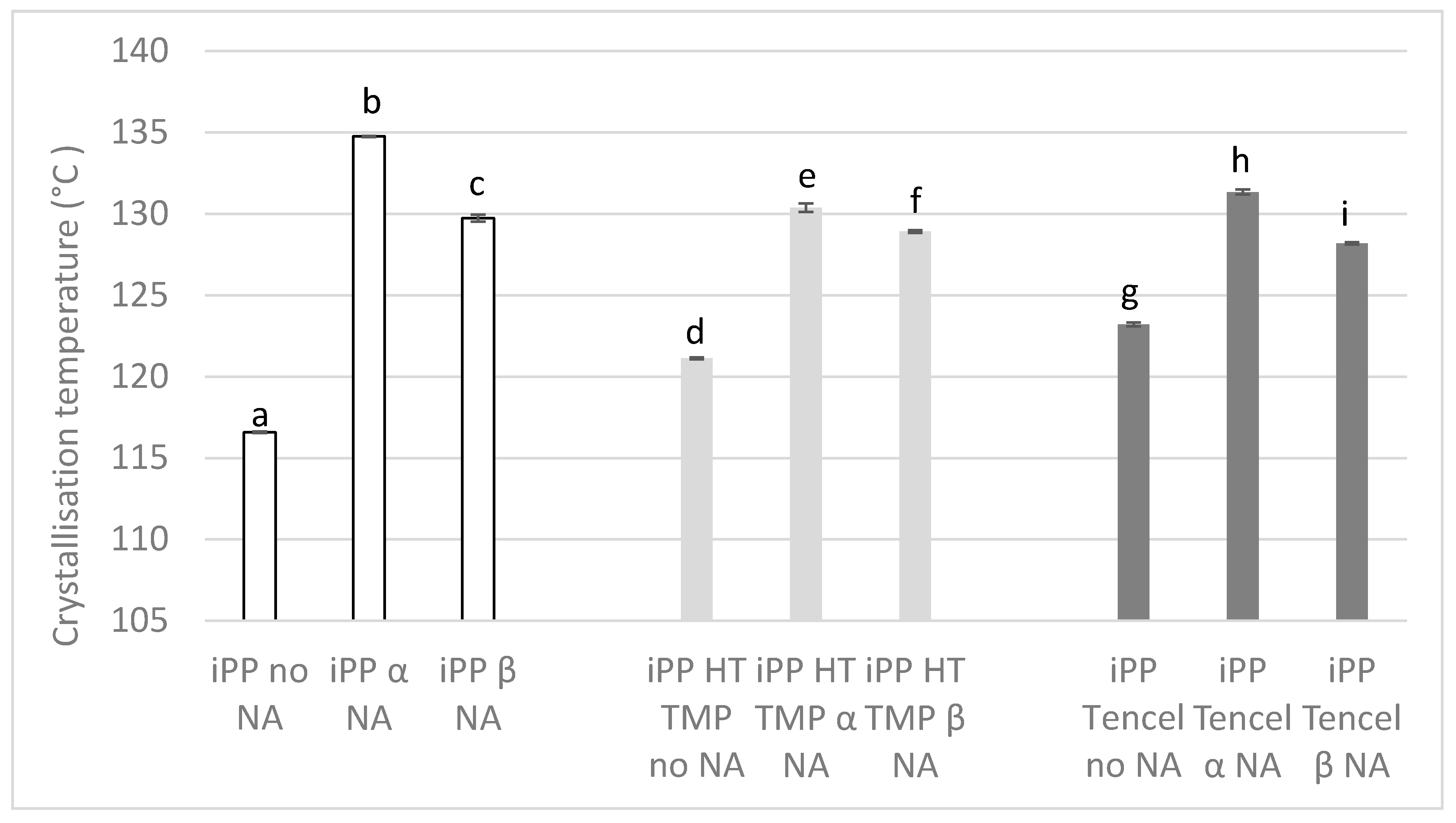
3.2. Differential Scanning Calorimetry (DSC)
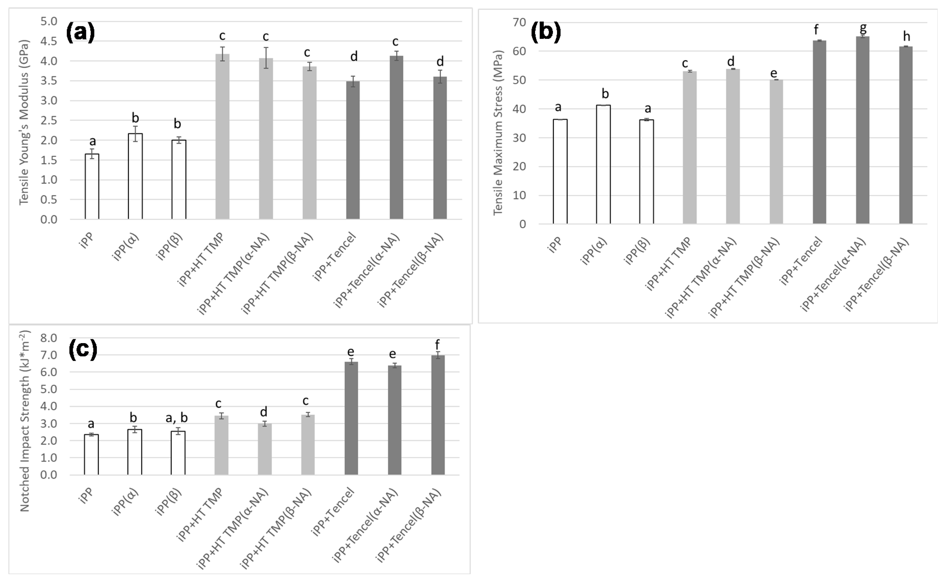
3.3. Mechanical Properties
3.3.1. Young’s Modulus and Stress
3.3.2. Impact Strength
3.4. Pull Out
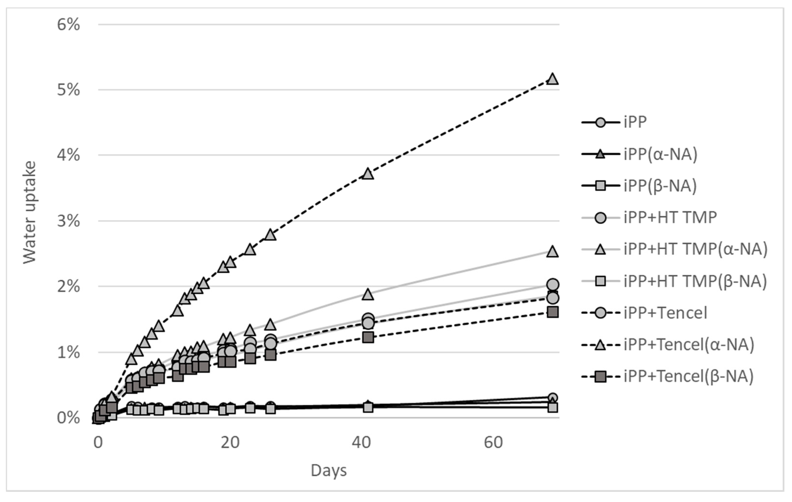
3.5. Water Uptake
4. Discussion
5. Conclusions
- The α- and β-NA as fibre sizings have the expected effect on iPP crystals.
- The α- and β-NA cause transcrystallinity at the interphase fibre-matrix in a sandwich composite.
- The α- and β-NA affects the whole matrix crystallinity after compounding.
- The tensile strength and impact strength of the fibre-iPP composite is not significantly improved by the NA.
Author Contributions
Funding
Acknowledgments
Conflicts of Interest
References
- Clements, A.; Dunn, M.; Firth, V.; Hubbard, L.; Laonby, J.; Waddington, D. The essential chemical industry. Chem. Ind. Educ. Cent. Univ. York. UK 2010, 511, 34. [Google Scholar]
- Zhang, L.; Qin, Y.; Zheng, G.; Dai, K.; Liu, C.; Yan, X.; Guo, J.; Shen, C.; Guo, Z. Interfacial crystallization and mechanical property of isotactic polypropylene based single-polymer composites. Polymer 2016, 90, 18–25. [Google Scholar] [CrossRef]
- Li, M.; Li, G.; Zhang, Z.; Dai, X.; Mai, K. Enhanced β-crystallization in polypropylene random copolymer with a supported β-nucleating agent. Thermochim. Acta 2014, 598, 36–44. [Google Scholar] [CrossRef]
- Kersch, M.; Schmidt, H.-W.; Altstädt, V. Influence of different beta-nucleating agents on the morphology of isotactic polypropylene and their toughening effectiveness. Polymer 2016, 98, 320–326. [Google Scholar] [CrossRef]
- Zhang, Y.; Zhang, L.; Liu, H.; Du, H.; Zhang, J.; Wang, T.; Zhang, X. Novel approach to tune mechanics of β-nucleation agent nucleated polypropylene: Role of oriented β spherulite. Polymer 2013, 54, 6026–6035. [Google Scholar] [CrossRef]
- Silvestre, C.; Cimmino, S.; Duraccio, D.; Schick, C. Isothermal crystallization of isotactic poly (propylene) studied by superfast calorimetry. Macromol. Rapid Commun. 2007, 28, 875–881. [Google Scholar] [CrossRef]
- De Santis, F.; Adamovsky, S.; Titomanlio, G.; Schick, C. Isothermal nanocalorimetry of isotactic polypropylene. Macromolecules 2007, 40, 9026–9031. [Google Scholar] [CrossRef]
- Grein, C. Toughness of neat, rubber modified and filled β-nucleated polypropylene: From fundamentals to applications. In Intrinsic Molecular Mobility and Toughness of Polymers ii; Springer: Berlin/Heidelberg, Germany, 2005; pp. 43–104. [Google Scholar]
- Cai, Z.; Zhang, Y.; Li, J.; Xue, F.; Shang, Y.; He, X.; Feng, J.; Wu, Z.; Jiang, S. Real time synchrotron saxs and waxs investigations on temperature related deformation and transitions of β-iPP with uniaxial stretching. Polymer 2012, 53, 1593–1601. [Google Scholar] [CrossRef]
- Chen, Y.; Wu, Z.; Fan, Q.; Yang, S.; Song, E.; Zhang, Q. Great toughness reinforcement of isotactic polypropylene/elastomer blends with quasi-cocontinuous phase morphology by traces of β-nucleating agents and carbon nanotubes. Compos. Sci. Technol. 2018, 167, 277–284. [Google Scholar] [CrossRef]
- Shangguan, Y.; Song, Y.; Peng, M.; Li, B.; Zheng, Q. Formation of β-crystal from nonisothermal crystallization of compression-molded isotactic polypropylene melt. Eur. Polym. J. 2005, 41, 1766–1771. [Google Scholar] [CrossRef]
- Zhang, B.; Chen, J.; Ji, F.; Zhang, X.; Zheng, G.; Shen, C. Effects of melt structure on shear-induced β-cylindrites of isotactic polypropylene. Polymer 2012, 53, 1791–1800. [Google Scholar] [CrossRef]
- Sun, X.; Li, H.; Zhang, X.; Wang, J.; Wang, D.; Yan, S. Effect of fiber molecular weight on the interfacial morphology of iPP fiber/matrix single polymer composites. Macromolecules 2006, 39, 1087–1092. [Google Scholar] [CrossRef]
- Wang, L.; Yang, M.-B. Unusual hierarchical distribution of β-crystals and improved mechanical properties of injection-molded bars of isotactic polypropylene. Rsc Adv. 2014, 4, 25135–25147. [Google Scholar] [CrossRef]
- Kang, J.; Wang, B.; Peng, H.; Li, J.; Chen, J.; Gai, J.; Cao, Y.; Li, H.; Yang, F.; Xiang, M. Investigation on the dynamic crystallization and melting behavior of β-nucleated isotactic polypropylene with different stereo-defect distribution—The role of dual-selective β-nucleation agent. Polym. Adv. Technol. 2014, 25, 97–107. [Google Scholar] [CrossRef]
- Assouline, E.; Pohl, S.; Fulchiron, R.; Gerard, J.-F.; Lustiger, A.; Wagner, H.; Marom, G. The kinetics of α and β transcrystallization in fibre-reinforced polypropylene. Polymer 2000, 41, 7843–7854. [Google Scholar] [CrossRef]
- Sanadi, A.; Young, R.; Clemons, C.; Rowell, R. Recycled newspaper fibers as reinforcing fillers in thermoplastics: Part i-analysis of tensile and impact properties in polypropylene. J. Reinf. Plast. Compos. 1994, 13, 54–67. [Google Scholar] [CrossRef]
- Thomason, J. The influence of fibre length and concentration on the properties of glass fibre reinforced polypropylene: 5. Injection moulded long and short fibre PP. Compos. Part A Appl. Sci. Manuf. 2002, 33, 1641–1652. [Google Scholar] [CrossRef]
- Hyer, M.W. Stress Analysis of Fiber-Reinforced Composite Materials; DEStech Publications, Inc.: Lancaster, PA, USA, 2009. [Google Scholar]
- Bourmaud, A.; Ausias, G.; Lebrun, G.; Tachon, M.L.; Baley, C. Observation of the structure of a composite polypropylene/flax and damage mechanisms under stress. Ind. Crop. Prod. 2013, 43, 225–236. [Google Scholar] [CrossRef]
- Thomason, J.; Van Rooyen, A. Transcrystallized interphase in thermoplastic composites. J. Mater. Sci. 1992, 27, 897–907. [Google Scholar] [CrossRef]
- Quan, H.; Li, Z.-M.; Yang, M.-B.; Huang, R. On transcrystallinity in semi-crystalline polymer composites. Compos. Sci. Technol. 2005, 65, 999–1021. [Google Scholar] [CrossRef]
- Yan, B.; Wu, H.; Jiang, G.; Guo, S.; Huang, J. Interfacial crystalline structures in injection over-molded polypropylene and bond strength. Acs Appl. Mater. Interfaces 2010, 2, 3023–3036. [Google Scholar] [CrossRef] [PubMed]
- Xu, H.; Xie, L.; Jiang, X.; Li, X.-J.; Li, Y.; Zhang, Z.-J.; Zhong, G.-J.; Li, Z.-M. Toward stronger transcrystalline layers in poly(l-lactic acid)/natural fiber biocomposites with the aid of an accelerator of chain mobility. J. Phys. Chem. B 2014, 118, 812–823. [Google Scholar] [CrossRef] [PubMed]
- Garkhail, S.; Wieland, B.; George, J.; Soykeabkaew, N.; Peijs, T. Transcrystallisation in PP/flax composites and its effect on interfacial and mechanical properties. J. Mater. Sci. 2009, 44, 510–519. [Google Scholar] [CrossRef]
- Borysiak, S. Fundamental studies on lignocellulose/polypropylene composites: Effects of wood treatment on the transcrystalline morphology and mechanical properties. J. Appl. Polym. Sci. 2013, 127, 1309–1322. [Google Scholar] [CrossRef]
- Wang, C.; Liu, F.-H.; Huang, W.-H. Electrospun-fiber induced transcrystallization of isotactic polypropylene matrix. Polymer 2011, 52, 1326–1336. [Google Scholar] [CrossRef]
- Ning, N.; Zhang, W.; Yan, J.; Xu, F.; Wang, T.; Su, H.; Tang, C.; Fu, Q. Largely enhanced crystallization of semi-crystalline polymer on the surface of glass fiber by using graphene oxide as a modifier. Polymer 2013, 54, 303–309. [Google Scholar] [CrossRef]
- Wang, Y.; Tong, B.; Hou, S.; Li, M.; Shen, C. Transcrystallization behavior at the poly (lactic acid)/sisal fibre biocomposite interface. Compos. Part A: Appl. Sci. Manuf. 2011, 42, 66–74. [Google Scholar] [CrossRef]
- Sorieul, M.; Dickson, A.; Hill, S.J.; Pearson, H. Plant fibre: Molecular structure and biomechanical properties, of a complex living material, influencing its deconstruction towards a biobased composite. Materials 2016, 9, 618. [Google Scholar] [CrossRef]
- Markiewicz, E.; Borysiak, S.; Paukszata, D. Polypropylene-lignocellulosic material composites as promising sound absorbing materials. Polimery 2009, 54, 430–435. [Google Scholar] [CrossRef] [Green Version]
- Saheb, D.N.; Jog, J.P. Natural fiber polymer composites: A review. Adv. Polym. Technol. J. Polym. Process. Inst. 1999, 18, 351–363. [Google Scholar] [CrossRef]
- Karimi, K.; Taherzadeh, M.J. A critical review of analytical methods in pretreatment of lignocelluloses: Composition, imaging, and crystallinity. Bioresour. Technol. 2016, 200, 1008–1018. [Google Scholar] [CrossRef] [PubMed] [Green Version]
- Donaldson, L.; Lomax, T.D. Adhesive/fibre interaction in medium density fibreboard. Wood Sci. Technol. 1989, 23, 371–380. [Google Scholar] [CrossRef]
- Shao, Z.; Li, K. The effect of fiber surface lignin on interfiber bonding. J. Wood Chem. Technol. 2006, 26, 231–244. [Google Scholar] [CrossRef]
- Warnes, J.M.; Fernyhough, A.; Anderson, C.R.; Lee, B.J.; Witt, M.R.J. Method for Producing Wood Fibre Pellets. U.S. Patent 9,511,508, 6 December 2016. [Google Scholar]
- Thumm, A.; Even, D.; Gini, P.-Y.; Sorieul, M. Processing and properties of mdf fibre-reinforced biopolyesters with chain extender additives. Int. J. Polym. Sci. 2018, 2018, 9601753. [Google Scholar] [CrossRef]
- Bourban, C.; Karamuk, E.; De Fondaumiere, M.; Ruffieux, K.; Mayer, J.; Wintermantel, E. Processing and characterization of a new biodegradable composite made of a phb/v matrix and regenerated cellulosic fibers. J. Environ. Polym. Degrad. 1997, 5, 159–166. [Google Scholar]
- Graupner, N.; Müssig, J. A comparison of the mechanical characteristics of kenaf and lyocell fibre reinforced poly (lactic acid)(pla) and poly (3-hydroxybutyrate)(phb) composites. Compos. Part A Appl. Sci. Manuf. 2011, 42, 2010–2019. [Google Scholar] [CrossRef]
- McDonald, A.; Clare, A.; Dawson, B. Surface characterisation of radiata pine high-temperature TMP fibres by x-ray photo-electron spectroscopy. In Proceedings of the 53rd General APPITA Conference, Rotorua, New Zealand, 19–23 April 1999; pp. 51–57. [Google Scholar]
- Dickson, A.; Teuber, L.; Gaugler, M.; Sandquist, D. Effect of processing conditions on wood and glass fiber length attrition during twin screw composite compounding. J. Appl. Polym. Sci. 2020, 137, 48551. [Google Scholar] [CrossRef]
- Wolters, W.S.; Hanssen, R.; Palanisami, T.K.; Dotson, D.L. Nucleating Agent Additive Compositions and Methods. U.S. Patent 7,659,336, 9 February 2010. [Google Scholar]
- Ye, J.; Fang, J.; Zhang, L.; Li, C. Transcrystalline induced by mwcnts and organic nucleating agents at the interface of glass fiber/polypropylene. Polym. Compos. 2018, 39, 3424–3433. [Google Scholar] [CrossRef]
- Bassett, D.C.; Olley, R.H. On the lamellar morphology of isotactic polypropylene spherulites. Polymer 1984, 25, 935–943. [Google Scholar] [CrossRef]
- Schindelin, J.; Arganda-Carreras, I.; Frise, E.; Kaynig, V.; Longair, M.; Pietzsch, T.; Preibisch, S.; Rueden, C.; Saalfeld, S.; Schmid, B.; et al. Fiji: An open-source platform for biological-image analysis. Nat. Methods 2012, 9, 676. [Google Scholar] [CrossRef] [Green Version]
- Blaine, R.L. Thermal applications note. Polym. Heats Fusion, 2002. [Google Scholar]
- Ljungberg, N.; Cavaillé, J.-Y.; Heux, L. Nanocomposites of isotactic polypropylene reinforced with rod-like cellulose whiskers. Polymer 2006, 47, 6285–6292. [Google Scholar] [CrossRef]
- Habibi, Y.; Dufresne, A. Highly filled bionanocomposites from functionalized polysaccharide nanocrystals. Biomacromolecules 2008, 9, 1974–1980. [Google Scholar] [CrossRef] [PubMed]
- Gray, D.G. Transcrystallization of polypropylene at cellulose nanocrystal surfaces. Cellulose 2008, 15, 297–301. [Google Scholar] [CrossRef]
- Nwabunma, D.; Kyu, T. Polyolefin Composites; John Wiley & Sons: Hoboken, NJ, USA, 2008. [Google Scholar]
- Gray, D.G. Polypropylene transcrystallization at the surface of cellulose fibers. J. Polym. Sci. Polym. Lett. Ed. 1974, 12, 509–515. [Google Scholar] [CrossRef]
- Klapiszewski, Ł.; Grząbka-Zasadzińska, A.; Borysiak, S.; Jesionowski, T. Preparation and characterization of polypropylene composites reinforced by functional zno/lignin hybrid materials. Polym. Test. 2019, 79, 106058. [Google Scholar] [CrossRef]
- Wunderlich, B.; Grebowicz, J. Thermotropic mesophases and mesophase transitions of linear, flexible macromolecules. In Liquid Crystal Polymers ii/iii; Springer: Berlin/Heidelberg, Germany, 1984; pp. 1–59. [Google Scholar]
- Paukszta, D.; Borysiak, S. The influence of processing and the polymorphism of lignocellulosic fillers on the structure and properties of composite materials—A review. Materials 2013, 6, 2747–2767. [Google Scholar] [CrossRef]
- Borysiak, S. Influence of wood mercerization on the crystallization of polypropylene in wood/PP composites. J. Therm. Anal. Calorim. 2012, 109, 595–603. [Google Scholar] [CrossRef]
- Borysiak, S.; Doczekalska, B. The influence of chemical modification of wood on its nucleation ability in polypropylene composites. Polimery 2009, 54, 820–827. [Google Scholar] [CrossRef]
- Dong, M.; Guo, Z.; Su, Z.; Yu, J. The effects of crystallization condition on the microstructure and thermal stability of istactic polypropylene nucleated by β-form nucleating agent. J. Appl. Polym. Sci. 2011, 119, 1374–1382. [Google Scholar] [CrossRef]
- Khan, M.; Afaq, S.K.; Khan, N.U.; Ahmad, S. Cycle time reduction in injection molding process by selection of robust cooling channel design. Isrn Mech. Eng. 2014, 2014, 1–8. [Google Scholar] [CrossRef] [Green Version]
- Firgo, H.; Schuster, K.; Suchomel, F.; Männer, J.; Burrow, T.; Abu Rous, M. The functional properties of tencel®-a current update. Lenzing. Ber. 2006, 85, 22–30. [Google Scholar]
- Bera, M.; Alagirusamy, R.; Das, A. A study on interfacial properties of jute-PP composites. J. Reinf. Plast. Compos. 2010, 29, 3155–3161. [Google Scholar] [CrossRef]
- Sun, X.; Li, H.; Wang, J.; Yan, S. Shear-induced interfacial structure of isotactic polypropylene (iPP) in iPP/fiber composites. Macromolecules 2006, 39, 8720–8726. [Google Scholar] [CrossRef]
- Canetti, M.; De Chirico, A.; Audisio, G. Morphology, crystallization and melting properties of isotactic polypropylene blended with lignin. J. Appl. Polym. Sci. 2004, 91, 1435–1442. [Google Scholar] [CrossRef]
- Zhang, Z.; Wang, C.; Yang, Z.; Chen, C.; Mai, K. Crystallization behavior and melting characteristics of PP nucleated by a novel supported β-nucleating agent. Polymer 2008, 49, 5137–5145. [Google Scholar] [CrossRef]
- Raka, L.; Bogoeva-Gaceva, G. Crystallization of polypropylene: Application of differential scanning calorimetry part ii. Crystal forms and nucleation. Contrib. Sect. Nat. Math. Biotech. Sci. 2017, 8;29, 1–2. [Google Scholar] [CrossRef] [Green Version]
- Ou, R.; Xie, Y.; Wolcott, M.P.; Sui, S.; Wang, Q. Morphology, mechanical properties, and dimensional stability of wood particle/high density polyethylene composites: Effect of removal of wood cell wall composition. Mater. Des. 2014, 58, 339–345. [Google Scholar] [CrossRef]
- Arbelaiz, A.; Cantero, G.; Fernandez, B.; Mondragon, I.; Ganan, P.; Kenny, J. Flax fiber surface modifications: Effects on fiber physico mechanical and flax/polypropylene interface properties. Polym. Compos. 2005, 26, 324–332. [Google Scholar] [CrossRef]
- Graupner, N.; Fischer, H.; Ziegmann, G.; Müssig, J. Improvement and analysis of fibre/matrix adhesion of regenerated cellulose fibre reinforced PP-, MAPP-and PLA-composites by the use of eucalyptus globulus lignin. Compos. Part B Eng. 2014, 66, 117–125. [Google Scholar] [CrossRef]
- Peltola, H.; Pääkkönen, E.; Jetsu, P.; Heinemann, S. Wood based pla and PP composites: Effect of fibre type and matrix polymer on fibre morphology, dispersion and composite properties. Compos. Part A Appl. Sci. Manuf. 2014, 61, 13–22. [Google Scholar] [CrossRef]
- Peltola, H.; Immonen, K.; Johansson, L.S.; Virkajärvi, J.; Sandquist, D. Influence of pulp bleaching and compatibilizer selection on performance of pulp fiber reinforced pla biocomposites. J. Appl. Polym. Sci. 2019, 136, 47955. [Google Scholar] [CrossRef]
- Bahia, H.S. Process of Making Lyocell Fibre or Film. U.S. Patent 6,258,304, 10 July 2001. [Google Scholar]
- Solala, I.; Antikainen, T.; Reza, M.; Johansson, L.-S.; Hughes, M.; Vuorinen, T. Spruce fiber properties after high-temperature thermomechanical pulping (HT-TMP). Holzforschung 2014, 68, 195–201. [Google Scholar] [CrossRef]
- Panthapulakkal, S.; Sain, M. Injection-molded short hemp fiber/glass fiber-reinforced polypropylene hybrid composites—Mechanical, water absorption and thermal properties. J. Appl. Polym. Sci. 2007, 103, 2432–2441. [Google Scholar] [CrossRef]
- Ayrilmis, N.; Kaymakci, A.; Ozdemir, F. Physical, mechanical, and thermal properties of polypropylene composites filled with walnut shell flour. J. Ind. Eng. Chem. 2013, 19, 908–914. [Google Scholar] [CrossRef]
- Arbelaiz, A.; Fernandez, B.; Ramos, J.; Retegi, A.; Llano-Ponte, R.; Mondragon, I. Mechanical properties of short flax fibre bundle/polypropylene composites: Influence of matrix/fibre modification, fibre content, water uptake and recycling. Compos. Sci. Technol. 2005, 65, 1582–1592. [Google Scholar] [CrossRef]
- Sreekala, M.; Thomas, S. Effect of fibre surface modification on water-sorption characteristics of oil palm fibres. Compos. Sci. Technol. 2003, 63, 861–869. [Google Scholar] [CrossRef]
- Wu, C.-M.; Lai, W.-Y.; Wang, C.-Y. Effects of surface modification on the mechanical properties of flax/β-polypropylene composites. Materials 2016, 9, 314. [Google Scholar] [CrossRef] [Green Version]
- Dickson, A.R.; Even, D.; Warnes, J.M.; Fernyhough, A. The effect of reprocessing on the mechanical properties of polypropylene reinforced with wood pulp, flax or glass fibre. Compos. Part A: Appl. Sci. Manuf. 2014, 61, 258–267. [Google Scholar] [CrossRef]
- Sheng, Q.; Zhang, Y.; Xia, C.; Mi, D.; Xu, X.; Wang, T.; Zhang, J. A new insight into the effect of β modification on the mechanical properties of iPP: The role of crystalline morphology. Mater. Des. 2016, 95, 247–255. [Google Scholar] [CrossRef]
- Kang, J.; Weng, G.; Chen, Z.; Chen, J.; Cao, Y.; Yang, F.; Xiang, M. New understanding in the influence of melt structure and β-nucleating agents on the polymorphic behavior of isotactic polypropylene. Rsc Adv. 2014, 4, 29514–29526. [Google Scholar] [CrossRef]


| No NA | α-NA | β-NA | |||||||
|---|---|---|---|---|---|---|---|---|---|
| Fibre Type | Treatment | Crystal Proportion (%) | |||||||
| α | β | α | β | α | β | avg (α+β) | α %/β % | ||
| No fibre | After IM | 36.4 ± 0.3 | - | 39.1 ± 2.1 | - | 23.0 ± 1.0 | 16.5 ± 0.5 | 39.5 | 58.2/41.8 |
| Slow ramp | 39.8 ± 1.9 | - | 45.1 ± 1.8 | - | 27.0 ± 1.5 | 15.5 ± 1.2 | 42.5 | 63.5/36.5 | |
| HT TMP | After IM | 41.6 ± 0.4 | - | 35.8 ± 3.7 | - | 23.8 ± 1.0 | 15.5 ±0.1 | 39.3 | 60.5/39.5 |
| Slow ramp | 42.1 ± 1.5 | - | 41.8 ± 0.5 | - | 11.1 ± 0.9 | 34.0 ± 1.1 | 45.1 | 24.6/75.4 | |
| Tencel™ | After IM | 42.0 ± 2.7 | - | 36.0 ± 3.4 | - | 28.5 ± 2.8 | 12.7 ± 1.0 | 41.2 | 69.2/30.8 |
| Slow ramp | 38.1 ± 0.5 | - | 37.8 ± 1.8 | - | 10.1 ± 0.6 | 30.4 ± 0.9 | 40.5 | 24.9/75.1 | |
| Melting Peak Temperature (°C) | |||||||||
| α | β | α | β | α | β | ||||
| No fibre | After IM | 166.4 ± 0.3 | - | 163.0 ± 0.2 | - | 163.9 ± 0.3 | 148.9 ± 0.3 | ||
| Slow ramp | 163.1 ± 0.2 | - | 164.1 ± 0.1 | - | 163.5 ± 0.2 | 151.5 ± 0.2 | |||
| HT TMP | After IM | 164.8 ± 0.7 | - | 163.3 ± 0.2 | - | 163.7 ± 0.1 | 146.6 ± 0.0 | ||
| Slow ramp | 161.9 ± 0.2 | - | 165.0 ± 0.1 | - | 163.1 ± 0.1 | 151.7 ± 0.1 | |||
| Tencel™ | After IM | 163.9 ± 0.5 | - | 161.8 ± 0.2 | - | 164.3 ± 0.3 | 147.4 ± 0.2 | ||
| Slow ramp | 162.2 ± 0.3 | - | 163.7 ± 0.2 | - | 164.4 ± 0.9 | 152.3 ± 0.0 | |||
| Treatment | Avg | Stdev | Anova |
|---|---|---|---|
| iPP no NA | 0.3% | 0.1% | A |
| iPP (α-NA) | 0.2% | 0.0% | A |
| iPP (β-NA) | 0.2% | 0.0% | B |
| iPP/ HT TMP (no NA) | 2.0% | 0.0% | C |
| iPP/ HT TMP (α-NA) | 2.5% | 0.0% | D |
| iPP/ HT TMP (β-NA) | 1.9% | 0.1% | E |
| iPP/Tencel™ (no NA) | 1.8% | 0.0% | E |
| iPP/Tencel™ (α-NA) | 5.2% | 0.1% | F |
| iPP/Tencel™ (β-NA) | 1.6% | 0.0% | G |
© 2020 by the authors. Licensee MDPI, Basel, Switzerland. This article is an open access article distributed under the terms and conditions of the Creative Commons Attribution (CC BY) license (http://creativecommons.org/licenses/by/4.0/).
Share and Cite
Thumm, A.; Risani, R.; Dickson, A.; Sorieul, M. Ligno-Cellulosic Fibre Sized with Nucleating Agents Promoting Transcrystallinity in Isotactic Polypropylene Composites. Materials 2020, 13, 1259. https://doi.org/10.3390/ma13051259
Thumm A, Risani R, Dickson A, Sorieul M. Ligno-Cellulosic Fibre Sized with Nucleating Agents Promoting Transcrystallinity in Isotactic Polypropylene Composites. Materials. 2020; 13(5):1259. https://doi.org/10.3390/ma13051259
Chicago/Turabian StyleThumm, Armin, Regis Risani, Alan Dickson, and Mathias Sorieul. 2020. "Ligno-Cellulosic Fibre Sized with Nucleating Agents Promoting Transcrystallinity in Isotactic Polypropylene Composites" Materials 13, no. 5: 1259. https://doi.org/10.3390/ma13051259