Influence of Crack Width in Alternating Tension–Compression Regimes on Crack-Bridging Behaviour and Degradation of PVA Microfibres Embedded in Cement-Based Matrix


Abstract
:1. Introduction
2. Materials
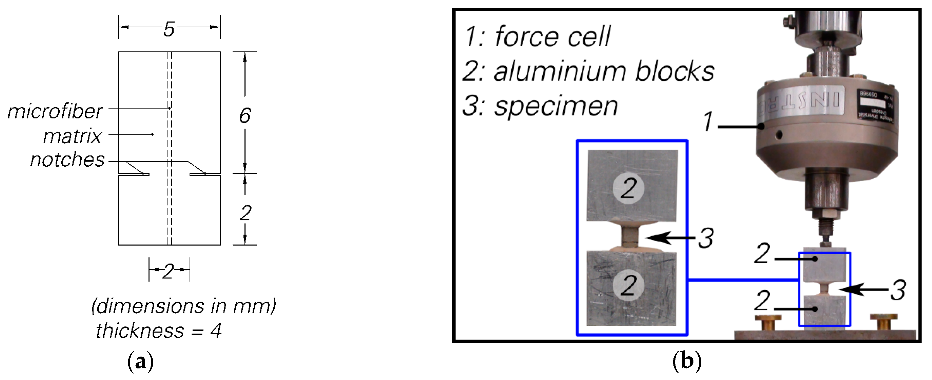
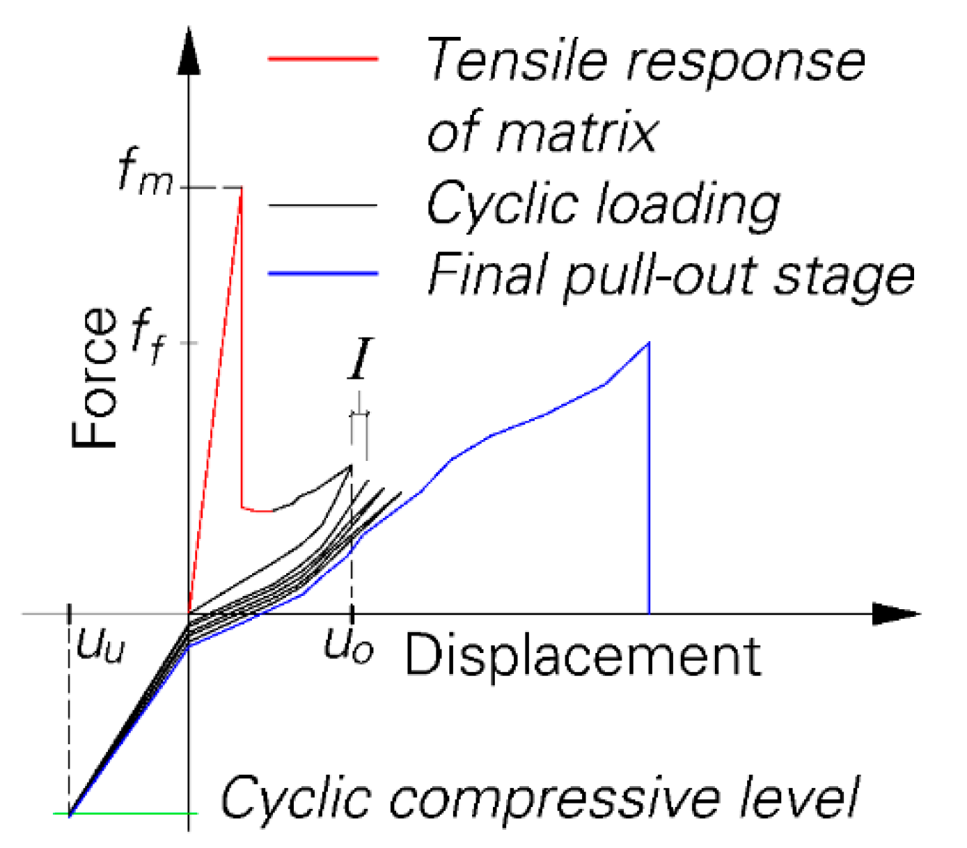
3. Test Setup
4. Experimental Programme
5. Results and Discussion
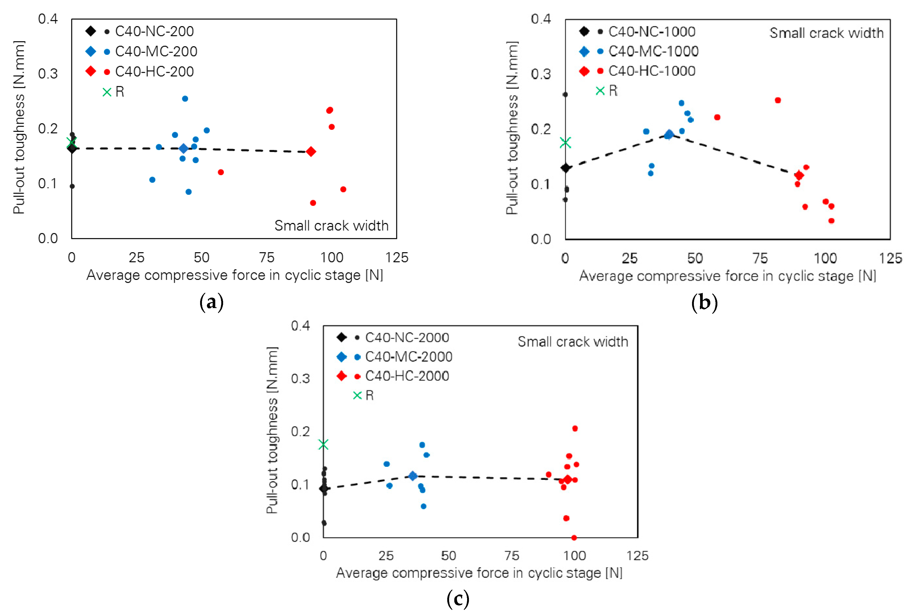
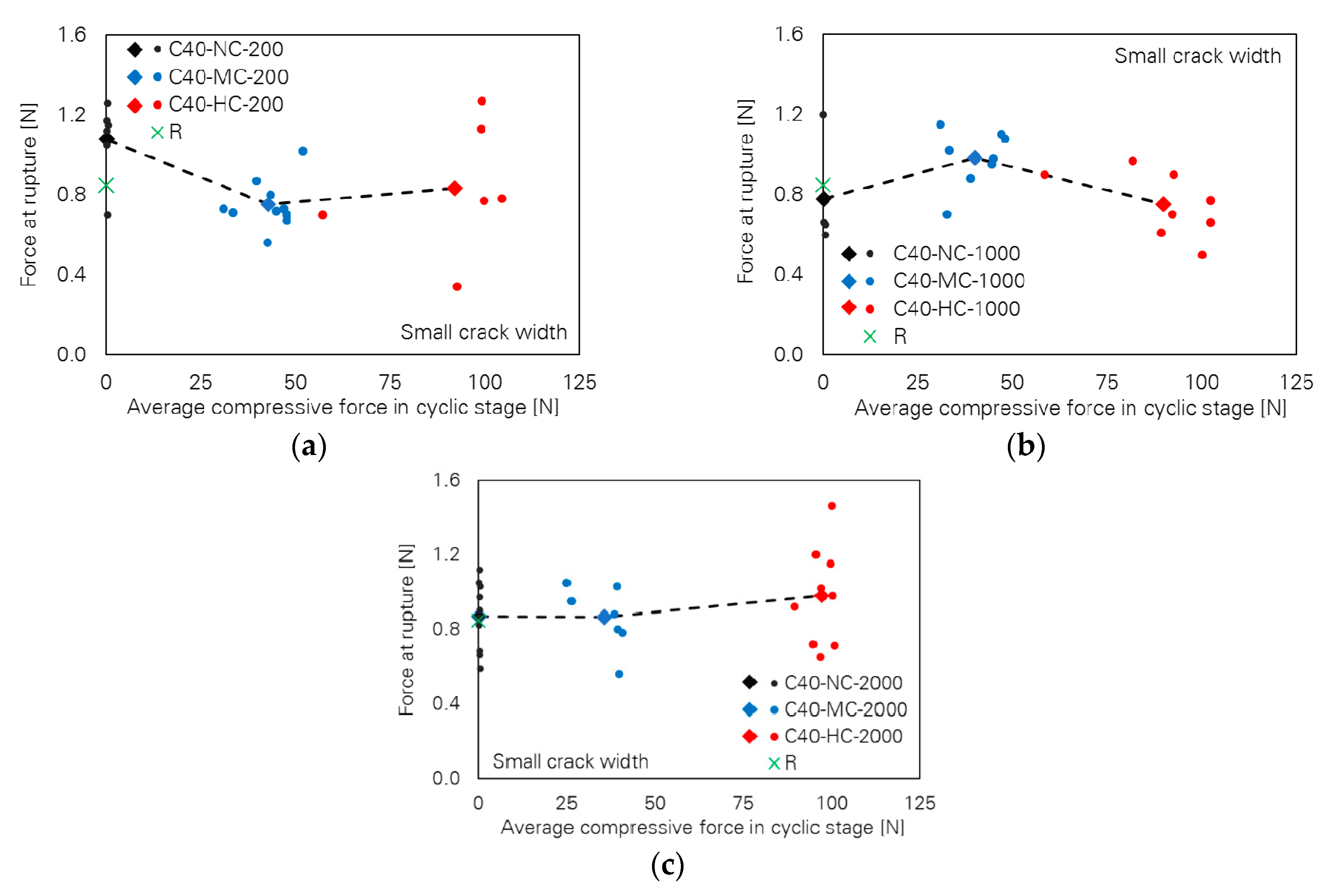
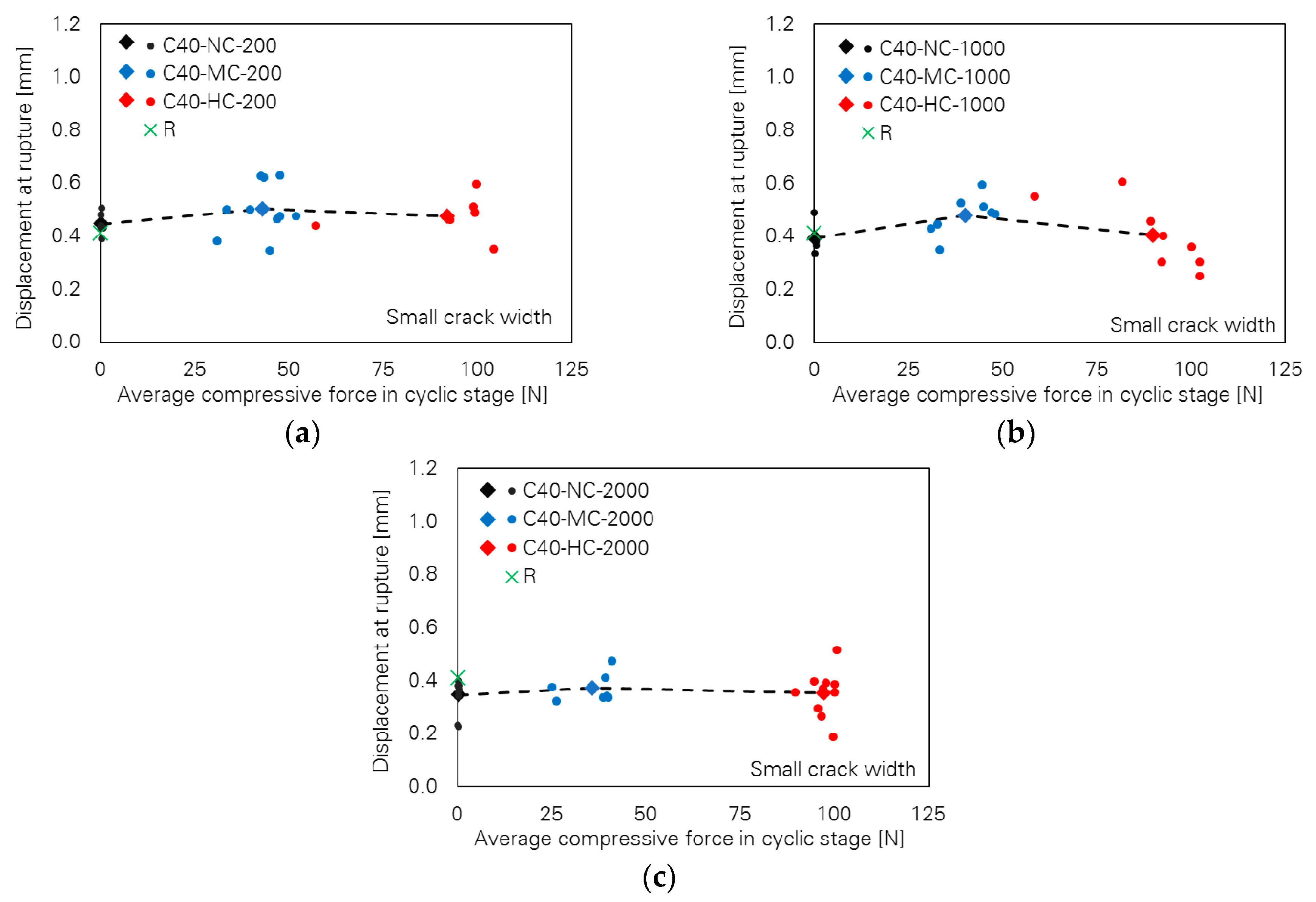
5.1. Small Crack Width
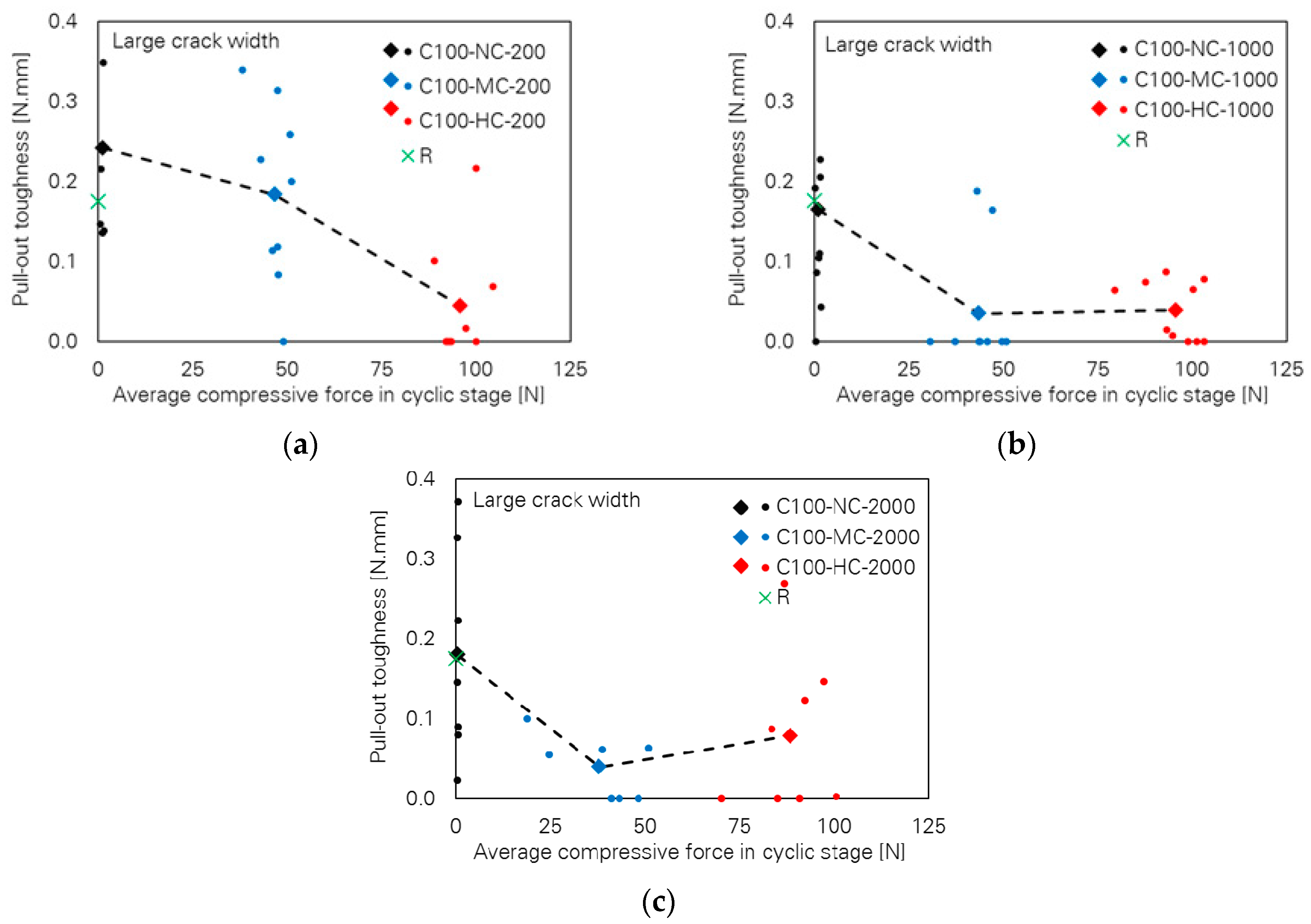
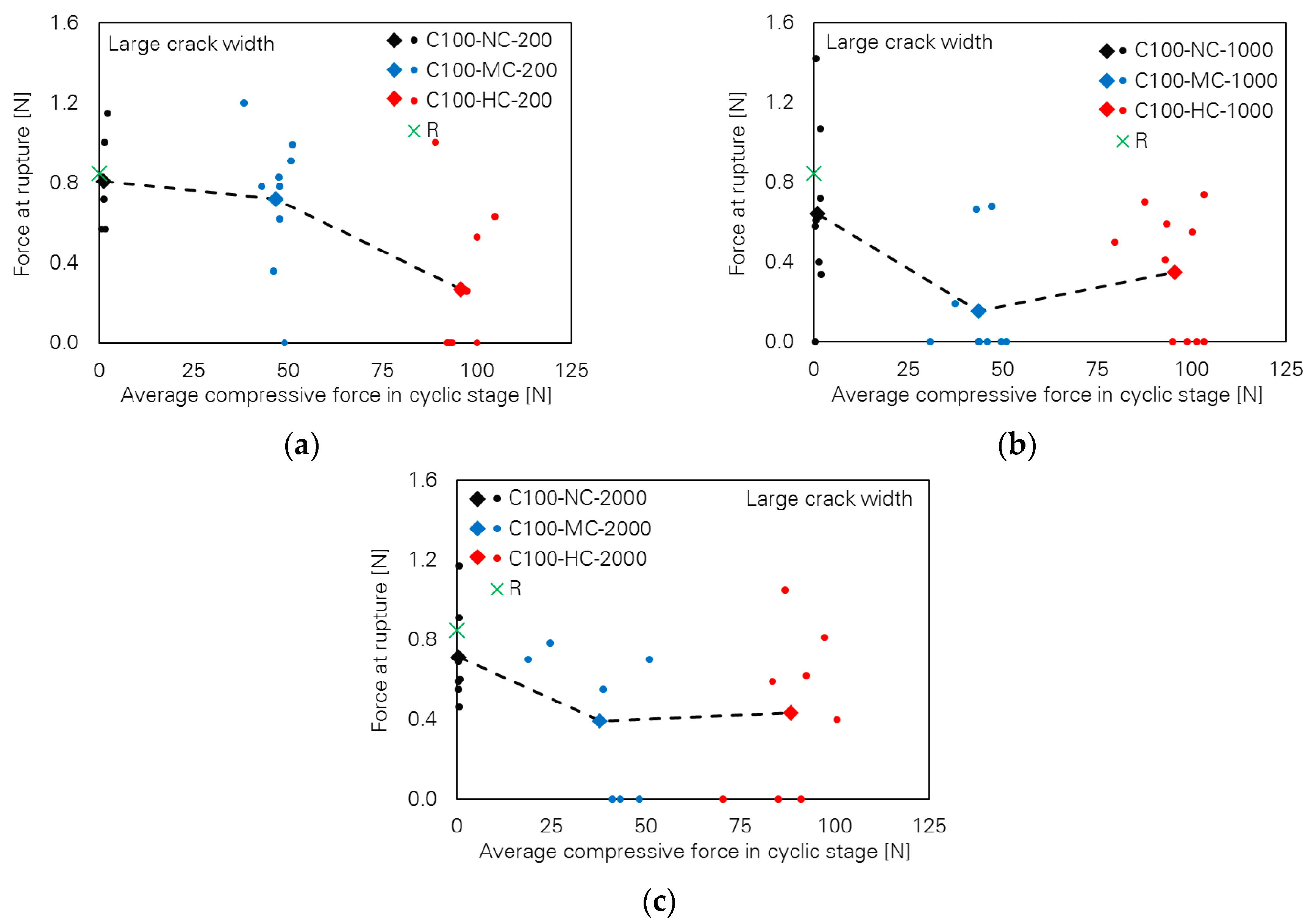
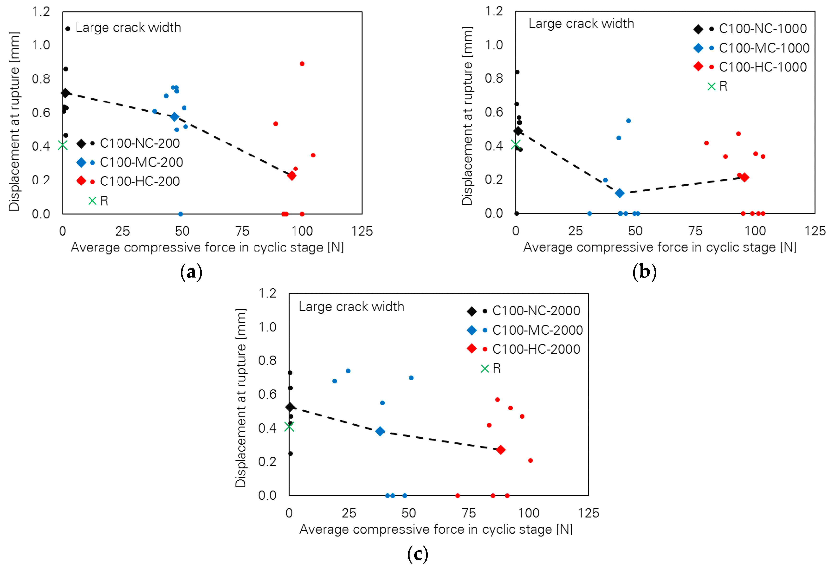
5.2. Large Crack Width
5.3. Joint Influence of Crack Width and Loading Parameters
6. Joint Influence of Crack Width and Loading Parameters
7. Conclusions
Author Contributions
Funding
Acknowledgments
Conflicts of Interest
References
- Mechtcherine, V. Novel cement-based composites for the strengthening and repair of concrete structures. Constr. Build. Mater. 2013, 41, 365–373. [Google Scholar] [CrossRef]
- Zhan, K.; Yu, J.; Wang, Y.; Yu, K. Development of cementitious composites with tensile strain capacity up to 10%. In Proceedings of the International Conference on Strain-Hardening Cement-Based Composites, Dresden, Germany, 18–20 September 2017; pp. 147–153. [Google Scholar]
- Leung, C.K.Y. Performance-Based Design of SHCC Components—Research and Challenges. In Proceedings of the International Conference on Strain-Hardening Cement-Based Composites, Dresden, Germany, 18–20 September 2017; pp. 429–440. [Google Scholar]
- Leung, C.K.Y.; Li, V.C. Strength-based and fracture-based approaches in the analysis of fibre debonding. J. Mater. Sci. Lett. 1990, 9, 1140–1142. [Google Scholar] [CrossRef] [Green Version]
- Das, A.K.; Mishra, D.K.; Yu, J.; Leung, C.K.Y. Smart self-healing and self-sensing cementitious composites-recent developments, challenges, and prospects. Adv. Civ. Eng. 2019, 8, 554–578. [Google Scholar] [CrossRef]
- Yu, J.; Yao, J.; Lin, X.; Li, H.; Lam, J.Y.K.; Leung, C.K.Y.; Sham, I.M.L.; Shih, K. Tensile performance of sustainable Strain-Hardening Cementitious Composites with hybrid PVA and recycled PET fibers. Cem. Concr. Res. 2018, 107, 110–123. [Google Scholar] [CrossRef]
- Huang, B.-T.; Wu, J.; Yu, J.; Dai, J.-G.; Leung, C. High-Strength Seawater Sea-sand Engineered Cementitious Composites (SS-ECC): Mechanical Performance and Probabilistic Modeling. Cem. Concr. Compos. 2020, 103740. [Google Scholar] [CrossRef]
- Yu, J.; Leung, C. Sustainable PVA Fiber-Reinforced Strain-Hardening Cementitious Composites (SHCC) with Ultrahigh-Volume Limestone Calcined Clay. In Calcined Clays for Sustainable Concrete; Springer: Singapore, 2020; pp. 503–511. ISBN 978-981-15-2805-7. [Google Scholar]
- Lin, Z.; Kanda, T.; Li, V.C. On Interface Property Characterization and Performance of Fiber Reinforced Cementitious Composites. Concr. Sci. Eng. 1999, 1, 173–184. [Google Scholar]
- Redon, C.; Li, V.C.; Wu, C.; Hoshiro, H.; Saito, T.; Ogawa, A. Measuring and modifying interface properties of PVA fibers in ECC matrix. J. Mater. Civ. Eng. 2001, 13, 399–406. [Google Scholar] [CrossRef]
- Kang, J.; Bolander, J.E. Simulating crack width distributions in SHCC under tensile loading. In Proceedings of the VIII International conference on fracture mechanics of concrete and concrete structures, FraMCoS-8, Toledo, Spain, 10–14 March 2013; Volume 2013, pp. 1992–1998. [Google Scholar]
- Müller, S.; Mechtcherine, V. Fatigue behaviour of strain-hardening cement-based composites (SHCC). Cem. Concr. Res. 2017, 92, 75–83. [Google Scholar] [CrossRef]
- SASAKAWA, E. A New Synthetic Fiber, KURALON K-II: Its Characteristics and New Applications. Sen’i Gakkaishi 1998, 54, P21–P24. [Google Scholar] [CrossRef] [Green Version]
- Ranjbarian, M.; Mechtcherine, V. Influence of loading parameters in cyclic tension-compression regime on crack-bridging behaviour of PVA microfibres embedded in cement-based matrix. Constr. Build. Mater. 2019, 228, 1–16. [Google Scholar] [CrossRef]
- Hearle, J.W.S.; Lomas, B.; Cooke, W.D. Atlas of Fibre Fracture and Damage to Textiles; Elsevier: Amsterdam, The Netherlands, 1998. [Google Scholar]
- Van Zijl, G.P.A.G.; Boshoff, W.P.; Wagner, C.; Slowik, V. Introduction: Crack Distribution and Durability of SHCC. In A Framework for Durability Design with Strain-Hardening Cement-Based Composites (SHCC); Springer: Berlin/Heidelberg, Germany, 2017; pp. 1–26. [Google Scholar]
- Li, V.C.; Wang, S.; Wu, C. Tensile strain-hardening behavior of polyvinyl alcohol engineered cementitious composite (PVA-ECC). ACI Mater. J. Am. Concr. Inst. 2001, 98, 483–492. [Google Scholar]
- Lepech, M.; Li, V.C. Water permeability of cracked cementitious composites. In Proceedings of the ICF 11, Turin, Italy, 20–25 March 2005. Paper 4539 of Compendium of Papers (CD ROM). [Google Scholar]
- Wang, S.; Li, V.C. Polyvinyl alcohol fiber reinforced engineered cementitious composites: Material design and performances. In Proceedings of the Int’l Workshop on HPFRCC Structural Applications, Honolulu, HI, USA, 23–26 May 2005; pp. 1–8. [Google Scholar]
- Wagner, C.; Slowik, V.; Waldenburger, K. Dehnungsverfestigendes zementgebundenes Material für die Sanierung gerissener Betonflächen. Bautechnik 2008, 85, 49–56. [Google Scholar] [CrossRef]
- Boshoff, W.P.; Adendorff, C.J. Modelling SHCC cracking for durability. In Proceedings of the Fracture and Damage of Advanced Fibre-reinforced Cement-based Materials, Dresden, Germany, 30 August–3 September 2010; pp. 195–202. [Google Scholar]
- Van Zijl, G. Crack distribution characterisation towards a framework for durability design of SHCC. In Proceedings of the 2nd International RILEM Conference on Strain Hardening Cementitious Composites (SHCC2-Rio), Rio de Janeiro, Brazil, 12–14 December 2011; pp. 149–156. [Google Scholar]
- Van Zijl, G.P.A.G.; Slowik, V.; Toledo Filho, R.D.; Wittmann, F.H.; Mihashi, H. Comparative testing of crack formation in strain-hardening cement-based composites (SHCC). Mater. Struct. 2016, 49, 1175–1189. [Google Scholar] [CrossRef] [Green Version]
- Adendorff, C.J. The Time-Dependant Cracking Behaviour of Strain Hardening Cement-Based Composite; Stellenbosch University: Stellenbosch, South Africa, 2009. [Google Scholar]
- Boshoff, W.P.; Adendorff, C.J. Effect of sustained tensile loading on SHCC crack widths. Cem. Concr. Compos. 2013, 37, 119–125. [Google Scholar] [CrossRef]
- Boshoff, W.P. Cracking behavior of SHCC subjected to sustained tensile loading. ACI Mater. J. 2014, 111, 553–560. [Google Scholar]
- Ranjbarian, M.; Mechtcherine, V. A novel test setup for the characterization of bridging behaviour of single microfibres embedded in a mineral-based matrix. Cem. Concr. Compos. 2018, 92, 92–101. [Google Scholar] [CrossRef]
- Ranjbarian, M.; Mechtcherine, V. Cyclic Damage on PVA Microfibre Embedded in Cementitious Matrix in Alternating Tension-Compression Regime. In Proceedings of the FRC2018: Fibre Reinforced Concrete: From Design to Structural Applications Joint ACI-fib-RILEM International Workshop, Garda, Italy, 27–30 June 2018. [Google Scholar]
- Boshoff, W.P.; Mechtcherine, V.; van Zijl, G.P.A.G. Characterising the time-dependant behaviour on the single fibre level of SHCC: Part 1: Mechanism of fibre pull-out creep. Cem. Concr. Res. 2009, 39, 779–786. [Google Scholar] [CrossRef]
- Jun, P.; Mechtcherine, V. Behaviour of strain-hardening cement-based composites (SHCC) under monotonic and cyclic tensile loading: Part 1—experimental investigations. Cem. Concr. Compos. 2010, 32, 801–809. [Google Scholar] [CrossRef]
- Ranjbarian, M.; Mechtcherine, V.; Zhang, Z.; Curosu, I.; Storm, J.; Kaliske, M. Locking Front Model for pull-out behaviour of PVA microfibre embedded in cementitious matrix. Cem. Concr. Compos. 2019. [Google Scholar] [CrossRef]
- Ranjbarian, M.; Mechtcherine, V. Pilot Investigation into Crack Bridging Behaviour of Different Types of High-Performance Microfibres under Reversed Tension-Compression Loading. In Proceedings of the fib Symposium 2019, Concrete-Innovations in Materials, Design and Structures, Krakow, Poland, 27–29 May 2019; pp. 121–128. [Google Scholar]


| Cement CEM I 42.5 R-HS | Fly Ash (Steament H4) | Water | Quartz Sand (0.06–0.2 mm) | Superplasticizer (Glenium ACE30, BASF) | Viscosity Agent |
|---|---|---|---|---|---|
| 505 | 621 | 338 | 536 | 10 | 4.8 |
| Fibre Type | Nominal Diameter [µm] | Density [g/cm3] | Tensile Strength [MPa] | Young’s Modulus [GPa] | Strain Capacity [-] |
|---|---|---|---|---|---|
| Kuralon K-II REC 15 (Kuraray) | 40 | 1.3 | 1600 | 40 | 0.06 |
| Test Series | Crack Width in Cyclic Stage (UO) [µm] | Lower Reversal Point (UU) [mm] | Displacement Increment Per Cycle (I) [µm] | Number of Cycles [-] | Number of Successfully Tested Specimens | |
|---|---|---|---|---|---|---|
| Start | End | |||||
| R | - | - | - | - | - | 11 |
| C40-NC-200 | 40 | 60 | 0.020 | 0.10 | 200 | 7 |
| C40-MC-200 | −0.010 | 10 | ||||
| C40-HC-200 | −0.025 | 10 | ||||
| C40-NC-1000 | 0.020 | 0.02 | 1000 | 4 | ||
| C40-MC-1000 | −0.010 | 10 | ||||
| C40-HC-1000 | −0.025 | 10 | ||||
| C40-NC-2000 | 0.020 | 0.01 | 2000 | 10 | ||
| C40-MC-2000 | −0.010 | 10 | ||||
| C40-HC-2000 | −0.025 | 10 | ||||
| C100-NC-200 | 100 | 200 | 0.020 | 0.50 | 200 | 10 |
| C100-MC-200 | −0.010 | 10 | ||||
| C100-HC-200 | −0.025 | 9 | ||||
| C100-NC-1000 | 0.020 | 0.10 | 1000 | 11 | ||
| C100-MC-1000 | −0.010 | 11 | ||||
| C100-HC-1000 | −0.025 | 10 | ||||
| C100-NC-2000 | 0.020 | 0.05 | 2000 | 10 | ||
| C100-MC-2000 | −0.010 | 8 | ||||
| C100-HC-2000 | −0.025 | 8 | ||||
| Series | Number of Specimens | ||||
|---|---|---|---|---|---|
| Total | Fibre Rupture with One-Way Full Debonding and Slippage | Fibre Rupture with Two-Way Full Debonding and Slippage | Complete Fibre Pull-Out | Fibre Rupture in Cyclic Stage | |
| R | 11 | 9 | 2 | 0 | - |
| C40-NC-200 | 7 | 6 | 1 | 0 | 0 |
| C40-MC-200 | 10 | 10 | 0 | 0 | 0 |
| C40-HC-200 | 10 | 6 | 2 | 2 | 0 |
| C40-NC-1000 | 4 | 4 | 0 | 0 | 0 |
| C40-MC-1000 | 10 | 8 | 2 | 0 | 0 |
| C40-HC-1000 | 10 | 8 | 1 | 1 | 0 |
| C40-NC-2000 | 10 | 10 | 0 | 0 | 0 |
| C40-MC-2000 | 10 | 7 | 2 | 1 | 0 |
| C40-HC-2000 | 10 | 10 | 0 | 0 | 0 |
| C100-NC-200 | 10 | 6 | 1 | 3 | 0 |
| C100-MC-200 | 10 | 9 | 0 | 1 | 1 |
| C100-HC-200 | 9 | 9 | 0 | 0 | 5 |
| C100-NC-1000 | 11 | 9 | 0 | 2 | 1 |
| C100-MC-1000 | 11 | 10 | 0 | 1 | 6 |
| C100-HC-1000 | 10 | 10 | 0 | 0 | 4 |
| C100-NC-2000 | 10 | 7 | 3 | 0 | 0 |
| C100-MC-2000 | 8 | 7 | 1 | 0 | 3 |
| C100-HC-2000 | 8 | 8 | 0 | 0 | 3 |
| No Compressive Force | Moderate Compressive Force | High Compressive Force |
|---|---|---|
| C100-NC-200 | C100-MC-200 | C100-HC-200 |
| no fibre rupture | 162 | 171 166 129 185 166 |
| C100-NC-1000 | C100-MC-1000 | C100-HC-1000 |
| 752 | 900 625 937 890 392 573 | 408 643 653 846 |
| C100-NC-2000 | C100-MC-2000 | C100-HC-2000 |
| no fibre rupture | 1132 1190 1514 | 1539 1633 1193 |
| Test Series | Pull-Out Toughness [N mm] | Force at Fibre Rupture [N] | Displacement at Rupture [N] | Average Maximum Force in Fibre in Cyclic Stage [N] | Average Minimum Force in Fibre in Cyclic Stage [N] |
|---|---|---|---|---|---|
| R | 0.176 (0.060) | 0.847 (0.181) | 0.411 (0.088) | - | - |
| C40-NC-200 | 0.164 (0.031) | 1.075 (0.179) | 0.446 (0.037) | 0.363 (0.046) | −0.317 (0.177) |
| C40-MC-200 | 0.164 (0.045) | 0.751 (0.118) | 0.502 (0.094) | 0.225 (0.056) | −42.928 (6.244) |
| C40-HC-200 | 0.158 (0.069) | 0.832 (0.302) | 0.474 (0.074) | 0.157 (0.070) | −92.083 (15.966) |
| C40-NC-1000 | 0.130 (0.078) | 0.778 (0.245) | 0.393 (0.059) | 0.168 (0.069) | −0.306 (0.225) |
| C40-MC-1000 | 0.191 (0.042) | 0.983 (0.134) | 0.479 (0.068) | 0.201 (0.061) | −40.106 (6.514) |
| C40-HC-1000 | 0.117 (0.076) | 0.751 (0.153) | 0.403 (0.117) | 0.152 (0.063) | −89.920 (13.612) |
| C40-NC-2000 | 0.092 (0.034) | 0.868 (0.171) | 0.345 (0.061) | 0.246 (0.138) | −0.335 (0.131) |
| C40-MC-2000 | 0.117 (0.038) | 0.864 (0.157) | 0.370 (0.051) | 0.151 (0.036) | −35.684 (6.352) |
| C40-HC-2000 | 0.110 (0.055) | 0.978 0.237 | 0.351 0.083 | 0.218 0.106 | −97.188 3.202 |
| C100-NC-200 | 0.242 (0.125) | 0.807 (0.214) | 0.717 (0.206) | 0.260 (0.059) | −1.291 (0.519) |
| C100-MC-200 | 0.184 (0.107) | 0.719 (0.336) | 0.577 (0.222) | 0.272 (0.091) | −46.823 (3.795) |
| C100-HC-200 | 0.045 (0.070) | 0.269 (0.349) | 0.227 (0.300) | 0.335 (0.100) | −95.733 (4.717) |
| C100-NC-1000 | 0.165 (0.143) | 0.641 (0.389) | 0.488 (0.216) | 0.229 (0.069) | −1.045 (0.556) |
| C100-MC-1000 | 0.035 (0.071) | 0.154 (0.266) | 0.120 (0.200) | 0.352 (0.087) | −43.544 (5.589) |
| C100-HC-1000 | 0.038 (0.036) | 0.349 (0.298) | 0.216 (0.186) | 0.287 (0.070) | −95.496 (7.184) |
| C100-NC-2000 | 0.180 (0.122) | 0.710 (0.229) | 0.526 (0.149) | 0.246 (0.069) | −0.510 (0.104) |
| C100-MC-2000 | 0.040 (0.037) | 0.390 (0.344) | 0.381 (0.335) | 0.344 (0.062) | −37.954 (11.063) |
| C100-HC-2000 | 0.079 (0.092) | 0.434 (0.378) | 0.274 (0.234) | 0.234 (0.043) | −88.367 (8.788) |
© 2020 by the authors. Licensee MDPI, Basel, Switzerland. This article is an open access article distributed under the terms and conditions of the Creative Commons Attribution (CC BY) license (http://creativecommons.org/licenses/by/4.0/).
Share and Cite
Ranjbarian, M.; Ma, X.; Mechtcherine, V. Influence of Crack Width in Alternating Tension–Compression Regimes on Crack-Bridging Behaviour and Degradation of PVA Microfibres Embedded in Cement-Based Matrix. Materials 2020, 13, 4189. https://doi.org/10.3390/ma13184189
Ranjbarian M, Ma X, Mechtcherine V. Influence of Crack Width in Alternating Tension–Compression Regimes on Crack-Bridging Behaviour and Degradation of PVA Microfibres Embedded in Cement-Based Matrix. Materials. 2020; 13(18):4189. https://doi.org/10.3390/ma13184189
Chicago/Turabian StyleRanjbarian, Majid, Xiaomeng Ma, and Viktor Mechtcherine. 2020. "Influence of Crack Width in Alternating Tension–Compression Regimes on Crack-Bridging Behaviour and Degradation of PVA Microfibres Embedded in Cement-Based Matrix" Materials 13, no. 18: 4189. https://doi.org/10.3390/ma13184189