Prepregs for Temperature Resistant Composites


Abstract
:
1. Introduction
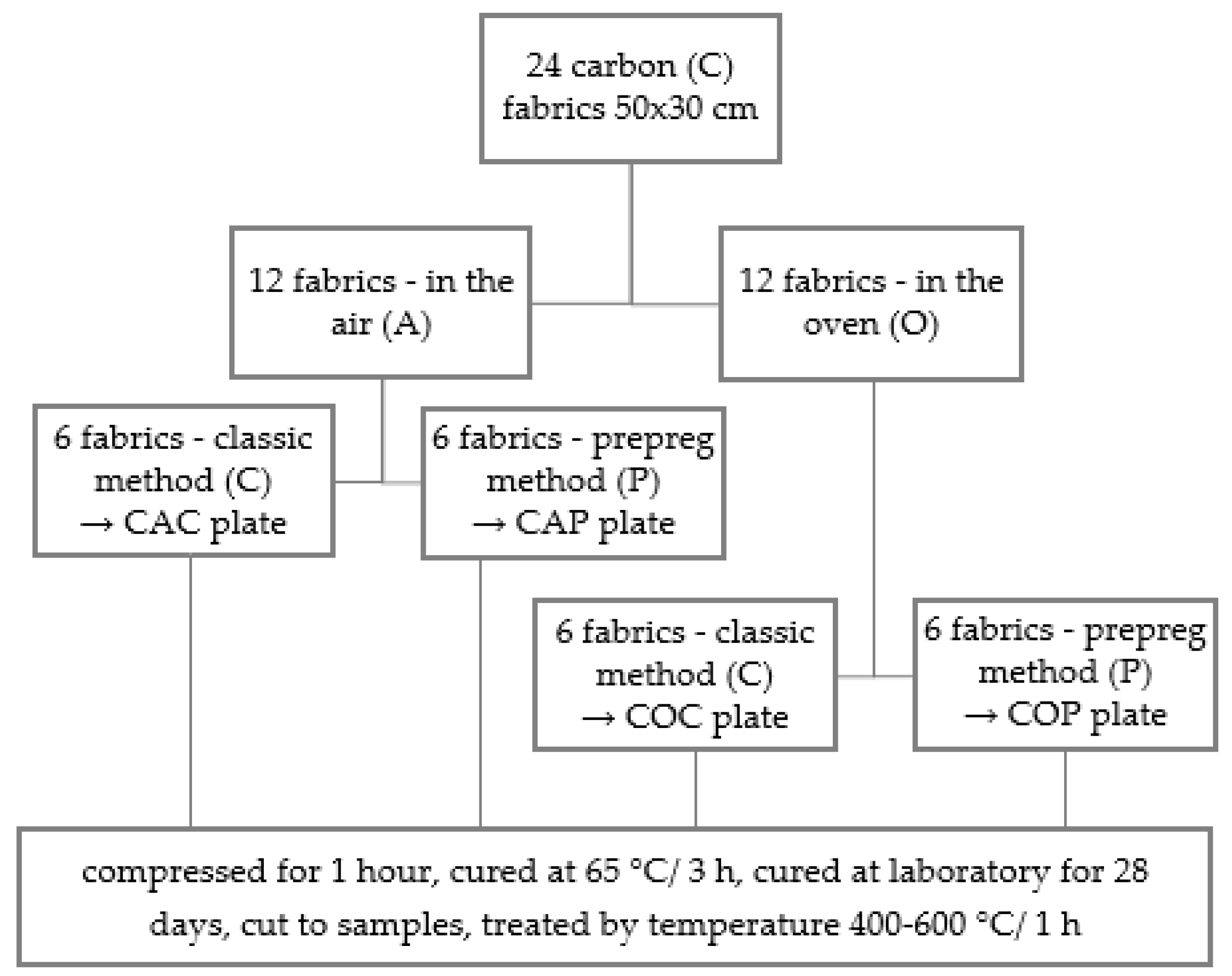
2. Materials and Methods
3. Results and Discussion
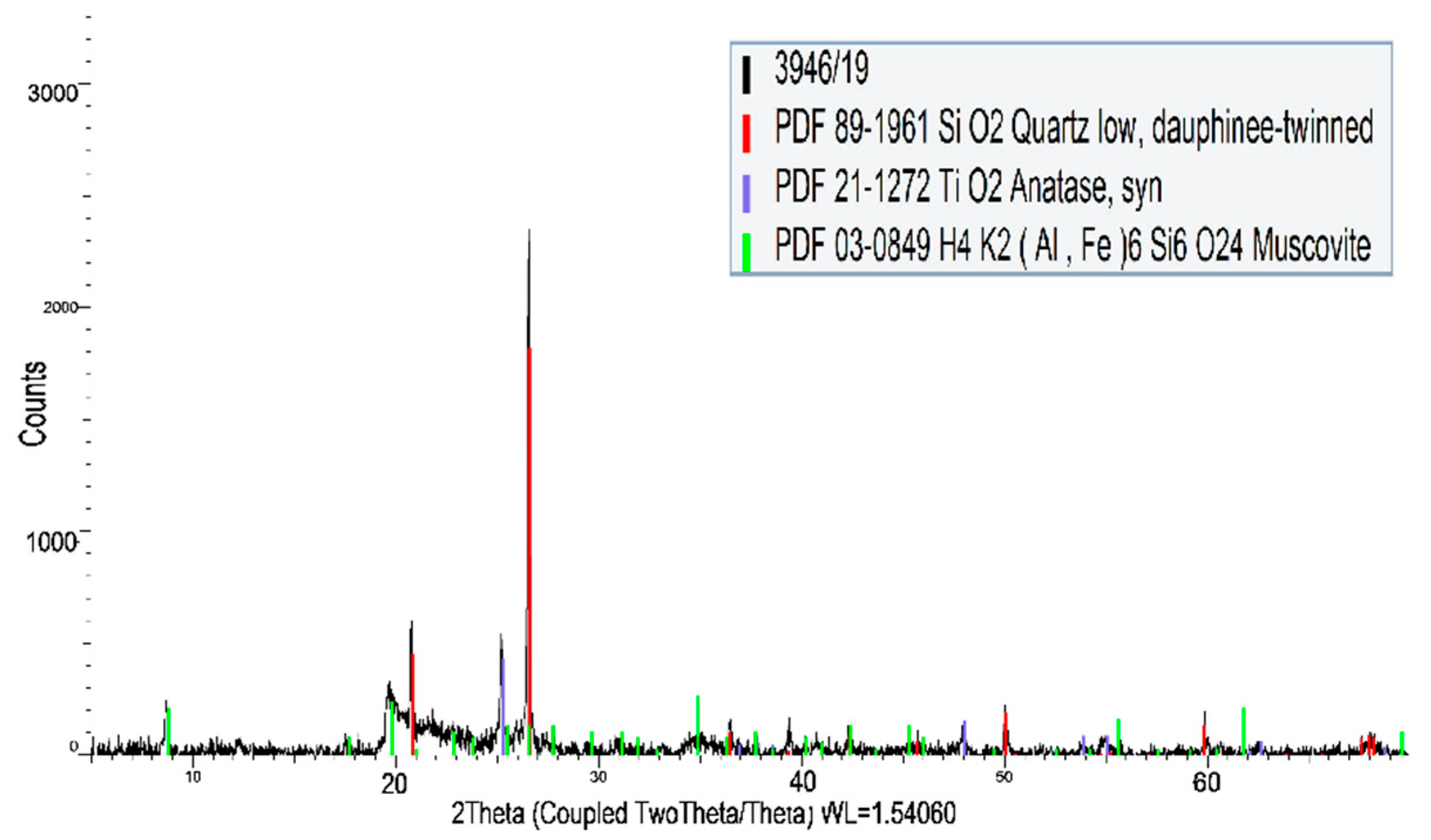
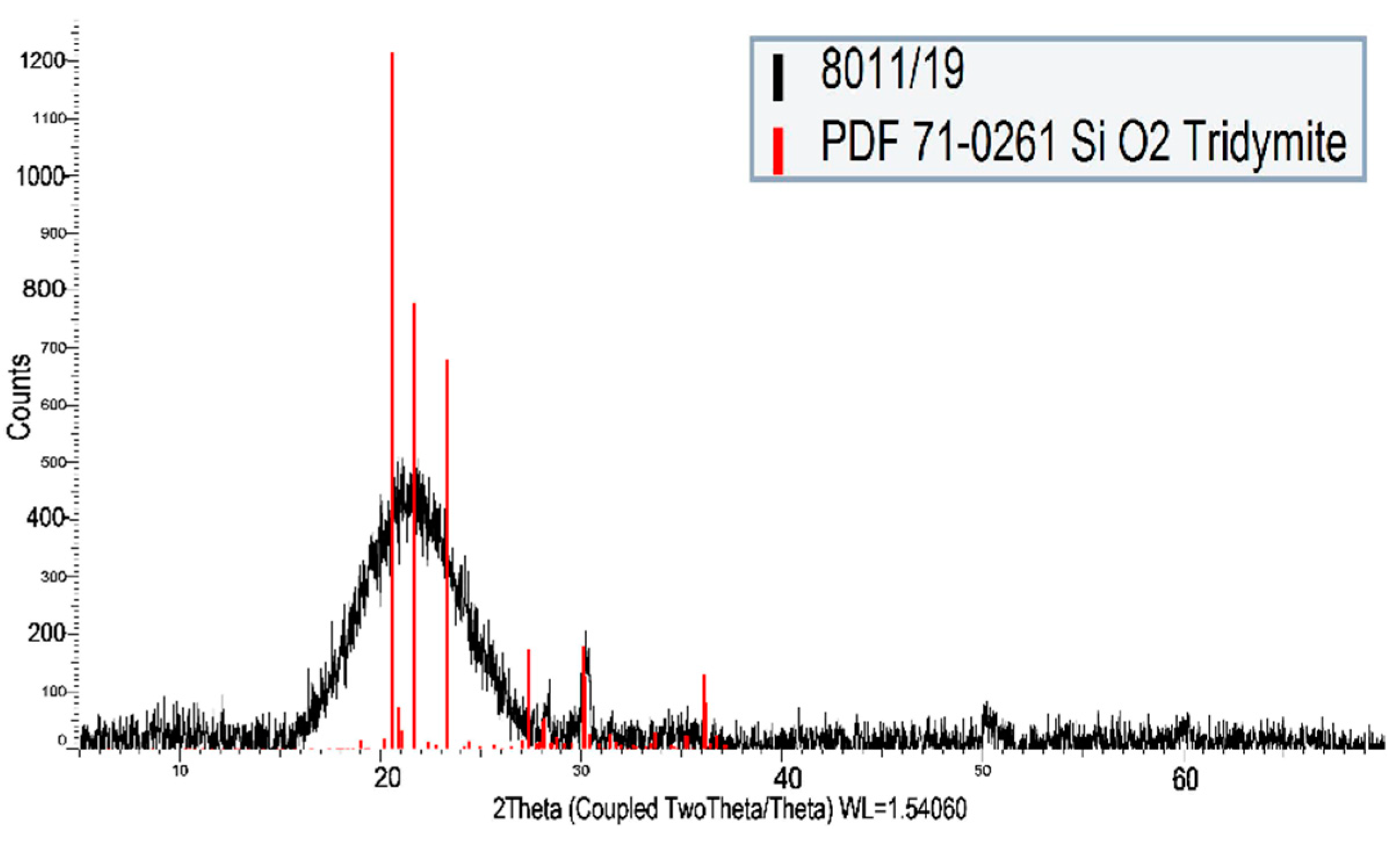
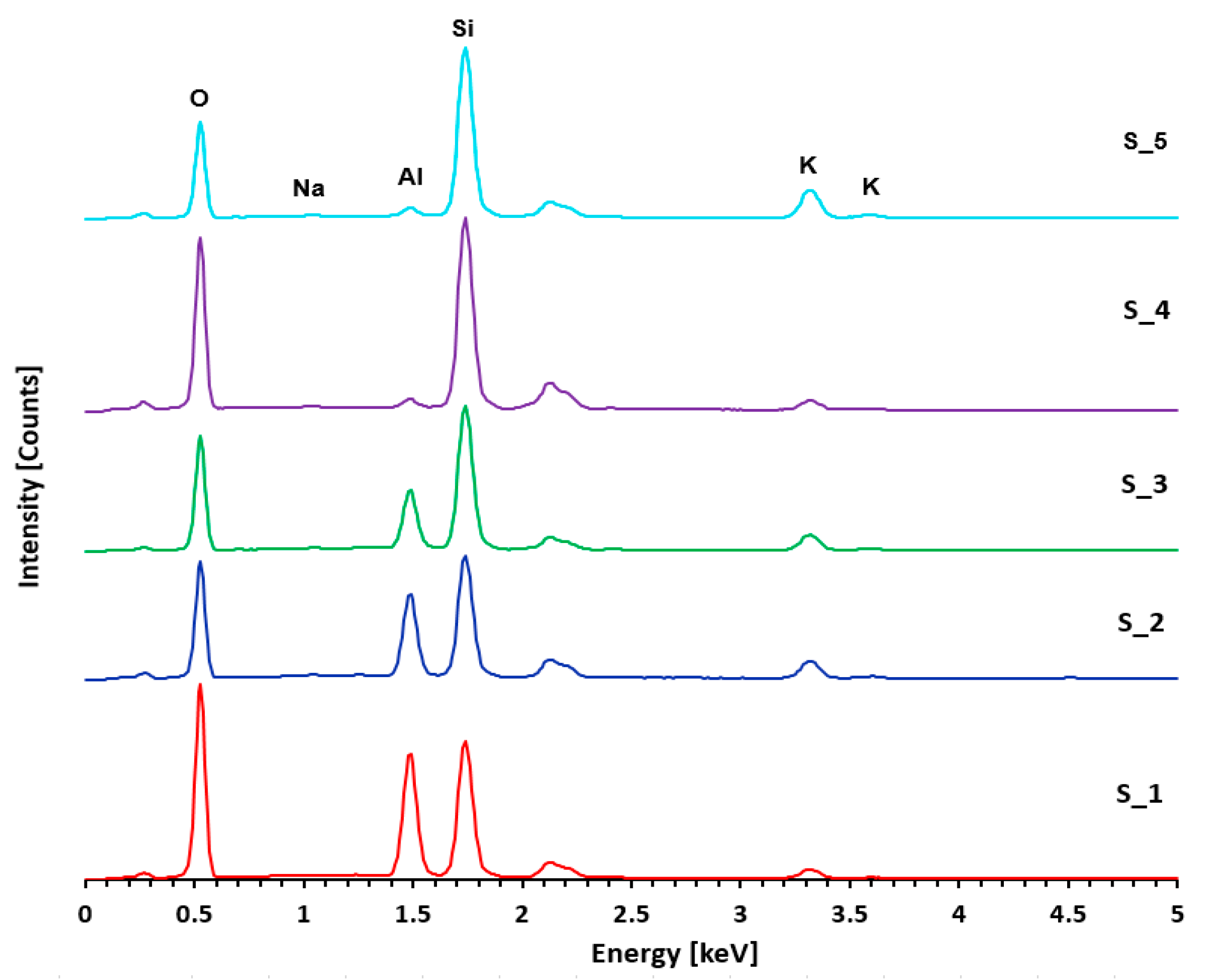
3.1. A-Matrix
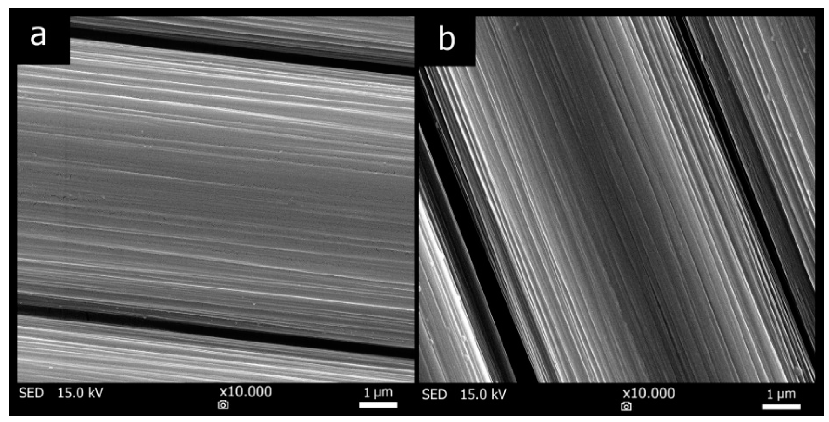
3.2. Carbon Fabric
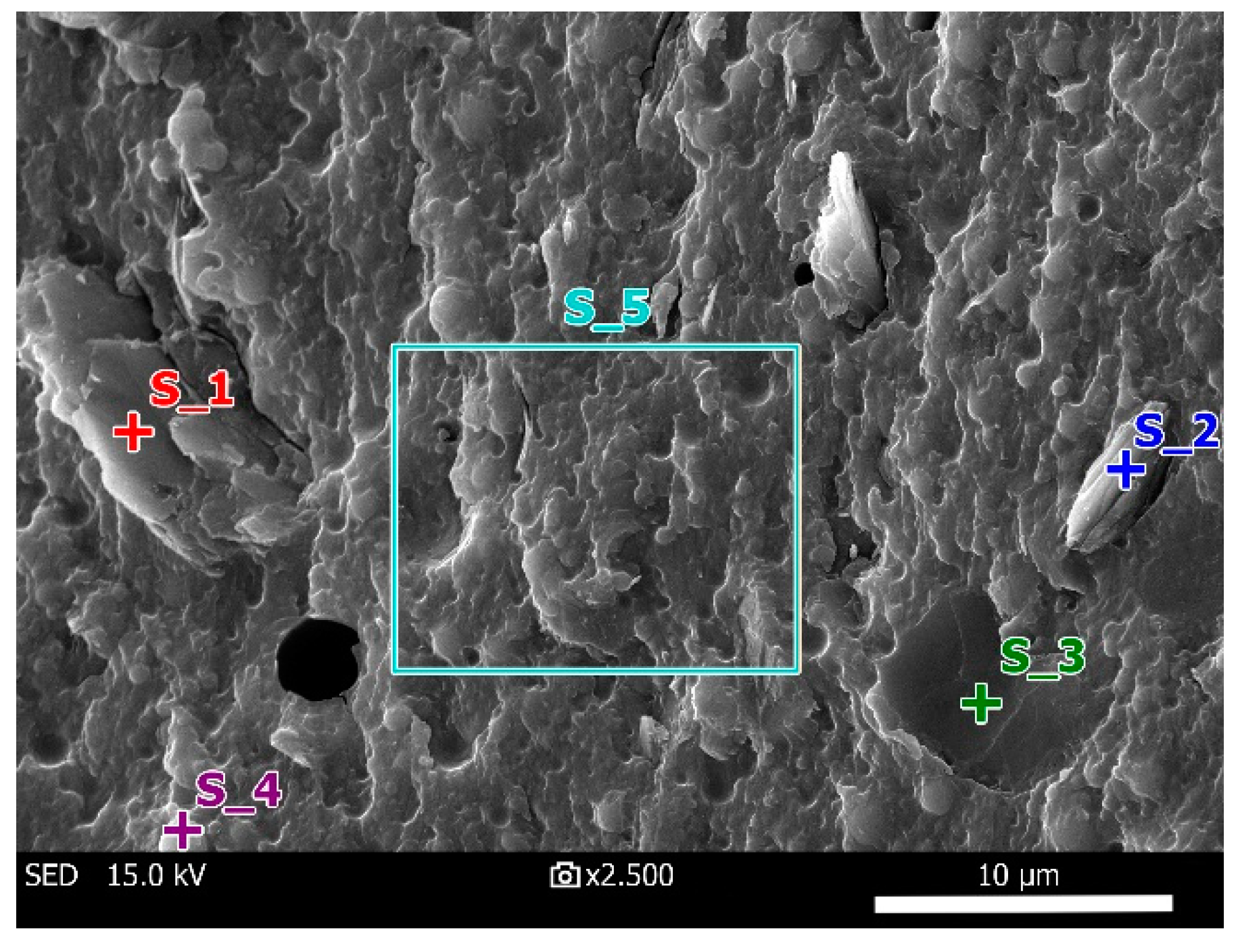
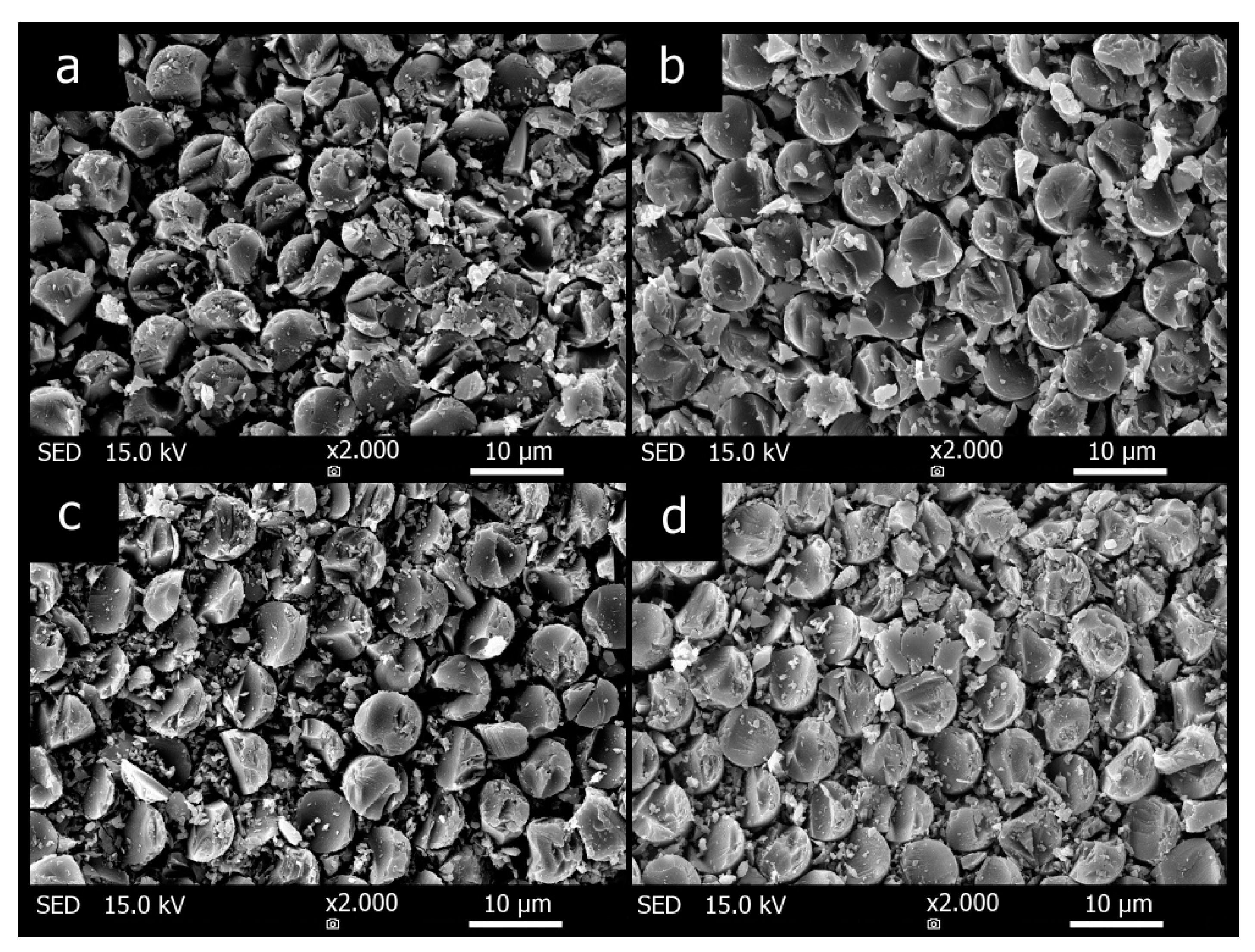
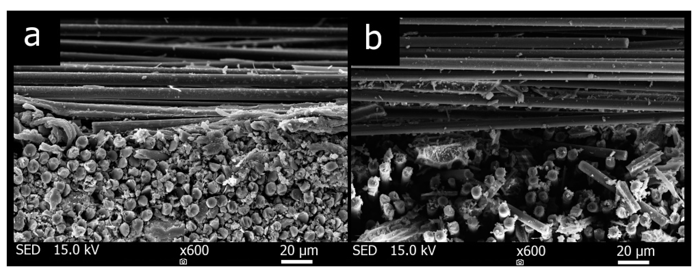
3.3. Composite Surface
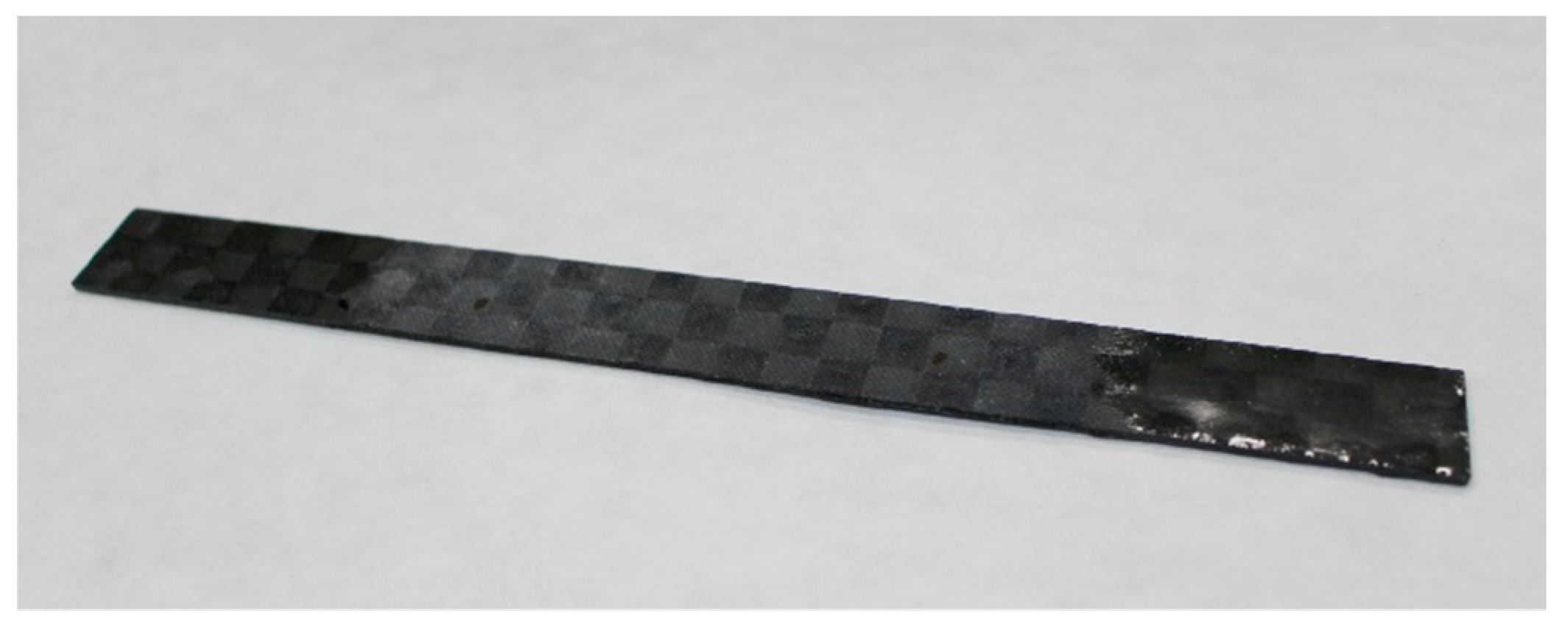
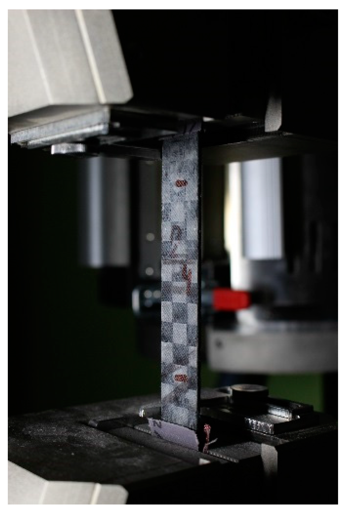
3.4. Tensile Properties of Composites
4. Conclusions
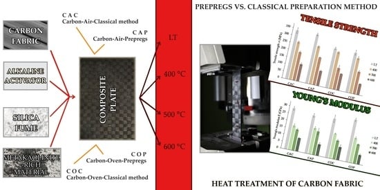
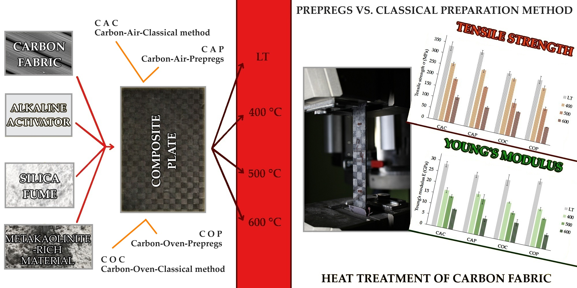
- All four types of composites showed homogenous microstructure and carbon fabric was well infiltrated by the inorganic aluminosilicate matrix independent of the fiber treatment or preparation method.
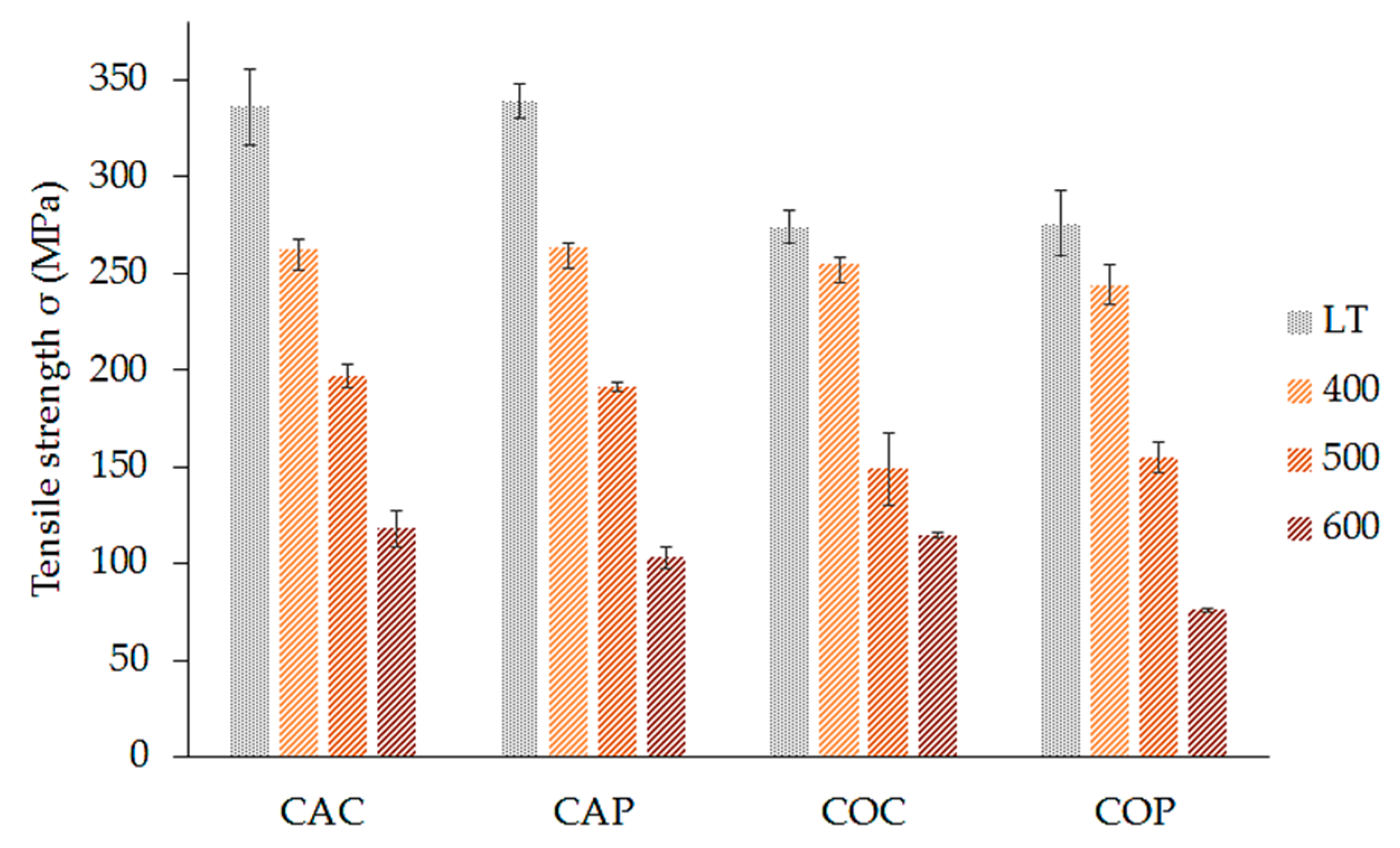
- The highest tensile strength was seen in samples prepared without fiber heat treatment, with classic lay-up samples exhibiting a strength of 336 ± 19 MPa and prepreg prepared samples exhibiting a strength of 339 ± 9 MPa.
- The composites lost high tensile strength with increasing curing temperature, but they retained 30–40 % of their original strength at 600 °C.
- Significant decrease in tensile strength of samples with heat treated fabric. Therefore, removal of the organic sizing by elevated temperature did not show any positive effects.
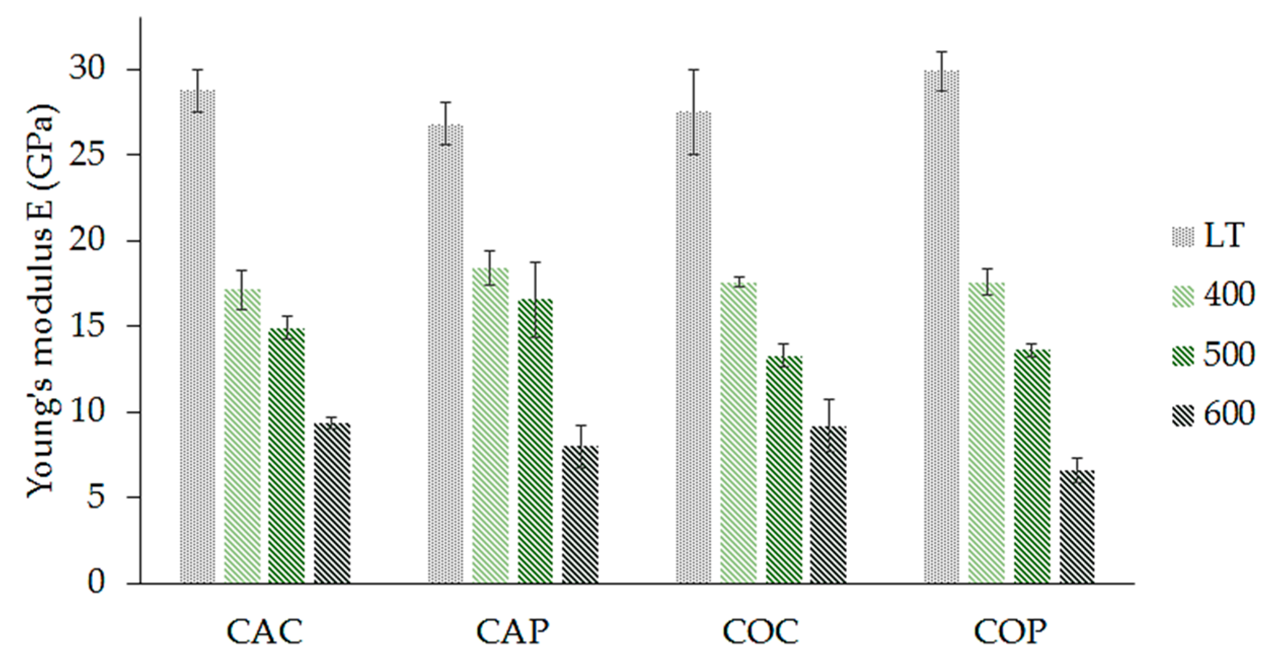
- The method of preparation of composite had no significant effect on the tensile strength or Young’s modulus of the samples. The prepreg method of composite preparation is, in terms of tensile properties, a good substitute for classic composite preparation.
Author Contributions
Funding
Conflicts of Interest
References
- Sun, G.; Tong, S.; Chen, D.; Gong, Z.; Li, Q. Mechanical properties of hybrid composites reinforced by carbon and basalt fibers. Int. J. Mech. Sci. 2018, 148, 636–651. [Google Scholar] [CrossRef]
- Krystek, J.; Kroupa, T.; Kottner, R. Identification of mechanical properties from tensile and compression tests of unidirectional carbon composite. In Proceedings of the 48th International Scientific Conference on Experimental Stress Analysis, Olomouc, Czech, 31 May–3 June 2010. [Google Scholar]
- Papakonstantinou, C.G.; Balaguru, P.; Lyon, R.E. Comparative study of high temperature composites. Compos. Part B 2001, 32, 637–649. [Google Scholar] [CrossRef]
- Tran, T.Q.; Lee, J.K.Y.; Chinnappan, A.; Jayathilaka, W.A.D.M.; Ji, D.; Kumar, V.V.; Ramakrishna, S. Strong, Lightweight, and Highly Conductive CNT/Au/Cu Wires from Sputtering and Electroplating Methods. J. Mater. Sci. Technol. 2019, in press. [Google Scholar] [CrossRef]
- Duong, H.M.; Myint, S.M.; Tran, T.Q.; Le, D.K. Post-spinning treatments to carbon nanotube fibers. In Carbon Nanotube Fibers and Yarns; Woodhead Publishing: London, UK, 2020; pp. 103–134. [Google Scholar]
- Yan, S.; He, P.; Zhang, Y.; Jia, D.; Wang, J.; Duan, X.; Yang, Z.; Zhou, Y. Preparation and in-situ high-temperature mechanical properties of Cf-SiCf reinforced geopolymer composites. Ceram. Int. 2017, 43, 549–555. [Google Scholar] [CrossRef]
- Silva, F.J.; Thaumaturgo, C. Fibre reinforcement and fracture response in geopolymeric mortars. Fatique Fract Enging Struct 2003, 26, 167–172. [Google Scholar] [CrossRef]
- Duxson, P.; Provis, J.L.; Lukey, G.C.; Mallicoat, S.W.; Kriven, W.M.; van Deventer, J.S.J. Understanding the relationship between geopolymer composition, microstructure and mechanical properties. Colloids Surf. A Physicochem. Eng. Asp. 2005, 269, 47–58. [Google Scholar] [CrossRef]
- Kuenzel, C.; Li, L.; Vandeperre, L.; Boccaccini, A.R.; Cheeseman, C.R. Influence of sand on the mechanical properties of metakaolin geopolymers. Constr. Build. Mater. 2014, 66, 442–446. [Google Scholar] [CrossRef]
- Kuenzel, C.; Vandeperre, L.J.; Donatello, S.; Boccaccini, A.R.; Cheeseman, C.; Brown, P. Ambient Temperature Drying Shrinkage and Cracking in Metakaolin-Based Geopolymers. J. Am. Ceram. Soc. 2012, 95, 3270–3277. [Google Scholar] [CrossRef] [Green Version]
- Duxson, P.; Mallicoat, S.W.; Lukey, G.C.; Kriven, W.M.; van Deventer, J.S.J. The effect of alkali and Si/Al ratio on the development of mechanical properties of metakaolin-based geopolymers. Colloids Surf. A Physicochem. Eng. Asp. 2007, 292, 8–20. [Google Scholar] [CrossRef]
- Aredes, F.G.M.; Campos, T.M.B.; Machado, J.P.B.; Sakane, K.K.; Thim, G.P.; Brunelli, D.D. Effect of cure temperature on the formation of metakaolinite-based geopolymer. Ceram. Int. 2015, 41, 7302–7311. [Google Scholar] [CrossRef]
- Barbosa, V.F.F.; MacKenzie, K.J.D. Thermal behaviour of inorganic geopolymers and composites derived from sodium polysialete. Mater. Res. Bull. 2003, 38, 319–331. [Google Scholar] [CrossRef]
- Kovářík, T.; Rieger, D.; Kadlec, J.; Křenek, T.; Kullová, L.; Pola, M.; Bělský, P.; Franče, P.; Říha, J. Thermomechanical properties of particle-reinforced geopolymer composite with various aggregate gradation of fine ceramic filler. Constr. Build. Mater. 2017, 143, 599–606. [Google Scholar] [CrossRef]
- He, P.; Jia, D.; Lin, T.; Wang, M.; Zhou, Y. Effects of high-temperature heat treatment on the mechanical properties of unidirectional carbon fiber reinforced geopolymer composites. Ceram. Int. 2010, 36, 1447–1453. [Google Scholar] [CrossRef]
- He, P.; Jia, D.; Wang, M.; Zhou, Y. Improvement of high-temperature mechanical properties of heat treated Cf/geopolymer composites by Sol-SiO2 impregnation. J. Eur. Ceram. Soc. 2010, 30, 3053–3061. [Google Scholar] [CrossRef]
- Dias, D.P.; Thaumaturgo, C. Fracture toughness of geopolymeric concretes reinforced with basalt fibers. Cem. Concr. Compos. 2005, 27, 49–54. [Google Scholar] [CrossRef]
- Amaro, A.M.; Pinto, M.I.M.; Reis, P.N.B.; Neto, M.A.; Lopes, S.M.R. Structural integrity of glass/epoxy composites embedded in cement or geopolymer mortars. Compos. Struct. 2018, 206, 509–516. [Google Scholar] [CrossRef]
- Samal, S.; Marvalová, B.; Petríková, I.; Vallons, K.A.M.; Lomov, S.V.; Rahier, H. Impact and post impact behavior of fabric reinforced geopolymer composite. Constr. Build. Mater. 2016, 127, 111–124. [Google Scholar] [CrossRef]
- Kong, D.L.Y.; Sanjayan, J.G. Damage behavior of geopolymer composites exposed to elevated temperatures. Cem. Concr. Compos. 2008, 30, 986–991. [Google Scholar] [CrossRef]
- Bernal, S.A.; Bejarano, J.; Garzón, C.; Mejía de Gutiérrez, R.; Delvasto, S.; Rodríguez, E.D. Performance of refractory aluminosilicate particle/fiber-reinforced geopolymer composites. Compos. Part B Eng. 2012, 43, 1919–1928. [Google Scholar] [CrossRef]
- Mills-Brown, J.; Potter, K.; Foster, S.; Batho, T. Thermal and tensile properties of polysialate composites. Ceram. Int. 2013, 39, 8917–8924. [Google Scholar] [CrossRef] [Green Version]
- Krystek, J.; Laš, V.; Pompe, V.; Hájková, P. Tensile and bending test of carbon/epoxy and carbon/geopolymer composites after temperature conditioning. MATEC Web Conf. 2018, 157. [Google Scholar] [CrossRef] [Green Version]
- Yan, S.; He, P.; Jia, D.; Yang, Z.; Duan, X.; Wang, S.; Zhou, Y. Effect of fiber content on the microstructure and mechanical properties of carbon fiber felt reinforced geopolymer composites. Ceram. Int. 2016, 42, 7837–7843. [Google Scholar] [CrossRef]
- Lin, T.; Jia, D.; He, P.; Wang, M.; Liang, D. Effects of fiber length on mechanical properties and fracture behavior of short carbon fiber reinforced geopolymer matrix composites. Mater. Sci. Eng. A 2008, 497, 181–185. [Google Scholar] [CrossRef]
- Yuan, J.; He, P.; Jia, D.; Yan, S.; Cai, D.; Xu, L.; Yang, Z.; Duan, X.; Wang, S.; Zhou, Y. SiC fiber reinforced geopolymer composites, part 1: Short SiC fiber. Ceram. Int. 2016, 42, 5345–5352. [Google Scholar] [CrossRef]
- Shin, J.H.; Kim, D.; Centea, T.; Nutt, S.R. Thermoplastic prepreg with partially polymerized matrix: Material and process development for efficient part manufacturing. Compos. Part A Appl. Sci. Manuf. 2019, 119, 154–164. [Google Scholar] [CrossRef]
- Hájková, P. Kaolinite Claystone-Based Geopolymer Materials: Effect of Chemical Composition and Curing Conditions. Minerals 2018, 8, 444. [Google Scholar] [CrossRef] [Green Version]


| Material | Material Composition (%) | ||||||||
|---|---|---|---|---|---|---|---|---|---|
| H2O | SiO2 | Al2O3 | Na2O | K2O | CaO | P2O5 | Fe2O3 | ZrO2 | |
| Metakaolinite-rich material | 1.26 | 52.3 | 42.6 | 0.77 | 0.18 | 0.08 | 0.81 | ||
| Silica fume | 0.62 | 93.8 | 0.15 | 0.04 | 0.09 | 0.43 | 1.56 | ||
| Potassium water glass | 44.5 | 28.5 | 1.12 | 24.2 | |||||
| Plate | Area (m2) of 1 Piece of Carbon Fabric (200 g/m2) | Weight of Composite Plate (g) | Carbon Fabric Reinforcement (wt. %) |
|---|---|---|---|
| CAC | 0.15 | 536.5 | 33.6 |
| CAP | 0.15 | 528.5 | 34.1 |
| COC | 0.15 | 525.0 | 34.3 |
| COP | 0.15 | 529.6 | 34.0 |
| Name | Composition (%) | ||||
|---|---|---|---|---|---|
| Na2O | Al2O3 | SiO2 | K2O | Total | |
| S_1 | <0.20 | 37.12 | 58.10 | 4.78 | 100.00 |
| S_2 | 0.44 | 29.65 | 59.06 | 10.51 | 100.00 |
| S_3 | 0.29 | 21.24 | 68.83 | 9.64 | 100.00 |
| S_4 | 0.33 | 3.41 | 89.75 | 6.51 | 100.00 |
| S_5 | 0.52 | 3.09 | 78.08 | 18.31 | 100.00 |
| Fiber without Heat Treatment | Fiber after 300 °C/1 h | |
|---|---|---|
| Tensile strength (MPa) | 2949.2 | 3074.1 |
| Standard deviation (MPa) | 445.5 | 322.7 |
© 2019 by the authors. Licensee MDPI, Basel, Switzerland. This article is an open access article distributed under the terms and conditions of the Creative Commons Attribution (CC BY) license (http://creativecommons.org/licenses/by/4.0/).
Share and Cite
Haincová, E.; Hájková, P.; Kohout, J. Prepregs for Temperature Resistant Composites. Materials 2019, 12, 4012. https://doi.org/10.3390/ma12234012
Haincová E, Hájková P, Kohout J. Prepregs for Temperature Resistant Composites. Materials. 2019; 12(23):4012. https://doi.org/10.3390/ma12234012
Chicago/Turabian StyleHaincová, Eliška, Pavlína Hájková, and Jan Kohout. 2019. "Prepregs for Temperature Resistant Composites" Materials 12, no. 23: 4012. https://doi.org/10.3390/ma12234012