Article

Research on a Micro-Grid Frequency Modulation Strategy Based on Optimal Utilization of Air Conditioners

Collaborative Innovation Center of Key Power Energy-Saving Technologies in Beijing, North China University of Technology, Beijing 100144, China
*
Author to whom correspondence should be addressed.
Energies 2016, 9(12), 1085; https://doi.org/10.3390/en9121085
Submission received: 30 September 2016 / Revised: 28 November 2016 / Accepted: 29 November 2016 / Published: 19 December 2016
(This article belongs to the Special Issue Microgrids 2016)

Abstract

:
With the proportion of air conditioners increasing gradually, they can provide a certain amount of frequency-controlled reserves for a micro-grid. Optimizing utilization of air conditioners and considering load response characteristics and customer comfort, the frequency adjustment model is a quadratic function model between the trigger temperature of the air conditioner compressor, and frequency variation is provided, which can be used to regulate the trigger temperature of the air conditioner when the micro-grid frequency rises and falls. This frequency adjustment model combines a primary frequency modulation method and a secondary frequency modulation method of the energy storage system, in order to optimize the frequency of a micro-grid. The simulation results show that the frequency modulation strategy for air conditioners can effectively improve the frequency modulation ability of air conditioners and frequency modulation effects of a micro-grid in coordination with an energy storage system.

1. Introduction

The capacity of micro-grids that accept intermittent energy is growing rapidly and the use of thermostatically controlled loads (e.g., air conditioners) is increasing gradually [1], which makes it difficult to ensure the stability of the grid frequency. Based on the operating mechanism of a traditional micro-grid, peak units and switching out for the power consumption limitation used [2] can maintain the stability of the system frequency in the case of new energy power generation shortage and peak loads. In view of the high cost of peak units and the impact on user comfort, energy storage equipment can be introduced as a frequency adjustment reserve capacity. However, it is difficult to promote owing to its higher cost and limited lifetime. For these reasons, the introduction of demand response technology [3] provides a number of frequency modulation solutions. It can control the load power to compensate for the new energy output fluctuation and maintain the stability of the micro-grid frequency.
Efforts have been made in the field of using controllable loads as frequency reserves. Family-friendly controllable loads [4] (e.g., air conditioners, refrigerators, water heaters) have become a major research focus due to their quick disconnection and energy storage characteristics. In [5], taking a refrigerator as an example, a dynamic demand control strategy was proposed to respond to the frequency variation and improve the system stability, which did not consider customer comfort. The centralized control strategy of an air conditioning load is put forward by establishing the linear relationship between the target temperature adjustment value and micro-grid frequency variation in [6]. The method of frequency regulation from air conditioners has little impact on customer comfort and its feasibility is verified. In [7,8,9], considering customer comfort, a variable participation degree control strategy for thermostatically controlled loads is proposed which participates in micro-grid frequency regulation through controlling thermostatically controlled loads. At present, the relevant research mainly focuses on verifying thermostatically controlled loads participate in primary frequency regulation of micro-grid in coordination with energy storage system (ESS), which can improve the system frequency effect. However, the improvement of the frequency regulation capability of thermostatically controlled loads and the further optimization of the frequency modulation effect are ignored.
In this paper, taking air conditioners as an example, the frequency regulation method for controllable air conditioners is proposed to regulate the frequency of the micro-grid in coordination with the primary frequency modulation method of the battery. Considering load response characteristics, this air conditioner frequency regulation method is achieved by establishing a quadratic function model between the air conditioning compressor commitment trigger temperature and system frequency variation. Moreover, the air conditioner frequency modulation strategy considers two factors: the optimal utilization for the cluster air conditioner and customer comfort. When micro-grid frequency decreases, the trigger temperature of air conditioning increases based on its set value. When micro-grid frequency increases, the trigger temperature of air conditioning decreases based on its set value. Finally, the air conditioner frequency regulation method can further optimize frequency modulation results in coordination with the energy storage system's secondary frequency modulation method.

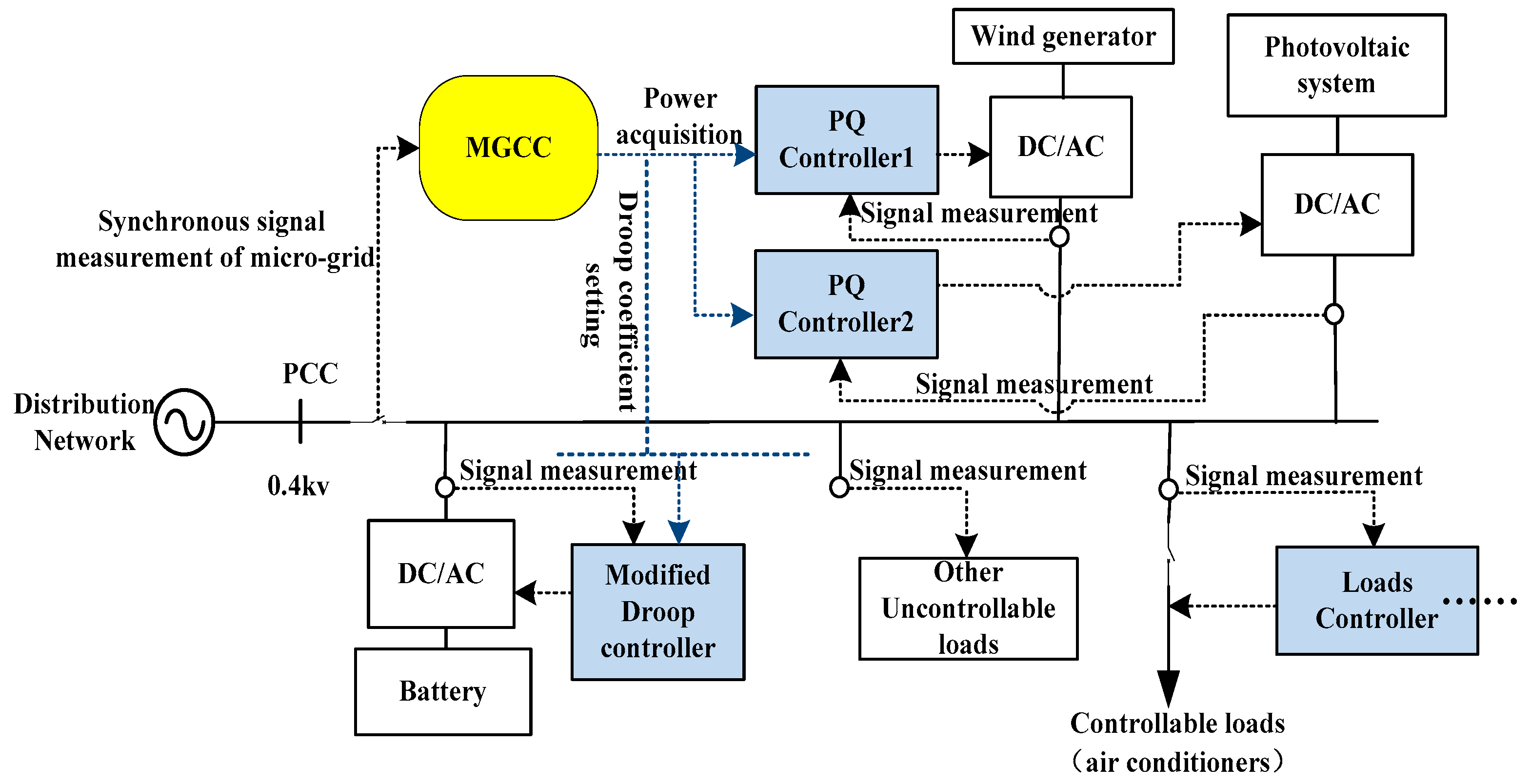
2. Isolated Micro-Grid System and Its Control Structure

This isolated micro-grid system consists of a photovoltaic system, a wind generator, a battery, uncontrollable loads and air conditioners as a representative of thermostatically controlled loads which can participate in micro-grid frequency regulation. Thermostatically controlled loads can provide limited frequency regulation capacity because they are restricted by temperature limits and start and stop interval times. Therefore, thermostatically controlled loads and the energy storage system are used to optimize the system frequency jointly based on the micro-grid hierarchical control structure in this paper. The hierarchical control configuration of micro-grid is shown in Figure 1.
In Figure 1, the distributed generator (DG) controllers and load controllers belong to local controllers, which all have the capability of primary frequency regulation. DG controllers and load controllers can control the response degree of the energy storage system and the switching state of the thermostatically controlled loads by the measurement signals of family intelligent measurement system obtaining control command of DG and thermostatically controlled loads. Thermostatically controlled loads take part in micro-grid operation control, which can effectively reduce the construction and use cost of the energy storage system. The micro-grid central controller (MGCC) has the capability of secondary frequency regulation, which uses the communication system to carry out real-time scheduling for micro-grid operation and focuses on eliminating the steady state error of the system frequency and voltage. After detecting the system frequency deviation signal, the MGCC utilizes the secondary frequency regulation strategy of the energy storage system to optimize primary frequency regulation result, which is achieved by thermostatically controlled loads and energy storage system.

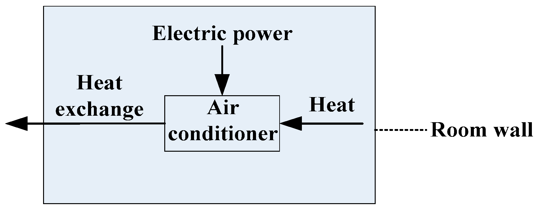
3. Thermostatically Controlled Load Model and Working Principle

Taking air conditioning as an example, its working process is that electric power is converted to thermal power to maintain the indoor temperature setting value and achieve heat exchange between outdoor temperature and indoor temperature as shown in Figure 2.
The working process of one air conditioner follows the energy conservation principle. Assuming that the energy loss is negligible during the power conversion and heat exchange, electric power is all converted into heat. The first order dynamic mathematical model of the working process for air conditioning is shown in Equations (1) and (2) according to the heat exchange principle [6].
C T ˙ i n ( t n ) = 1 R ( T e n ( t n ) T i n ( t n ) ) P N · s ( t n )
s ( t n + 1 ) = { 0 , T < T 1 , T > T + s ( t n ) ,   T < T < T +
where T i n ( t n ) is the indoor temperature, °C; T e n ( t n ) is the ambient temperature, °C; C is the specific heat capacity of the indoor wall; R is the thermal resistance of the indoor wall; s ( t n ) is the value of the air conditioner working state (1 or 0); P N is the rated power of the air conditioner, kW ; T + is the upper trigger temperature of the air conditioner, °C; T is the lower trigger temperature of air conditioner, °C.
From Equations (1) and (2), air conditioning temperature and power demand change over time in Figure 3. The air conditioner temperature T varies in a pre-set range [ T L , T H ]. Its working temperature is 26 degrees, and power demand is 1500 W. When the air conditioner is turned off, its temperature is 24 degrees, and power demand is 0 W.

4. Frequency Regulation Strategy of Loads

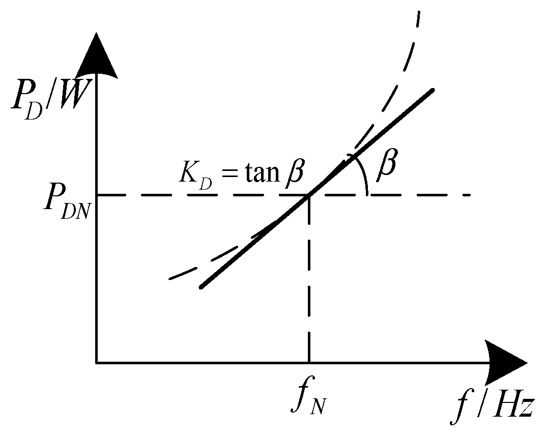
4.1. Frequency Regulation Strategy of Uncontrolled Loads

According to the proportion of loads in the power system, the relationship between the uncontrollable load power and system frequency is shown in Equation (3) [10].
P D = a 0 P D N + a 1 P D N ( f f N ) + a 2 P D N ( f f N ) 2 + a 3 P D N ( f f N ) 3 + · · ·
where P D is the active power of all uncontrollable loads at actual frequency f ; P D N is the active power of all uncontrollable loads at rated frequency f N ; a i is the percentage ( i = 0, 1, 2, …).
In the operation of the power system, permissible variation range of the system frequency is very small. The relationship between the frequency and power of uncontrollable loads shown above in Equation (3) is close to a straight line, which is shown in Figure 4.
In Figure 4, when the frequency decreases, the active power of the loads automatically reduces, and when the frequency increases, the active power of the loads automatically increases. This relationship is shown in Equation (4).
Δ P D = K D Δ f
where K D is the load frequency adjustment effect coefficient; Δ f is the system frequency offset; Δ P D is the load power variation which is caused by Δ f . K D is a calculation basis which is mastered by the scheduling department and used for load shedding. According to the value of K D , it can be determined that the power system needs the number of loads to restore the system frequency stability in the range of allowable frequency offset.

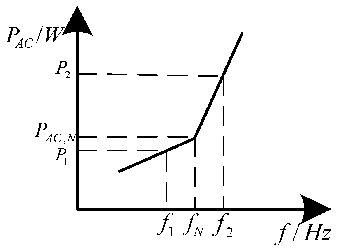
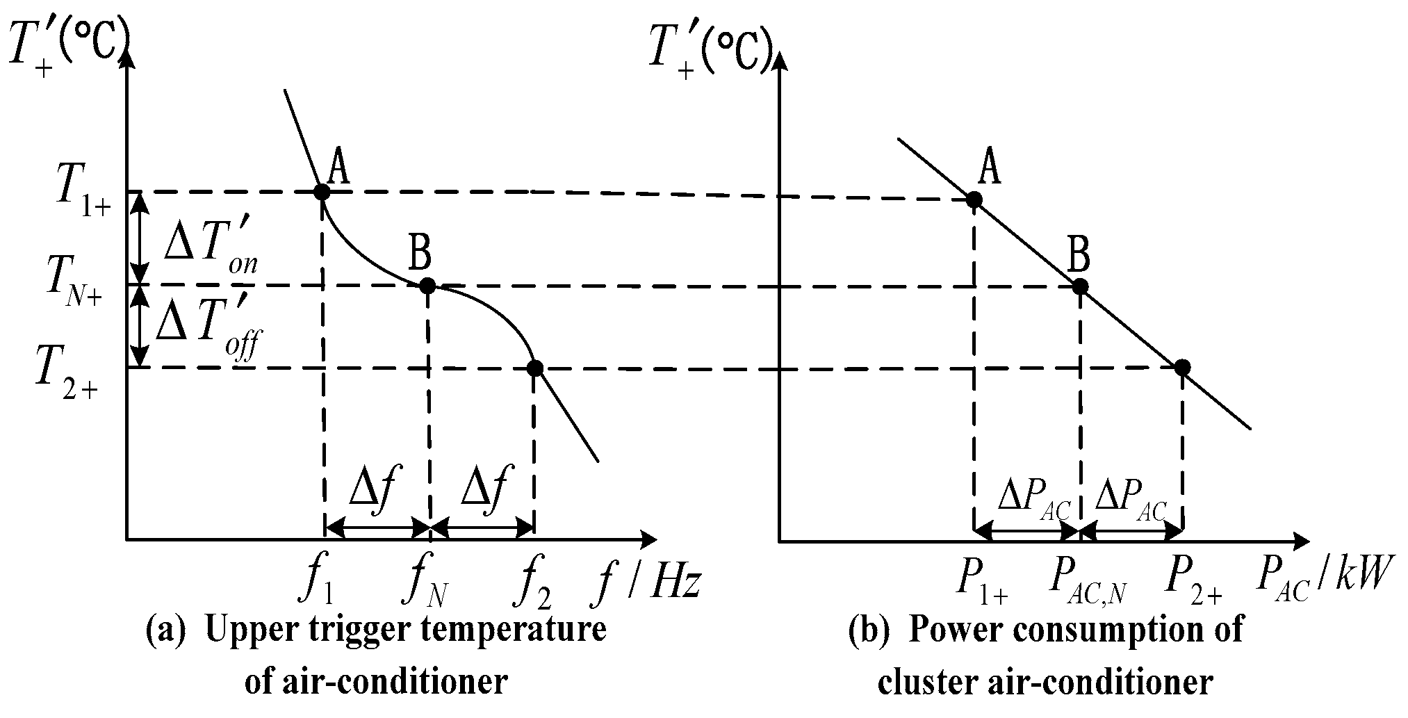
4.2. Frequency Regulation Strategy of Controlled Loads

Taking air conditioning as an example, based on the energy storage characteristics of air conditioning, the short-term adjustment of the air conditioning working status will not affect customer comfort. Thus, the cluster air conditioning can be like the generator to response frequency changes and participate in power grid frequency modulation.
According to the changes of micro-grid frequency, and considering customer comfort, short-term adjustment of the air conditioning trigger temperature setting value can make the working condition of air conditioning vary, change the power consumption of cluster air conditioning, and assist energy storage system to maintain the frequency of the micro-grid stable. This assumes that the change value of air conditioner trigger temperature is respectively Δ T o n , Δ T o f f when the system frequency is down and up, and the relationship between the change value of the trigger temperature and the frequency of the micro-grid is shown in Equations (5) and (6).
Δ T o n = p f o n | f f N |
Δ T o f f = p f o f f ( f f N )
where f is the actual frequency, Hz; f N is the rated frequency, 50 Hz; p f o n , p f o f f is the customer participation degree when the system frequency drops and increases, °C/Hz.
When cluster air conditioning is in a stable operation state and air conditioning temperature is in the uniform distribution in the [ T l , T h ] , the cluster air conditioning has a relatively stable power consumption. When the frequency of the micro-grid deviates from the rated frequency, the power variation of the cluster air conditioner is shown in Equation (7).
Δ P A C = { Δ T o n T + T · P N · N · o n % , ( T T + ) < Δ T < 0 Δ T o f f T + T · P N · N · o f f % , 0 Δ T < ( T + T )
where Δ P A C is the power variation of the air conditioners; P N is the rated power of air conditioner; N is the number of the cluster air conditioner; o n % ( o f f % ) is the percentage of air conditioners under state “on” (“off”).
Combined with Equations (5)–(7), the power change of the cluster air conditioning system has a linear relationship with the frequency of the micro-grid in Figure 5.
According to the primary frequency modulation characteristic of the generator, its frequency modulation strategy is shown in Equation (8).
Δ P G = K G Δ f
where Δ P G is the output power variation of the generator; Δ f is the system frequency variation; K G is the unit power regulation of the generator.
According to Equation (8), the frequency modulation characteristics of the cluster air conditioner with the system frequency dropping and increasing are all in accordance with the characteristics of primary frequency modulation of the generator. Considering customer comfort, when the decrement and increment of system frequency ( f N f 1 = f 2 f N ) are the same, the trigger temperature variation Δ T o n , Δ T o f f of air conditioning will be different, and the number of air conditioners participating in system frequency regulation will be different. Therefore, the power consumption Δ P A C ( P A C , N P 1 P 2 P A C , N ) of cluster air conditioning is different.
The micro-grid is composed of uncontrollable loads, cluster air conditioning and generating units. The frequency regulation effect of uncontrollable loads can generate a certain capacity. Cluster air conditioning with energy storage characteristics and a generating unit can also provide frequency regulation capacity for the micro-grid system. When uncontrollable loads, cluster air conditioning and generating units jointly maintain the micro-grid frequency stability, frequency modulation process is influenced by the number of air conditioning participated in frequency regulation which may cause micro-grid power imbalance again. In order to decrease the impact of the number of air conditioners participated in system frequency regulation on the micro-grid stability, it is needed to make the air conditioning frequency modulation process have nothing to do with the number of air-conditioning when the decreasing frequency value is same as the increasing frequency value. Air conditioner trigger temperature variations Δ T o n , Δ T o f f are required to reset in Equations (5) and (6) based on ensuring customer comfort and achieving maximum utilization of cluster air conditioning. The readjustment value of the air-conditioning trigger temperature is shown in Equations (9) and (10).
Δ T o n = p f o n N | f f N |
Δ T o f f = p f o f f N ( f f N ) · o n % o f f %
At this point, when the micro-grid frequency decreases and rises, the varied power value of cluster air conditioning is shown in Equation (11).
Δ P A C = P N o n % T + T · p f o n | f f N |
In Equation (11), we assume P N · o n % T + T p f o n = K A C .
According to the frequency modulation characteristic of the generator, K A C is defined as unit power regulation of the cluster air conditioning. p f o n is the customer participation degree after resetting the air conditioner trigger temperature. Adjusting the value of the user participation degree p f o n can give full play to the frequency modulation effect of the cluster air conditioning and meet the load demand of the micro-grid. When the decreasing frequency value is the same as the increasing frequency value, these two frequency modulation processes have nothing to do with the number of air conditioners involved. They will have the same output power.
Considering user comfort when the user is involved in frequency modulation, p f o n is designed as a linear function which is proportional to the frequency deviation of micro-grid in Equation (12).
p f o n = k f | f f N |
where k f is the customer participation coefficient; k f = 0 means the customers do not participate in frequency regulation.
Adjusting the user participation coefficient k f can indirectly adjust user participation degree. Thus, unit power regulation K A C of the cluster air conditioning is regulated, which makes the cluster air conditioning play a full role in the frequency regulation effect, thereby reducing frequency modulation output capacity of the generating unit.
Combining all of the above formulas, when the system frequency decreases, the trigger temperature of the air conditioning is increasing on the basis of its set value, and the frequency modulation strategy is shown in Equations (13) and (14).
T + = T + + 1 N k f ( f f N ) 2
T = T + 1 N k f ( f f N ) 2
When the system frequency rises, the trigger temperature of the air conditioning will reduce on the basis of its set value, and the frequency modulation strategy is shown in Equations (15) and (16).
T + = T + 1 N · o n % o f f % k f ( f f N ) 2
T = T 1 N · o n % o f f % k f ( f f N ) 2
From Equations (13)–(16), T + , T we respectively obtain maximum trigger temperature and minimum trigger temperature of air conditioning by readjusting.
Combining with Equations (7)–(11), (13) and (15), take T + as an example, the frequency response characteristics curve of cluster air conditioning involved in the frequency adjustment is shown in Figure 6.
From Figure 6 known, the values of T + and P A C are respectively T N + and P A C , N when the micro-grid frequency is rated frequency f N . And when the value of f m e a s decreases from f N to f 1 , the value of T + increases from T N + to T 1 + and the value of P A C decreases from P A C , N to P 1 + accordingly. Conversely, the value of P A C increases from P A C , N to P 2 + . When micro-grid frequency deviation ( f N f 1 = f 2 f N ) is the same, the variation Δ P A C of power consumption of cluster air conditioning is also the same. This means that the frequency modulation method for air conditioners completely adheres to the frequency response characteristic of the generator. Adjusting the unit power regulation K A C of the cluster air conditioning can meet the load demand of the micro-grid, which has nothing to do with the number of air conditioners involved and gives full play to the frequency modulation effect of cluster air conditioning to respond to the change of system frequency.

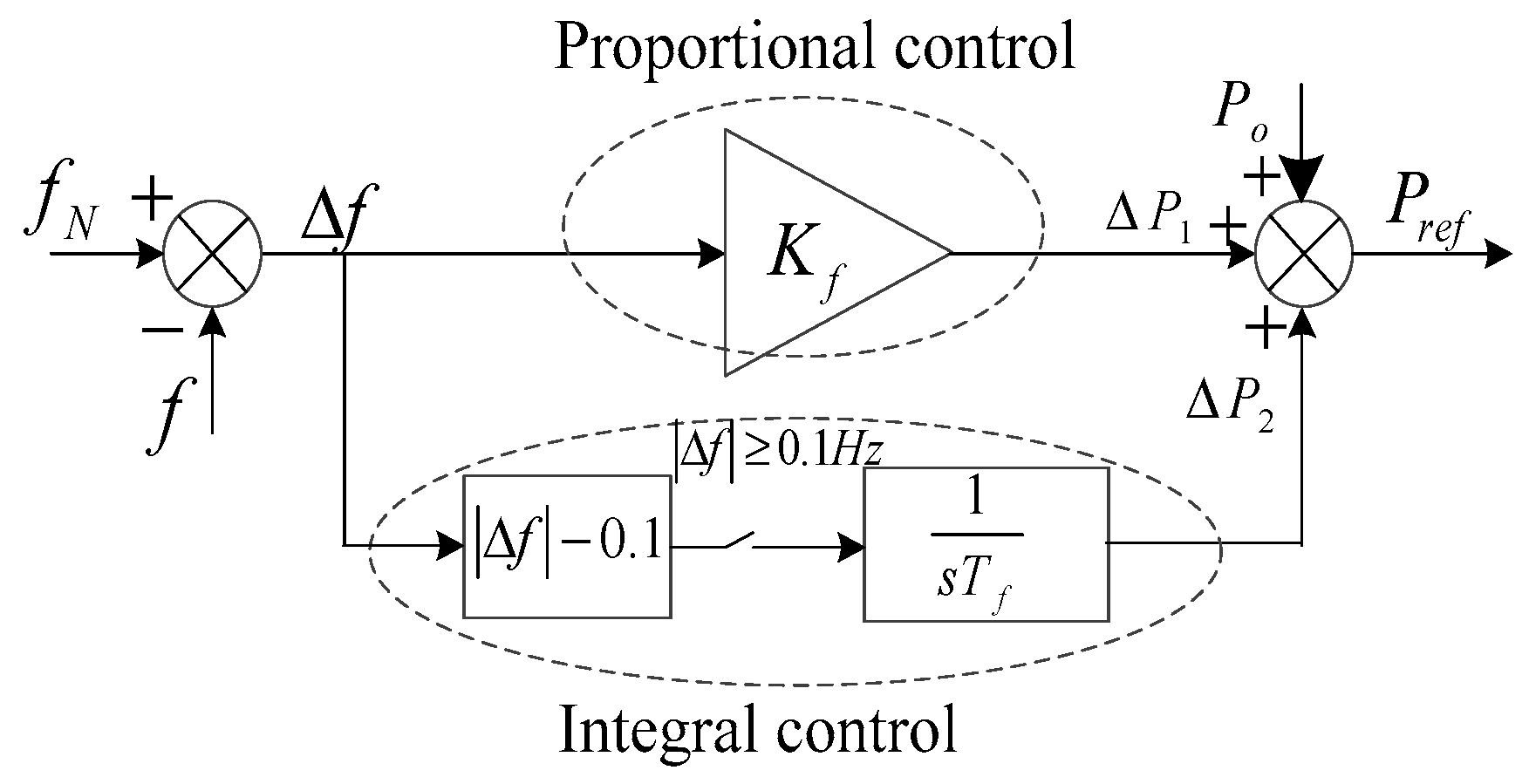
5. Frequency Modulation Strategy of Energy Storage System—Battery

The droop control characteristic of the battery [11], called proportional control, combines with the frequency modulation method of the cluster air conditioning, which can implement primary frequency regulation [12] for the micro-grid. The frequency modulation result will have the frequency offset. In order to reduce the system frequency offset, the battery is used to establish the secondary frequency regulation [13] for micro-grid. The method of realizing the secondary frequency modulation includes proportional control and integral control. In order to adjust the system frequency accurately, adding an integral part to the proportional control of battery can reduce the frequency deviation of the system, and realize the optimal regulation of the micro-grid frequency.
Based on integral-frequency modulation of the secondary frequency regulation method of the power system [14], the frequency modulation equation is shown in Formula (17).
Δ f d t + K Δ P G = 0
where Δ f the difference between the actual frequency f and the frequency reference value f N in the micro-grid; Δ P G is the power regulation value of the turbo-generator at the secondary frequency modulation; K is the proportional coefficient of the frequency modulation power.
From Equation (17), when Δ f is unequal to 0, Δ f d t accumulates constantly and Formula (17) cannot balance. When the frequency modulation process finishes, Δ f is equal to 0 and Δ f d t is a constant. The constant compensates system power shortage, which makes the system frequency recover to the rated value.
Referring to the integral-frequency modulation method of the power system and combining with the primary frequency modulation characteristics of cluster air conditioning, the inverse frequency modulation principle of battery is shown in Figure 7.
With the secondary frequency regulation of battery, the limit value of frequency offset Δ f is set 0.1 Hz. When the frequency offset Δ f is not less than 0.1 Hz, integral regulator works in Figure 7. The frequency offset of micro-grid is regulated optimally in the rage of 0.1 Hz. The integral-frequency modulation formula is shown in Equation (18).
P r e f = P o + Δ P 1 + Δ P 2 = P o + K f ( f N f ) + 1 s T f ( | f N f | 0.1 )
where Δ P 1 and Δ P 2 are respectively the different power regulation value in proportional control and integral control; P o is the initial output power of battery in a steady state; P r e f is the reference value of the current output power of battery in dynamic regulation process.
The proportional element and integral element are key parts of achieving frequency optimization for the MGCC in Figure 7. According to the droop coefficients produced by the MGCC, the current power output value of battery can be calculated to compensate for the system’s active power deficiency and optimize the frequency of the micro-grid by the deviation between the actual frequency and the rated frequency using the integral-frequency modulation characteristic.

6. Simulation Results

The micro-grid system consists of a photovoltaic system, wind generator, battery, uncontrollable loads and air conditioners as representative of thermostatically controlled loads. Taking air conditioning’s participation in system frequency regulation as an example, a 0.4 kv isolated micro-grid is built by using DIgSILENT software. The rated capacity and control method of each distributed generator is shown in Table 1. The simulation time is set to 200 min, and air conditioners participating in the frequency control of micro-grid have 400 units.

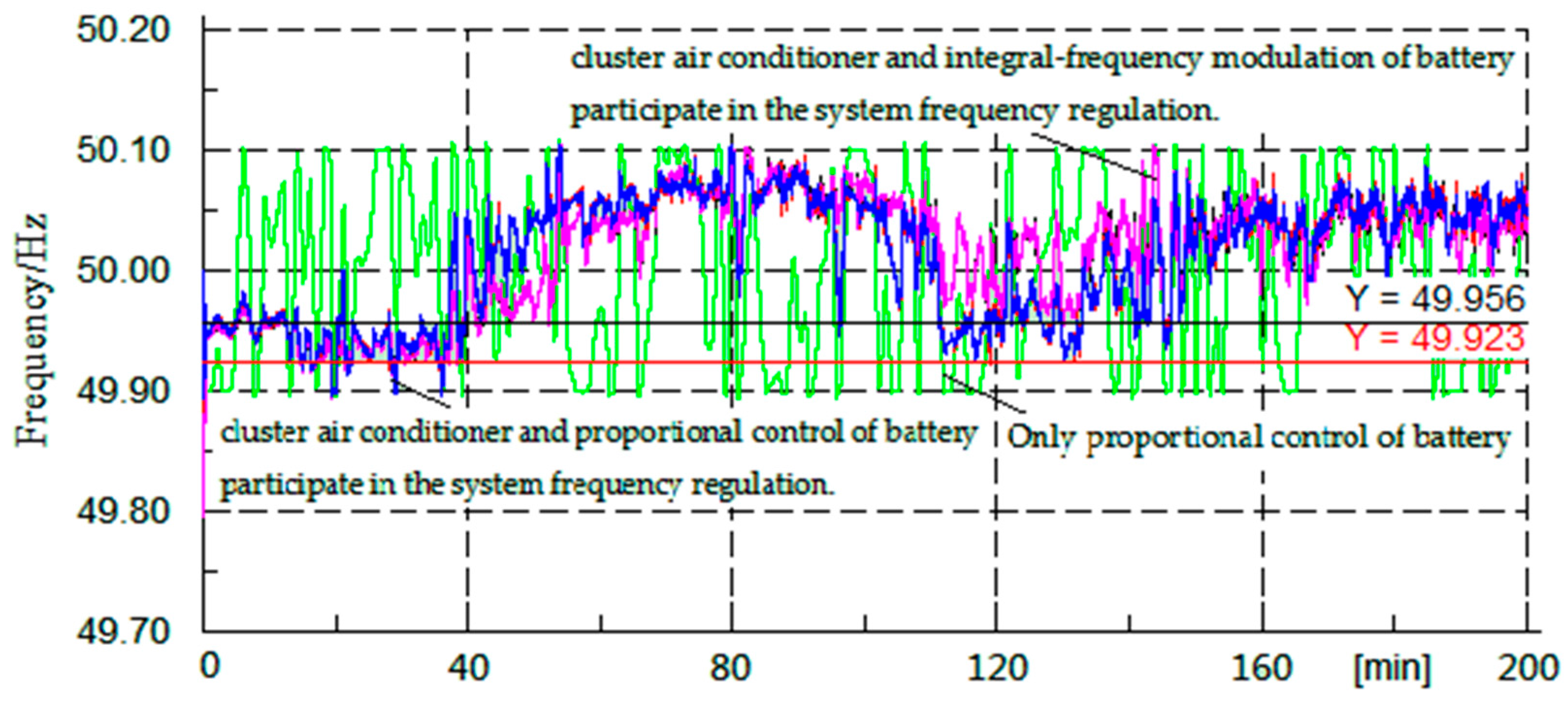
6.1. The Frequency Control Effect of the Micro-Grid by Maximizing Utilization of Cluster Air Conditioner

The frequency control effect is shown in Figure 8 by using cluster air conditioning and different battery frequency regulation methods. From Figure 8, it can be seen that the cluster air conditioner does not participate in the micro-grid frequency modulation, and only battery energy storage participates in frequency modulation; the frequency distribution range is [49.90 Hz, 50.10 Hz]. When cluster air conditioning is involved in primary frequency modulation of the micro-grid in coordination with the battery, the frequency is mainly distributed in [49.923 Hz, 50.10 Hz]. If cluster air conditioning and the battery are collaborative, which occurs in the secondary frequency adjustment of the micro-grid, the frequency range is [49.956 Hz, 50.10 Hz].
Based on the above, the rapid response characteristic of a cluster air conditioner is reflected, and when the cluster air conditioner takes part in micro-grid frequency regulation in coordination with different frequency modulation by the battery, micro-grid frequency fluctuation decreases gradually. The results of primary frequency modulation for the micro-grid can be optimized by cluster air conditioning and the integral-frequency modulation strategy of the battery which effectively improves the frequency control effect of the micro-grid.

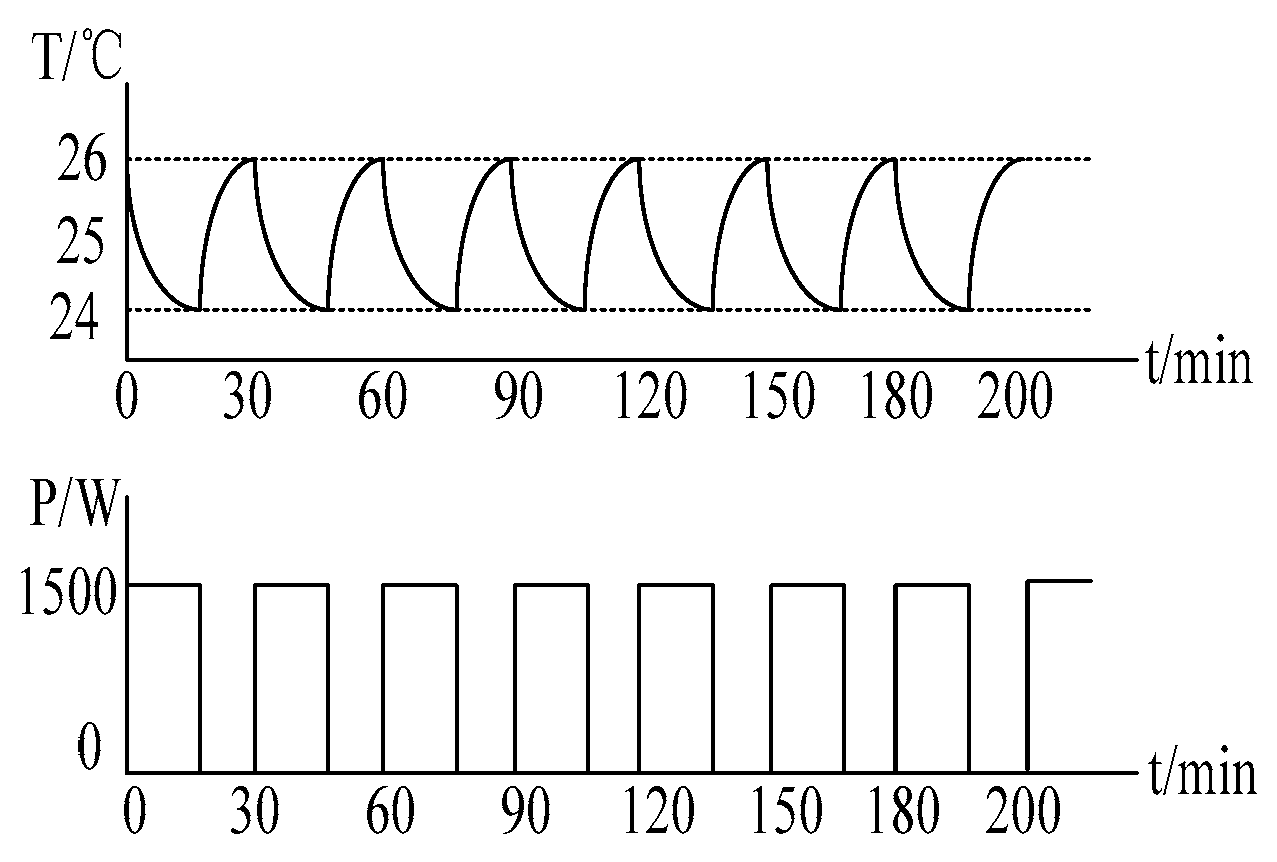
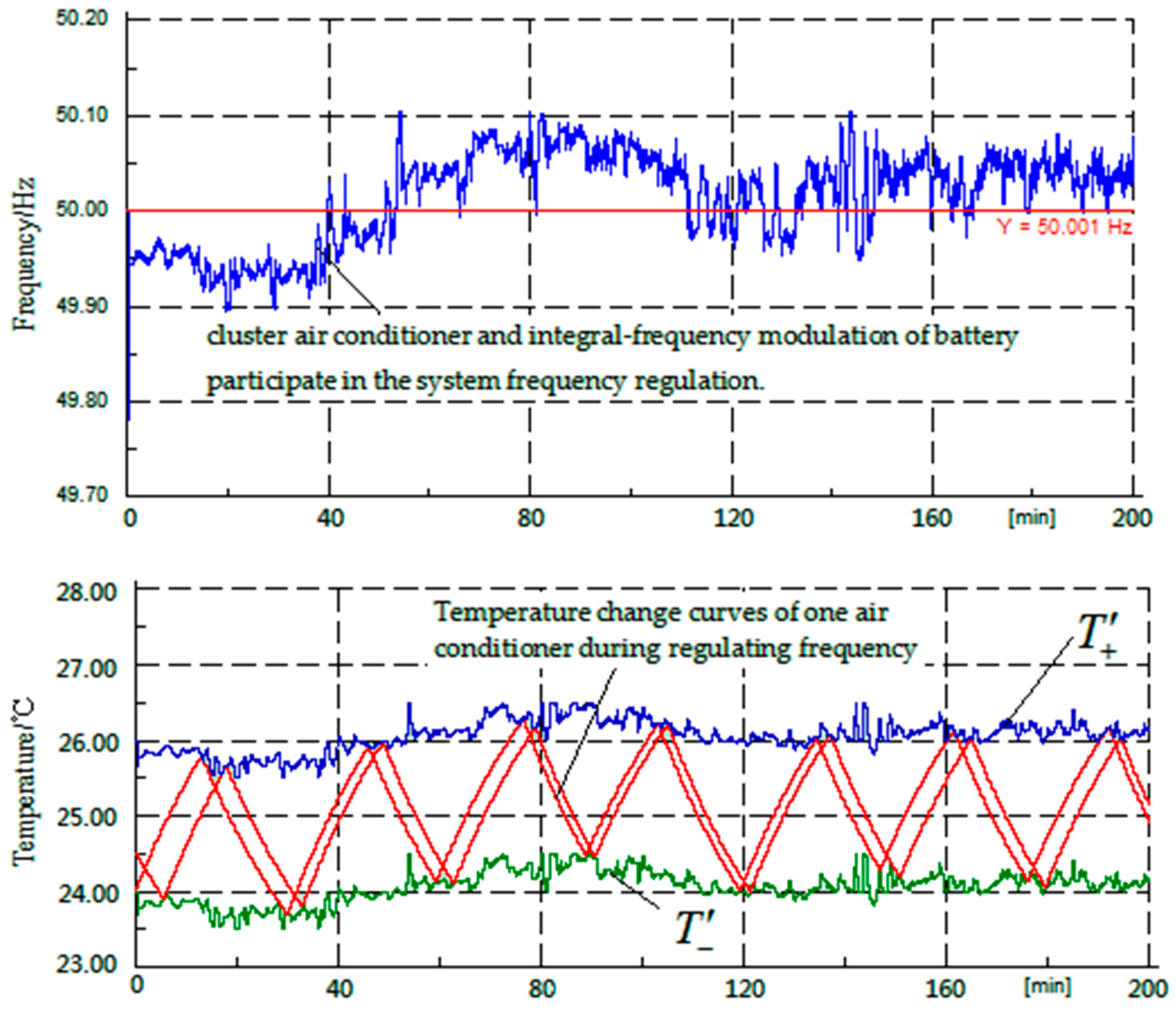
6.2. Dynamic Change of Air Conditioning Temperature with Frequency Fluctuation

The system frequency curve and temperature change curves of one air conditioner during the frequency regulation are shown at two different times in Figure 9, and they participate in micro-grid frequency control. In Figure 9 it can be seen that after the trigger temperatures T + and T are readjusted, their values dynamically change on the basis of the original trigger temperature (upper limit of 26 degrees, the lower limit of 24 degrees) with fluctuation of the micro-grid frequency. The working cycle of the air conditioning compressor also will be readjusted dynamically. When the micro-grid frequency is higher than 50 Hz, the values of T + and T rise and the starting time of the compressor is in advance. On the other hand, the compressor will be turned off ahead of time.

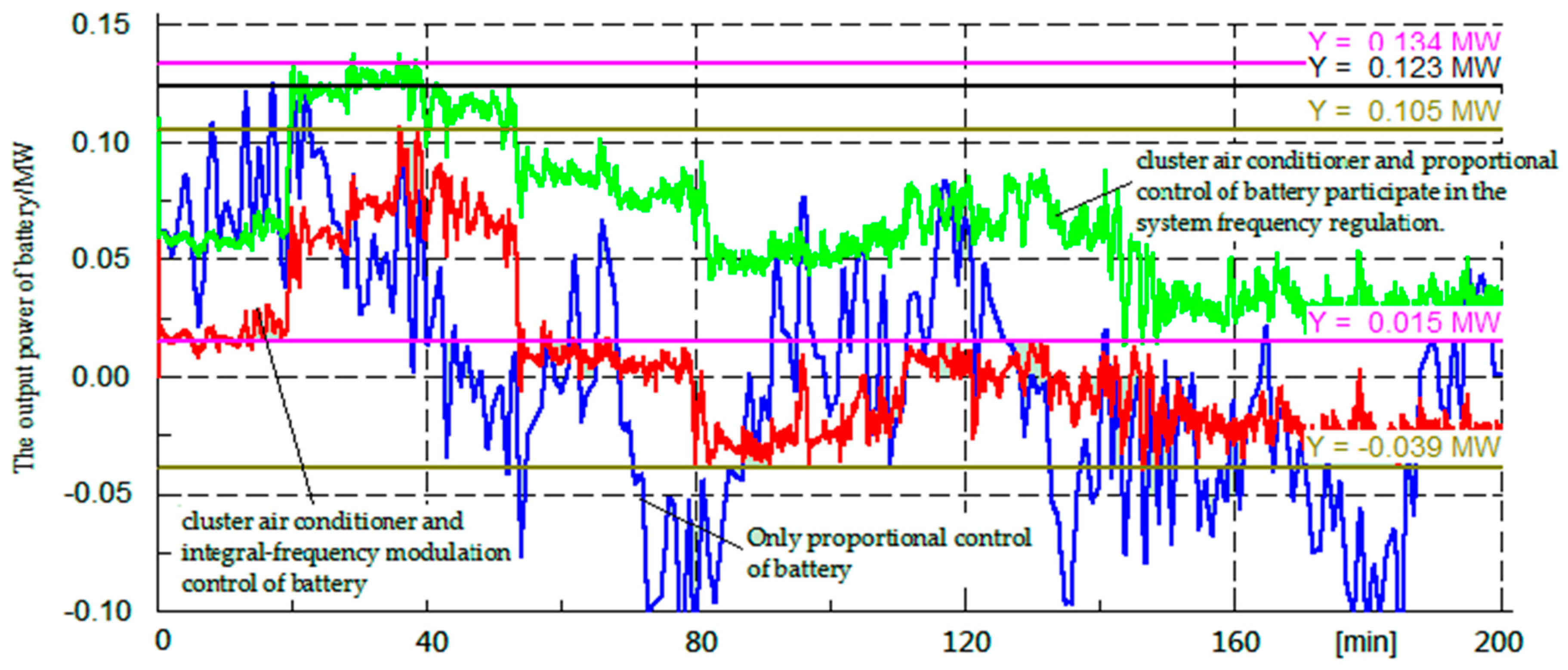
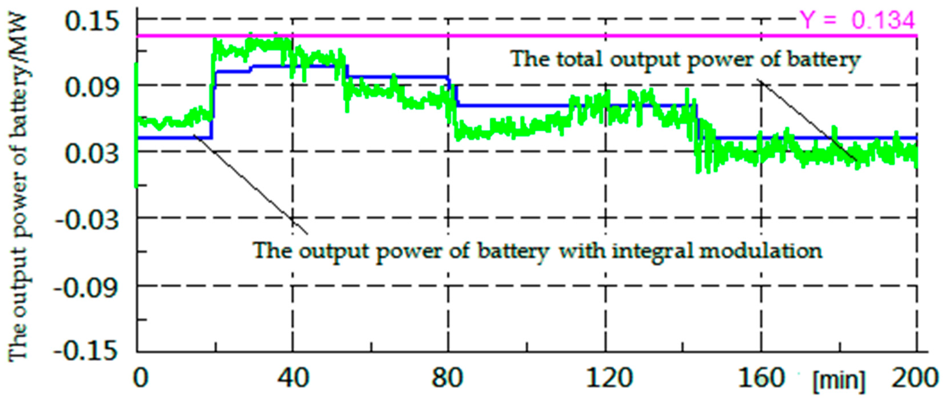
6.3. The Influence of Air Conditioning Frequency Modulation Method on the Output Power of the Battery

The output power curves of the battery are shown in Figure 10 and Figure 11 when the cluster air conditioning is in coordination with different frequency regulation methods of battery to adjust the system frequency. From Figure 10, it can be seen that the cluster air conditioner is not involved in micro-grid frequency modulation, and only battery energy storage participates in frequency modulation, as the output power range of the battery is [−0.10 MW, 0.123 MW]. The battery has been in a state of charge and discharge alternately. When cluster air conditioning participates in primary frequency modulation of the micro-grid in coordination with the battery, the output power of the battery is mainly distributed in [0.015 MW, 0.134 MW]. The battery has been in a state of discharge. If cluster air conditioning takes part in frequency adjustment of the micro-grid, which is in coordination with the integral-frequency modulation strategy of battery, the output power range of battery is [−0.039 MW, 0.105 MW]. The battery has been in a state of discharge for 0~80 min and the battery has been in a state of charge in 80~200 min. Thus, when the frequency regulation method of cluster air conditioner and integral-frequency modulation strategy of battery participate in frequency modulation, depth of charge and discharge for battery and the output power of battery are reducing. Based on Figure 11, little capacity of the battery is used and power shortage of the micro-grid is mainly compensated for by cluster air conditioner during the primary frequency regulation. Consequently, frequency modulation method for optimal utilization of cluster air conditioner participates in primary frequency regulation of micro-grid in coordination with the frequency control strategy of battery, which can effectively reduce the demand of capacity utilization for the battery, prolong its lifetime and cut down the construction costs of the micro-grid.
When the MGCC detects the system frequency fluctuation, the output power of primary frequency regulation and secondary frequency regulation for battery bear power shortage of the system by transmitting power adjustment instructions to the battery. The output power curve of the battery is shown during the secondary frequency modulation in Figure 11.
From Figure 11 it can be seen that the change trends of the total output power for the battery and the output power of the battery with integral modulation are the same. Therefore, this paper puts forward the frequency modulation method for cluster air conditioners which can take full advantage of the frequency modulation effect of cluster air conditioning, effectively reducing the capacity demand for the battery and extending its lifetime.

7. Conclusions

This paper presents a case study of air conditioning. It is proposed that the frequency modulation method of a cluster air conditioner can achieve optimal utilization of cluster air conditioning during the frequency regulation. Compared with the frequency modulation method which is achieved by cluster air conditioner and proportion control of the battery in Figure 6, a cluster air conditioner works in coordination with the battery’s integral-frequency modulation method in this paper, which can not only effectively improve the frequency control effect of micro-grid and optimize the system frequency, but give full play to the frequency modulation effect of the cluster air conditioner and reduce the capacity requirement of the energy storage system.

Acknowledgments

This work is supported by the Education Committee of Beijing basic research program of China (XN097) and Foundation of Collaborative Innovation Center of Key Power Energy-Saving Technologies in Beijing (PXM2016_014212_000016).

Author Contributions

Qingzhu Wan proposed the frequency control method and conducted the analysis. Yalan Chen analyzed the dates. Yuan Bian improved the frequency control method, validated it in simulations and wrote the paper.

Conflicts of Interest

The authors declare no conflicts of interest.

References

  1. Xin, J.; Wu, L. Hierarchical strategies for duty cycling control of air conditioners in business buildings. Autom. Electr. Power Syst. 2013, 37, 49–54. (In Chinese) [Google Scholar]
  2. Zhou, L.; Li, Y.; Gao, C. Improvement of Temperature Adjusting Method for Aggregated Air-conditioning Loads and Its Control Strategy. Proc. CSEE 2014, 34, 5579–5589. [Google Scholar]
  3. Zhang, Q.; Wang, X.; Wang, J.; Feng, C.; Liu, L. Survey of demand response research in deregulated electricity markets. Autom. Electr. Power Syst. 2008, 32, 97–106. (In Chinese) [Google Scholar]
  4. Yan, Q.; Hongjie, J.; Yunfei, M. Dynamic frequency control of autonomous microgrid based on family-friendly controllable loads. In Proceedings of the 2013 IEEE PES on Innovative Smart Grid Technologies (ISGT), Washington, DC, USA, 24–27 February 2013.
  5. Short, J.A.; Infield, D.G.; Freris, L.L. Stabilization of grid frequency through dynamic demand control. IEEE Trans. Power Syst. 2007, 22, 1284–1293. [Google Scholar] [CrossRef] [Green Version]
  6. Li, N.; Wang, X. Research of air conditioners providing frequency controlled reserve for microgrid. Power Syst. Prot. Control 2015, 43, 101–105. [Google Scholar]
  7. Jia, H.; Qi, Y.; Mu, Y. Frequency control method based on household temperature control load for isolated micro grid. Sci. China Sci. Technol. 2013, 43, 247–256. [Google Scholar]
  8. Khalid, E.; Luiz, A.C.L. Frequency based control of electric water heaters in small PV-Diesel hybrid MINI-Grids. In Proceedings of the 2012 25th IEEE Canadian Conference on Electrical & Computer Engineering (CCECE), Montreal, QC, Canada, 29 April–2 May 2012.
  9. Xu, Z.; Østergaard, J.; Togeby, M. Design and modelling of thermostatically controlled loads as frequency controlled reserve. In Proceedings of the 2007 IEEE Power Engineering Society General Meeting, Tampa, FL, USA, 24–28 June 2007.
  10. Fang, J.; Huang, L.; Ji, J.; Sun, G. Power Systems Analysis; China Water & Power Press: Beijing, China, 2007. [Google Scholar]
  11. Li, H.; Wang, Y.; Zhang, L.; Liu, J. Frequency Coordination Control Strategy for Microgrid in Islanded Operation. Electr. Power Sci. Eng. 2012, 28, 56–62. [Google Scholar]
  12. Tang, Y.; Deng, K.; Sun, H.; Yi, J.; He, Q. Research on Coordination Scheme for Smart Household Appliances Participating Under frequency Load Shedding. Power Syst. Technol. 2013, 37, 2861–2867. [Google Scholar]
  13. Wang, J.; Chen, M.; Wen, L.; Wen, F.; Zhang, K.; Zhang, K. New index for frequency quality evaluation in power systems. J. North China Electr. Power Univ. 2010, 37, 7–13. [Google Scholar]
  14. Wang, K.; Sun, Y. Automation of Electric Power Systems; Electric Power Press of China: Beijing, China, 2007. [Google Scholar]
Figure 1. The hierarchical control structure of an isolated micro-grid.
Energies 09 01085 g001
Figure 2. Heat exchange process for one air conditioner.
Energies 09 01085 g002
Figure 3. Power demand and temperature changes during air-conditioning operation.
Energies 09 01085 g003
Figure 4. Frequency characteristic curve of loads.
Energies 09 01085 g004
Figure 5. Frequency characteristic of cluster air conditioner.
Energies 09 01085 g005
Figure 6. Frequency response characteristics of the cluster air conditioner.
Energies 09 01085 g006
Figure 7. Integral-frequency modulation control diagram.
Energies 09 01085 g007
Figure 8. The system frequency curves with different frequency regulation methods of battery.
Energies 09 01085 g008
Figure 9. The system frequency curve and the temperature change curves of one air conditioner during the frequency regulation.
Energies 09 01085 g009
Figure 10. The power curves of battery with different frequency regulation methods.
Energies 09 01085 g010
Figure 11. The output power curve of the battery.
Energies 09 01085 g011
Table 1. Capacity and control method of DG.
DG TypeDG NameCapacity (MW)Control Mode
Intermittent DGsWind generator0.06PQ control
Photovoltaic system0.4PQ control
ESSBattery1.0Integral-frequency modulation control

