
Modeling of a Field-Modulated Permanent-Magnet Machine


Abstract
:1. Introduction
2. Topology and Operating Principle
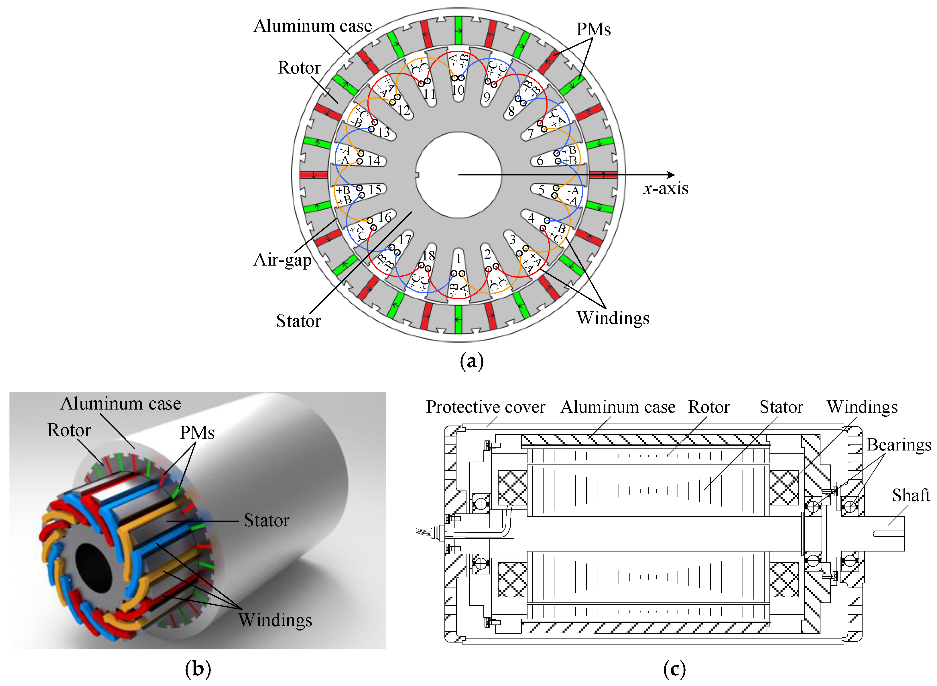
2.1. Topology
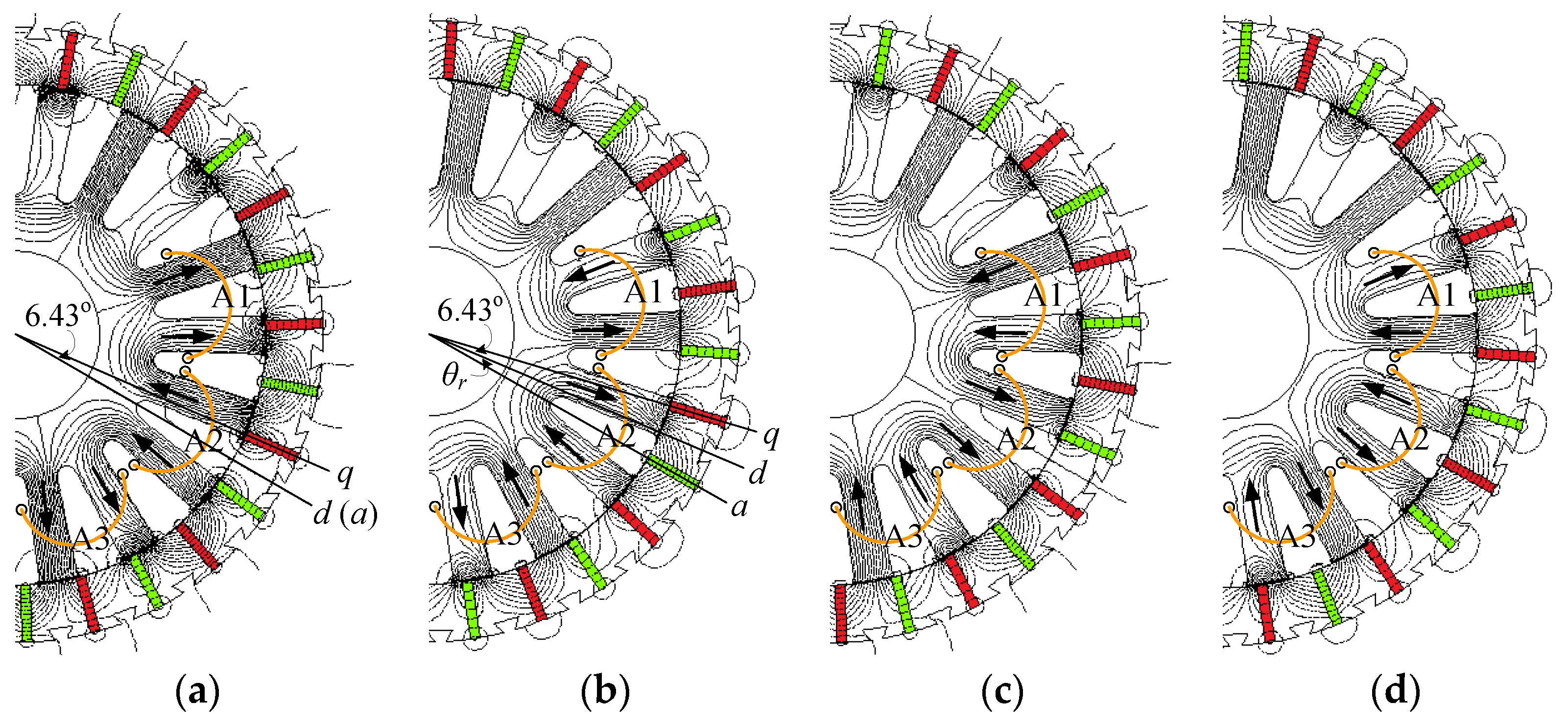
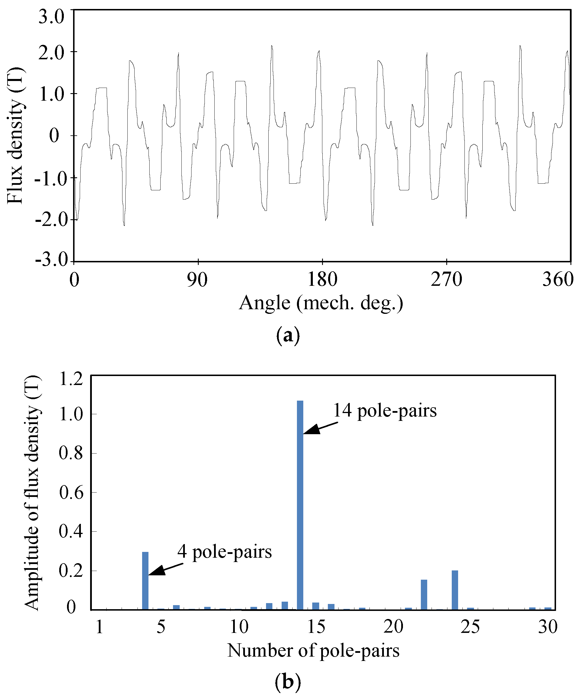
2.2. Operating Principle
3. Mathematical Modeling
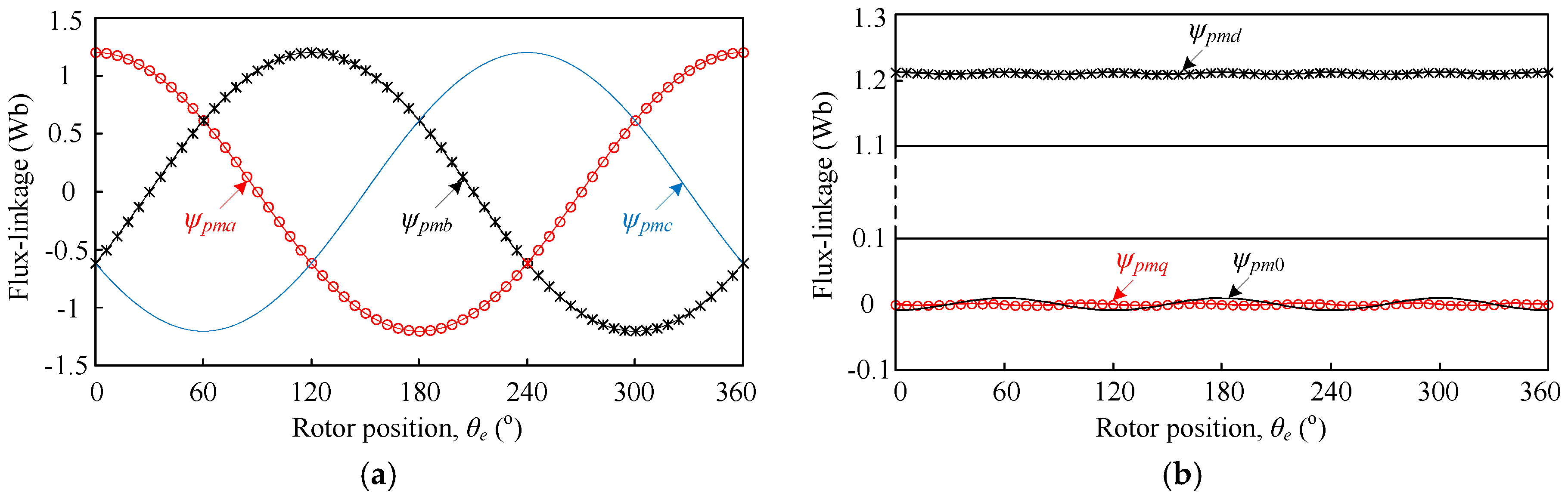
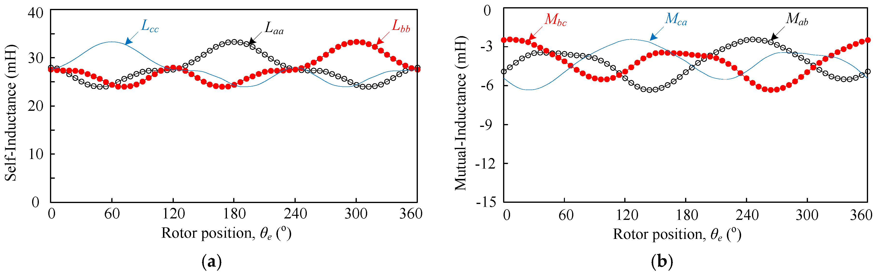
3.1. Mathematical Model in Stator Reference Frame
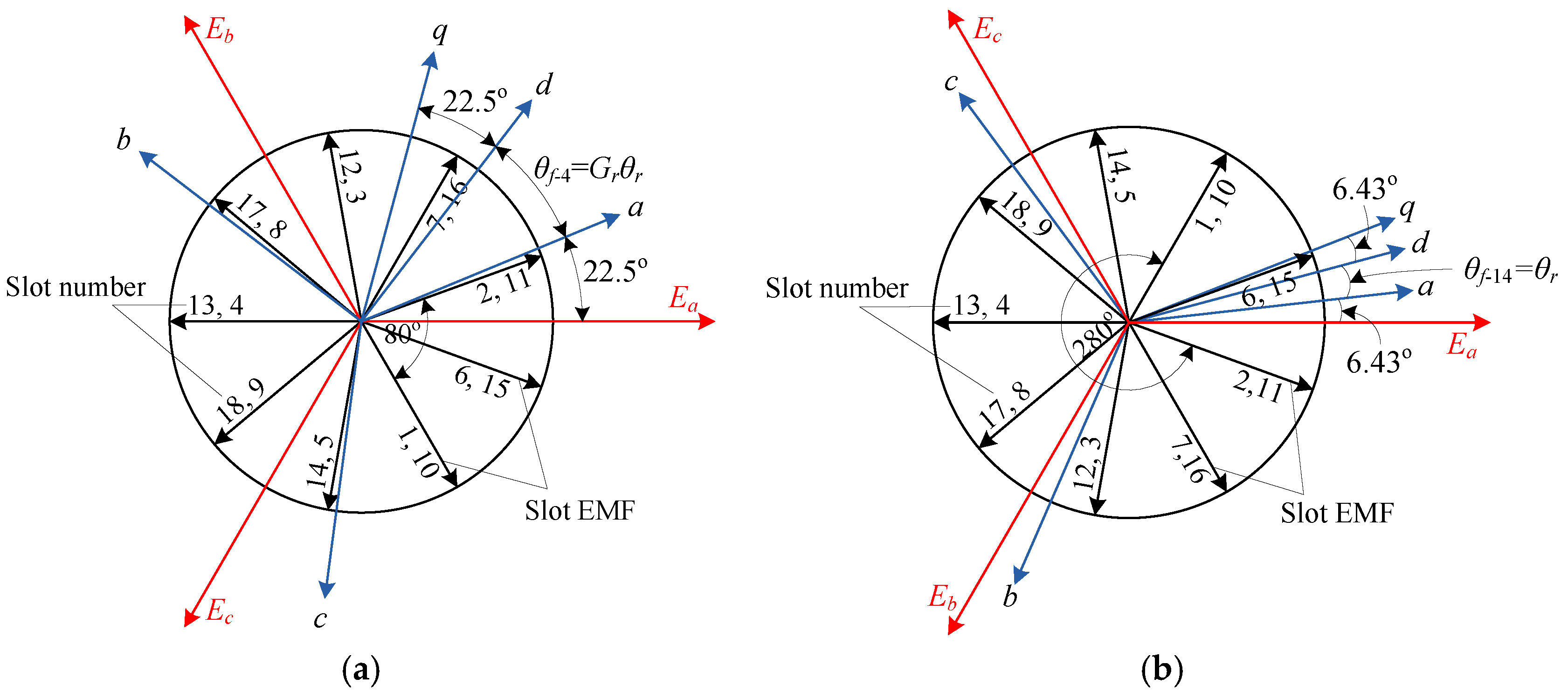
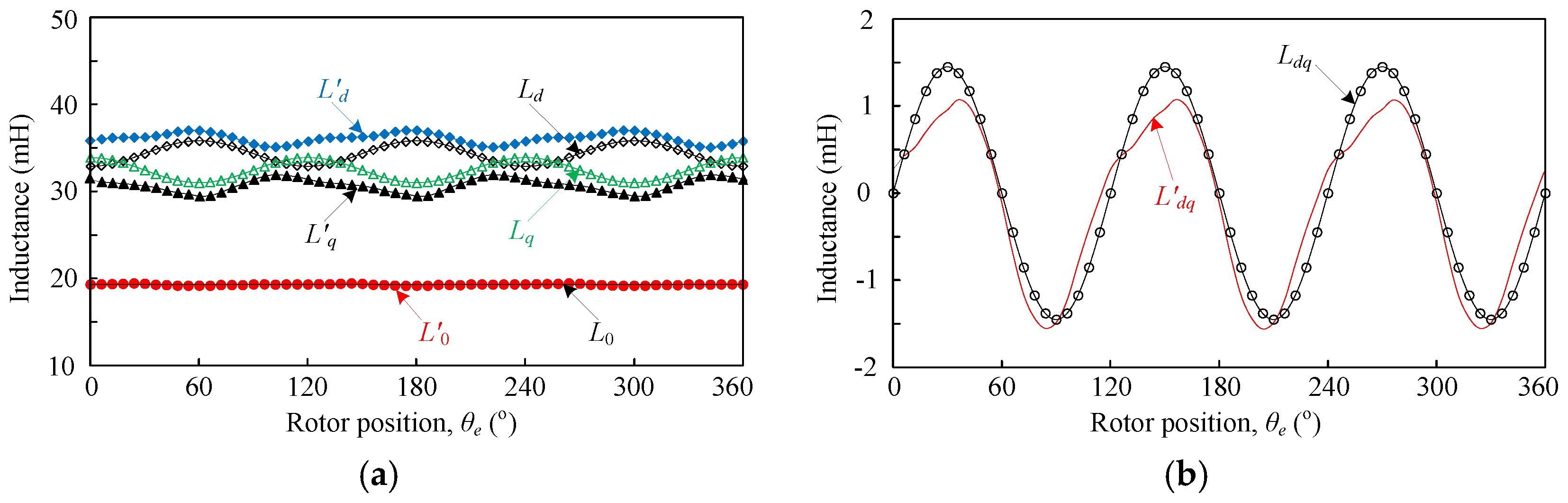
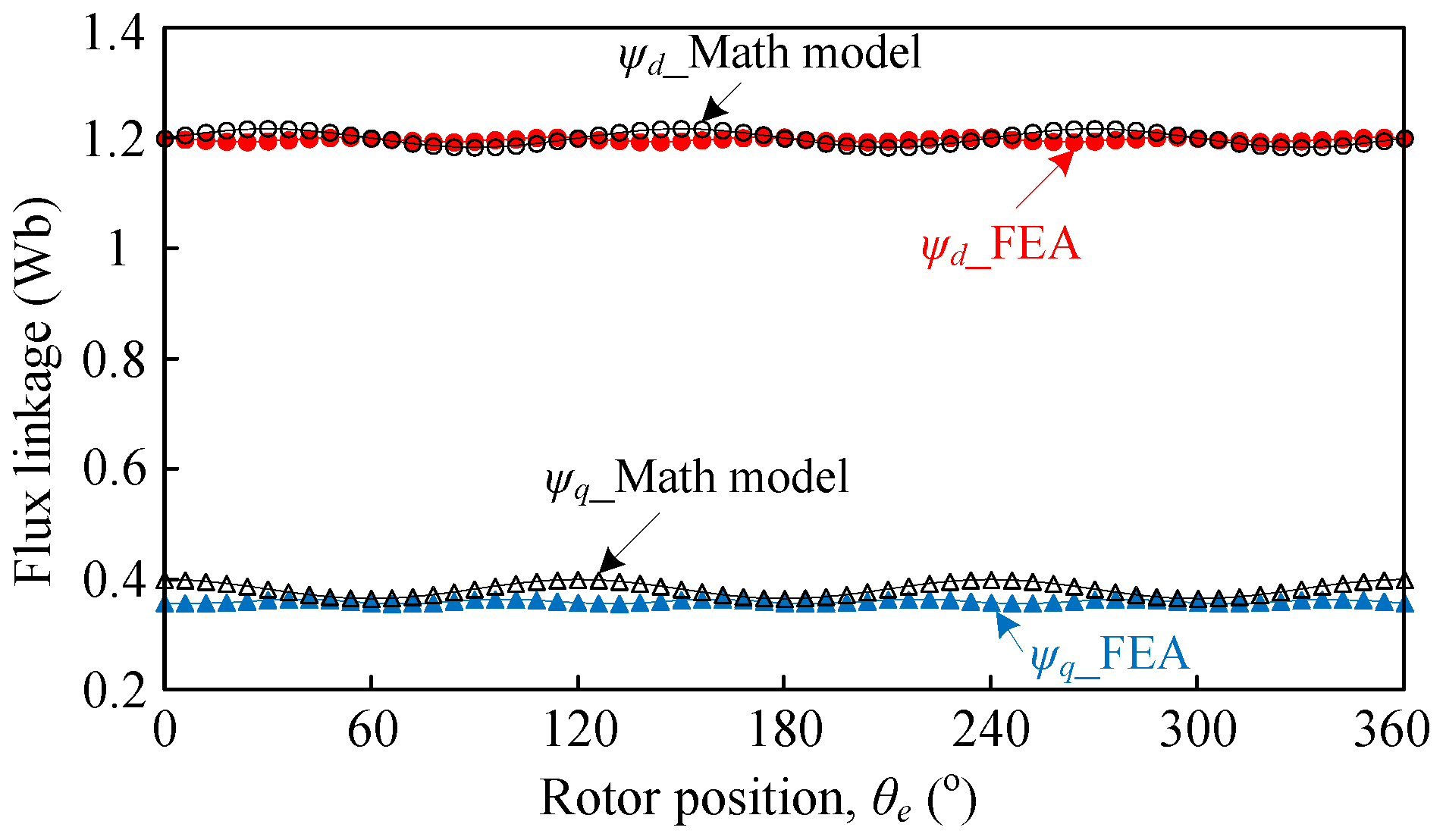
3.2. Abc-dq Transformation
3.3. Electromagnetic Torque
4. Experimental Results
5. Conclusions
Acknowledgments
Author Contributions
Conflicts of Interest
References
- Toba, A.; Lipo, T.A. Generic torque-maximizing design methodology of surface permanent-magnet vernier machine. IEEE Trans. Ind. Appl. 2000, 36, 1539–1546. [Google Scholar]
- Atallah, K.; Calverley, S.D.; Howe, D. Design, analysis and realization of a high-performance magnetic gear. IEE Proc. Electr. Power Appl. 2004, 151, 135–143. [Google Scholar] [CrossRef]
- Niu, S.X.; Ho, S.L.; Fu, W.N.; Wang, L.L. Quantitative comparison of novel vernier permanent magnet machines. IEEE Trans. Magn. 2010, 46, 2032–2035. [Google Scholar] [CrossRef]
- Vukotić, M.; Miljavec, D. Design of a permanent-magnet flux-modulated machine with a high torque density and high power factor. IET Electr. Power Appl. 2016, 10, 36–44. [Google Scholar] [CrossRef]
- Zheng, P.; Song, Z.Y.; Bai, J.G.; Tong, C.D.; Yu, B. Research on an axial magnetic-field-modulated brushless double rotor machine. Energies 2013, 6, 4799–4829. [Google Scholar] [CrossRef]
- Luo, X.; Niu, S.X. Maximum power point tracking sensorless control of an axial-flux permanent magnet vernier wind power generator. Energies 2016, 9, 581. [Google Scholar] [CrossRef]
- Du, Y.; Cheng, M.; Chau, K.T.; Liu, X.; Xiao, F.; Zhao, W. Linear primary permanent magnet vernier machine for wave energy conversion. IET Electr. Power Appl. 2015, 9, 203–212. [Google Scholar] [CrossRef]
- Cheng, M.; Sun, L.; Buja, G.; Song, L. Advanced electrical machines and machine-based systems for electric and hybrid vehicles. Energies 2015, 8, 9541–9564. [Google Scholar] [CrossRef]
- Cheng, M.; Zhu, Y. The state of the art of wind energy conversion systems and technologies: A review. Energy Convers. Manag. 2014, 88, 332–347. [Google Scholar] [CrossRef]
- Wang, Q.; Niu, S.X.; Ho, S.L.; Fu, W.N.; Zuo, S. Design and analysis of novel magnetic flux-modulated mnemonic machines. IET Electr. Power Appl. 2015, 9, 469–477. [Google Scholar] [CrossRef]
- Li, D.W.; Qu, R.H.; Lipo, T.A. High-power-factor vernier permanent magnet machines. IEEE Trans. Ind. Appl. 2014, 50, 3664–3674. [Google Scholar] [CrossRef]
- Jian, L.N.; Xu, G.Q.; Mi, C.C.; Chau, K.T.; Chan, C.C. Analytical method for magnetic field calculation in a low-speed permanent-magnet harmonic machine. IEEE Trans. Energy Convers. 2011, 26, 862–870. [Google Scholar] [CrossRef] [Green Version]
- Li, X.L.; Chau, K.T.; Cheng, M.; Kim, B.; Lorenz, R.D. Performance analysis of a flux-concentrating field-modulated permanent-magnet machine for direct-drive applications. IEEE Trans. Magn. 2015, 51. [Google Scholar] [CrossRef]
- Shao, L.Y.; Hua, W.; Dai, N.Y.; Tong, M.H.; Cheng, M. Mathematical modeling of a 12-phase flux-switching permanent-magnet machine for wind power generation. IEEE Trans. Ind. Electron. 2016, 63, 504–516. [Google Scholar] [CrossRef]
- Li, X.L.; Chau, K.T.; Cheng, M. Analysis, design and experimental verification of a field-modulated permanent-magnet machine for direct-drive wind turbines. IET Electr. Power Appl. 2015, 9, 150–159. [Google Scholar] [CrossRef]
- Wu, L.L.; Qu, R.H.; Li, D.W.; Gao, Y.T. Influence of pole ratio and winding pole numbers on performance and optimal design parameters of surface permanent-magnet vernier machines. IEEE Trans. Ind. Appl. 2015, 51, 3707–3715. [Google Scholar] [CrossRef]
- Kim, B.; Lipo, T.A. Operation and design principles of a PM vernier motor. IEEE Trans. Ind. Appl. 2014, 50, 3656–3663. [Google Scholar] [CrossRef]
- Krishnan, R. Permanent Magnet Synchronous and Brushless DC Motor Devices; CRC Press: Boca Raton, FL, USA, 2010. [Google Scholar]
- Kim, S.; Lee, G.H.; Hong, J.P.; Jung, T.U. Design process of interior PM synchronous motor for 42-V electric air-conditioner system in hybrid electric vehicle. IEEE Trans. Magn. 2008, 44, 1590–1593. [Google Scholar]
- Li, D.W.; Qu, R.H.; Xu, W.; Li, J.; Lipo, T.A. Design procedure of dual-stator spoke-array vernier permanent-magnet machines. IEEE Trans. Ind. Appl. 2015, 51, 2972–2983. [Google Scholar] [CrossRef]

 ” represents the direction of flux line). (a) θe = 0°; (b) θe = 90°; (c) θe = 180°; and (d) θe = 270°.
” represents the direction of flux line). (a) θe = 0°; (b) θe = 90°; (c) θe = 180°; and (d) θe = 270°.
” represents the direction of flux line). (a) θe = 0°; (b) θe = 90°; (c) θe = 180°; and (d) θe = 270°.


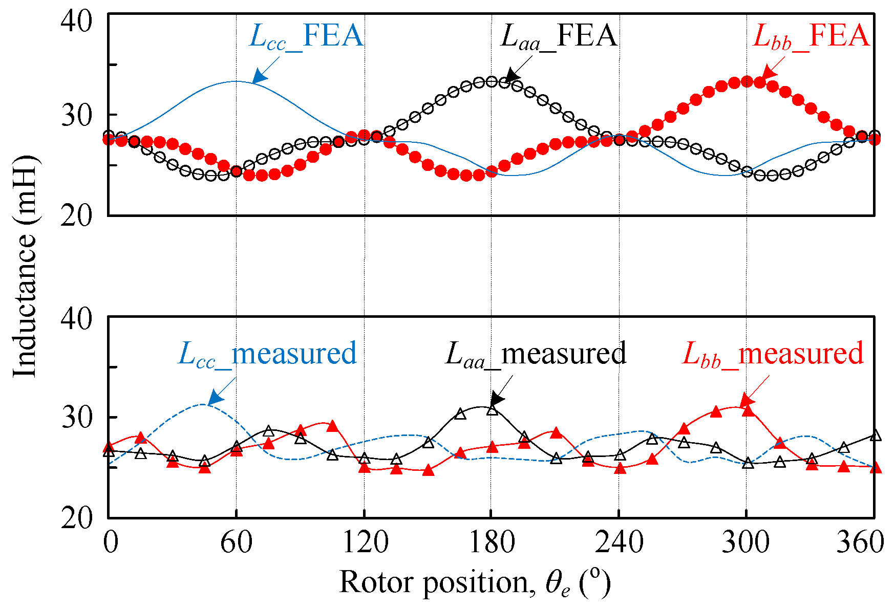
| Items | Self-Inductance | Mutual Inductance | ||
|---|---|---|---|---|
| Peak Value (mH) | Phase Angle | Peak Value (mH) | Phase Angle | |
| DC component | 28.711 | - | −4.7168 | - |
| First harmonic | 2.9022 | 2.9° | 0.8127 | −76.5° |
| Second harmonic | 1.9161 | 6° | 1.353 | −51.1° |
| Third harmonic | 0.2063 | 9.3° | 0.03 | −72.7° |
| Fourth harmonic | 1.2522 | 11.8° | 0.289 | 71.3° |
| Fifth harmonic | 0.0784 | 13.6° | 0.1454 | −13.4° |
| Items | Flux Linkage (Wb) | |
|---|---|---|
| From FEA | From Math Model | |
| ψpmd | 1.2106 | 1.2031 |
| ψpmq | −0.000079 | 0 |
| ψpm0 | −0.000173 | 0 |
| Items | Average Values of Inductance (mH) | ||
|---|---|---|---|
| From FEA | From Math Model | From [19] | |
| L’d (Ld) | 35.35 | 34.33 | 33.68 |
| L’q (Lq) | 31.58 | 32.47 | 30.72 |
| L’0 (L0) | 19.3 | 19.3 | - |
| L’dq (Ldq) | −0.094 | 0 | - |
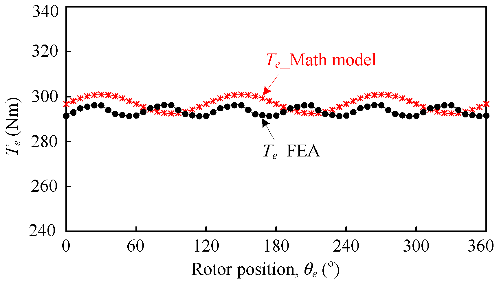
| Items | Te_Math Model | Te_FEA |
|---|---|---|
| Temax (Nm) | 301.8 | 296.1 |
| Temin (Nm) | 293.4 | 291.1 |
| Teavg (Nm) | 297.6 | 293.4 |
| Kripple (%) | 2.8 | 1.7 |
| Parameters | Values | Parameters | Values |
|---|---|---|---|
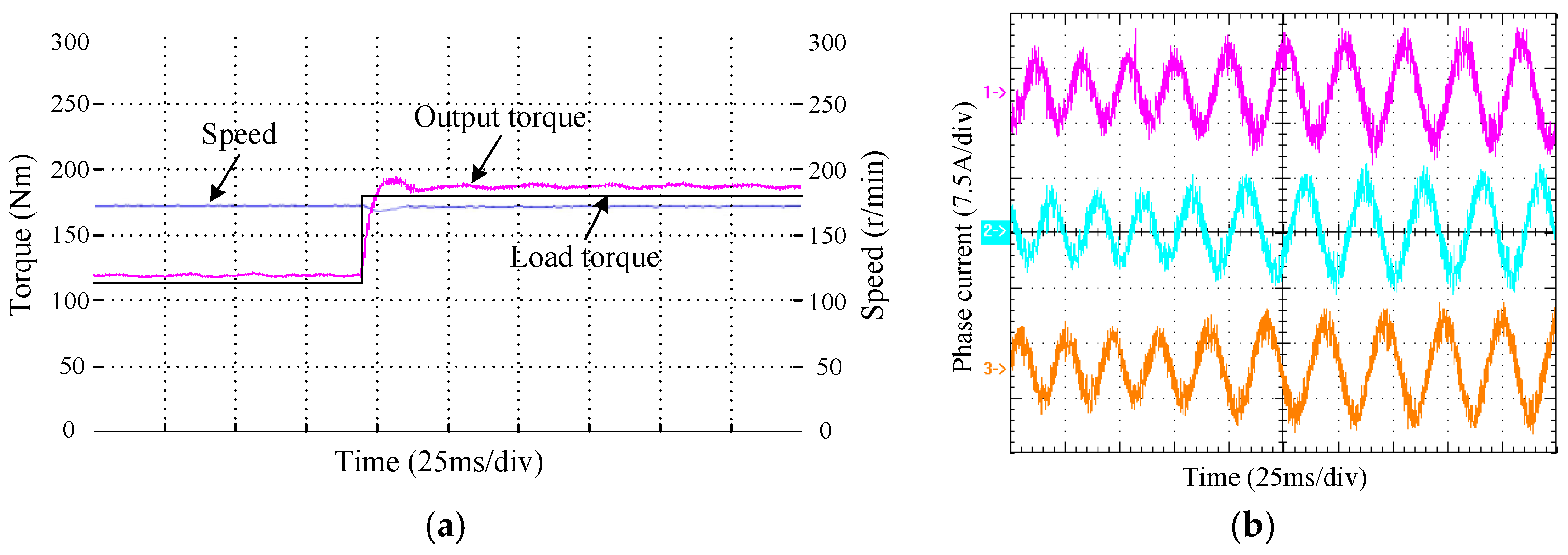
| Rated speed (r/min) | 172 | Outer diameter of rotor (mm) | 220 |
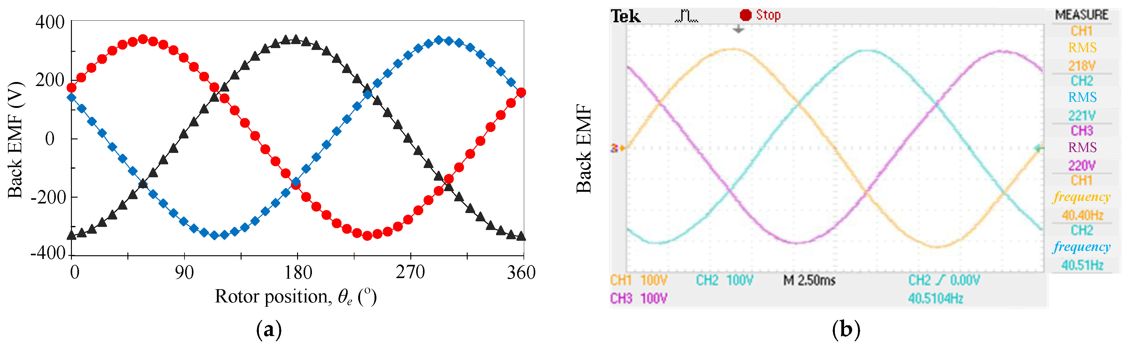
| Back-EMF (V) | 220 | Inner diameter of stator (mm) | 60 |
| Rated current (A) | 8.3 | Air-gap length (mm) | 0.5 |
| No. of rotor pole-pairs | 14 | Stack length (mm) | 300 |
| No. of stator teeth | 18 | Iron lamination material | DW470 |
| No. of stator pole-pairs | 4 | PM material | N38SH |
© 2016 by the authors; licensee MDPI, Basel, Switzerland. This article is an open access article distributed under the terms and conditions of the Creative Commons Attribution (CC-BY) license (http://creativecommons.org/licenses/by/4.0/).
Share and Cite
Li, X.; Chau, K.T.; Wang, Y. Modeling of a Field-Modulated Permanent-Magnet Machine. Energies 2016, 9, 1078. https://doi.org/10.3390/en9121078
Li X, Chau KT, Wang Y. Modeling of a Field-Modulated Permanent-Magnet Machine. Energies. 2016; 9(12):1078. https://doi.org/10.3390/en9121078
Chicago/Turabian StyleLi, Xianglin, K. T. Chau, and Yubin Wang. 2016. "Modeling of a Field-Modulated Permanent-Magnet Machine" Energies 9, no. 12: 1078. https://doi.org/10.3390/en9121078