
Simplified V/f Control Algorithm for Reduction of Current Fluctuations in Variable-Speed Operation of Induction Motors

Abstract
:1. Introduction
2. Control Strategy
2.1. Dynamic Equations of the Stator Current of an Induction Motor
2.2. Proposed Control for Current Fluctuation Suppression
2.3. Relationship between Rotor Moment of Inertia and Electromagnetic Torque of Induction Motor
3. Proposed Control Verification
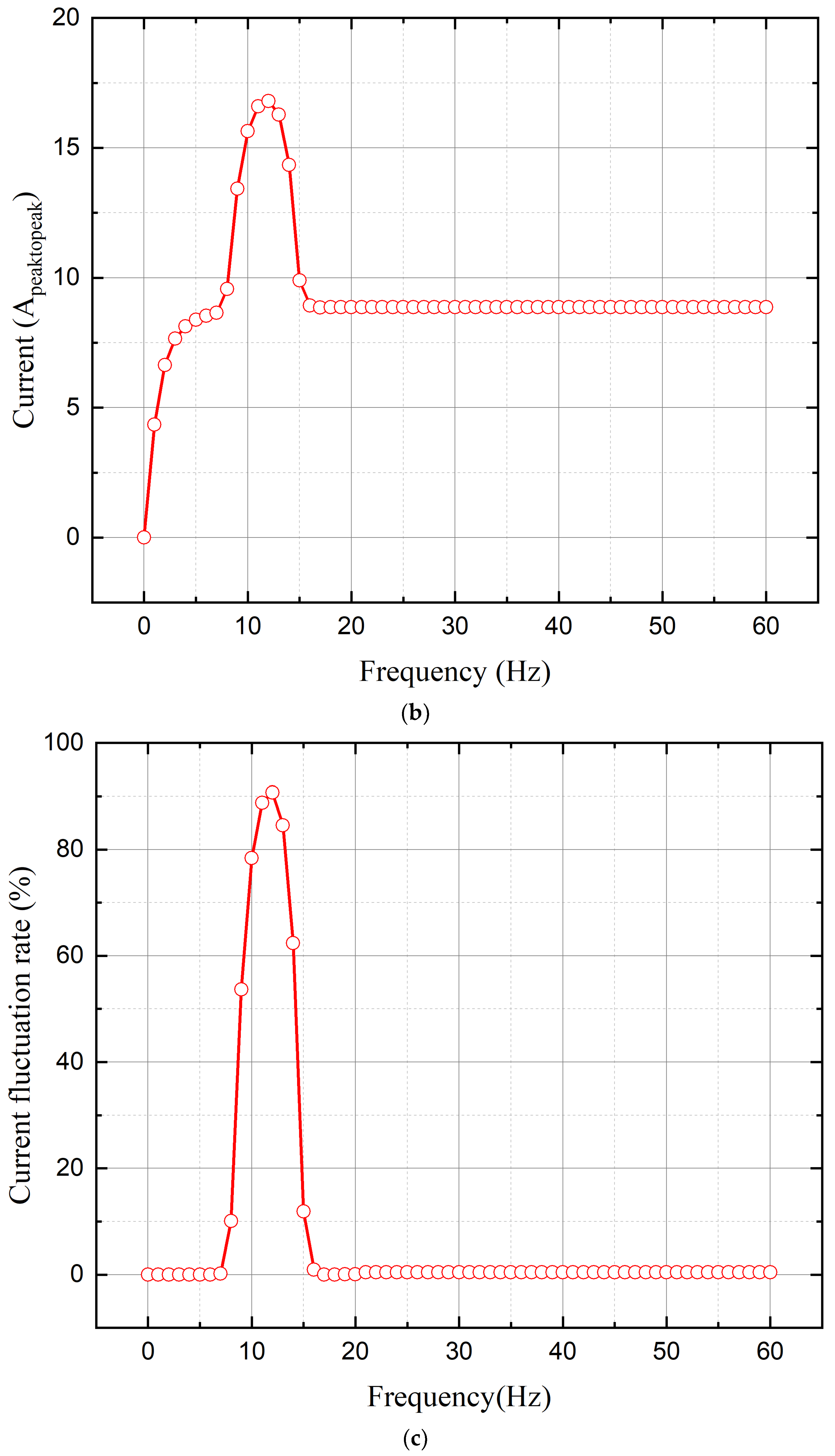
3.1. Characteristic Analysis Based on the Rotor Moment of Inertia
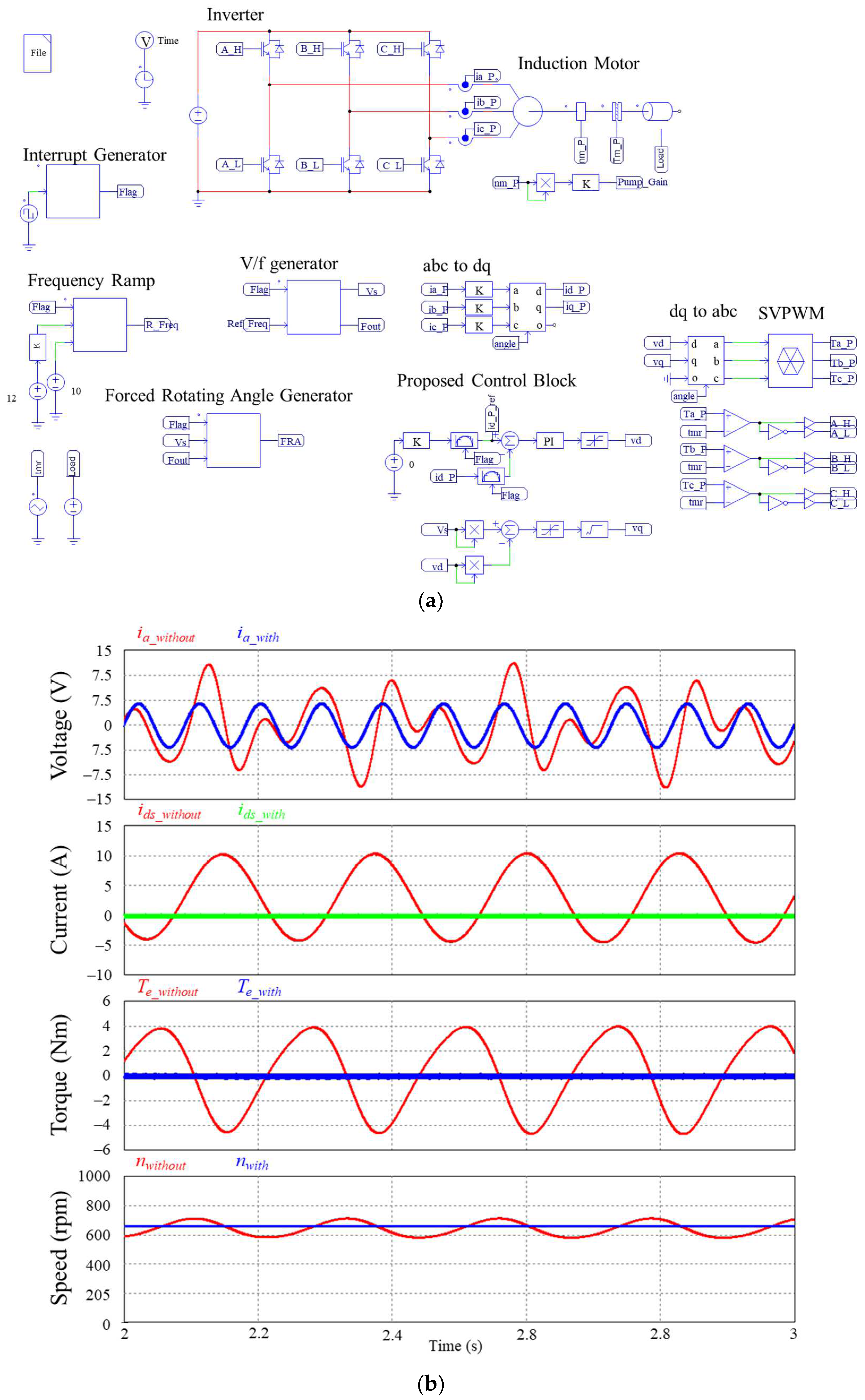
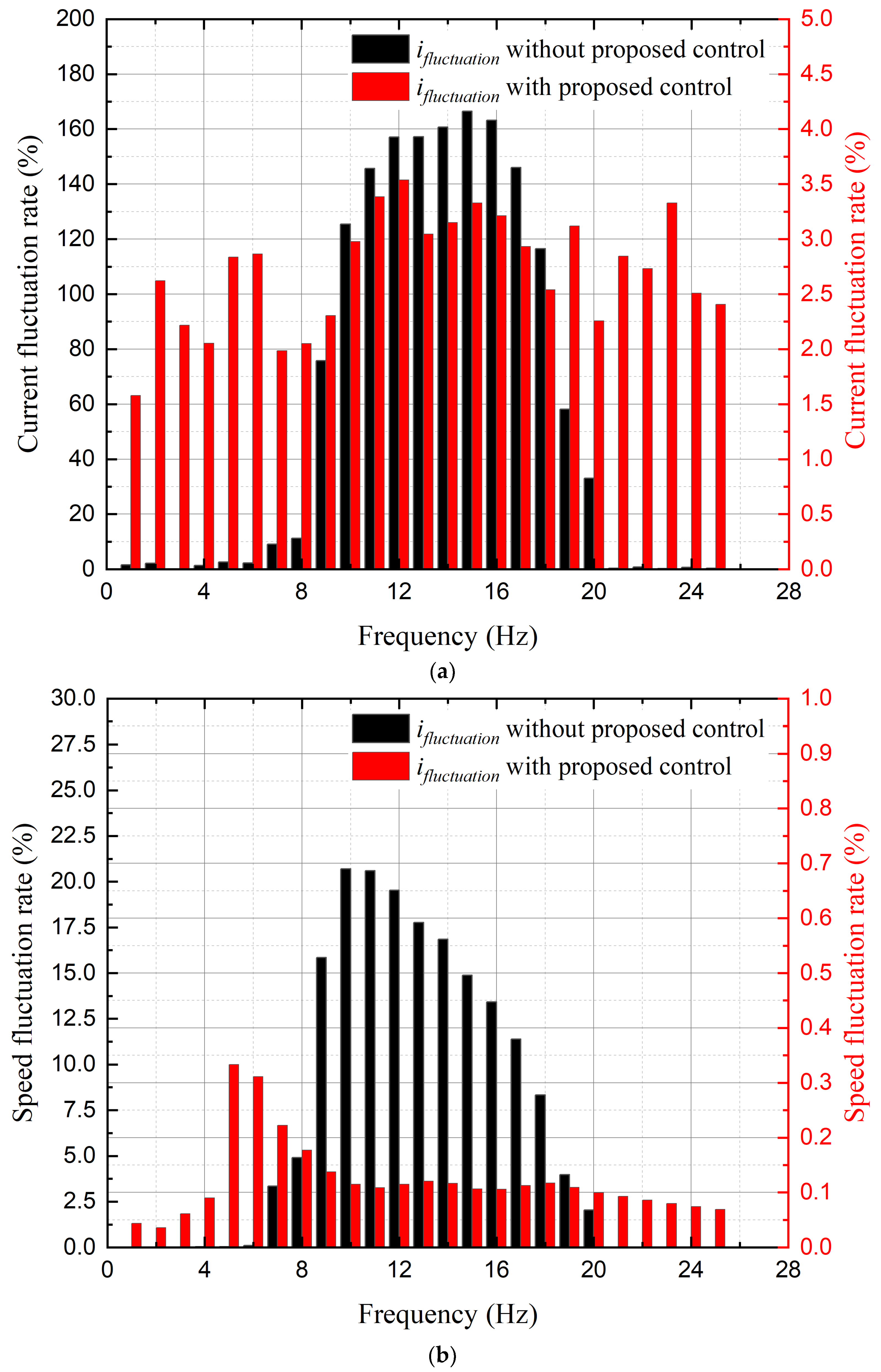
3.2. Simulation Results Using PWM Inverter
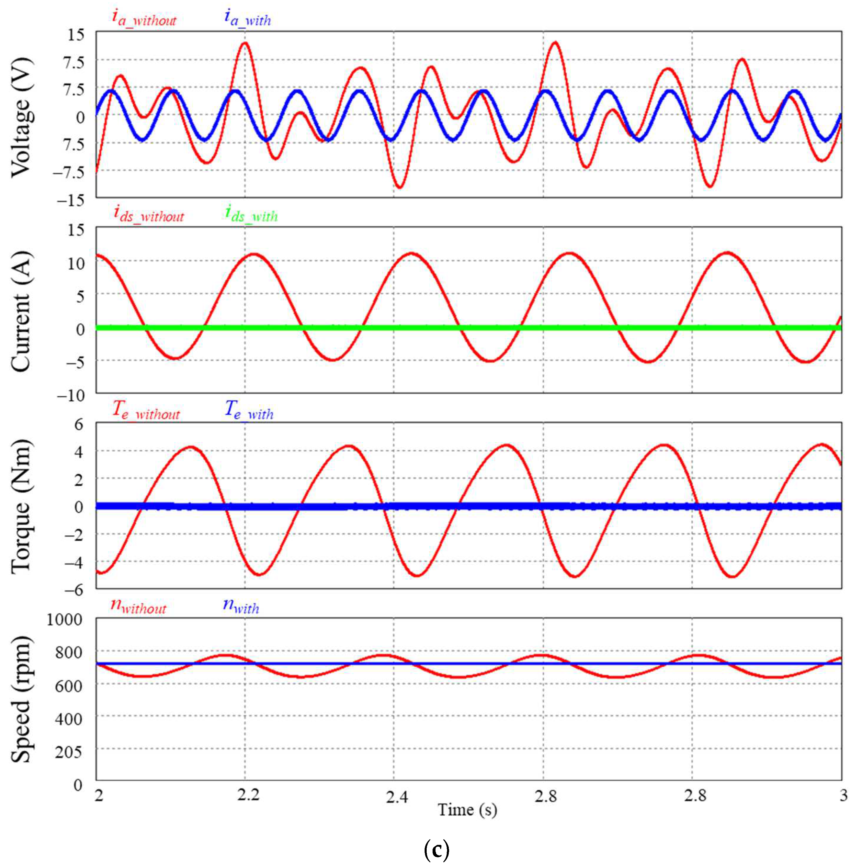
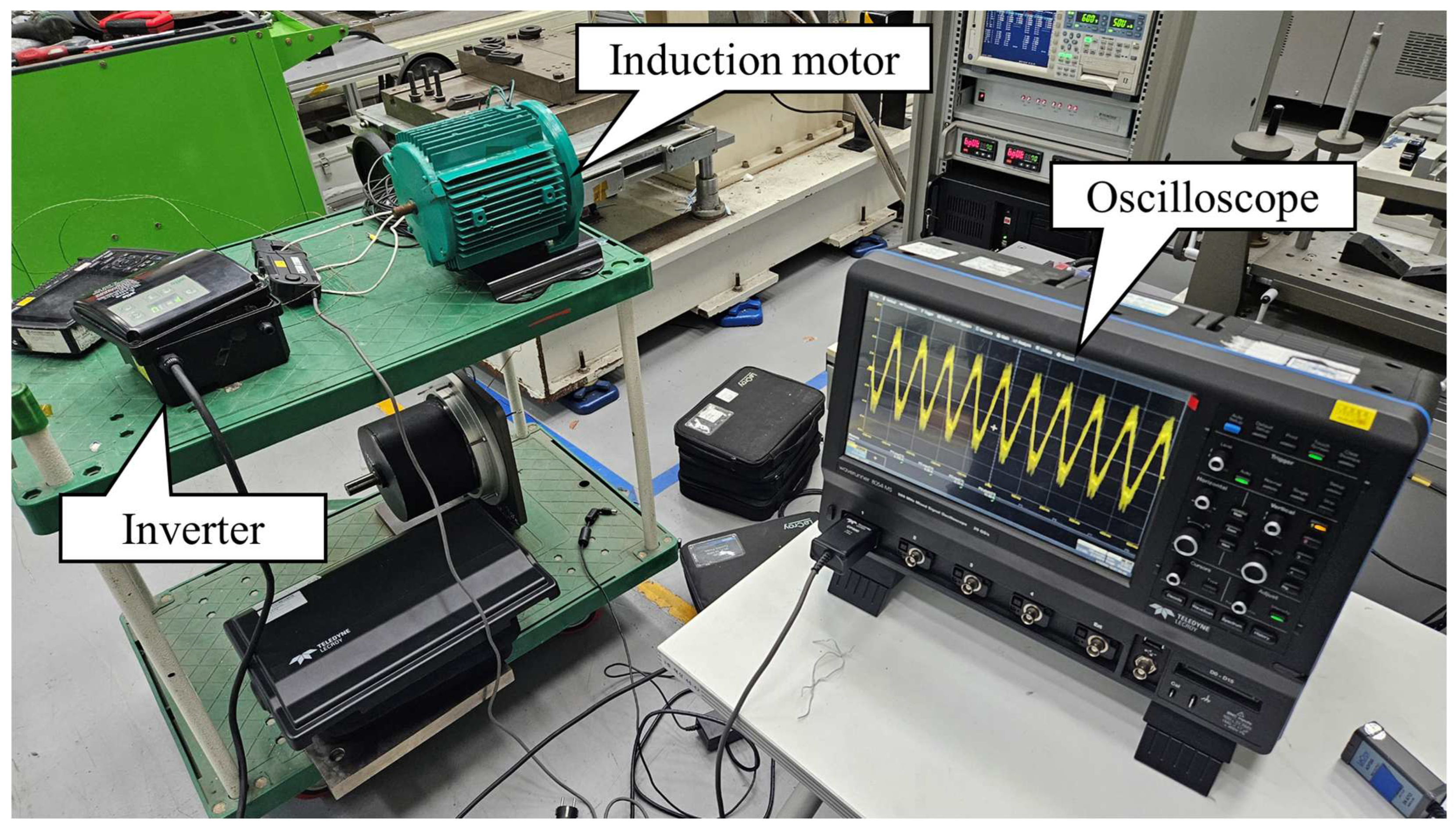
3.3. Experimental Results
4. Conclusions
Author Contributions
Funding
Data Availability Statement
Conflicts of Interest
References
- Teixeira, A.C.R.; Sodré, J.R. Impacts of Replacement of Engine Powered Vehicles by Electric Vehicles on Energy Consumption and CO2 Emissions. Transp. Res. Part D Transp. Environ. 2018, 59, 375–384. [Google Scholar] [CrossRef]
- Gobbi, M.; Sattar, A.; Palazzetti, R.; Mastinu, G. Traction Motors for Electric Vehicles: Maximization of Mechanical Efficiency—A Review. Appl. Energy 2024, 357, 122496. [Google Scholar] [CrossRef]
- Konda, Y.R.; Ponnaganti, V.K.; Reddy, P.V.S.; Singh, R.R.; Mercorelli, P.; Gundabattini, E.; Solomon, D.G. Thermal Analysis and Cooling Strategies of High-Efficiency Three-Phase Squirrel-Cage Induction Motors—A Review. Computation 2024, 12, 6. [Google Scholar] [CrossRef]
- Lee, K.; Han, Y. Reactive-Power-Based Robust MTPA Control for V/f Scalar-Controlled Induction Motor Drives. IEEE Trans. Ind. Electron. 2022, 69, 169–178. [Google Scholar] [CrossRef]
- Lipo, T.A.; Krause, P.C. Stability analysis of a rectifier-inverter induction motor drive. IEEE Trans. Power Appar. Syst. 1969, PAS-88, 55–66. [Google Scholar] [CrossRef]
- Ueda, R.; Sonoda, T.; Takata, S. Experimental Results and Their Simplified Analysis on Instability Problems in PWM Inverter Induction Motor Drives. IEEE Trans. Ind. Appl. 1989, 25, 86–95. [Google Scholar] [CrossRef]
- Oteafy, A.; Chiasson, J. A study of the Lyapunov stability of an open-loop induction machine. IEEE Trans. Control Syst. Technol. 2010, 18, 1469–1476. [Google Scholar] [CrossRef]
- Jung, J.-H.; Jeong, G.-Y.; Kwon, B.-H. Stability Improvement of V/f Controlled Induction Motor Drive Systems by a Dynamic Current Compensator. IEEE Trans. Ind. Electron. 2004, 51, 930–933. [Google Scholar] [CrossRef]
- Samal, K.B.; Pati, S.; Sharma, R. Integration of a Proton Exchange Membrane Fuel Cell System for Voltage and Frequency Stabilization in a Micro Hydro System. E-Prime-Adv. Electr. Eng. Electron. Energy 2024, 7, 100428. [Google Scholar] [CrossRef]
- Zagirnyak, M.; Korenkova, T.; Kovalchuk, V.; Szczęsny, A.; Korzeniewska, E. The Analysis of Operation Modes of Variable Speed Pump Units with Different Circuits of Turbomachine Connection. Energies 2024, 17, 882. [Google Scholar] [CrossRef]
- Shakweh, Y. Variable Speed Drive Types and Specifications. In Power Electronics Handbook; Butterworth-Heinemann: Oxford, UK, 2024; pp. 1037–1072. [Google Scholar]
- Chuensiri, S.; Katchasuwanmanee, K.; Wisessint, A.; Jotisankasa, A.; Soralump, C.; Siriyakorn, V.; Sanposh, P. Implementation of Adaptive Network-Based Fuzzy Inference for Hybrid Ground Source Heat Pump. IEEE Access 2024, 12, 21052–21069. [Google Scholar] [CrossRef]
- Gao, M.; Wang, Q.; Shan, X.; Li, Q.; Zhang, L. Application of Hydraulic Energy-Saving Technology in the Teaching, Research, and Practice of Mechanical Engineering. Sustainability 2024, 16, 1315. [Google Scholar] [CrossRef]
- Wang, S.; Prystupa, D.; Bao, Y.; Varvolik, V.; Buticchi, G.; Zhang, H.; Degano, M. Comprehensive Modulation Strategies for Synchronous Reluctance Motor Drives Used in Weak Grids. Energies 2024, 17, 615. [Google Scholar] [CrossRef]
- Elgbaily, M.; Anayi, F.; Alshbib, M.M. A Combined Control Scheme of Direct Torque Control and Field-Oriented Control Algorithms for Three-Phase Induction Motor: Experimental Validation. Mathematics 2022, 10, 3842. [Google Scholar] [CrossRef]
- El Ouanjli, N.; Derouich, A.; El Ghzizal, A. Modern Improvement Techniques of Direct Torque Control for Induction Motor Drives—A Review. Prot. Control Mod. Power Syst. 2019, 4, 11. [Google Scholar] [CrossRef]
- Narayana, K.S.; Surekha, P.; Prasuna, P.V. A New FOC Approach of Induction Motor Drive Using DTC Strategy for the Minimization of CMV. Int. J. Power Electron. Drive Syst. 2013, 3, 241. [Google Scholar] [CrossRef]
- Jnayah, S.; Khedher, A. DTC of Induction Motor Drives Fed by Two and Three-Level Inverter: Modeling and Simulation. In Proceedings of the 2019 19th International Conference on Sciences and Techniques of Automatic Control and Computer Engineering (STA), Sousse, Tunisia, 24–26 March 2019. [Google Scholar]
- Casadei, D.; Profumo, F.; Serra, G.; Tani, A. FOC and DTC: Two Viable Schemes for Induction Motors Torque Control. IEEE Trans. Power Electron. 2002, 17, 779–787. [Google Scholar] [CrossRef]
- Graciola, C.L.; Goedtel, A.; Angélico, B.A. Energy Efficiency Optimization Strategy for Scalar Control of Three-Phase Induction Motors. J. Control Autom. Electr. Syst. 2022, 33, 1032–1043. [Google Scholar] [CrossRef]
- Hoang, M.H.; Ahn, H.J. RTC (Reaction Torque Compensated) Induction Motor and Its Open-Loop Control. JMST Adv. 2019, 1, 23–30. [Google Scholar] [CrossRef]
- Duranay, Z.B.; Guldemir, H.; Tuncer, S. Implementation of a V/F Controlled Variable Speed Induction Motor Drive. EMITTER Int. J. Eng. Technol. 2020, 8, 35–48. [Google Scholar] [CrossRef]
- Selvan, S.; Venkadesan, A.; Sedhuraman, K. V/F Speed Control of Three-Phase and Five-Phase Induction Motor Drive: A Comparative Study. In Advances in Electrical and Computer Technologies; Sengodan, T., Murugappan, M., Misra, S., Eds.; ICAECT 2020, Lecture Notes in Electrical Engineering; Springer: Singapore, 2021; Volume 711. [Google Scholar]
- Munoz-Garcia, A.; Lipo, T.A.; Novotny, D.W. A New Induction Motor V/f Control Method Capable of High-Performance Regulation at Low Speeds. IEEE Trans. Ind. Appl. 1998, 34, 813–821. [Google Scholar] [CrossRef]
- Shetty, A.; Suryanarayana, K. Variable Frequency and Voltage Control of Induction Motor for Electric Vehicles. In Advances in Renewable Energy and Electric Vehicles; Sanjeevikumar, P., Prabhu, N., Suryanarayana, K., Eds.; Lecture Notes in Electrical Engineering; Springer: Singapore, 2022; Volume 767. [Google Scholar]
- Carbone, L.; Cosso, S.; Kumar, K.; Marchesoni, M.; Passalacqua, M.; Vaccaro, L. Stability Analysis of Open-Loop V/Hz Controlled Asynchronous Machines and Two Novel Mitigation Strategies for Oscillations Suppression. Energies 2022, 15, 1404. [Google Scholar] [CrossRef]
- Guha, A.; Narayanan, G. Small-Signal Stability Analysis of an Open-Loop Induction Motor Drive Including the Effect of Inverter Deadtime. IEEE Trans. Ind. Appl. 2016, 52, 242–253. [Google Scholar] [CrossRef]
- Hinkkanen, M.; Tiitinen, L.; Mölsä, E.; Harnefors, L. On the Stability of Volts-Per-Hertz Control for Induction Motors. IEEE J. Emerg. Sel. Top. Power Electron. 2022, 10, 1609–1618. [Google Scholar] [CrossRef]
- Xiang, Y.Q. Instability Compensation of V/Hz PWM Inverter-Fed Induction Motor Drives. In Proceedings of the IEEE Conference Record Industrial Applications Conference 32nd IAS Annual Meeting, New Orleans, LA, USA, 5–9 October 1997; pp. 613–620. [Google Scholar]
- Ma, Z.; Lin, F.; Zheng, T.Q. A New Stabilizing Control Method for Suppressing Oscillations of V/Hz Controlled PWM Inverter-Fed Induction Motors Drives. In Proceedings of the IEEE 37th Power Electronics Specialists Conference, Jeju, Republic of Korea, 18–22 June 2006; pp. 1–4. [Google Scholar]
- Suzuki, K.; Saito, S.; Kudor, T.; Tanaka, A.; Andoh, Y. Stability improvement of V/F controlled large capacity voltage-source inverter fed induction motor. In Proceedings of the Conference Record of the 2006 IEEE Industry Applications Conference Forty-First IAS Annual Meeting, Tampa, FL, USA, 8–12 October 2006; pp. 90–95. [Google Scholar]
- Qian, Z.; Yao, W.; Lee, K. Stability analysis and improvement of V/Hz controlled adjustable speed drives equipped with small DC-link thin film capacitors. In Proceedings of the 2018 IEEE Applied Power Electronics Conference and Exposition (APEC), San Antonio, TX, USA, 4–8 March 2018; pp. 861–866. [Google Scholar]
- Zhang, S.; Kang, J.; Yuan, J. Analysis and suppression of oscillation in V/F controlled induction motor drive systems. IEEE Trans. Transp. Electrif. 2022, 8, 1566–1574. [Google Scholar] [CrossRef]


| Item | Unit | Model A | Model B |
|---|---|---|---|
| Rated power | W | 746 | 746 |
| Input voltage | V | 220 | 220 |
| Base frequency | Hz | 60 | 60 |
| Rated speed | rpm | 3565 | 3565 |
| Rated current | A | 3.7 | 3.7 |
| Stator resistance | Ω | 1.2 | 1.2 |
| Stator inductance | mH | 107 | 107 |
| Rotor resistance | Ω | 0.57 | 0.57 |
| Rotor inductance | mH | 107 | 107 |
| Mutual inductance | mH | 105.5 | 105.5 |
| Poles | - | 2 | 2 |
| Moment of inertia of the rotor | kg/m2 | 0.0022 | 0.022 |
| Frequency (Hz) | Normal Current (Apeaktopeak) | Without Proposed Control | With Proposed Control | ||
|---|---|---|---|---|---|
| Fluctuation Current (Apeaktopeak) | Current Fluctuation Rate (%) | Fluctuation Current (Apeaktopeak) | Current Fluctuation Rate (%) | ||
| 10 | 8.573 | 17.01 | 98.41 | 9.24 | 7.78 |
| 11 | 8.573 | 17.85 | 108.21 | 9.24 | 7.78 |
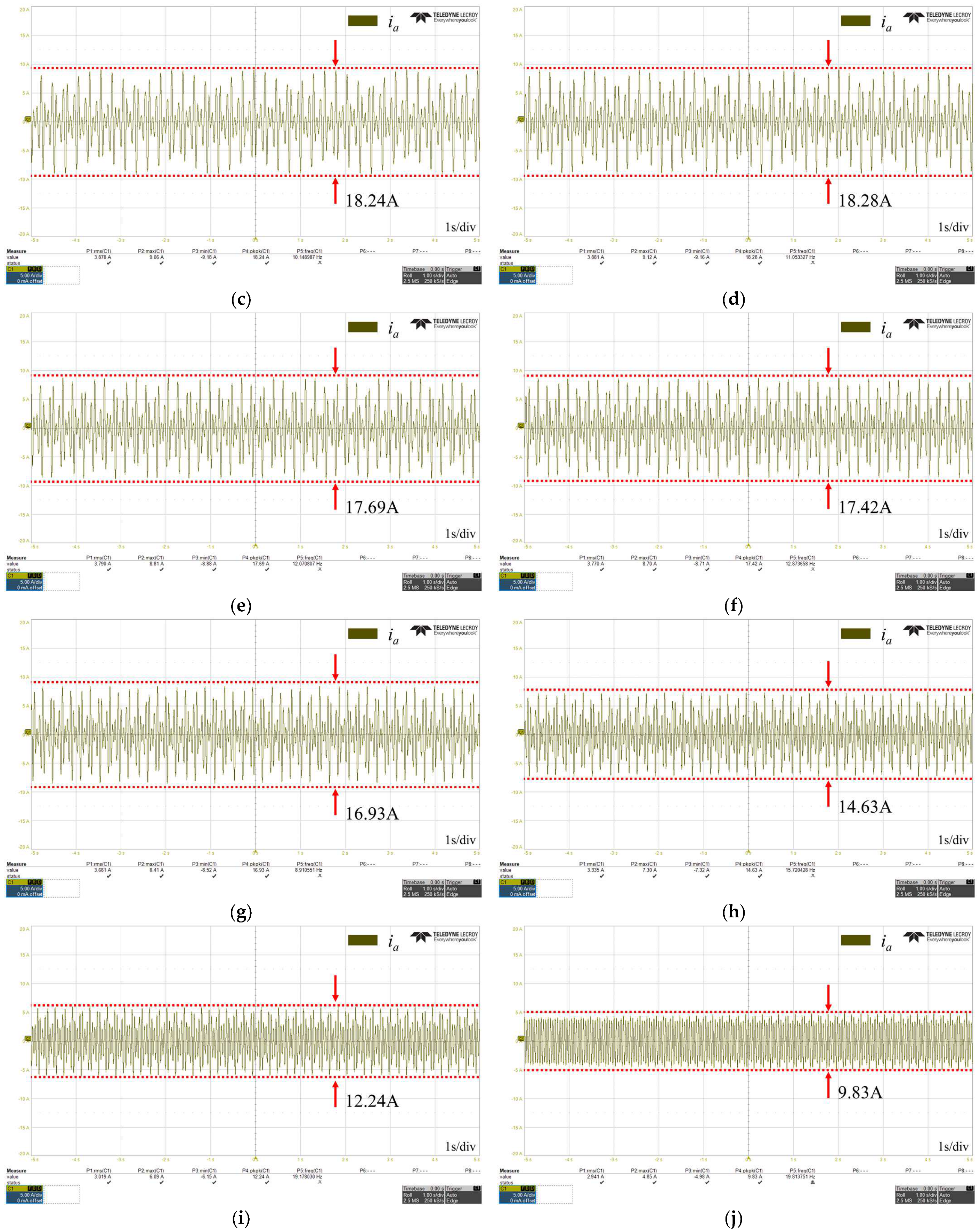
| 12 | 8.573 | 18.24 | 112.76 | 9.24 | 7.78 |
| 13 | 8.5701 | 18.28 | 113.3 | 9.252 | 7.96 |
| 14 | 8.5701 | 17.69 | 106.41 | 9.245 | 7.88 |
| 15 | 8.573 | 17.42 | 103.2 | 9.307 | 8.56 |
| 16 | 8.573 | 16.93 | 97.48 | 9.273 | 8.17 |
| 17 | 8.573 | 14.63 | 70.65 | 9.256 | 7.97 |
| 18 | 8.573 | 12.24 | 42.77 | 9.257 | 7.98 |
| 19 | 8.5701 | 9.83 | 14.70 | 9.249 | 7.92 |
Disclaimer/Publisher’s Note: The statements, opinions and data contained in all publications are solely those of the individual author(s) and contributor(s) and not of MDPI and/or the editor(s). MDPI and/or the editor(s) disclaim responsibility for any injury to people or property resulting from any ideas, methods, instructions or products referred to in the content. |
© 2024 by the authors. Licensee MDPI, Basel, Switzerland. This article is an open access article distributed under the terms and conditions of the Creative Commons Attribution (CC BY) license (https://creativecommons.org/licenses/by/4.0/).
Share and Cite
Son, D.-H.; Kim, S.-A. Simplified V/f Control Algorithm for Reduction of Current Fluctuations in Variable-Speed Operation of Induction Motors. Energies 2024, 17, 1699. https://doi.org/10.3390/en17071699
Son D-H, Kim S-A. Simplified V/f Control Algorithm for Reduction of Current Fluctuations in Variable-Speed Operation of Induction Motors. Energies. 2024; 17(7):1699. https://doi.org/10.3390/en17071699
Chicago/Turabian StyleSon, Dong-Hyeok, and Sung-An Kim. 2024. "Simplified V/f Control Algorithm for Reduction of Current Fluctuations in Variable-Speed Operation of Induction Motors" Energies 17, no. 7: 1699. https://doi.org/10.3390/en17071699