
Research on the Temperature Distribution in Electrically Heated Offshore Heavy Oil Wellbores

Abstract
:1. Introduction
2. Mathematical Model
2.1. Model Assumptions
- The flow of heavy oil in a tubing is one-dimensional.
- Only the radial heat transfer from the wellbore is considered, and the axial heat transfer from the wellbore is ignored.
- Heavy oil is incompressible, and its viscosity changes during production.
- Consider the thermal effects generated during the flow process of heavy oil.
2.2. Distribution Model of Wellbore Temperature Field
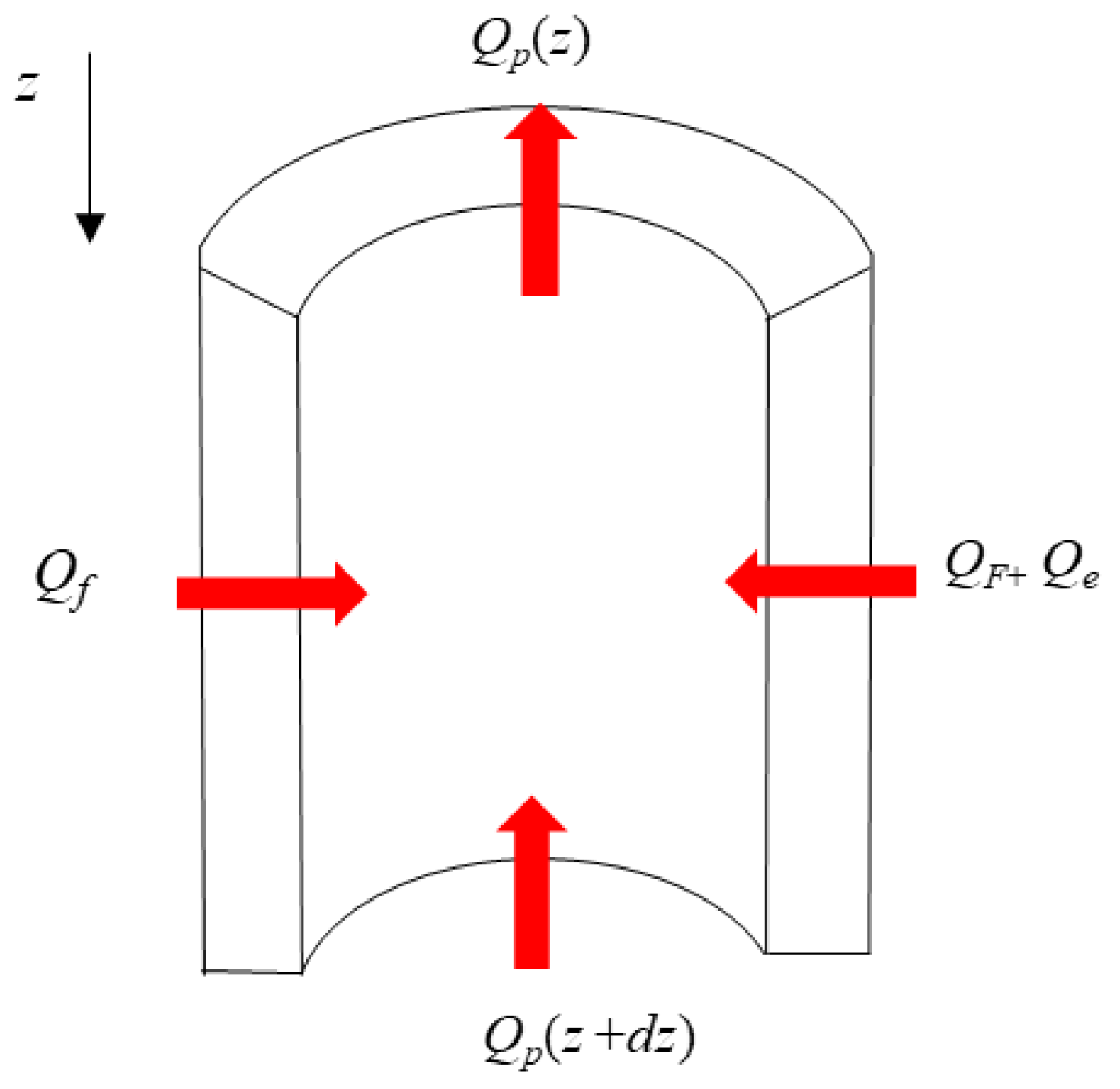
2.2.1. Governing Equation
2.2.2. Auxiliary Equation
- (1)
- Calculation of convective heat transfer coefficient hf.
- (2)
- Calculation of the heat transfer coefficient hr for thermal radiation in the annulus.
- (3)
- Calculation of natural conductive heat transfer coefficient [24].
- (4)
- Calculation of convective heat transfer coefficients between seawater and riser [25].
- (5)
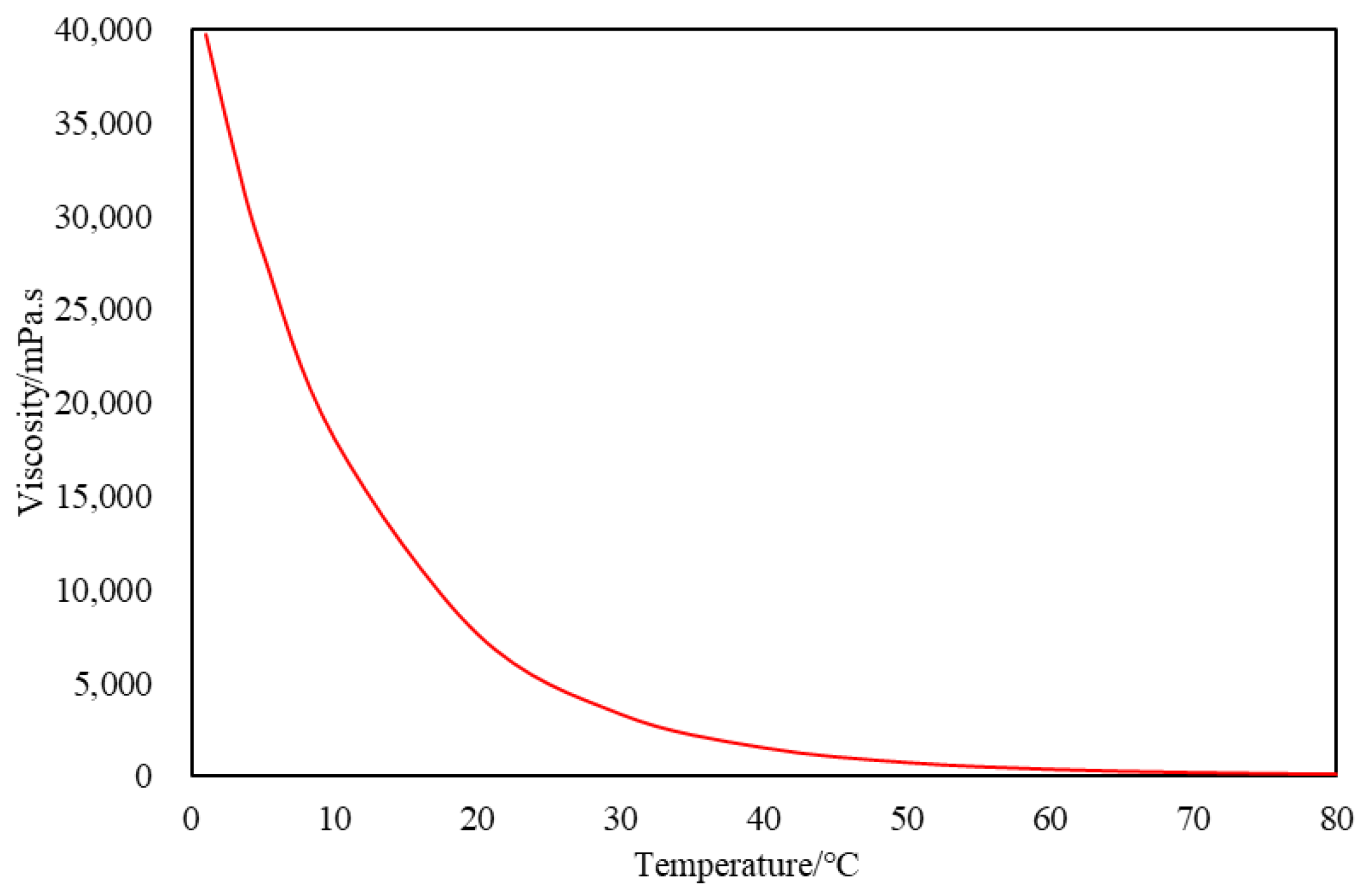
- The relationship between crude oil viscosity and temperature [26] is shown in Equation (15). The viscosity–temperature curve of crude oil is plotted based on the viscosity–temperature relationship, as shown in Figure 2. The inflection point temperature of the crude oil can be determined as 40 °C based on Figure 2. The viscosity μ of crude oil is mainly used for calculating the heat transfer coefficient hf.
2.3. Model Solving Conditions
2.3.1. Initial Conditions
2.3.2. Boundary Conditions
2.4. Numerical Solution
2.4.1. Discretization of Equations
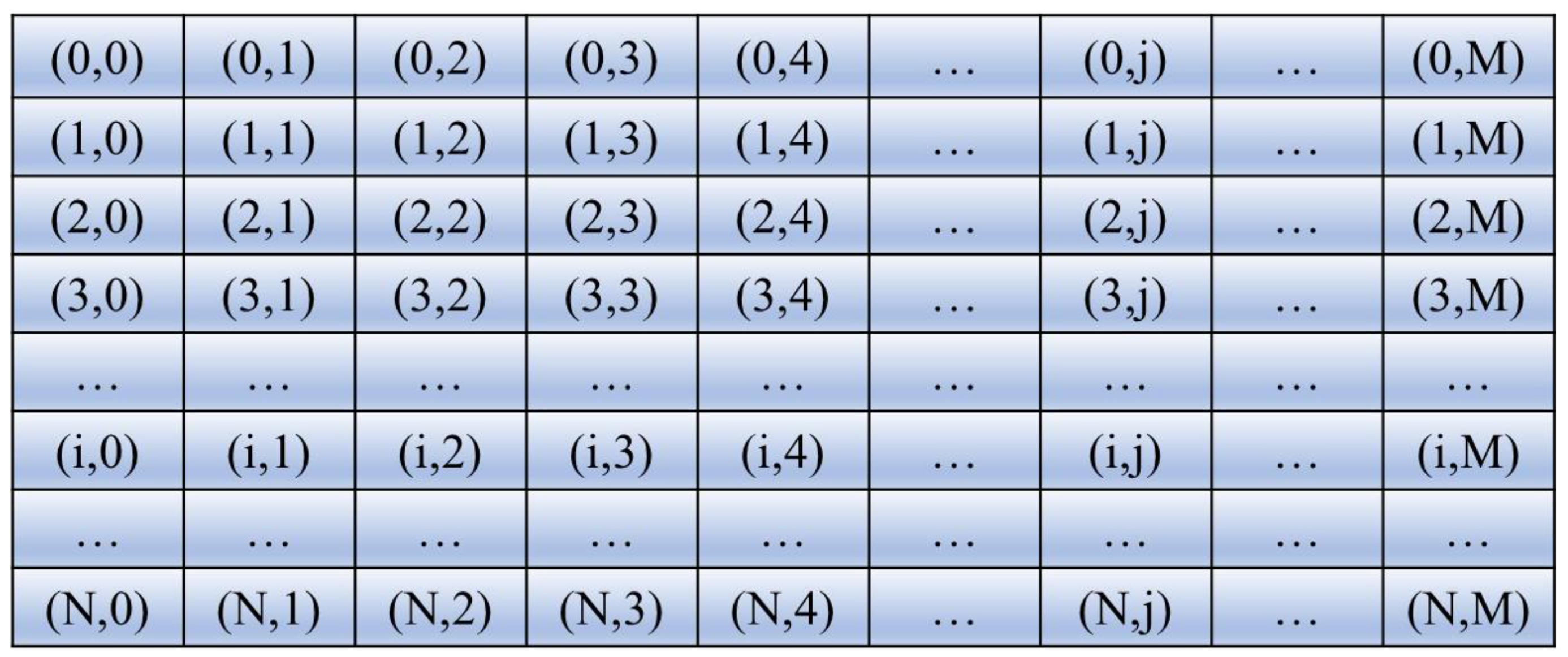
2.4.2. Meshing
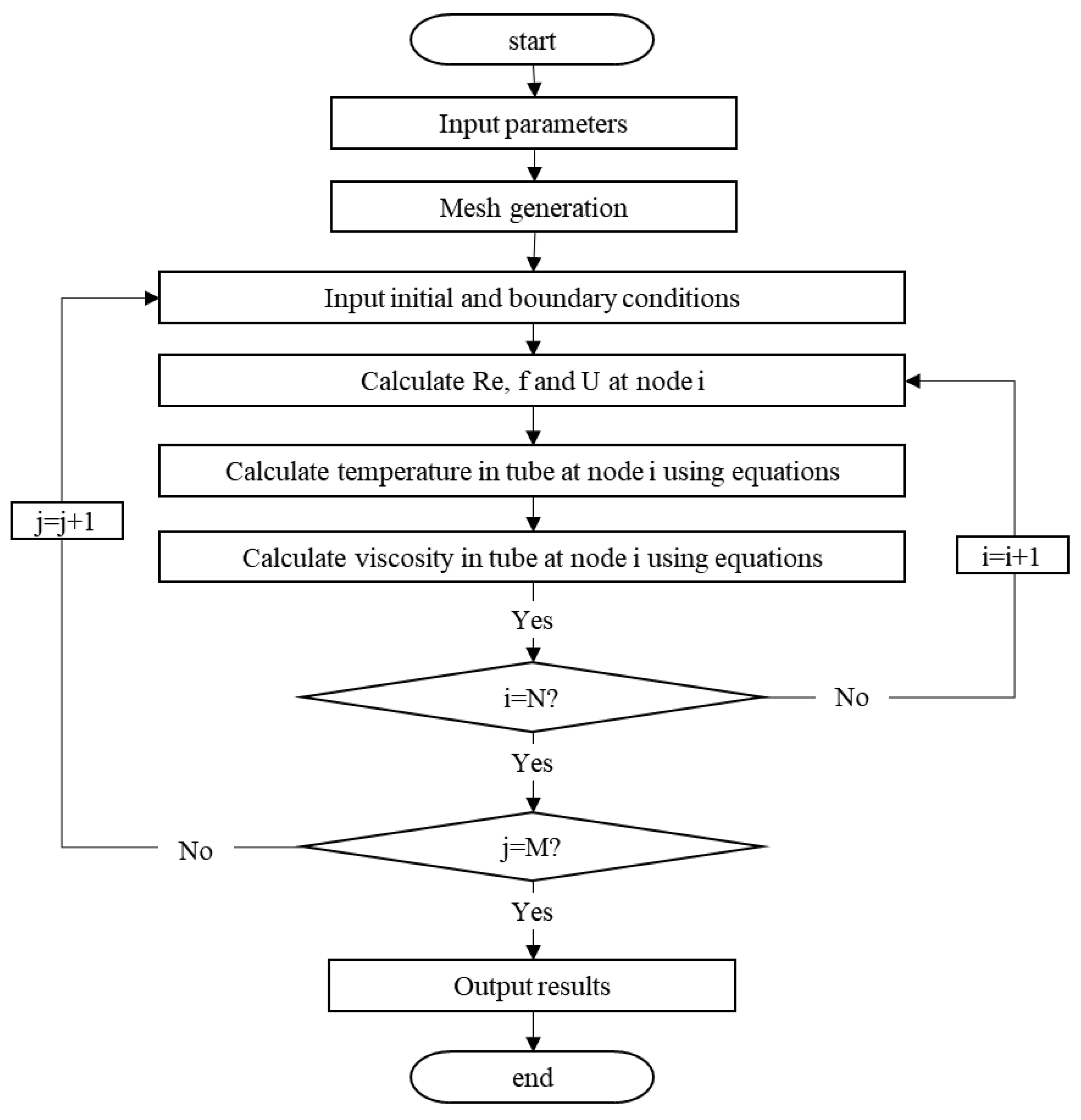
2.4.3. Solution
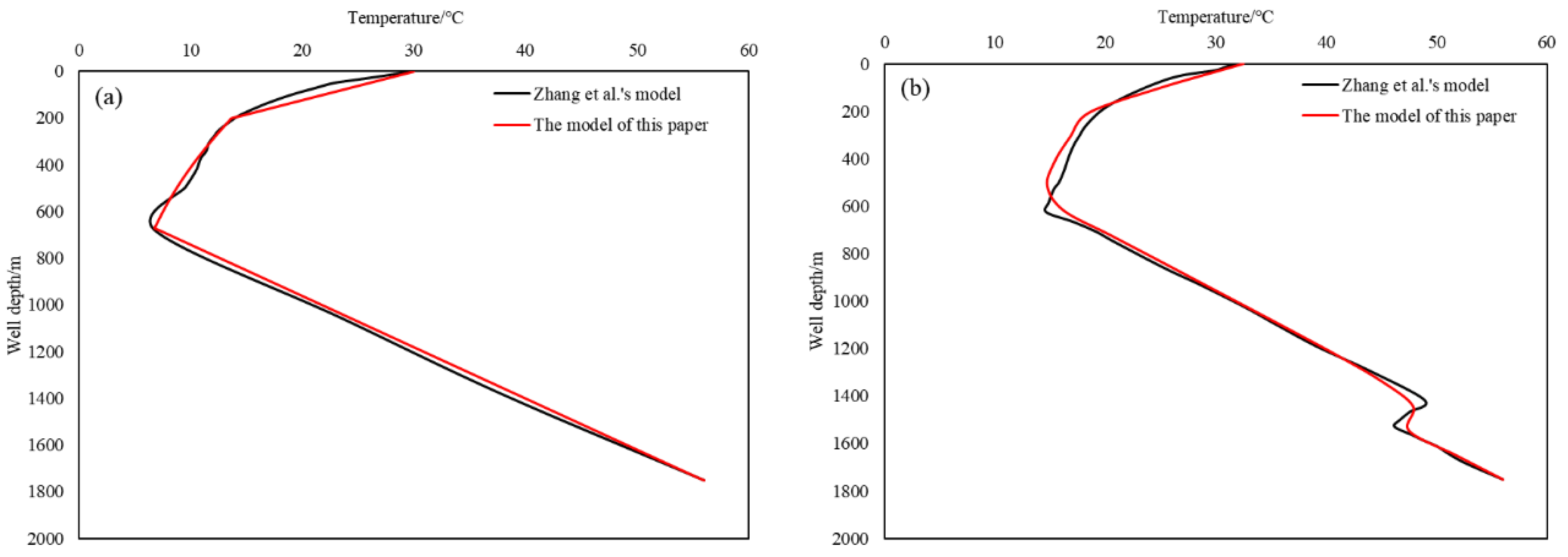
2.5. Model Validation
3. Sensitivity Analysis
3.1. Basic Data
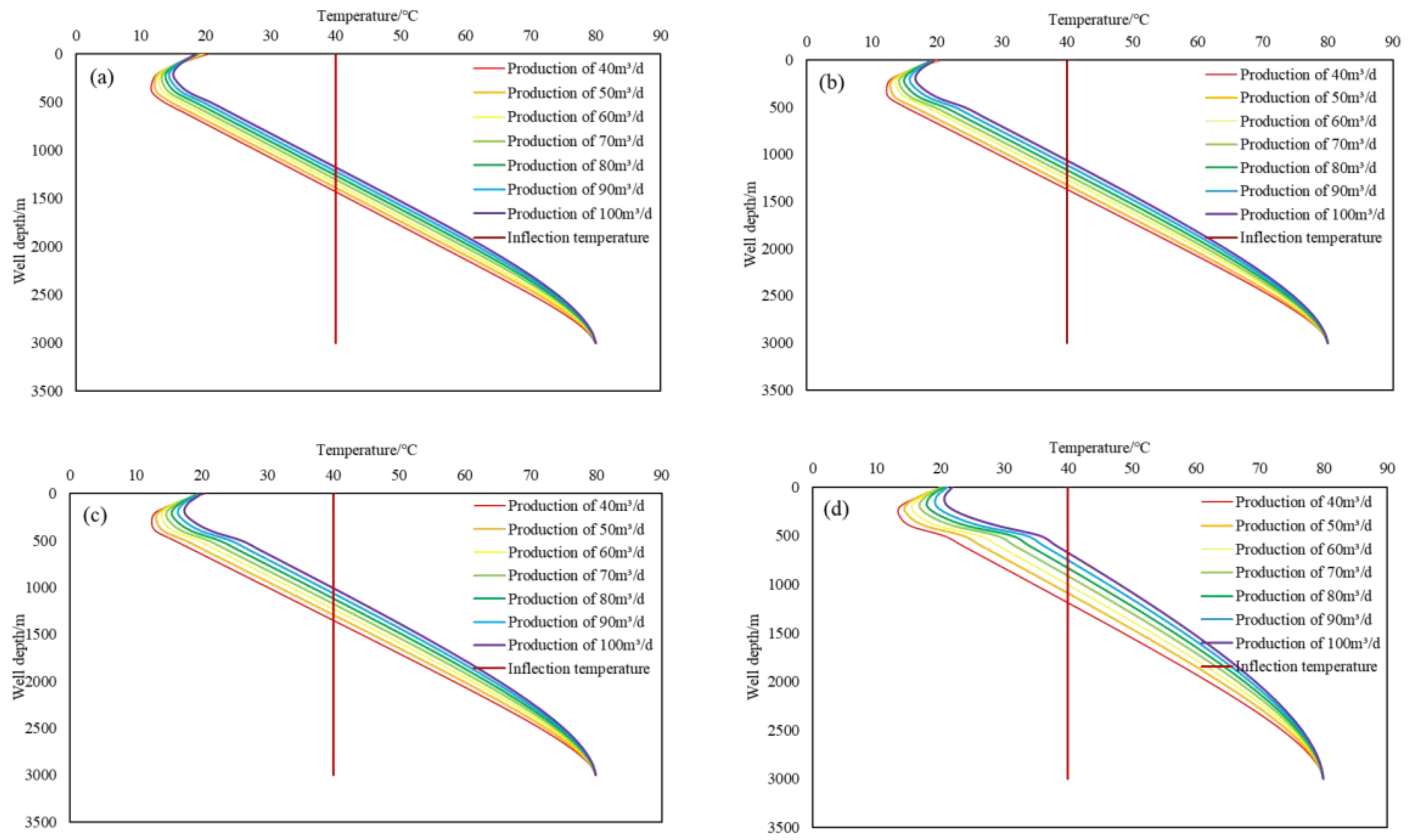
3.2. The Influence of Oil Production on the Temperature Distribution of Heavy Oil Wellbore
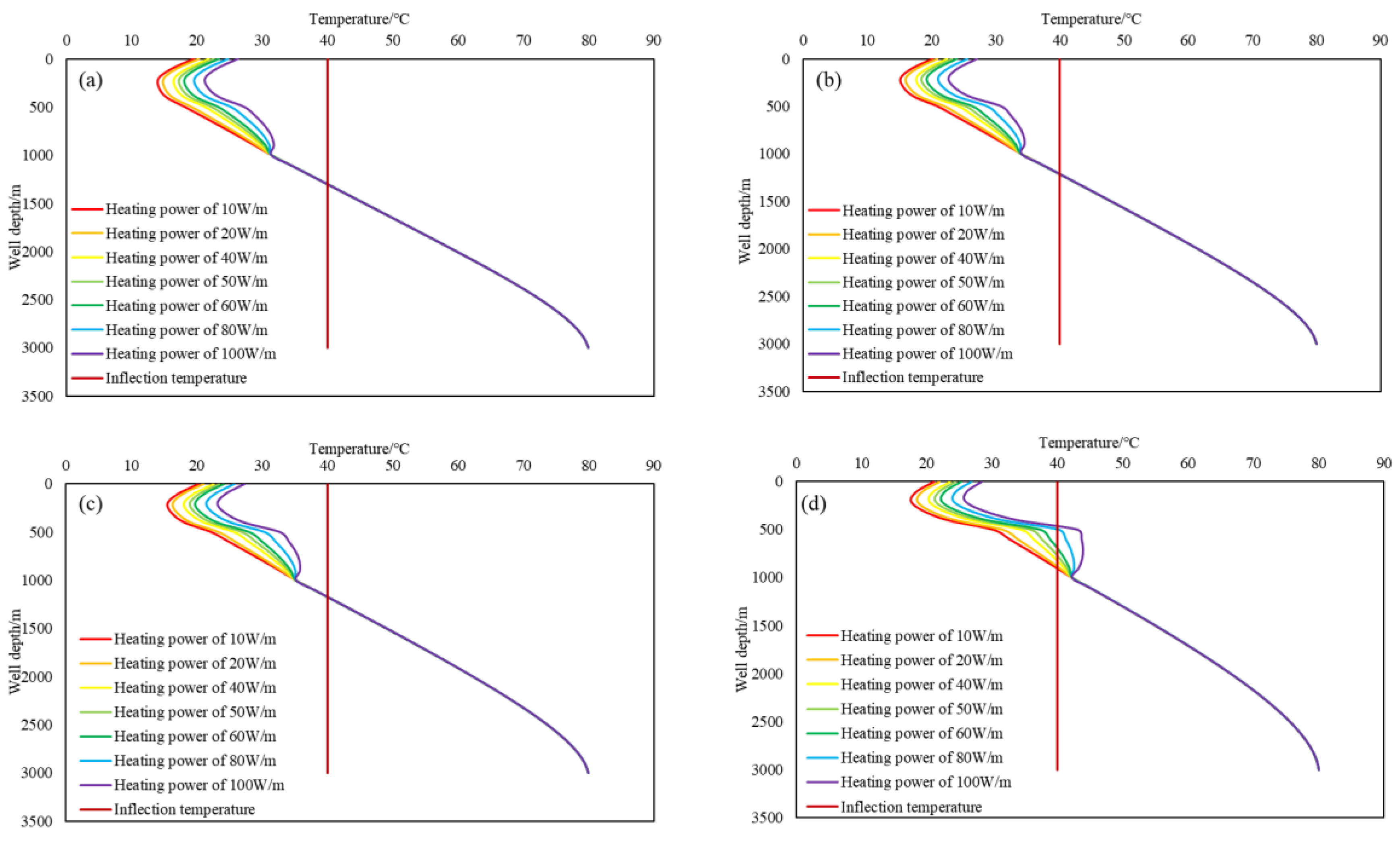
3.3. The Influence of Heating Power on the Temperature Distribution of Heavy Oil Wellbore
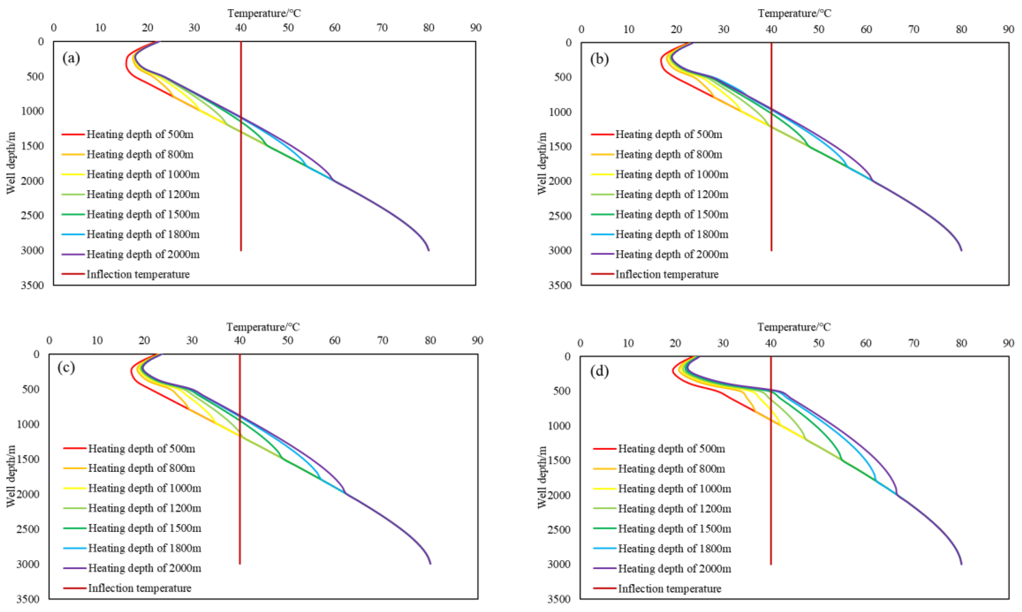
3.4. The Influence of Heating Depth on the Temperature Distribution of Heavy Oil Wellbore
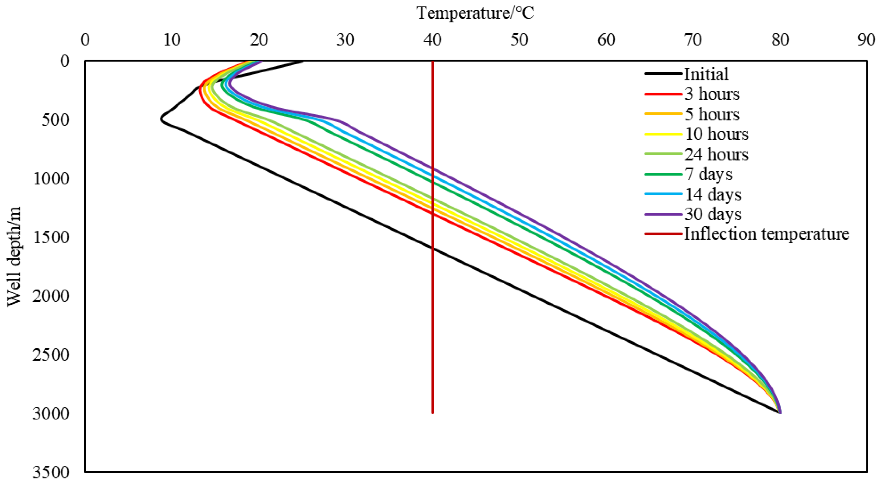
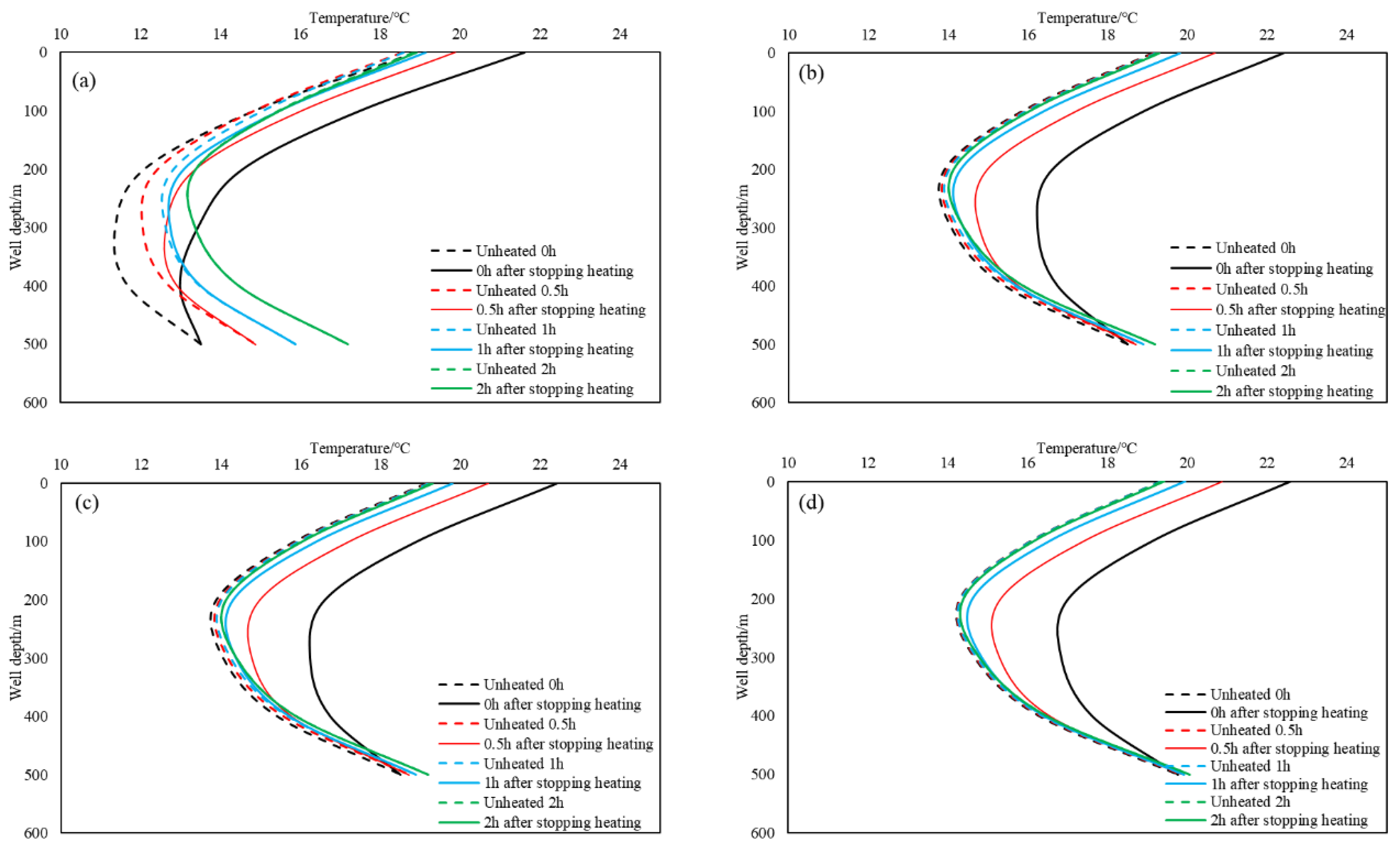
3.5. The Influence of Heating Time on the Temperature Distribution of Heavy Oil Wellbore
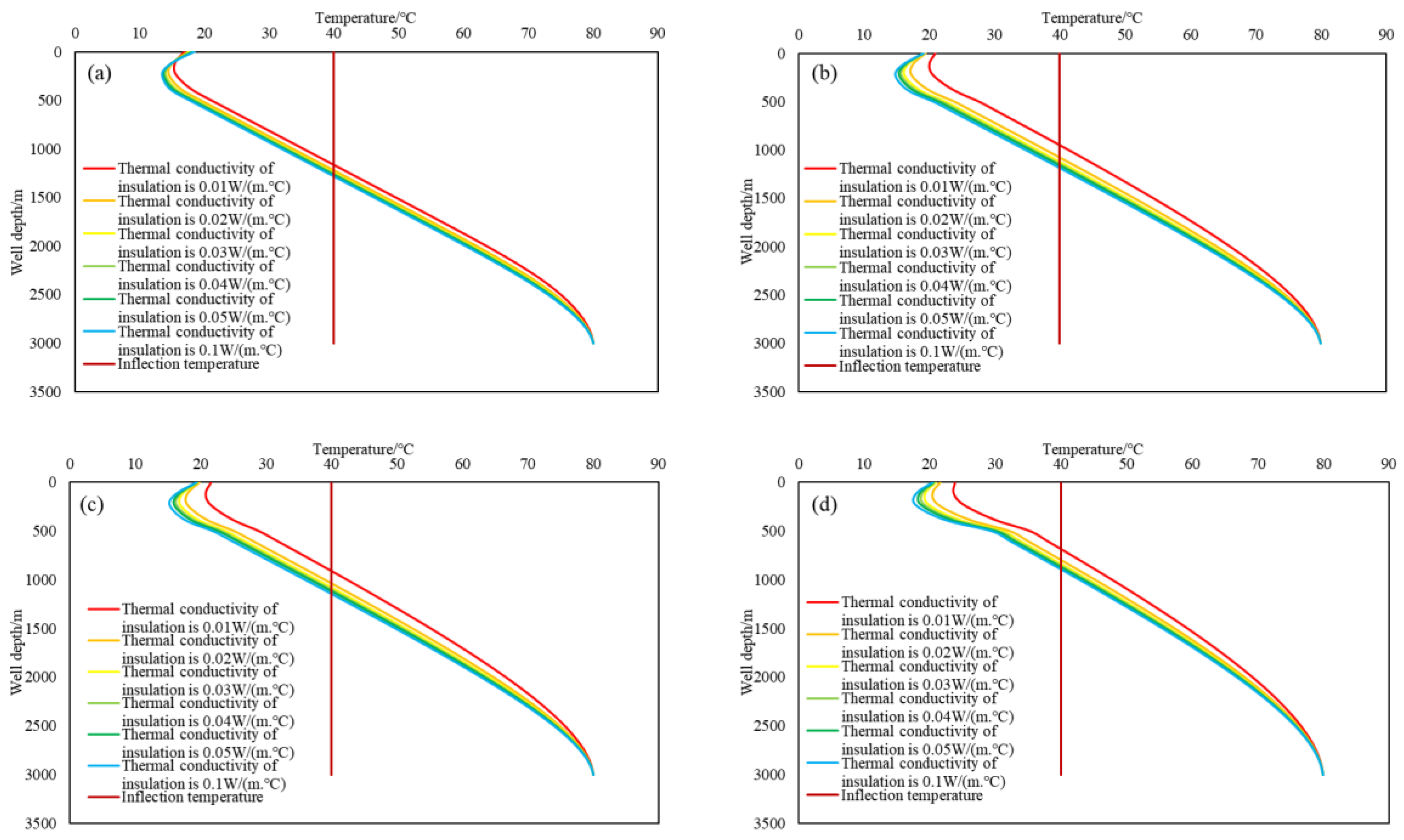
3.6. The Influence of Thermal Conductivity of Insulation Materials on the Temperature Distribution of Heavy Oil Wellbore
4. Conclusions
- (1)
- The higher the production, the higher the wellbore temperature distribution. With the increase in extraction time, the more obvious the distinction between the wellbore temperature distribution with different production. However, at the initial stage of heavy oil extraction, at a certain depth in the seawater section, the higher the production, the lower the temperature.
- (2)
- The higher the heating power and heating depth, the higher the wellbore temperature distribution. With the increase in extraction time, the distinction between the wellbore temperature distribution in the formation section under different heating power becomes more obvious, but the seawater section is not very obvious. The heating depth has some limitations, and the increase in heavy oil temperature is not obvious after the lowering depth reaches a certain value.
- (3)
- By adopting intermittent heating measures, more power resources can be saved while ensuring that the temperature of the heavy oil is higher than the inflection point temperature. When intermittent heating processes are adopted, the intermittent time needs to be optimised according to the actual situation.
- (4)
- The smaller the thermal conductivity of the insulation material, the higher the temperature distribution of the wellbore in general, but in the initial stage of the extraction of heavy oil, at a certain depth in the seawater section, there will be a situation in which the smaller the thermal conductivity of the insulation layer, the lower the temperature.
- (5)
- The electric heating process can “compensate” for the heat lost during the flow of heavy oil, and the use of insulation materials can better “store” the heat, and the combination of the two can maintain the wellbore temperature distribution at a high level.
- (6)
- The overall temperature of the wellbore will increase with the increase in the extraction time, so the use of electric heating process and insulation materials can be reduced according to the actual situation after extracting the heavy oil for a period of time.
- (7)
- Through the influence of electric heating power, heating depth, heating time and thermal conductivity of insulation materials on wellbore temperature, the optimal process parameters of offshore electric heating for lifting heavy oil can be selected according to the actual situation on site.
Author Contributions
Funding
Data Availability Statement
Conflicts of Interest
Nomenclature
| A | cross-sectional area of tubing, m2; |
| API | API (American Petroleum Institute) gravity, °API; |
| ce | specific heat capacity of the formation, J/(kg·°C); |
| cf | specific heat capacity of heavy oil, J/(kg·°C); |
| hc | natural convection heat transfer coefficient, W/(m2·°C); |
| hf | convective heat transfer coefficient of heavy oil, W/(m2·°C); |
| hr | annular radiation heat transfer coefficient, W/(m2·°C); |
| hsea | convective heat transfer coefficient of seawater crossing the riser, W/(m2·°C); |
| ke | thermal conductivity of the formation, W/(m·°C); |
| Nu | Nusselt number, dimensionless; |
| Qe | heat generated by electric heating, W; |
| QF | heat generated by the flow of heavy oil, W; |
| Qf | heat transfer between the formation (seawater) and the wellbore, W; |
| Qp(z) | heat flow into the microelement, W; |
| Qp(z + dz) | heat flowing out of the microelement, W; |
| Qt | the change in heat in microelements, W; |
| Qw | the heat exchange between the formation and the wellbore, W; |
| Qwf | the heat exchange between the wellbore and the tube, W; |
| qe | power of heating rod, W/m; |
| rcem | radius of cement, m; |
| rci | inner radius of casing, m; |
| rco | outer radius of casing, m; |
| rri | inner radius of riser, m; |
| rro | outer radius of riser, m; |
| rti | inner radius of tube, m; |
| rto | outer radius of tube, m; |
| rw | radius of the wellbore, m; |
| T | temperature, °C; |
| Tci | inner wall temperature of casing, °C; |
| Te | temperature of the formation, °C; |
| formation temperature at node i, °C; | |
| Tf | temperature of heavy oil, °C; |
| temperature of heavy oil at node i at time 0, °C; | |
| temperature of heavy oil at node 0 at time j, °C; | |
| temperature of heavy oil at node i at time j, °C; | |
| temperature of heavy oil at node i at time j + 1, °C; | |
| temperature of heavy oil at node i + 1 at time j, °C; | |
| reservoir temperature, °C; | |
| Tto | outer wall temperature of tube, °C; |
| Twb | temperature of the well wall, °C; |
| t | time, s; |
| Usea | total heat transfer coefficient from tube to seawater, W/(m2·°C); |
| Uti | total heat transfer coefficient from tube to formation, W/(m2·°C); |
| v | flow rate of heavy oil, m/s; |
| w | mass flow rate of heavy oil, kg/s; |
| Δt | time step, s; |
| Δz | well depth step, m; |
| ε | surface emissivity of the pipe wall, dimensionless; |
| μ | viscosity of heavy oil, mPa.s; |
| λ | thermal conductivity of heavy oil, W/(m·°C); |
| λc | thermal conductivity of air, W/(m·°C); |
| λcas | thermal conductivity of casing, W/(m·°C); |
| λcem | thermal conductivity of cement, W/(m·°C); |
| λm | friction coefficient of pipe wall, dimensionless; |
| λr | thermal conductivity coefficient of riser, W/(m·°C); |
| λsea | thermal conductivity coefficient of seawater, W/(m·°C); |
| λtub | thermal conductivity coefficient of tube, W/(m·°C); |
| ρ | density, kg/m3; |
| ρe | density of the formation, kg/m3; |
| σ | Stefan–Boltzmann constant, W/(m2·°C4). |
References
- Wang, Z.; Gao, D.; Diao, B.; Tan, L.; Zhang, W.; Liu, K. Comparative performance of electric heater vs. RF heating for heavy oil recovery. Appl. Therm. Eng. 2019, 160, 114105. [Google Scholar] [CrossRef]
- Weichao, L.; Tao, Q.; Hongxiang, G.; Jifei, Y.; Xianfu, S. Research and Application of Wellbore Temperature Field Models forThermal Recovery Well in Offshore Heavy Oilfield. J. Southwest Pet. Univ. 2012, 34, 105. [Google Scholar]
- Jin, F.; Jiang, T.; Yuan, C.; Varfolomeev, M.A.; Wan, F.; Zheng, Y.; Li, X. An improved viscosity prediction model of extra heavy oil for high temperature and high pressure. Fuel 2022, 319, 123852. [Google Scholar] [CrossRef]
- Mukhametshina, A.; Martynova, E. Electromagnetic heating of heavy oil and bitumen: A review of experimental studies and field applications. J. Pet. Eng. 2013, 2013, 476519. [Google Scholar] [CrossRef]
- Bera, A.; Babadagli, T. Status of electromagnetic heating for enhanced heavy oil/bitumen recovery and future prospects: A review—ScienceDirect. Appl. Energy 2015, 151, 206–226. [Google Scholar] [CrossRef]
- Hasibuan, M.Y.; Regina, S.; Wahyu, R.; Situmorang, D.; Azmi, F.; Syahputra, R.; Batubara, L.P.Y.; Prabowo, F.; Setiawan, A.; Afin, M.F. Electrical heating for heavy oil: Past, current, and future prospect. Preprints 2020. [Google Scholar] [CrossRef]
- Kovaleva, L.; Davletbaev, A.; Babadagli, T.; Stepanova, Z. Effects of electrical and radio-frequency electromagnetic heating on the mass-transfer process during miscible injection for heavy-oil recovery. Energy Fuels 2011, 25, 482–486. [Google Scholar] [CrossRef]
- Rangel-German, E.; Schembre, J.; Sandberg, C.; Kovscek, A. Electrical-heating-assisted recovery for heavy oil. J. Pet. Sci. Eng. 2004, 45, 213–231. [Google Scholar] [CrossRef]
- Hascakir, B.; Babadagli, T.; Akin, S. Experimental and Numerical Modeling of Heavy-Oil Recovery by Electrical Heating. In Proceedings of the International Thermal Operations and Heavy Oil Symposium, Calgary, AB, Canada, 20–23 October 2008; OnePetro: Richardson, TX, USA, 2008. [Google Scholar]
- Vielma, W.; Congo, E.; Misenta, M.; Ponticiello, I.; Secco, G. Downhole electrical heating system: Feasibility of heavy oil implementation in offshore Congo. In Proceedings of the Abu Dhabi International Petroleum Exhibition and Conference, Abu Dhabi, United Arab Emirates, 1–4 November 2010; OnePetro: Richardson, TX, USA, 2010. [Google Scholar]
- Escobar-Remolina, J.; Barrios, W.; Ecopetrol, S.; Silva, B. Production Increase with Electric Heating Production Line Technology in an Extra-Heavy Oil Field in Colombia: Successful Case of Flow Assurance. In Proceedings of the SPE Annual Technical Conference and Exhibition, San Antonio, TX, USA, 8–10 October 2012; OnePetro: Richardson, TX, USA, 2012. [Google Scholar]
- Hakiki, F.; Aditya, A.; Ulitha, D.; Shidqi, M.; Adi, W.; Wibowo, K.; Barus, M. Well and inflow performance relationship for heavy oil reservoir under heating treatment. In Proceedings of the SPE/IATMI Asia Pacific Oil & Gas Conference and Exhibition, Jakarta, Indonesia, 17–19 October 2017; OnePetro: Richardson, TX, USA, 2017. [Google Scholar]
- Karanikas, J.; Pastor, G.; Penny, S.; Ciencia, T.Y.F. Downhole electric heating of heavy-oil wells. CT 2020, 10, 61–72. [Google Scholar] [CrossRef]
- Penny, S.; Karanikas, J.M.; Barnett, J.; Harley, G.; Hartwell, C.; Waddell, T. Field case studies of downhole electric heating in two horizontal Alberta heavy oil wells. In Proceedings of the SPE Annual Technical Conference and Exhibition, Calgary, AB, Canada, 30 September–2 October 2019; OnePetro: Richardson, TX, USA, 2019. [Google Scholar]
- Pengju, Z.; Hongjun, X.; Peiyu, Z.; Songlin, R.; Zhichao, C.; Xiaolong, W.; Fugang, L. Application of Hollow Sucker Rod Electrical Heating Production Technology in Santanghu Oilfield. Drill. Prod. Technol. 2020, 43, 114. [Google Scholar]
- Zhu, M.; Zhong, H.; Li, Y.; Zeng, C.; Gao, Y. Research on viscosity-reduction technology by electric heating and blending light oil in ultra-deep heavy oil wells. J. Pet. Explor. Prod. Technol. 2015, 5, 233–239. [Google Scholar] [CrossRef]
- Wang, Z.; Gao, D.; Fang, J. Numerical simulation of RF heating heavy oil reservoir based on the coupling between electromagnetic and temperature field. Fuel 2018, 220, 14–24. [Google Scholar] [CrossRef]
- Guanghai, Z.; Zhangcong, L.; Xudong, X.; Xuncheng, S.; Junheng, W.; Bo, W. Numerical calculation method of the wellbore temperature field for electric heating heavy oil thermal recovery. Pet. Drill. Tech. 2019, 47, 110–115. [Google Scholar]
- Zhou, H. The Optimization and Application for Heating Power in Electrical Heating Oil Tube Well. In Proceedings of the International Field Exploration and Development Conference 2019, Chengdu, China, 16–18 October 2019; Springer: Berlin/Heidelberg, Germany, 2020; pp. 2813–2823. [Google Scholar]
- Zhou, H. The Study and Application for Heating Depth Optimization of Electrical Heating Tubing. In Proceedings of the International Field Exploration and Development Conference 2021, Qingdao, China, 20–22 October 2021; Springer: Berlin/Heidelberg, Germany, 2021; pp. 1916–1922. [Google Scholar]
- Ramírez, J.; Zambrano, A.; Ratkovich, N. Prediction of Temperature and Viscosity Profiles in Heavy-Oil Producer Wells Implementing a Downhole Induction Heater. Processes 2023, 11, 631. [Google Scholar] [CrossRef]
- Hasan, A.R.; Kabir, C. Aspects of wellbore heat transfer during two-phase flow. SPE Prod. Facil. 1994, 9, 211–216. [Google Scholar] [CrossRef]
- Hasan, A.; Kabir, C. Wellbore heat-transfer modeling and applications. J. Pet. Sci. Eng. 2012, 86, 127–136. [Google Scholar] [CrossRef]
- Zhong, H.; Zhu, S.; Zeng, W.; Wang, X.; Zhang, F. Research on heavy oil gas lift assisted with light oil injected from the annulus. J. Pet. Explor. Prod. Technol. 2018, 8, 1465–1471. [Google Scholar] [CrossRef]
- Romero, J.; Touboul, E. Temperature prediction for deepwater wells: A field validated methodology. In Proceedings of the SPE Annual Technical Conference and Exhibition, New Orleans, Louisiana, 27–30 September 1998; OnePetro: Richardson, TX, USA, 1998. [Google Scholar]
- Alomair, O.; Elsharkawy, A.; Alkandari, H. A viscosity prediction model for Kuwaiti heavy crude oils at elevated temperatures. J. Pet. Sci. Eng. 2014, 120, 102–110. [Google Scholar] [CrossRef]
- Zhang, J.; Duan, Y.; Chen, F.; Li, Z. Application of Test Simulation Technique in Deepwater Heavy Oil Reservoir. In Proceedings of the Offshore Technology Conference Asia, Kuala Lumpur, Malaysia, 22–25 March 2016; OnePetro: Richardson, TX, USA, 2016. [Google Scholar]


| Parameters | Values | Parameters | Values | Parameters | Values |
|---|---|---|---|---|---|
| water depth/m | 500 | inner diameter of tube/m | 0.125 | thermal conductivity of crude oil/W·(m·°C)−1 | 0.13 |
| well depth/m | 3000 | outer diameter of tube/m | 0.1492 | specific heat capacity of formation/J·(kg·°C)−1 | 710 |
| inner diameter of riser/m | 0.3204 | inner diameter of insulation layer/m | 0.2372 | specific heat capacity of crude oil/J·(kg·°C)−1 | 3300 |
| outer diameter of riser/m | 0.3397 | outer diameter of insulation layer/m | 0.2936 | sea surface temperature/°C | 25 |
| wellbore diameter /m | 0.558 | thermal conductivity of casing and tubing/W·(m·°C)−1 | 43.2 | reservoir temperature/°C | 80 |
| inner diameter of casing/m | 0.4826 | thermal conductivity of cement/W·(m·°C)−1 | 0.65 | density of crude oil/(kg·m−3) | 900 |
| outer diameter of casing/m | 0.508 | conductivity of formation/W·(m·°C)−1 | 1.83 | density of formation/(kg·m−3) | 2400 |
Disclaimer/Publisher’s Note: The statements, opinions and data contained in all publications are solely those of the individual author(s) and contributor(s) and not of MDPI and/or the editor(s). MDPI and/or the editor(s) disclaim responsibility for any injury to people or property resulting from any ideas, methods, instructions or products referred to in the content. |
© 2024 by the authors. Licensee MDPI, Basel, Switzerland. This article is an open access article distributed under the terms and conditions of the Creative Commons Attribution (CC BY) license (https://creativecommons.org/licenses/by/4.0/).
Share and Cite
Shang, S.; Gao, K.; Zhang, X.; Zhao, Q.; Chen, G.; Tao, L.; Song, B.; Yuan, H.; Gao, Y. Research on the Temperature Distribution in Electrically Heated Offshore Heavy Oil Wellbores. Energies 2024, 17, 995. https://doi.org/10.3390/en17050995
Shang S, Gao K, Zhang X, Zhao Q, Chen G, Tao L, Song B, Yuan H, Gao Y. Research on the Temperature Distribution in Electrically Heated Offshore Heavy Oil Wellbores. Energies. 2024; 17(5):995. https://doi.org/10.3390/en17050995
Chicago/Turabian StyleShang, Suogui, Kechao Gao, Xinghua Zhang, Qibin Zhao, Guangfeng Chen, Liang Tao, Bin Song, Hongxing Yuan, and Yonghai Gao. 2024. "Research on the Temperature Distribution in Electrically Heated Offshore Heavy Oil Wellbores" Energies 17, no. 5: 995. https://doi.org/10.3390/en17050995