Article

Hydrothermal Conversion of Microalgae Slurry in a Continuous Solar Collector with Static Mixer for Heat Transfer Enhancement

School of Energy and Power Engineering, Jiangsu University, Zhenjiang 212013, China
*
Author to whom correspondence should be addressed.
Energies 2023, 16(24), 7986; https://doi.org/10.3390/en16247986
Submission received: 27 September 2023 / Revised: 20 October 2023 / Accepted: 15 November 2023 / Published: 9 December 2023
(This article belongs to the Collection Advances in Heat Transfer Enhancement)

Abstract

:
The continuous solar collector is a promising heater and reactor for the hydrothermal liquefaction (HTL) of microalgae biomass. To enhance the heat transfer and hydrothermal conversion of microalgae slurry in solar-driven reactors, a static mixer is inserted in the flow channel of the solar collector. A numerical model combining CFD and HTL reactions of microalgae biomass is proposed. Six composition equations of protein, carbohydrates, lipids, biocrude, aqueous phase and biogas were proposed, while corresponding HTL kinetics were utilized to simulate the conversion rate of the reactants and products. The effects of the twist ratio of the static mixer (3–10), flow rate (30–80 L/h) and solar intensity (650, 750, 850 W/m2) on the flow resistance, heat transfer and organics formation of microalgae slurry were investigated. The swirl flow caused by the static mixer with a twist ratio of three increased the convective heat transfer coefficient (97 W·m−2·K−1) by 2.06 times, while the production rate of biocrude (0.074 g·L−1·s−1) increased by 2.05 times at 50 L/h and 750 W/m2. This investigation gives guidance for utilizing static mixers in solar-driven reactors to optimize the heat transfer and HTL of microalgae biomass with solar heat sources.

1. Introduction

Biofuel is regarded as carbon-neutral energy and has drawn great attention due to its zero CO2 emissions [1,2,3]. Microalgae biomass is an attractive source of biofuel to substitute for conventional fossil fuels, due to its ability to efficiently convert CO2 into biomass through photosynthesis in cultivation [4,5]. Thermochemical processes, such as combustion, pyrolysis, gasification and hydrothermal conversion, are a promising route for biofuel production [6,7]. Particularly, hydrothermal conversion converts wet biomass into biofuels in hot-compressed water [8,9], reducing energy consumption during the dry process [10]. As microalgae biomass exists in algal slurry with high water content, hydrothermal conversion acts as a suitable method to produce microalgal biofuels [11,12]. For instance, biocrude oils containing ideal heating values (36–40 MJ/kg) are obtained from microalgae using hydrothermal liquefaction (HTL) [13].
The combination of solar collectors and continuous HTL reactors is a promising route to establish zero-energy consumption systems for biofuel production [14,15]. Solar energy, as a renewable and economical heat source, is utilized to supply the heating requirement of microalgae biomass in HTL reactors. To satisfy the temperature conditions (250–350 °C) of HTL [16], several concentrated solar collectors, such as parabolic trough solar collectors and dish solar collectors, are utilized to directly heat the feedstocks during the HTL process [17,18]. Giaconia et al. [19] analyzed an HTL system to produce biocrude from microalgae; parabolic solar collectors and electric power were utilized to support the heat requirement of the HTL system. Saucedo et al. [20] proposed a novel solar reactor for hydrothermal processing, containing a solar cavity receiver and seven tubes for biomass slurry flow. Briongos et al. [21] proposed a linear solar-driven reactor with twin-screws for continuous hydrothermal carbonization of wet biomass. The effects of the incoming heat flux (8–20 kW/m2), reactor length (L/D = 30–60) and the rotating velocity of the screw (25–100 rpm) were investigated. Xiao et al. [17] established a parabolic solar-driven continuous hydrothermal reactor for algal biomass, in which the processing capacity of the microalgae was set at 60 L/h.
Due to the weak heat conductivity of biomass slurry, the high temperature gradient of algal slurry in the continuous reactor is the bottleneck of the HTL process [22,23,24]. Fu et al. [25] indicated that the thermal conductivity of the cell of Chlorella is 0.512 W·m−1·K−1 at 25 °C, which is obviously lower than water (0.62 W·m−1·K−1). In a tubular reactor with uniform heat flux, the radial temperature difference is higher than 60 °C, inducing a negative effect on the HTL of the algal biomass [25]. As the solar-integrated reactor receives non-uniform heat fluxes reflected by the solar reflector, the temperature heterogeneity of the algal slurry in the solar reactor is higher than that in the tubular reactor with a uniform heat flux [23]. For instance, the non-uniform heat flux in the circumferential direction of the solar collector can produce a temperature difference higher than 30 °C, while the temperature difference of algal slurry is higher than 50 °C at a flow rate of 60 L/h [24]. During the HTL process, the reaction rate and the composition of products are significantly affected by the temperature [16]. Therefore, it is urged for the heat transfer of algal slurry to be reinforced for enhancing the solar-driven HTL process.
Twisted tape is an efficient device that is inserted in tubular reactors for the enhancement of the heat transfer of fluid [26,27]. Regarding biomass slurry as a heat transfer fluid, high viscosity limits its heat transfer enhancement. Twisted tape inserted in the heat transfer can give rise to the swirl effect and reduce the thermal boundary layer thickness of heat transfer fluid in the tube [28,29], enhancing the convective heat transfer performance. Moreover, algal slurry is a non-Newtonian fluid, causing the appearance of shear-thinning properties [30]. Therefore, the swirl effect of algal slurry is able to reduce the viscosity, further enhancing the heat transfer of algal slurry [27]. Recently, static mixers are increasingly being utilized in heat transfer process industries [31]. The Nusselt numbers of tubes with static mixers are three times higher than plain tubes, while the twist ratio of the static mixer is between 3 and 10 [32]. In addition, the high-efficiency mixing induced by static mixers is beneficial to optimize the mass transfer in the continuous reactor during chemical conversion [33,34]. Chen et al. proposed a tubular reactor with a static mixer [24]; the convective heat transfer coefficient (1707 W⋅m−2⋅K−1) and biocrude yield (0.298 g⋅L−1) were 2.55 and 1.59 times higher than those of a plain tubular reactor [22]. In general, the heat transfer performance of fluid in the tube flow with static mixers has been discussed in detail. However, the HTL of biomass slurry in tubular reactors with non-uniform heat resources has not been clearly investigated. Therefore, the heat transfer enhancement of algal slurry in solar-driven HTL reactors with static mixers deserves to be investigated.
In this study, a numerical model combining flow, heat transfer, HTL kinetics and non-uniform heat boundary conditions is proposed. The effects of the twist ratio of the static mixer (3–10), flow rate (30–80 L/h) and solar intensity (650, 750, 850 W·m−2) on the flow resistance, heat transfer and the yield of organics in the HTL reactor were investigated. On this basis, the PECs of solar-driven reactors with different static mixers were compared. The swirler effects on the heat transfer and HTL conversion of algal slurry in the solar reactor were analyzed. In addition, the comprehensive effects of direct solar radiation intensity and the residence time of the algal slurry in the reactor were analyzed. This investigation gives guidance for utilizing static mixers in continuous solar reactors for the design and optimization of the continuous HTL of biomass slurry.

2. Numerical Model and Simulations

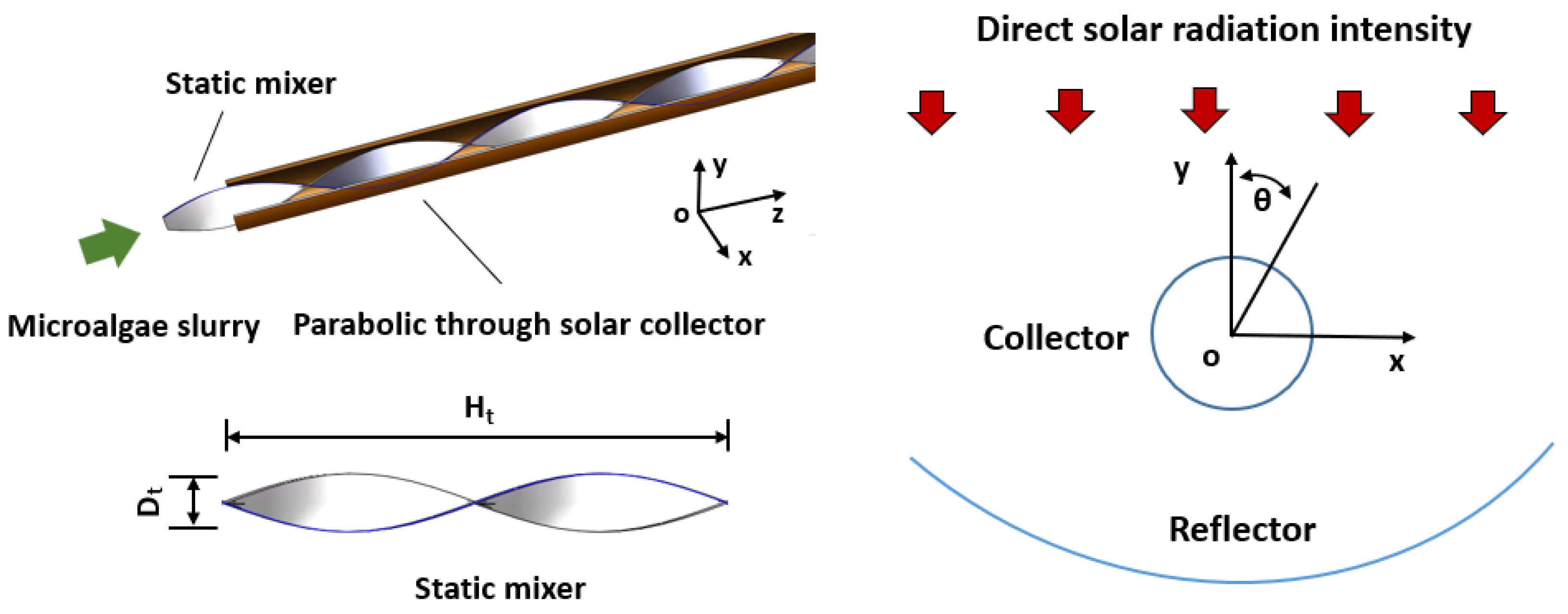
2.1. Physical Condition and Model Assumptions

Figure 1 shows the three-dimensional model of a solar-driven tubular reactor with or without a static mixer. The length (L) of the solar-driven tubular reactor was 6000 mm. The outer diameter and inner diameter of the solar-driven tubular reactor were 38 mm and 32 mm, respectively. The length (L) and the width (w) of the parabolic trough solar reflector were 6000 mm and 2550 mm, respectively. The specular reflectance, transmission of the glass tube and absorptance of the collector were 0.93, 0.915 and 0.95, respectively. In this case, the direct solar radiation intensity was set as 650, 750 and 850 W/m2, while the corresponding non-uniform heat flux q on the outer wall of the solar-driven tubular reactor can be expressed as Equation (1), Equation (2) and Equation (3), respectively [24].
q 650 W / m 2 = 1734.9 x 2 + 41930 x 222688 0 ° θ 130 ° 65.584 x 2 + 1804.3 x + 17429 130 ° < θ 180 ° 65.584 x 2 1804.3 x + 17429 180 ° < θ 230 ° 1734.9 x 2 41930 x 222688 230 ° < θ 360 °
q 750 W / m 2 = 2001.8 x 2 + 48380 x 256946 0 ° θ 130 ° 81.652 x 2 + 2139.2 x + 20031 130 ° < θ 180 ° 81.652 x 2 2139.2 x + 20031 180 ° < θ 230 ° 2001.8 x 2 48380 x 256946 230 ° < θ 360 °
q 850 W / m 2 = 2268.8 x 2 + 54831 x 291206 0 ° θ 130 ° 92.539 x 2 + 2424.5 x + 22702 130 ° < θ 180 ° 92.539 x 2 2424.5 x + 22702 180 ° < θ 230 ° 2268.8 x 2 54831 x 291206 230 ° < θ 360 °
where the corresponding x-axis coordinate value x (m) is calculated as follows:
x = 16 sin θ π / 180 °
where θ is the angle of the solar-driven tubular reactor.
The static mixers inserted in the solar-driven tubular reactor have a series of twist ratios (Y = Ht/Dt = 3, 4, 6, 10), which represent the relationship between the axial distance of the static mixer (Ht) and the width of the static mixer (Dt) (shown in Figure 1). According to the twist ratio of static mixers, the static mixers were labeled as SM-3, SM-4, SM-6 and SM-10, respectively. The thickness (δ) and the width (Dt) of the static mixer were 1 mm and 28 mm, respectively.
In the continuous HTL of microalgae biomass, algal slurry was continuously flowing through the solar-driven tubular reactor with or without the static mixer. Meanwhile, the algal slurry flow through the solar-driven reactor absorbs the non-uniform heat supplied from the parabolic trough solar reflector. The flow rates of the algal slurry were set as 30, 40, 50, 60, 70, 80 L/h. The inlet temperatures of the algal slurry were set as 300 K. The algal slurry mainly contains microalgae biomass and water, whose mass fraction of microalgae biomass was set as 10 wt.%. The outlet pressure was set as 20 MPa. In general, boundary conditions and the studied parameters are summarized in Table 1.

2.2. Governing Equations

In the current study, a three-dimension model was established. The non-uniform heat flux distribution was applied around the tube, whose distribution pattern obeys Equations (1)–(3). Algal slurry was assumed as an incompressible and homogeneous fluid. With the forced convection and swirl effect, the effect of gravity on the flow process is ignored. Laminar flow pattern was set (Re < 25). There is no boundary slip on the wall of the tubular reactor. Therefore, the governing equations in a steady state were written as follows, respectively [35,36].
ρ u = 0
ρ u u = P + μ u + u T
ρ c p T u = λ T
ρ u w i = D i w i + ρ r i
where wi (i = 0–5) is the mass fraction of protein, carbohydrate, lipid, water-soluble organics, biocrude and gas, respectively:
w i = c i / ρ
where ci (i = 0–5) is the concentration of several components.
In Equations (5)–(8), the density of the algal slurry ρ is expressed as follows:
1 ρ = 1 ρ s ω + 1 ρ f 1 ω
where ω is the mass fraction of dry microalgae (10 wt.%) in the slurry, ρs and ρf are the density of the dry microalgae (1324 kg/m3) and water (kg/m3) [37], respectively.
ρ f = 834.87 + 1.39 T 0.00284 T 2
In Equation (6), the viscosity μ (Pa·s) is expressed as follows:
μ = K γ ˙ n 1
where K is the consistency index of the algal slurry (8.6485 × 10⁻² Pa·sn); n is the rheological index of the algal slurry (0.48).
In Equation (7), the specific heat capacity of the algal slurry cp (kJ·kg−1·K−1) is expressed as follows:
c p = c p , s ω + c p , f 1 ω
where cp,s is the specific heat capacity of the microalgae powder (1.620 kJ·kg−1·K−1); cp,f is the specific heat capacity of the water [37]. According to Equation (13), the value of cp was set as 3.9186 kJ·kg−1·K−1 in this study.
In Equation (7), the thermal conductivity of the algal slurry λ (W·m−1·K−1) is set according to the reference [25].
In Equation (8), the diffusion coefficients of several components Di (i = 0–5) are 1 × 10⁻⁹ m2·s−1 [22]. Based on the HTL kinetics model of microalgae biomass (shown in Figure 2) [22], the reaction rates of all components in the slurry ri (i = 0–5) were calculated by Equations (14)–(19). Nannochloropsis sp. was selected as the studied species. The initial mass fractions of protein, carbohydrate and lipid of microalgae biomass were 5.6 wt.%, 1.3 wt.% and 2.0 wt.%, respectively [38].
r 0 = d w 0 / d t = ( k 1 p + k 2 p ) w 0
r 1 = d w 1 / d t = ( k 1 c + k 2 c ) w 1
r 2 = d w 2 / d t = ( k 1 l + k 2 l ) w 2
r 3 = d w 3 / d t = k 1 p w 0 + k 1 c w 1 + k 1 l w 2 + k 3 w 4 ( k 4 + k 5 ) w 3
r 4 = d w 4 / d t = k 2 p w 0 + k 2 c w 1 + k 2 l w 2 + k 4 w 3 ( k 3 + k 6 ) w 4
r 5 = d w 5 / d t = k 5 w 3 + k 6 w 4
where k0k6 are reaction rate constants (s−1) [16]:
k i = A i e E a / R T

2.3. Numerical Method

In the current simulation, a fluid region and a solid region were included in the numerical model (shown in Figure 3), and the grids of computational regions were created in GAMBIT. The solid region is the area of a circular tube, 3 grids were divided in the radial direction, 50 grids were divided in the circumferential direction and 3000 grids were divided in the radial direction. The fluid region is the area of algal slurry, which represents the cylindrical region of the tube channel except the static mixer. In it, 50 grids were divided in the circumferential direction, 28 grids were divided across the width (Dt) of the static mixer, 1 grid was divided across the thickness (δ) of the static mixer. In the fluid region, 4 progressively increasing hexahedral grids were set for calculating the physical field of velocity, temperature and concentration clearly. The first mesh size was set as 0.1 mm, and mesh size was increased by a multiple of 1.2. In the fluid region, the boundary layer region was divided by hexahedral mesh, and other region was divided by tetrahedral mesh. The total mesh number used in this study was 14,066,514.
In the current simulation, the computational software ANSYS FLUENT was utilized for solving this problem. The governing equations were discretized by the finite volume method (FVM). At a Peclet number of algal slurry between 1870 and 4523, the second-order upwind and central differencing schemes were used to approximate the convective and diffusion terms in the differential equation, respectively. The velocity–pressure coupled equation was solved in the collocated grid by using the SIMPLE algorithm. The residuals were detected to check the convergence. The residuals of the continuity equation and other equations were set as 10−3 and 10−6, respectively.
The flow resistance f is defined as follows:
f = 2 d i l ρ u 2 Δ P
where di is the inner diameter of the solar-driven tubular tube, l is the length of the solar-driven tubular reactor, ΔP is the differential pressure between the inlet and outlet of the solar-driven tubular reactor.
The Nusselt number Nu of the algal slurry in the solar-driven reactor is expressed as:
N u = h d i λ
where h is the convective heat transfer coefficient (W·m−2·k−1):
h = Q A Δ T m
Q is the heat flux (W):
Q = m c p T o u t T i n
The mean temperature difference (ΔTm) between the inner wall of the reactor and algal slurry is expressed as follows:
Δ T m = T w T f
where Tw is the average temperature of the tube wall, Tf is the mean temperature of fluid in the solar-driven tubular reactor.
The heat transfer enhancement factor PEC is expressed as follows:
PEC = N u / N u 0 / f / f 0 1 / 3
The yields of the organics Yi are represented as follows:
Y i = w i , o u t w i , i n ω
where wi is the mean mass fraction of organics at the inlet and outlet of the tube.
The conversion rates of components are represented as follows:
R i = ρ w i , o u t w i , i n L / u m
The Reynolds number Re is defined as:
R e = ρ u m L H / μ
where LH is the hydraulic length:
L H = d i 4 A D / χ

3. Results and Discussion

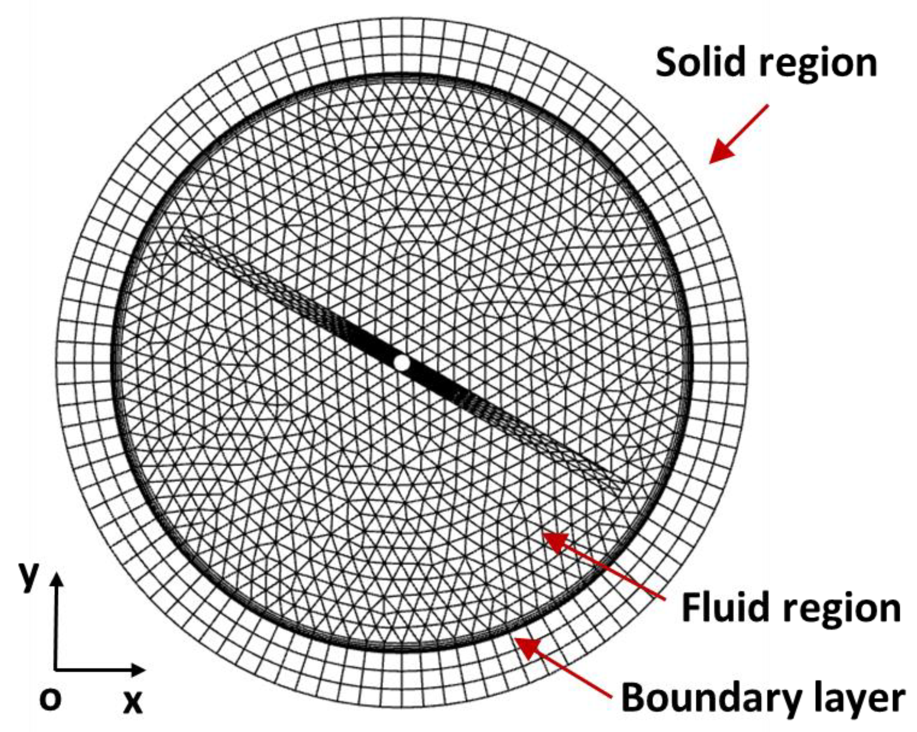
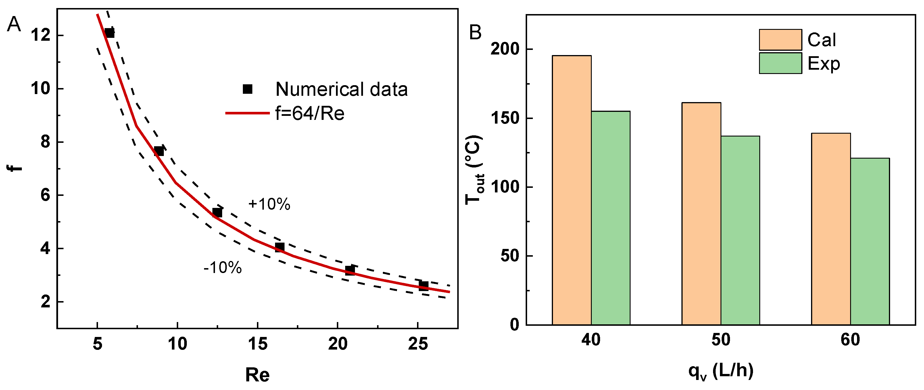
3.1. Grid Independence and Model Validation

The grid independence has been validated in the case of a solar-driven tubular reactor with a static mixer with a twist ratio of 4. The test case was set at the flow rate of 60 L/h and the direct solar radiation intensity of 750 W/m2. In Table 2, the convective heat transfer coefficient h, pressure drop ΔP and biocrude yield YBC have been compared under the same model with four meshes (7.6, 10.2, 14.1, 26.1 million). In addition, the detailed line grids are listed in Table 3.
The validated results show that all cases have a similar ΔP, whose ΔP error is below 1.06%. Comparing the h of No.1 and No.2 to No.3, the h errors were 41.88% and 15.05%. Additionally, the h error between the results of 7,642,715 grids and 10,239,632 grids is 5.65%, whose error was below 10%. The lowest biocrude yield YBC error was also calculated in the meshes between No.3 and No.4. Thus, the model with 14.1 million grids was selected in this simulation.
The reliability of the numerical results of flow resistance, heat transfer and HTL conversion were compared to experiment data. The flow resistance of microalgae in cold conditions obeys the Darcy friction factor [39,40]. The difference between the numerical data and theoretical value was under 10% (Figure 4A). The outlet temperature of algal slurry obtained by experimental data and numerical data was compared to validate the heat transfer. The calculated outlet temperatures of algal slurry in a plain solar-driven reactor were compared with experimental data at 40, 50 and 60 L/h [17], whose errors were 26%, 17.7% and 15%, respectively (Figure 4B). In addition, the reliability of the numerical procedure for simulating the HTL of algal biomass in a continuous reactor has been validated in a previous investigation [24]. The outlet concentration of biocrude obtained by experimental data and numerical data was compared to validate the products from the hydrothermal process.

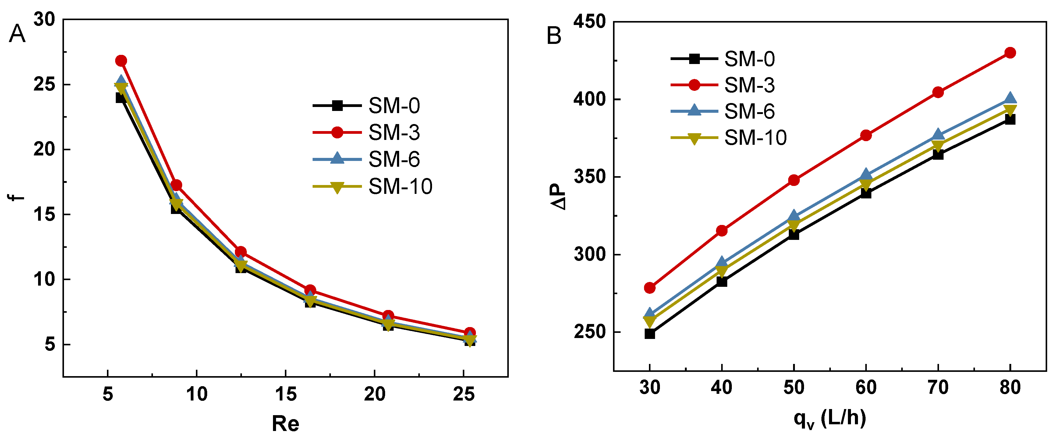
3.2. Flow Resistance of Algal Slurry in the Reactor with Static Mixer

Figure 5A shows the friction factor of the algal slurry flow through the solar-driven reactor with various static mixers, whose twist ratio of the static swirls ranged from 0 to 10. The friction factor of the microalgae flow through the solar-driven reactor significantly decreased with the increasing Re from 5 to 25. At a certain Re, the friction factor of SM-3 was slightly higher than that of SM-6, SM-10 and SM-0. This phenomenon revealed that the friction-loss-inducing static mixer inserted in the solar-driven reactor was acceptable.
Figure 5B shows the pressure drop of the algal slurry in the solar-driven reactor with various static mixers. The pressure drop obviously increased with the increasing flow rate from 30 to 80 L/h. Thus, flow rate was a key influence factor on the pressure drop in the solar-driven reactor. Additionally, the pressure drop was decreased with the twist ratio from 3 to 10. For instance, the pressure drop in SM-3 (376 Pa) was 1.07, 1.09 times that in SM-6 and SM-10 at the flow rate of 60 L/h, respectively. The results indicated that the static mixer with low twist tape was able to induce a stronger swirling effect, promoting the pressure drop of the algal slurry flow through the solar-driven reactor. Contour plots of average velocity of the algal slurry in SM-0 and SM-3 at 60 L/h are shown in Figure 6.

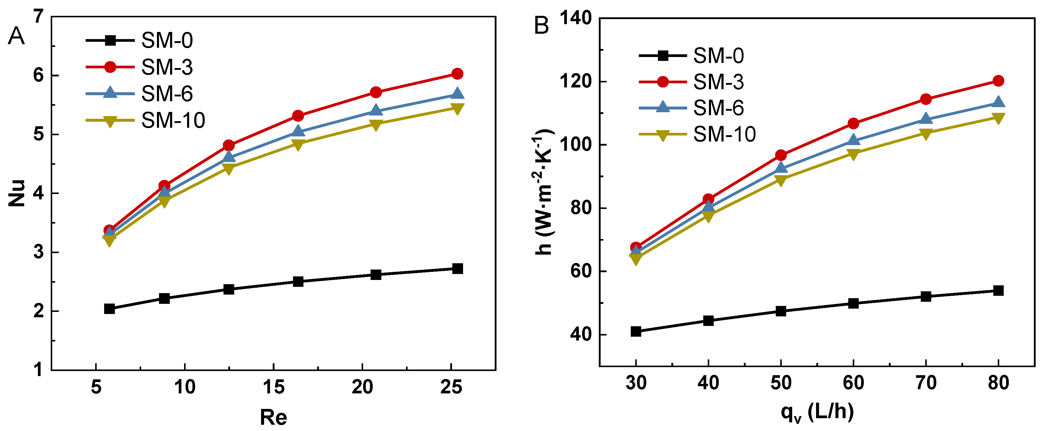
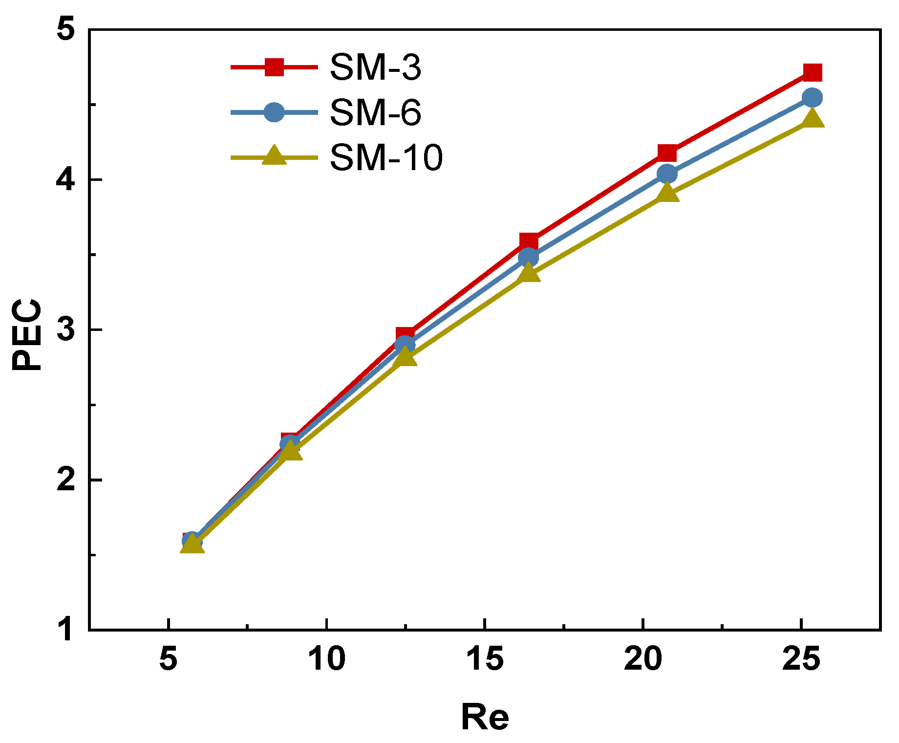
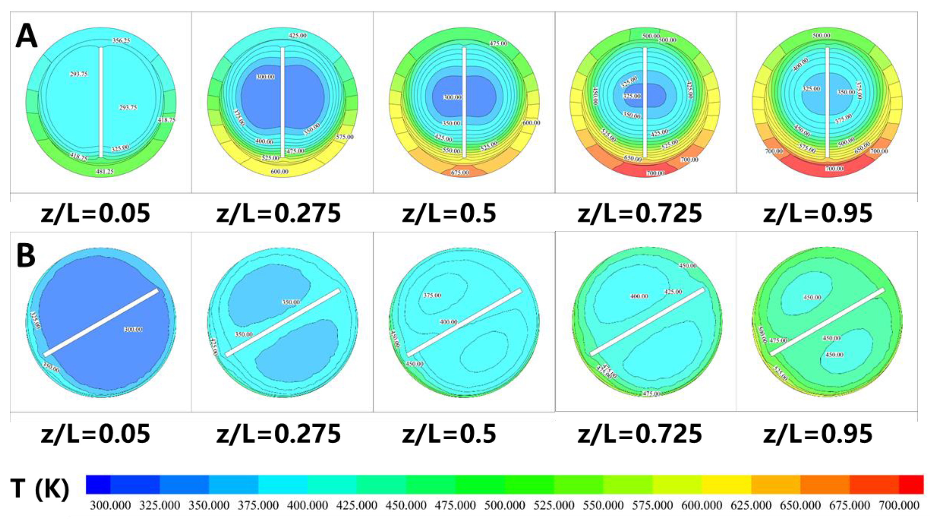
3.3. Heat Transfer Enhancement of Algal Slurry by Static Mixer

Figure 7A shows that the Nu of the algal slurry increased with the increase in Re from 5 to 25. Particularly, the growth slope of Nu in the solar-driven reactor with a static mixer was obviously higher than that of the solar-driven reactor without a static mixer. For instance, the Nu increased from 2.04 to 2.72 with the Re from 5 to 25 in SM-0, while the Nu increased from 3.37 to 6.03 with the Re from 5 to 25 in SM-3. It indicated that the swirl effect induced by the static mixer was enhanced by the increasing flow rate. In addition, the Nu of the algal slurry in the solar-driven reactor decreased with the increasing twist ratio of the static mixer at a certain Re. For example, the Nu of SM-3, SM-6 and SM-10 were 6.03, 5.67 and 5.45 at the Re of 25, respectively.
Figure 7B shows the h increased with the increasing Re from 5 to 25. At a certain flow rate, the h of the solar-driven reactor with a static mixer was significantly higher than that of the solar-driven reactor without a static mixer. For example, the h of the algal slurry in SM-3 (97 W·m−2·K−1) was 2.06 times that of SM-0 (47 W·m−2·K−1) at the flow rate of 50 L/h. It indicated that the swirling effect induced by the static mixer obviously enhanced the heat transfer performance of the algal slurry in the solar-driven reactor, while the swirling effect was enhanced by the increased of flow rate. In addition, the maximum h was observed in the solar-driven reactor with SM-3. For example, the h in SM-3 (120 W·m−2·K−1) was 1.06 and 1.10 times that of SM-6 and SM-10 at 80 L/h, respectively.
Figure 8 shows the variation of comprehensive heat transfer performance (PEC) with the increasing Re. It can be observed that the PEC significantly increased when the Re increased from 5 to 25. For example, the PEC of SM-3 increased from 1.59 to 4.71, implying that the static mixer inserted in the solar-driven reactor has a desired effect in the heat transfer enhancement. Figure 9 shows temperature distribution of the algal slurry and in SM-0 and SM-3 at 60 L/h. The temperature distribution of the algal slurries in SM-3 was more uniform than that of SM-0. Therefore, the static mixer was regarded as ideal equipment to enhance the heat transfer in the solar-driven tubular reactor.

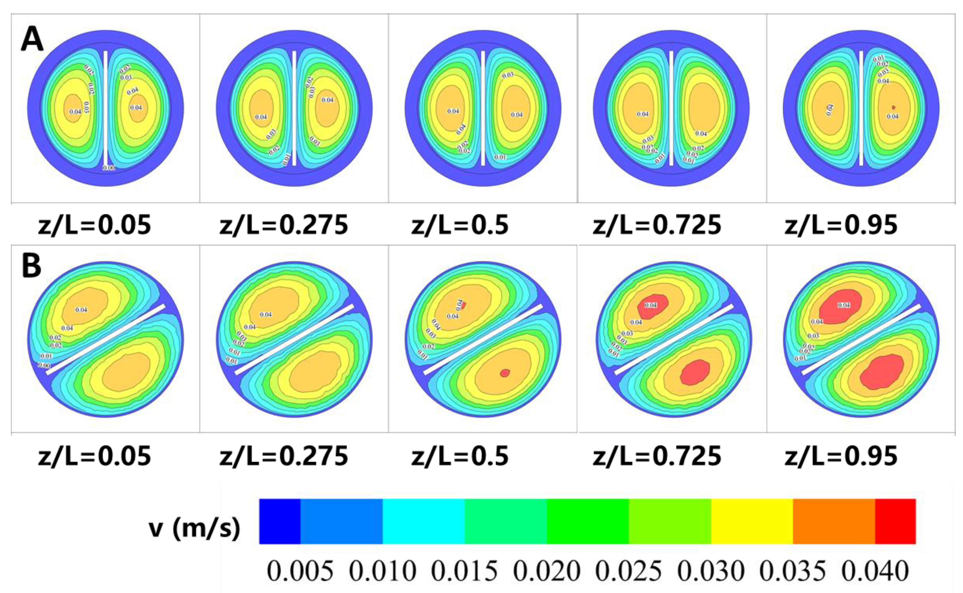
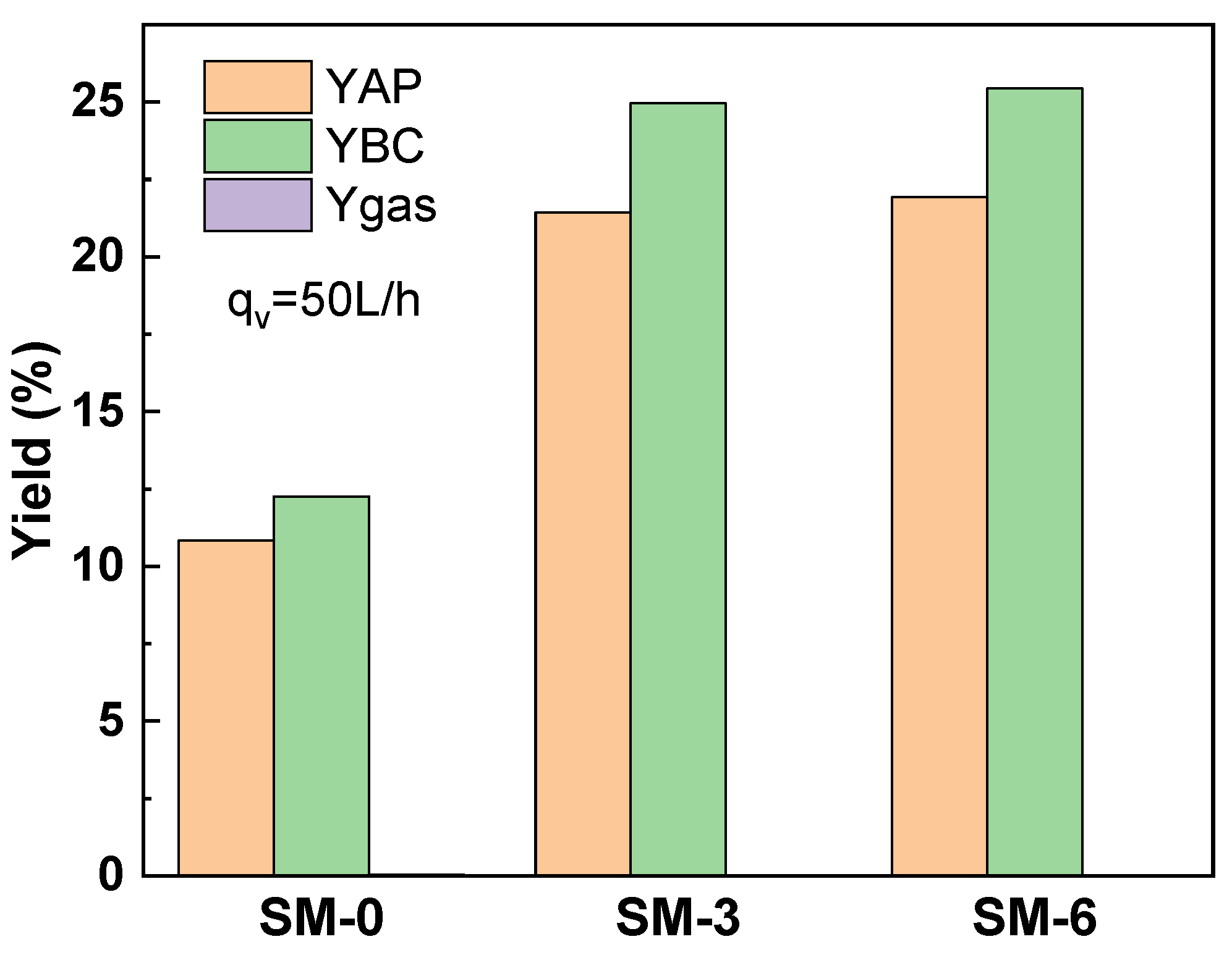
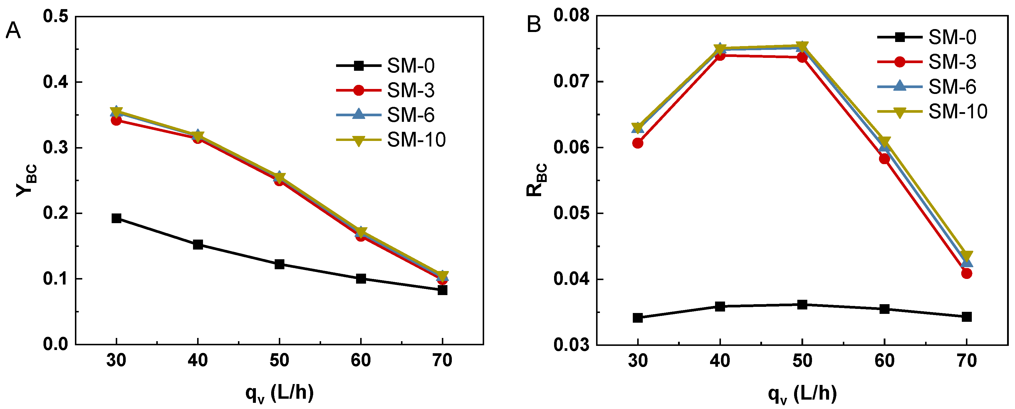
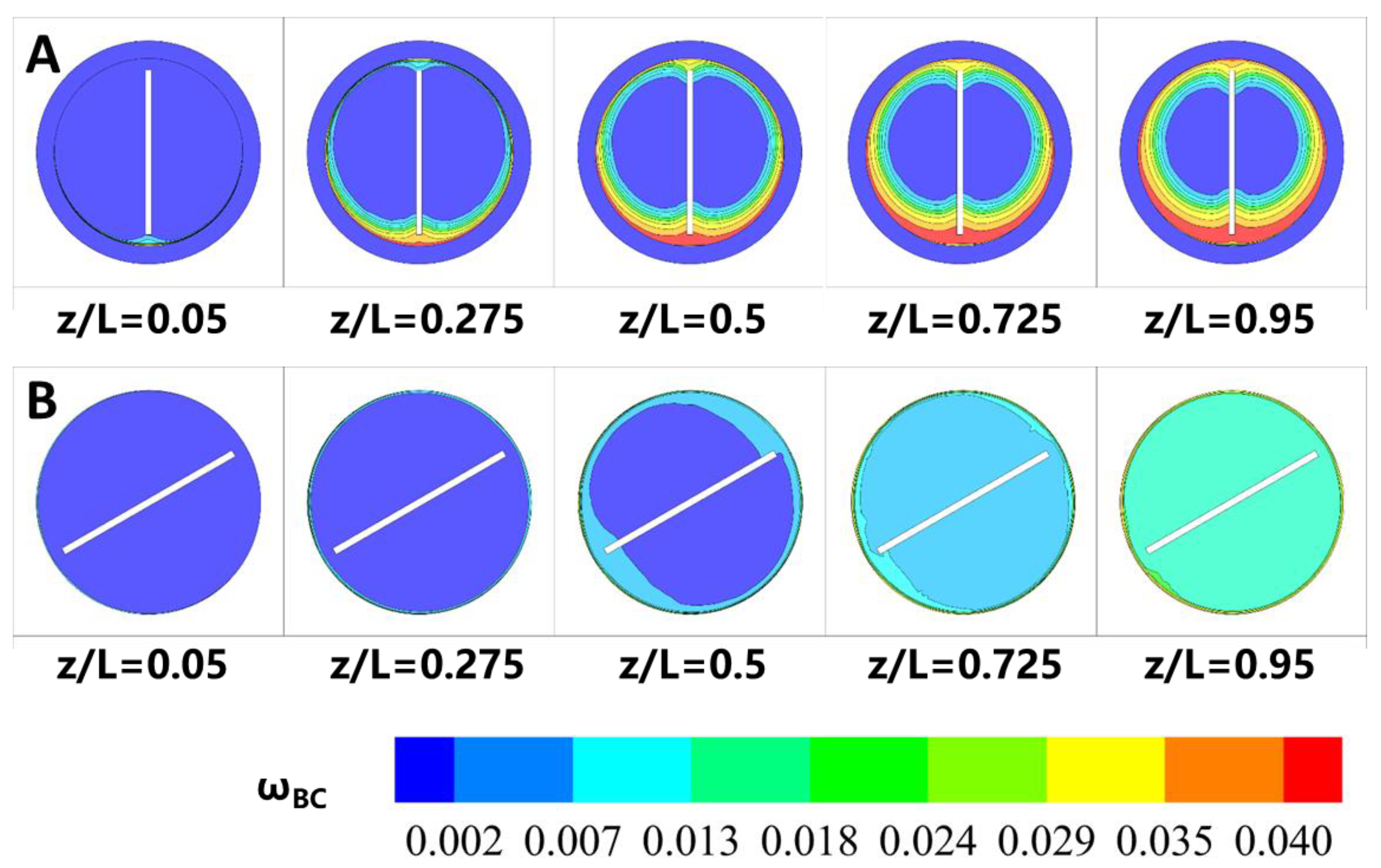
3.4. Effect of Swirl Flow Induced by Static Mixer on HTL of Microalgae Biomass

The static mixer installed in the solar-driven reactor not only promotes the heat transfer of algal slurry but also promotes the production of HTL products. Figure 10 shows the yield of water-soluble organics, biocrude and biogas by the solar-driven reactor in SM-0, SM-3 and SM-6, respectively. Compared to the yield of aqueous organics (21.4%) and biocrude (25.0%), the biogas yield (7.81 × 10⁻⁴%) was negligible.
Figure 11A shows the biocrude yield of the reaction fluid at the outlet section in SM-0, SM-3, SM-6 and SM-10 (30–70 L/h) and the direct solar radiation intensity of 750 W/m2. The biocrude yields in solar-driven reactors with static mixers were higher than that in SM-0. For example, the biocrude yield in SM-3 (25%) was 2.03 times that in SM-0 (12.3%) at the flow rate of 50 L/h. These results are attributed to the uniform temperature distribution and mass distribution in the solar-driven reactor, which was caused by the swirl effect, shown in Figure 9 and Figure 12. Figure 11B shows the formation rate of organics was promoted at the low flow rate. The maximum formation rate of biocrude (0.074 g·L−1·s−1) appeared in the flow rate of 50 L/h. It shows that the swirl effect promoted the production of HTL products in the region of low flow rate through the enhancement of heat transfer. And then, the reduction of temperature limited the production of HTL products in the region of high flow rate.

3.5. Effect of Solar Radiation on the HTL in Solar-Driven Reactor

Figure 13 shows the yields of water-soluble organics, biocrude and biogas by the solar-driven reactor at 650, 750 and 850 W/m2, respectively. Owing to the photothermal transformation, the yields of water-soluble organics and biocrude increased with the increase in direct solar radiation from 650 to 850 W/m2. The variations of the biocrude yield under various direct solar radiation levels (650, 750, 850 W/m2) have been shown in Figure 14A. Figure 14B shows the RBC increased with the direct solar radiation from 650 to 850 W/m2. The formation rate of biocrude at 850 W/m2 and 50 L/h (0.091 g·L−1·s−1) was 1.44 and 1.14 times that of 650 and 750 W/m2, respectively. At 750 and 850 W/m2, the optimal conversion rate of biocrude occurred at 50 L/h, whose values were 7.97 and 9.12 g·L−1·s−1, respectively. At 650 W/m2, the optimal formation rate was 7.33 g·L−1·s−1 at 40 L/h. This phenomenon indicated that high thermal energy input guaranteed the high formation rate of algal biomass in the solar-driven reactor.

4. Conclusions

In this investigation, the flow, heat transfer and HTL of algal slurry flow through a parabolic solar collector with static mixers (5 < Re < 25) were studied. A CFD model combining HTL kinetics and non-uniform heat boundary conditions was established. The static mixer in the solar-driven reactor can cause circumferential flow, significantly increasing the h from 47 to 97 W·m2·K1. The static mixer with the twist ratio of 3 (SM-3) had the highest PEC. In the solar-driven reactor, the aqueous organics and biocrude were the main products, and the production of biogas can be ignored. Particularly, the formation rate of organics was dependent on the outlet temperature and the uniformity of the temperature distribution. The RBC was firstly enhanced by the swirl effect and convective effect below 50 L/h but reduced by temperature at the higher flow rate.

Author Contributions

Writing—original draft preparation, H.C.; Writing—review and editing, F.L.; Project administration, H.C.; Resources, X.Z.; Validation, C.S.; Conceptualization, W.P.; Supervision, S.W. All authors have read and agreed to the published version of the manuscript.

Funding

This research was funded by National Natural Science Foundation of China, 52106091.

Data Availability Statement

The data presented in this study are available on request from the corresponding author.

Conflicts of Interest

The authors declare no conflict of interest.

Nomenclature

Symbols
AHeat transfer area (m2)
AiArrhenius constant (s−1)
cpSpecific heat capacity (kJ·kg−1·K−1)
DDiffusivities of all species (m2·s−1)
dDiameter of tube (m)
EaActivation energy (kJ·mol−1)
fFlow resistance
hConvective heat transfer coefficient (W·m−2·K−1)
kReaction rate constant (s−1)
LLength of the tube (m)
NuNusselt number
PPressure (Pa)
PePeclet number
PECHeat transfer enhancement factor
qHeat flux (W/m2)
RGas constant (J·mol−1·K−1)
RiConversion rate of organics (g·L−1·s−1)
ReReynolds number
rReaction rates of organics (g·L−1·s−1)
TTemperature (K)
ΔTmMean temperature difference (K)
tResidence time (s)
uVelocity (m·s−1)
umAverage velocity (m·s−1)
wMass fraction of organics
YThe yield of organics
xX-direction distance of the tube (m)
yY-direction distance of the tube (m)
zAxial position of the tube (m)
Greek symbols
ρDensity (kg·m−3)
λThermal conductivity (W·m−1·K−1)
μViscosity (Pa·s)
ωMass fraction of microalgae biomass
γShear rate (s−1)
Subscripts
BCBiocrude
fLiquid phase
iNumber of organics in HTL pathways
inInlet
outOutlet
sSolid phase
wTube wall

References

  1. Elliott, D.C.; Biller, P.; Ross, A.B.; Schmidt, A.J.; Jones, S.B. Hydrothermal liquefaction of biomass: Developments from batch to continuous process. Bioresour. Technol. 2015, 178, 147–156. [Google Scholar] [CrossRef] [PubMed]
  2. Hoang, A.T.; Ong, H.C.; Fattah, I.M.R.; Chong, C.T.; Cheng, C.K.; Sakthivel, R.; Ok, Y.S. Progress on the lignocellulosic biomass pyrolysis for biofuel production toward environmental sustainability. Fuel Process. Technol. 2021, 223, 106997. [Google Scholar] [CrossRef]
  3. Li, S.; Li, X.; Ho, S.H. Microalgae as a solution of third world energy crisis for biofuels production from wastewater toward carbon neutrality: An updated review. Chemosphere 2022, 291 Pt 1, 132863. [Google Scholar] [CrossRef] [PubMed]
  4. Cronin, D.; Schmidt, A.J.; Billing, J.; Hart, T.R.; Fox, S.P.; Fonoll, X.; Norton, J.; Thorson, M.R. Comparative Study on the Continuous Flow Hydrothermal Liquefaction of Various Wet-Waste Feedstock Types. ACS Sustain. Chem. Eng. 2021, 10, 1256–1266. [Google Scholar] [CrossRef]
  5. Chen, H.; Xia, A.; Zhu, X.; Huang, Y.; Zhu, X.; Liao, Q. Hydrothermal hydrolysis of algal biomass for biofuels production: A review. Bioresour. Technol. 2022, 344 Pt B, 126213. [Google Scholar] [CrossRef]
  6. Chen, W.-H.; Lin, B.-J.; Huang, M.-Y.; Chang, J.-S. Thermochemical conversion of microalgal biomass into biofuels: A review. Bioresour. Technol. 2015, 184, 314–327. [Google Scholar] [CrossRef] [PubMed]
  7. Osman, A.I.; Mehta, N.; Elgarahy, A.M.; Al-Hinai, A.; Al-Muhtaseb, A.A.H.; Rooney, D.W. Conversion of biomass to biofuels and life cycle assessment: A review. Environ. Chem. Lett. 2021, 19, 4075–4118. [Google Scholar] [CrossRef]
  8. Gollakota, A.; Savage, P.E. Fast and Isothermal Hydrothermal Liquefaction of Polysaccharide Feedstocks. ACS Sustain. Chem. Eng. 2020, 8, 3762–3772. [Google Scholar] [CrossRef]
  9. Ghavami, N.; Özdenkçi, K.; Chianese, S.; Musmarra, D.; De Blasio, C. Process simulation of hydrothermal carbonization of digestate from energetic perspectives in Aspen Plus. Energy Convers. Manag. 2022, 270, 116215. [Google Scholar] [CrossRef]
  10. Liu, H.; Basar, I.A.; Eskicioglu, C. Hydrothermal liquefaction for sludge-to-energy conversion: An evaluation of biocrude production and management of waste streams. Energy 2023, 281, 128268. [Google Scholar] [CrossRef]
  11. Liu, H.; Zhu, Y.; Yang, W.; Li, Y.; Yang, H.; Chen, Y.; Wang, X.; Chen, H. Valorization of the microalgae fixing CO2 from flue gas by co-hydrothermal liquefaction with high-protein microalgae: Denitrogenation of bio-oil by ash and high energy recovery. Fuel 2023, 340, 127566. [Google Scholar] [CrossRef]
  12. Ağbulut, Ü.; Sirohi, R.; Lichtfouse, E.; Chen, W.-H.; Len, C.; Show, P.L.; Le, A.T.; Nguyen, X.P.; Hoang, A.T. Microalgae bio-oil production by pyrolysis and hydrothermal liquefaction: Mechanism and characteristics. Bioresour. Technol. 2023, 376, 128860. [Google Scholar] [CrossRef]
  13. Cheng, F.; Cui, Z.; Mallick, K.; Nirmalakhandan, N.; Brewer, C.E. Hydrothermal liquefaction of high- and low-lipid algae: Mass and energy balances. Bioresour. Technol. 2018, 258, 158–167. [Google Scholar] [CrossRef]
  14. Ayala-Cortés, A.; Arcelus-Arrillaga, P.; Millan, M.; Arancibia-Bulnes, C.A.; Valadés-Pelayo, P.J.; Villafán-Vidales, H.I. Solar integrated hydrothermal processes: A review. Renew. Sustain. Energy Rev. 2021, 139, 110575. [Google Scholar] [CrossRef]
  15. Ayala-Cortés, A.; Arcelus-Arrillaga, P.; Millan, M.; Okoye, P.U.; Arancibia-Bulnes, C.A.; Pacheco-Catalán, D.E.; Villafán-Vidales, H.I. Solar hydrothermal processing of agave bagasse: Insights on the effect of operational parameters. Renew. Energy 2022, 192, 14–23. [Google Scholar] [CrossRef]
  16. Sheehan, J.D.; Savage, P.E. Modeling the effects of microalga biochemical content on the kinetics and biocrude yields from hydrothermal liquefaction. Bioresour. Technol. 2017, 239, 144–150. [Google Scholar] [CrossRef]
  17. Xiao, C.; Liao, Q.; Fu, Q.; Huang, Y.; Chen, H.; Zhang, H.; Xia, A.; Zhu, X.; Reungsang, A.; Liu, Z. A solar-driven continuous hydrothermal pretreatment system for biomethane production from microalgae biomass. Appl. Energy 2019, 236, 1011–1018. [Google Scholar] [CrossRef]
  18. Ischia, G.; Orlandi, M.; Fendrich, M.A.; Bettonte, M.; Merzari, F.; Miotello, A.; Fiori, L. Realization of a solar hydrothermal carbonization reactor: A zero-energy technology for waste biomass valorization. J. Environ. Manag. 2020, 259, 110067. [Google Scholar] [CrossRef]
  19. Giaconia, A.; Turchetti, L.; Ienna, A.; Mazzei, D.; Schiavo, B.; Scialdone, O.; Caputo, G.; Galia, A. Conceptual study of the coupling of a biorefinery process for hydrothermal liquefaction of microalgae with a concentrating solar power plant. In AIP Conference Proceedings; AIP Publishing: New York, NY, USA, 2017. [Google Scholar]
  20. Narvaez Saucedo, M.E.; Arancibia-Bulnes, C.A.; Macias, J.D.; Ramirez-Cabrera, M.A.; Valades-Pelayo, P.J. Heat transfer and chemical kinetics analysis of a novel solar reactor for hydrothermal processing. Solar Energy 2022, 241, 372–385. [Google Scholar] [CrossRef]
  21. Briongos, J.V.; Taramona, S.; Gómez-Hernández, J.; Mulone, V.; Santana, D. Solar and biomass hybridization through hydrothermal carbonization. Renew. Energy 2021, 177, 268–279. [Google Scholar] [CrossRef]
  22. Ranganathan, P.; Savithri, S. Computational Fluid Dynamics simulation of hydrothermal liquefaction of microalgae in a continuous plug-flow reactor. Bioresour. Technol. 2018, 258, 151–157. [Google Scholar] [CrossRef]
  23. Xiao, C.; Liao, Q.; Fu, Q.; Huang, Y.; Xia, A.; Chen, H.; Zhu, X. Numerical investigation of laminar mixed convection of microalgae slurry flowing in a solar collector. Appl. Therm. Eng. 2020, 175, 115366. [Google Scholar] [CrossRef]
  24. Chen, H.; Zhang, X.; Fan, X.; Li, Z.; Qian, L.; Zhang, B.; Wang, S. Convective enhancement of microalgae slurry in continuous tubular reactors for biocrude production during hydrothermal liquefaction. Appl. Therm. Eng. 2023, 220, 119725. [Google Scholar] [CrossRef]
  25. Chen, H.; Liao, Q.; Fu, Q.; Huang, Y.; Xia, A.; Xiao, C.; Zhu, X. Convective heat transfer characteristics of microalgae slurries in a circular tube flow. Int. J. Heat Mass Transfer 2019, 137, 823–834. [Google Scholar] [CrossRef]
  26. Chu, W.-X.; Tsai, C.-A.; Lee, B.-H.; Cheng, K.-Y.; Wang, C.-C. Experimental investigation on heat transfer enhancement with twisted tape having various V-cut configurations. Appl. Therm. Eng. 2020, 172, 115148. [Google Scholar] [CrossRef]
  27. Taheran, E.; Javaherdeh, K. Experimental investigation on the effect of inlet swirl generator on heat transfer and pressure drop of non-Newtonian nanofluid. Appl. Therm. Eng. 2019, 147, 551–561. [Google Scholar] [CrossRef]
  28. Klemeš, J.J.; Wang, Q.-W.; Varbanov, P.S.; Zeng, M.; Chin, H.H.; Lal, N.S.; Li, N.-Q.; Wang, B.; Wang, X.-C.; Walmsley, T.G. Heat transfer enhancement, intensification and optimisation in heat exchanger network retrofit and operation. Renew. Sust. Energy Rev. 2020, 120, 109644. [Google Scholar] [CrossRef]
  29. Feng, Z.; Ai, X.; Wu, P.; Lin, Q.; Huang, Z. Experimental investigation of laminar flow and heat transfer characteristics in square minichannels with twisted tapes. Int. J. Heat Mass Transf. 2020, 158, 119947. [Google Scholar] [CrossRef]
  30. Chen, H.; Fu, Q.; Liao, Q.; Zhang, H.; Huang, Y.; Xia, A.; Zhu, X. Rheological properties of microalgae slurry for application in hydrothermal pretreatment systems. Bioresour. Technol. 2018, 249, 599–604. [Google Scholar] [CrossRef]
  31. Singh, S.K.; Kacker, R.; Chaurasiya, P.K.; Gautam, S.S. Correlations on heat transfer rate and friction factor of a rectangular toothed v-cut twisted tape exhibiting the combined effects of primary and secondary vortex flows. Int. Commun. Heat Mass Transf. 2022, 139, 106503. [Google Scholar] [CrossRef]
  32. Varun; Garg, M.O.; Nautiyal, H.; Khurana, S.; Shukla, M.K. Heat transfer augmentation using twisted tape inserts: A review. Renew. Sustain. Energy Rev. 2016, 63, 193–225. [Google Scholar] [CrossRef]
  33. Maluta, F.; Paglianti, A.; Montante, G. A PBM-Based Procedure for the CFD Simulation of Gas–Liquid Mixing with Compact Inline Static Mixers in Pipelines. Processes 2023, 11, 198. [Google Scholar] [CrossRef]
  34. Cao, Q.; Zhou, J.; Qian, Y.; Yang, S. Three-Dimensional Model on Liquid–Liquid Mass Transfer of the Kenics Static Mixer: Considering Dynamic Droplet Size Distribution. Ind. Eng. Chem. Res. 2023, 62, 10507–10522. [Google Scholar] [CrossRef]
  35. Mahian, O.; Kolsi, L.; Amani, M.; Estellé, P.; Ahmadi, G.; Kleinstreuer, C.; Marshall, J.S.; Siavashi, M.; Taylor, R.A.; Niazmand, H.; et al. Recent advances in modeling and simulation of nanofluid—Part I: Fundamentals and theory. Phys. Rep. 2019, 790, 1–48. [Google Scholar] [CrossRef]
  36. Mahian, O.; Kolsi, L.; Amani, M.; Estellé, P.; Ahmadi, G.; Kleinstreuer, C.; Marshall, J.S.; Taylor, R.A.; Abu-Nada, E.; Rashidi, S.; et al. Recent advances in modeling and simulation of nanofluid flows—Part II: Applications. Phys. Rep. 2019, 791, 1–59. [Google Scholar] [CrossRef]
  37. Wagner, W.; Kretzschmar, H. International Steam Tables-Properties of Water and Steam Based on the Industrial Formulation IAPWS-IF97: Tables, Algorithms, Diagrams, and CD-ROM Electronic Steam Tables-All of the Equations of IAPWS-IF97 Including a Complete Set of Supplementary Backward Equations for Fast Calculations of Heat Cycles, Boilers, and Steam Turbines; Springer Science & Business Media: Berlin, Germany, 2007. [Google Scholar]
  38. Valdez, P.J.; Tocco, V.J.; Savage, P.E. A general kinetic model for the hydrothermal liquefaction of microalgae. Bioresour. Technol. 2014, 163, 123–127. [Google Scholar] [CrossRef]
  39. Brown, T.M.; Duan, P.; Savage, P.E. Hydrothermal Liquefaction and Gasification of Nannochloropsis sp. Energy Fuels 2010, 24, 3639–3646. [Google Scholar] [CrossRef]
  40. Chhabra, R.P.; Richardson, J.F. Non-Newtonian Flow in the Process Industries; Butterworth-Heinemann: Oxford, UK, 1999; pp. 147–158. [Google Scholar]
Figure 1. Schemes of parabolic trough solar-driven reactor with static mixer.
Energies 16 07986 g001
Figure 2. Reaction pathways for HTL of microalgae biomass [38].
Energies 16 07986 g002
Figure 3. Grid of the solar-driven reactor with static mixer in cross-section.
Energies 16 07986 g003
Figure 4. (A) Friction factor and (B) outlet temperature of algal slurry in a plain solar-driven reactor with various static mixers.
Energies 16 07986 g004
Figure 5. (A) Friction factor and (B) pressure drop of algal slurry in solar-driven reactor with various static mixers.
Energies 16 07986 g005
Figure 6. (A) Average velocity distribution of the algal slurry in (A) SM-0 and (B) SM-3 at 60 L/h.
Energies 16 07986 g006
Figure 7. (A) Nu and (B) h of algal slurry flow through solar-driven reactor with various static mixers.
Energies 16 07986 g007
Figure 8. Comprehensive heat transfer performance of solar-driven reactor with inserted static mixers.
Energies 16 07986 g008
Figure 9. Temperature distribution of the flow cross-section in (A) SM-0 and (B) SM-3 at 60 L/h.
Energies 16 07986 g009
Figure 10. The yield of water-soluble organics, biocrude and biogas in solar-driven reactor with different static mixers.
Energies 16 07986 g010
Figure 11. Effect of the static mixer on the (A) YBC and (B) RBC in solar-driven reactor.
Energies 16 07986 g011
Figure 12. Mass fraction distribution of the flow cross-section in (A) SM-0 and (B) SM-3 at 60 L/h.
Energies 16 07986 g012
Figure 13. The yield of water-soluble organics, biocrude and biogas in solar-driven reactor with different direct solar radiation levels.
Energies 16 07986 g013
Figure 14. Effect of solar radiation on the (A) YBC and (B) RBC in SM-3.
Energies 16 07986 g014
Table 1. Boundary conditions and the studied parameters.
Boundary ConditionValue
Flow rate at the inlet30, 40, 50, 60, 70, 80 L/h
Mean temperature at the inlet300 K
Pressure at the outlet20 MPa
Direct solar radiation intensity650, 750 and 850 W/m2
Heat flux at the wallEquation (1), Equation (2), Equation (3)
Studied parametersf, Nu, PEC, Re, yield of water-soluble organics, biocrude, biogas, formation rate of biocrude
Table 2. Grid independence of research models.
Grid NumberΔP
(Pa)
ΔP Error
(%)
h (W·m−2·k−1)h Error (%)YBCYBC Error (%)
7642715358.2−1.06%150.841.88%14.7%−15.84%
10239632361.0−0.28%122.315.05%16.2%−7.23%
14066514362.0Baseline106.3Baseline17.4%Baseline
26082444363.50.42%112.35.65%18.5%6.29%
Table 3. Grid meshing of lines in the model of solar-driven tubular reactor.
MeshlCδDt
No.1 (7,642,715)200040120
No.2 (10,239,632)240050128
No.3 (14,066,514)300050128
No.4 (26,082,444)400060128
Disclaimer/Publisher’s Note: The statements, opinions and data contained in all publications are solely those of the individual author(s) and contributor(s) and not of MDPI and/or the editor(s). MDPI and/or the editor(s) disclaim responsibility for any injury to people or property resulting from any ideas, methods, instructions or products referred to in the content.

