Article

Axial Flux Permanent Magnet Motor Topologies Magnetic Performance Comparison

1
Department of Mechanical Engineering, University of Bath, Bath BA2 7AY, UK
2
Department of Electronic and Electrical Engineering, University of Bath, Bath BA2 7AY, UK
*
Author to whom correspondence should be addressed.
Energies 2024, 17(2), 401; https://doi.org/10.3390/en17020401
Submission received: 9 December 2023 / Revised: 10 January 2024 / Accepted: 11 January 2024 / Published: 13 January 2024
(This article belongs to the Topic Advanced Electrical Machine Design and Optimization Ⅱ)

Abstract

:
Axial flux permanent magnet motors have attracted increasing attention due to their compact topology and high torque density. Many topological variations have arisen over time; however, limited research has directly compared the differences in magnetic performance of these topologies. This paper carries out a comprehensive investigation, employing both analytical and 3D finite element analyses, to compare the magnetic performance of three topologies: yokeless and segmented armature (YASA), axial flux internal rotor (AFIR), and offset AFIR. The findings reveal that each topology offers specific advantages for different applications. The YASA topology excels in minimizing core losses; the AFIR configuration achieves the highest torque density; and the offset AFIR topology shows the highest efficiency. The offset AFIR topology appears to offer advantages for a wide array of applications due to its higher power factor and lower permanent magnet loss, leading to reduced costs for converter design and cooling system design.

1. Introduction

The use of axial flux excitation in motor operation can be traced back to the pioneering work of Faraday in 1831 [1]. The axial flux permanent magnet (AFPM) synchronous motor has attracted increasing attention due to its compact topology, high torque density, and power density. AFPM motors have wide applications in transport electrification, serving as an alternative to conventional radial flux motors [2]. Various structural topologies have emerged in the development of AFPM motors. The most fundamental design is the single-rotor–single-stator structure, which offers a high torque-to-weight ratio but suffers from axial unbalanced forces for both the stator and the rotor [3,4].
The introduction of double-sided AFPM motors has partially eliminated this limitation and enhanced power density compared to their single-rotor–single-stator counterparts [5]. Among double-sided designs, the single-stator–double-rotor topology, in which the magnets from the two sides oppose [6], uses a toroidally wound internal stator and is called the TORUS topology [7]. In reference [5], two forms of TORUS motors are described as follows: North–North (NN) and North–South (NS). The NN type features the primary flux circulating circumferentially in the stator yoke linking with a Toroidal Gramme ring winding and corresponds to the machine in reference [6], while the NS type directs the main flux axially through the stator linking with windings of either the distributed double-layer type or tooth type. The yokeless and segmented armature (YASA) motor makes use of the NS topology to remove the stator yoke (backing iron) but still retains the stator teeth, thereby improving the torque-to-weight ratio compared to conventional AFIR motors [8,9]. A general diagram illustrating the YASA topology is presented in Figure 1a.
The axial flux internal rotor (AFIR) motor represents another double-sided topology, featuring a double-sided stator and a single rotor, as depicted in Figure 1b [10]. Similarly, this topology can be categorized into NN and NS types, depending on whether the permanent magnets are surface-mounted or embedded. In the NS type, the main flux travels axially through the entire structure, and the rotor yoke can be eliminated and replaced with a non-magnetic material, enhancing the torque-to-weight ratio and reducing core losses [11]. The axial force on the internal rotor is balanced when the rotor is centered between the two stators.
The use of concentrated tooth windings in AFPM motors brings harmonic issues, which becomes one of the drawbacks, introducing more losses and resulting in lower power factors. In order to address this issue, a novel AFIR topology has been proposed (Figure 1c), introducing an offset to one of the stator windings to implement harmonic cancellation. This innovative topology leads to a distinct reduction in PM and magnetic core losses compared to the original AFIR topology while maintaining consistent motor performance [12].
This paper carries out a comprehensive comparative analysis of the YASA topology, the AFIR topology, and the offset AFIR topology. Section 2 conducts the analytical analysis of the key parameters and sizing equations for axial flux motors. Section 3 presents 3D finite element analysis (FEA) models and simulation results for key parameters, including induced voltage, torque, PM losses, and core losses. Section 4 provides conclusions based on the results.

2. Key Parameters and Sizing Equations

The comparative analysis starts with an analytical approach with a focus on key motor parameters, including the effective PM field in the airgap, back electromotive force, torque, and sizing equations.

2.1. Effective PM Field in the Airgap

In this section, the effective PM field in the airgap is derived. This significantly influences motor performance and may yield different magnetic characteristics in different topologies.
B p e a k = H c L m μ 0 L m μ r + g k L g
g = L g + k c 1 L m μ r + L g
The general airgap flux density can be expressed as shown in Equation (1), considering the iron cores to be infinitely permeable, where Bpeak is the peak value of the flux density, Hc is the coercivity of the PM, Lm is the length of the PM, μ0 is the permeability of the air, μr is the relative permeability of the PM, and g is the effective airgap, which can be expressed as shown in Equation (2), with the consideration of the carter factor kc [13].
k L g = 1 1 + μ r g L m w m w m   +   2 g ( 2 η + 4 γ )
Due to airgap flux leakage, the airgap leakage factor kLg is introduced to correct (1) and estimate the effective airgap flux density. The kLg can be calculated using (3), where wm is the width of the magnet, η is the leakage factor of the flux leakage from the magnet to the adjacent rotor back-iron, and γ is the leakage factor of flux leakage from magnet to magnet [14]. It is worth noting that AFIR topology and offset AFIR topology have no flux leakage from magnets to rotor back-iron, as shown in Figure 1.

2.2. Back Electromotive Force

The back electromotive force (back-emf) for three topologies can be calculated based on (4), where Lw is the effective winding length for one phase in (5), kw is the winding factor, Rout is the outer radius, NP is the number of series turns for each phase, ve is the linear velocity at the stator surface of the fields for the motor in (6), λ is the ratio of the inner radius to the outer radius, τρ is the pole pitch, and fe is the electrical frequency.
Since ve and τρ vary with the radius of the motor, the average radius of the inner and outer radii of the motor is used for the calculation.
E 1 r m s = B 1 r m s L w v e k w
L w = 2 N p R o u t ( 1 λ )
v e = 2 τ ρ f e

2.3. Torque

Based on Lorentz force law, the tangential force density in AFPM motors when the line current density and permanent magnet field are in space phase is given by multiplying the fundamental rms line current density (Js) and the fundamental rms flux density generated in the airgap by the PMs (B1rms), as shown in (7).
F = J s B 1 r m s   ( N / m 2 )
The slot current Is in the middle circle of the AFPM motor is expressed as shown in (8), where ρs is the surface current density, given by the conductor current density times the packing factor, Rout is the outer radius, λ is the ratio of the inner radius to the outer radius, ds is the slot depth, ks is the ratio of tooth width to slot pitch, and SN is the number of slots. Therefore, the line current loading at the general radius R can be calculated as shown in (9), where kw is the winding factor. The tangential force at a specific radial position on the motor can be calculated as shown in (10). Therefore, the torque can be obtained as shown in (11).
I s = ρ s k s R o u t 1 + λ 2 2 π d s S N = k I R o u t d s
J s = k I R o u t d s S N k w 2 π R
F = B 1 r m s k I R o u t d s S N k w 2 π R 2 π R   d R
T = 2 R i n R o u t k T R o u t d s R   d R = k T R o u t 3 d s ( 1 λ 2 )

2.4. Sizing Equations

These AFPM structures can be dimensioned using a comparable sizing methodology [15].
V = π R t 2 L a    
R t = R o u t + W c u
W c u = 2 π R o u t 1 + λ 1 k s 4 S N
L a = L s + 2 L r + 2 L g     Y A S A 2 L s + L r + 2 L g     A F I R 2 L s + L r + 2 L g                       O f f s e t   A F I R
The volume of an AFPM motor can be estimated by using (12), where Rt represents the total radius, as shown in (13), which is equivalent to the outer radius plus the protrusion from the iron stack in the radial direction, assuming the concentrated windings are applied as shown in (14) [16,17].
La is the active length for an AFPM motor, based on Figure 1, and it can be found using the equations shown in (15) for YASA, AFIR, and offset AFIR topologies. Ls is the stator depth, Lr is the rotor depth, and Lg is the airgap depth.
L s = 2 d s + 2 d t t      Y A S A d b + d s + d t t     A F I R d b + d s + d t t                         O f f s e t   A F I R
d b = 2 π R o u t 1 + λ k s 4 S N
d s = J s ρ s k s k w
Ls is the depth of each stator, as given in Equation (16). In the case of the YASA topology, the axial length includes the depth of two half teeth and the depths of two tooth tips. However, for the AFIR and offset AFIR topologies, Ls consists of one back-iron depth, half of a tooth depth, and one tooth tip depth. The parameter db denotes the depth of the back-iron, which can be approximately calculated as shown in Equation (17) to prevent premature saturation. The parameter ds represents the slot depth of each stator, determined by factors such as the line current density and surface current density, which correspond to the conductor’s current carrying capacity and packing factor, as outlined in Equation (18). Lastly, parameter dtt refers to the depth of the tooth tips, a value typically determined based on the saturation level around the tooth tips.
L r = L g B p e a k H c μ 0 B p e a k μ r + d b     Y A S A 2 L g B p e a k H c μ 0 B p e a k μ r        A F I R 2 L g B p e a k H c μ 0 B p e a k μ r      O f f s e t   A F I R
The parameter Lr denotes the depth of the rotor plate. In the case of the YASA topology, it includes both the depth of the PM and the depth of the rotor back-iron. For the AFIR and offset AFIR topologies, Lr accounts for the depth of two PMs. These relationships are summarized in Equation (19). By substituting Equations (16)–(19) into Equation (15), it is clear that an equivalent expression for La applies to all three topologies.
Consequently, when the same current loading representing similar thermal conditions is applied, the volumes of these three topologies will be similar when they have comparable torque demands. Figure 2 illustrates a comparison of volumes in terms of torque demands for the three topologies while maintaining similar average saturation levels and thermal conditions.
Building upon the torque and volume calculations derived earlier, the torque density can be deduced using Equation (20). It can be seen that several motor parameters, including but not limited to the outer radius, the ratio of inner radius to outer radius, slot depth, the ratio of tooth width to slot pitch, and line current density, have direct impacts on torque density. Therefore, the optimization of the motor torque density can be investigated based on these parameters.
τ = k T R o u t 3 d s 1 λ 2 π R t 2 L a
Among these parameters, the outer radius is chosen to be investigated further, as it significantly impacts several other parameters. For instance, it affects the depth of the stator in the case of AFIR and offset AFIR topologies, and it relates to the depth of the rotor plate in the YASA topology. It can be assumed that the motor can withstand a conductor current density of 10 A/mm² and that the slot depth is 22 mm to prevent excessive flux leakage from the armature winding [18] then choosing, the ratio of inner diameter to outer diameter as 0.65 to obtain both high torque values and a high torque-to-weight ratio [19], the relationship between the torque density and the outer radius for three topologies while maintaining similar saturation levels and thermal conditions are shown in Figure 3. It shows that the YASA, AFIR, and offset AFIR topologies exhibit similar torque density with regard to the outer radius.

3. Finite Element Modeling and Analysis

The YASA 3D FEA model is based on the measurement and assumption of the specification of the commercial product YASA P400, as shown in Table 1 [20,21]. A nine-slot and eight-pole motor was built, as shown in Figure 4. The 3D models were simulated using Ansys Electronics Desktop 2021R2, and the computing platform is the i9-10900K 64 GB.
The 3D model for the AFIR topology uses the same dimensions and specifications with a simple rearrangement of stators and rotor positions, as displayed in Figure 5. Since it is a nine-slot motor, the stator windings produce both eight-pole and ten-pole fundamental magnetic fields. The PM pole number is eight, and so the ten-pole field does not contribute to any steady torque but introduces magnetic flux in the iron cores and PMs. This leads to increased losses and a reduced power factor. In order to cancel the ten-pole field from the armature, a π rad offset is applied to the bottom stator and windings while keeping the winding on top the same, as shown in Figure 6. The detailed principle of harmonic cancellation can be found in [12,22].

3.1. Finite Element Modeling with Non-Saturated Magnetic Cores

3.1.1. PM Field in the Airgap

As the theoretical analysis presented in Section 2 did not consider core saturation, the simulation employs an ideal magnetic material with a constant relative permeability for the purpose of validation.
Table 2 presents a comparison between the analytical calculations and 3D FEA results on the amplitude of the fundamental harmonic of the PM field for three topologies. The differences between the analytical and FEA results are negligible, highlighting the accuracy of the analytical method in estimating the PM field in the airgap for the YASA, AFIR, and offset AFIR topologies.
These results show that the PM fields in the airgap remain highly consistent despite variations in flux leakage between the YASA and AFIR topologies. Furthermore, the introduction of the offset to the stator yields an insignificant impact on the fundamental harmonic of the PM field in the airgap.

3.1.2. Armature Field in the Airgap

As a nine-slot armature winding is employed, the harmonic winding factors for the YASA topology and the AFIR topology can be described with a positive phase sequence (PPS) and a negative phase sequence (NPS), as listed in Table 3. The fourth harmonic and the fifth harmonic, representing eight-pole and ten-pole fields, respectively, can potentially serve as the fundamental magnetic field. Given that the motor operates as an eight-pole motor, the ten-pole field does not produce any steady torque but only contributes to increased losses.
The harmonic winding factors for the offset AFIR topology are shown in Table 4. The application of the offset is expected to eliminate the first, seventh, and dominant fifth harmonics. Meanwhile, the fourth harmonic remains unchanged, maintaining the essential functionality of the motor. Consequently, this alteration is expected to reduce losses due to the removal of harmonics from the armature winding field.
Figure 7 presents the results of a fast Fourier transform (FFT) analysis conducted on the armature field in the airgap for the three topologies from 3D FEA. All the topologies exhibit a similar fundamental fourth harmonic of 0.432 T from armature fields in the airgap, despite differences in their topologies. Furthermore, the results obtained for the offset AFIR topology demonstrate a noteworthy reduction in the amplitude of the dominant fifth harmonic by 95.18%, decreasing from 0.353 T to 0.017 T compared with the YASA and AFIR topologies. Additionally, the amplitudes of the first and seventh harmonics are effectively reduced to nearly zero, which aligns with the winding factors derived.

3.1.3. Back-Emf

Three-dimensional simulation results of the back-emf are compared against the analytical results derived from Equation (4) for the YASA, AFIR, and offset AFIR topologies. As illustrated in Figure 8, the comparative analysis verifies the analytical analysis. Additionally, these three topologies exhibit identical back-emf levels when operated at different motor speeds.

3.1.4. Torque

The analytical and simulation results for the electromagnet torque for the three topologies are highly comparable, as depicted in Figure 9. This implies that the YASA, AFIR, and offset AFIR topologies can achieve similar torque outputs when subjected to different current loadings with the same physical dimensions.
It is worthwhile to emphasize that the implementation of harmonic cancellation in the offset AFIR topology exerts almost no influence on the torque output. This result aligns closely with the previous analysis regarding winding factor and airgap magnetic flux density.

3.2. Finite Element Analysis with Silicon Steel Lamination Magnetic Cores

In this section, the 3D model geometries used are identical to those depicted in Figure 4, Figure 5 and Figure 6, and the material of JFE-50-JN270 is applied to stator cores to simulate practical conditions. The effect of saturation can be taken into consideration. The 3D FEA results will also be compared with the YASA P400 motor test results.

3.2.1. Torque

Figure 10 presents a comparative analysis of the torque, including both simulation and experimental results for the YASA motor [20]. As the current increases, the torque values exhibit a remarkable degree of similarity, proving the effectiveness of the 3D models. Furthermore, compared with the YASA motor, the AFIR and offset AFIR motors have better performances in terms of torque production, as shown in Figure 10. The torques for all three topologies experience a significant reduction in comparison to the torque obtained under ideal material due to saturation effects. The PM field along the circumference at the average radius of the inner and outer radii in the airgap and the FFT are shown in Figure 11 and Figure 12. Magnetic core saturation leads to reduced flux density in the airgap compared with that for the ideal material. Moreover, the amplitude for the fundamental flux density in the airgap from high to low is as follows: AFIR, offset AFIR, YASA, which is the same order as that for the torque.

3.2.2. Back-Emf

Figure 13 shows the experimental results and 3D simulation result comparison for back-emf. With motor speed varying, it follows the order from low to high: offset AFIR, YASA, and AFIR. The offset AIFR topology has the lowest back-emf since the 5th and 13th harmonics are also reduced, as shown in Figure 12.

3.2.3. Magnetic Performance

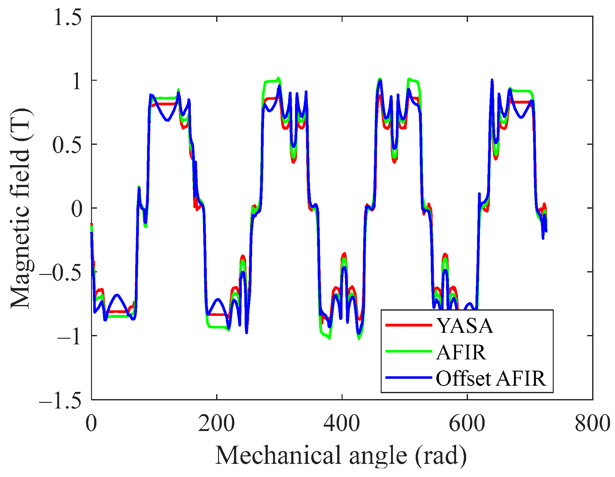
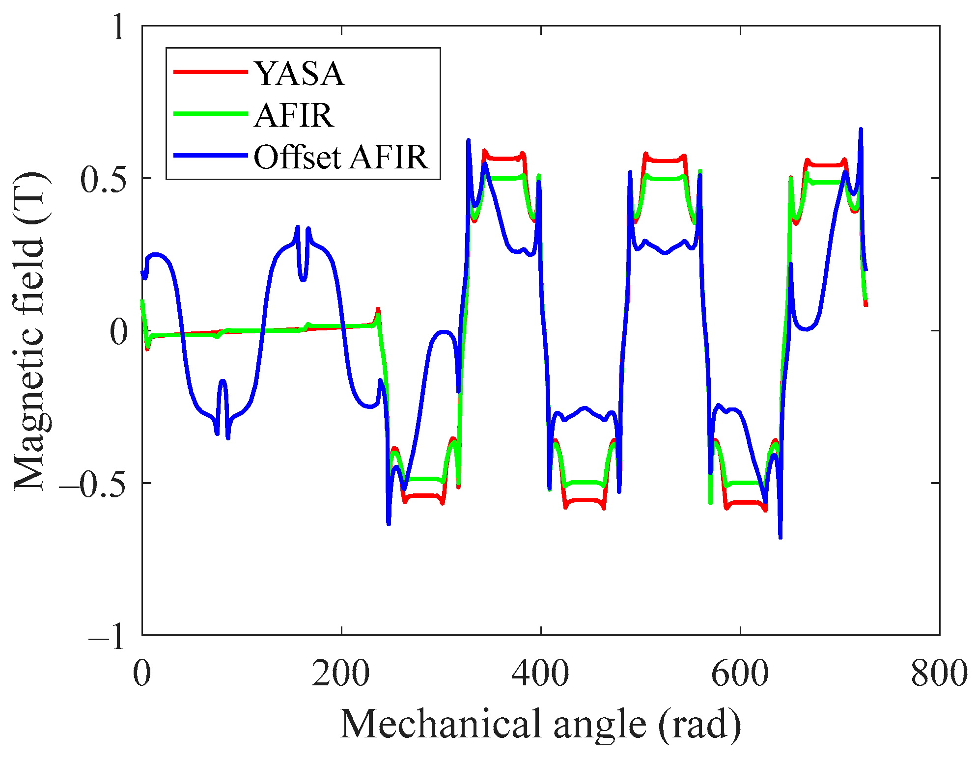
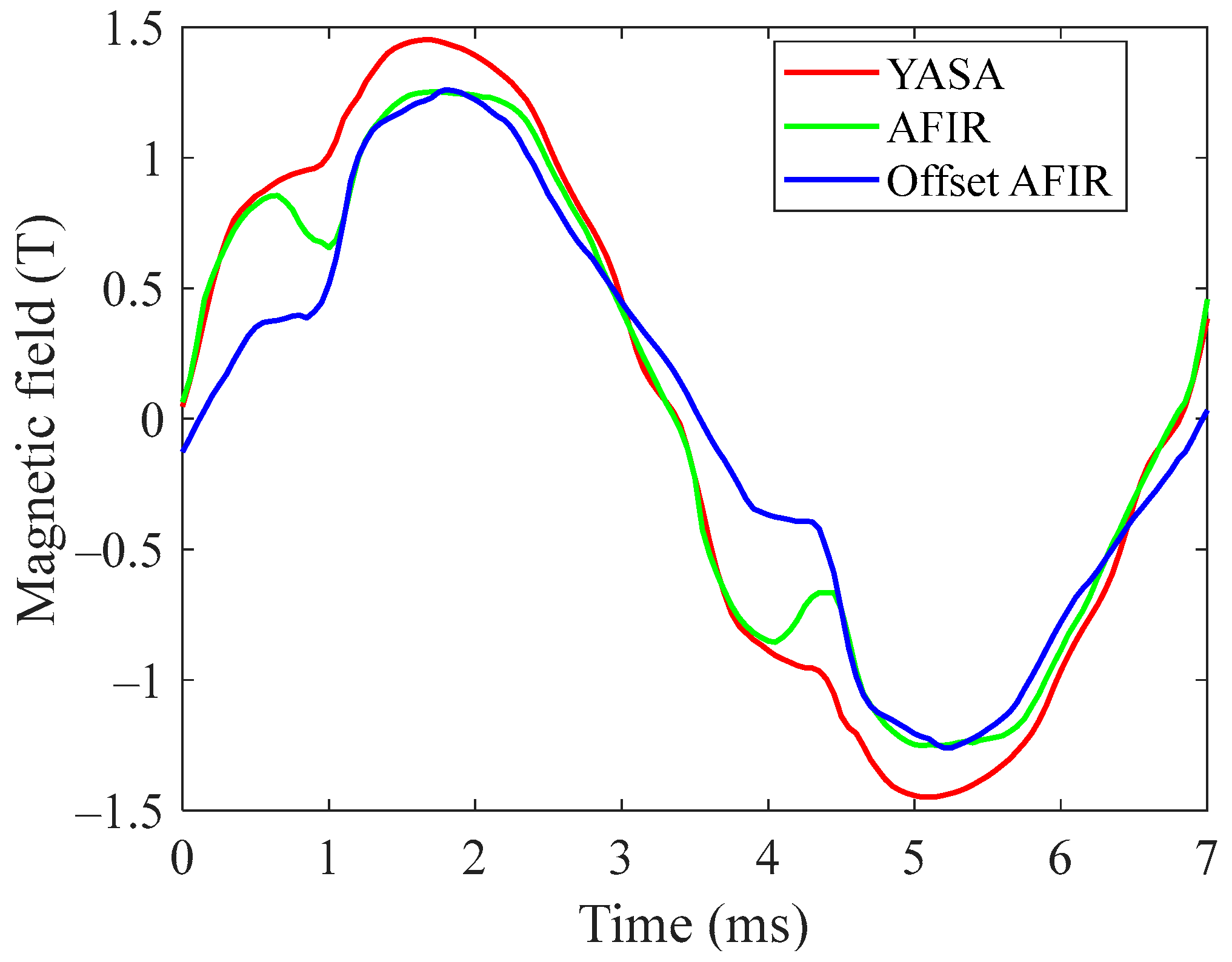
To facilitate a comprehensive comparison among the three topologies, a typical operating condition is selected with a motor speed of 2200 rpm and a current of 200 Arms. In this specific operating scenario, the armature field at time zero seconds in the airgap for all three topologies is depicted in 
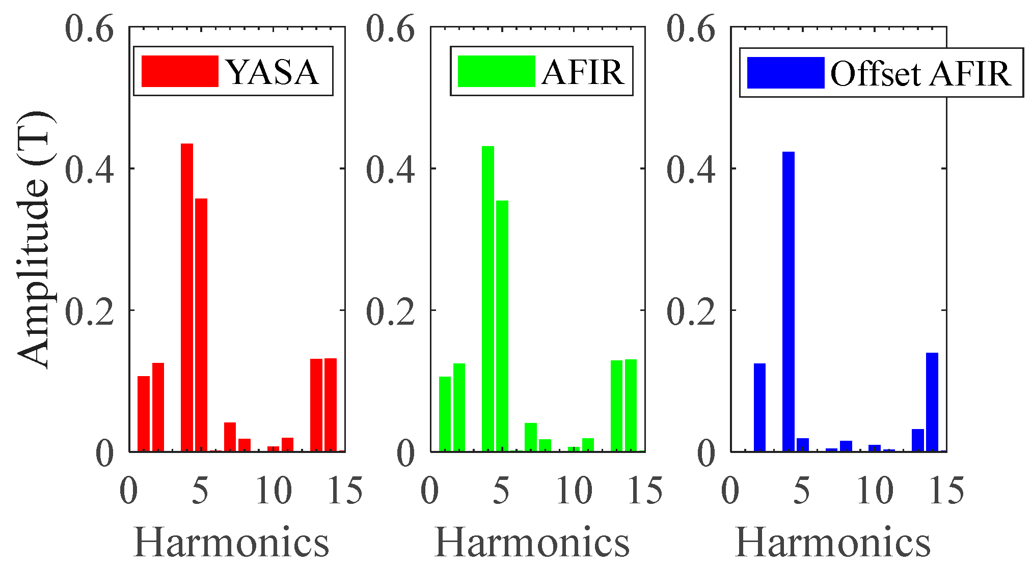
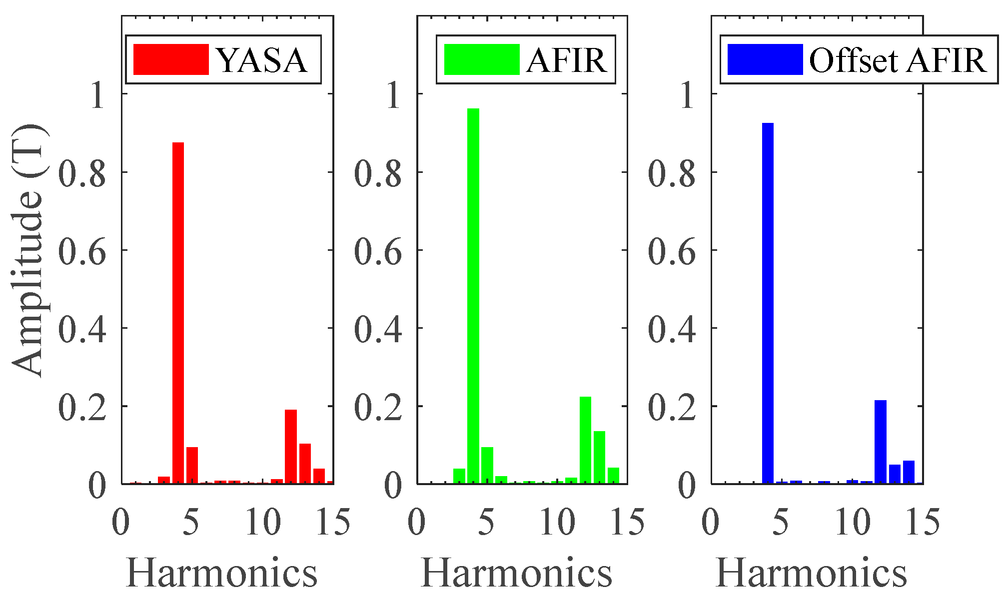
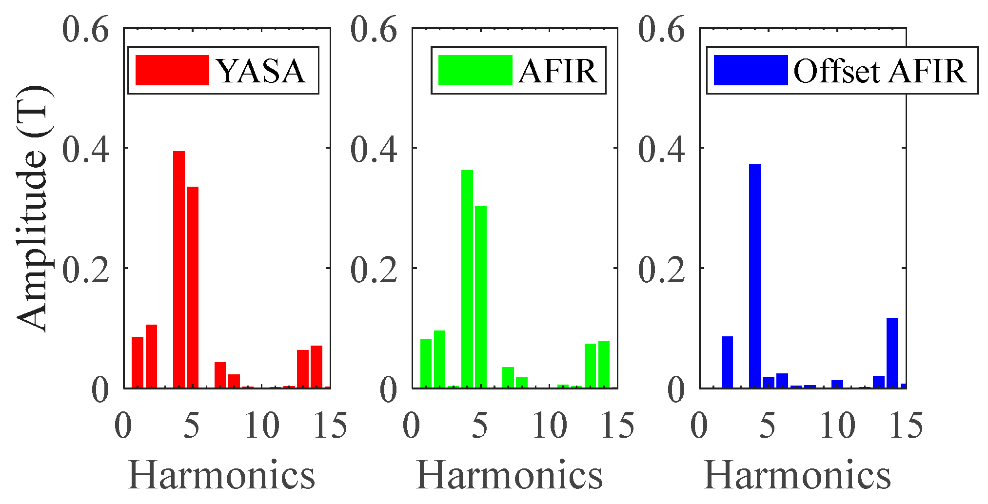
Figure 14. It is notable that the armature field generated by the YASA topology exhibits the highest peak value. An interesting phenomenon can be observed that, due to the phase A winding current at this point being zero, the initial magnetic field of the YASA and AFIR topologies starts from zero, while the offset AFIR does not due to the offset employed. A more detailed insight is provided through the FFT analysis, as illustrated in 
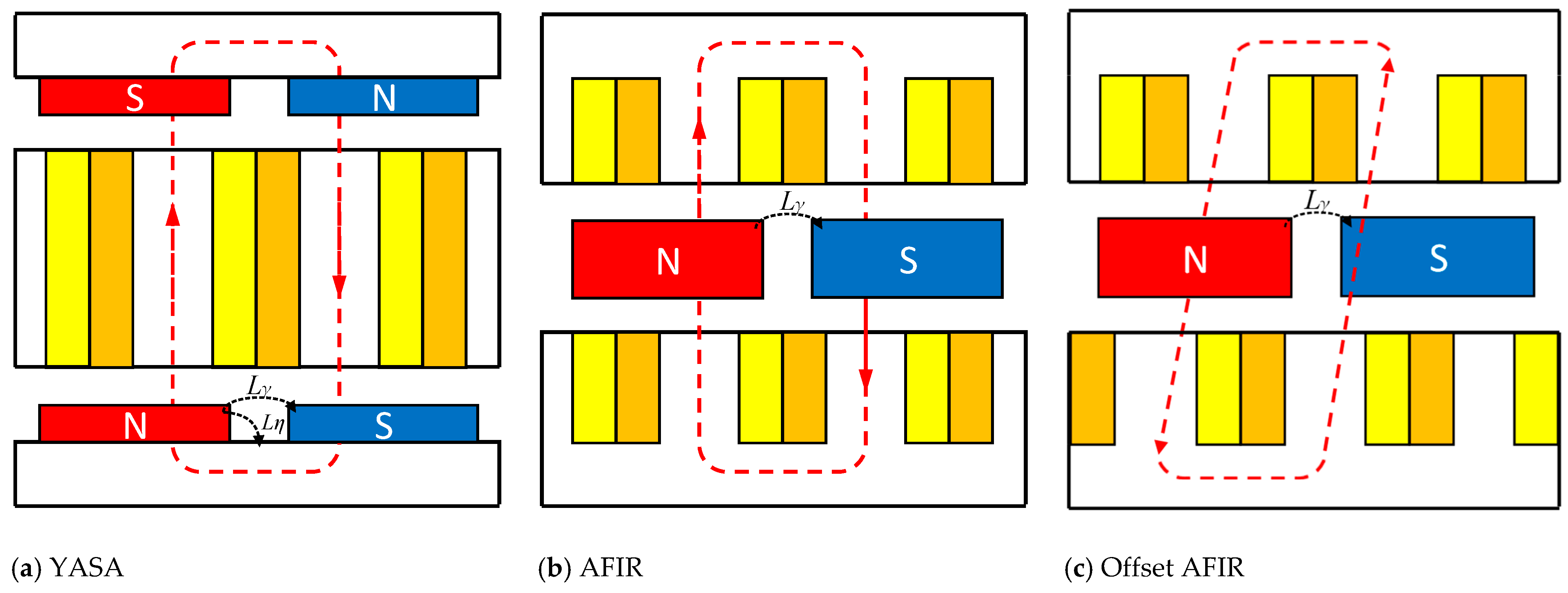
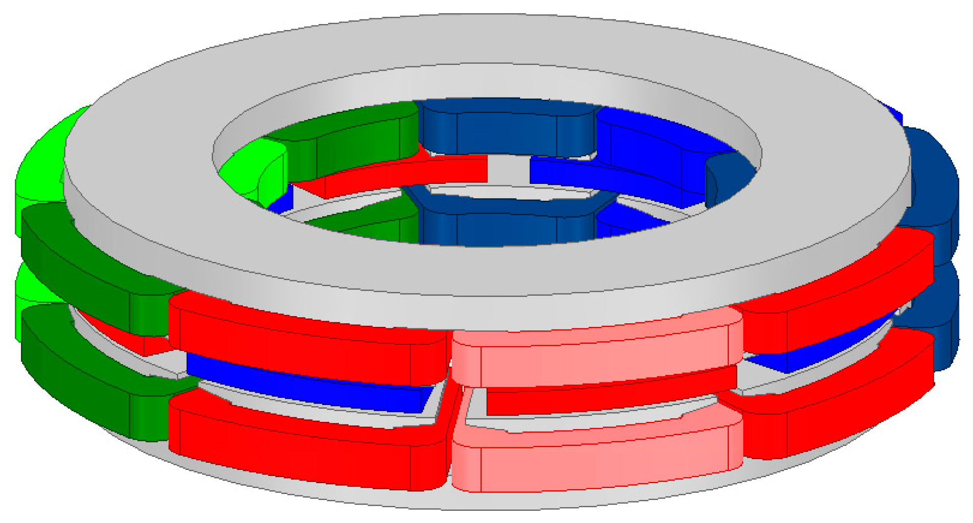
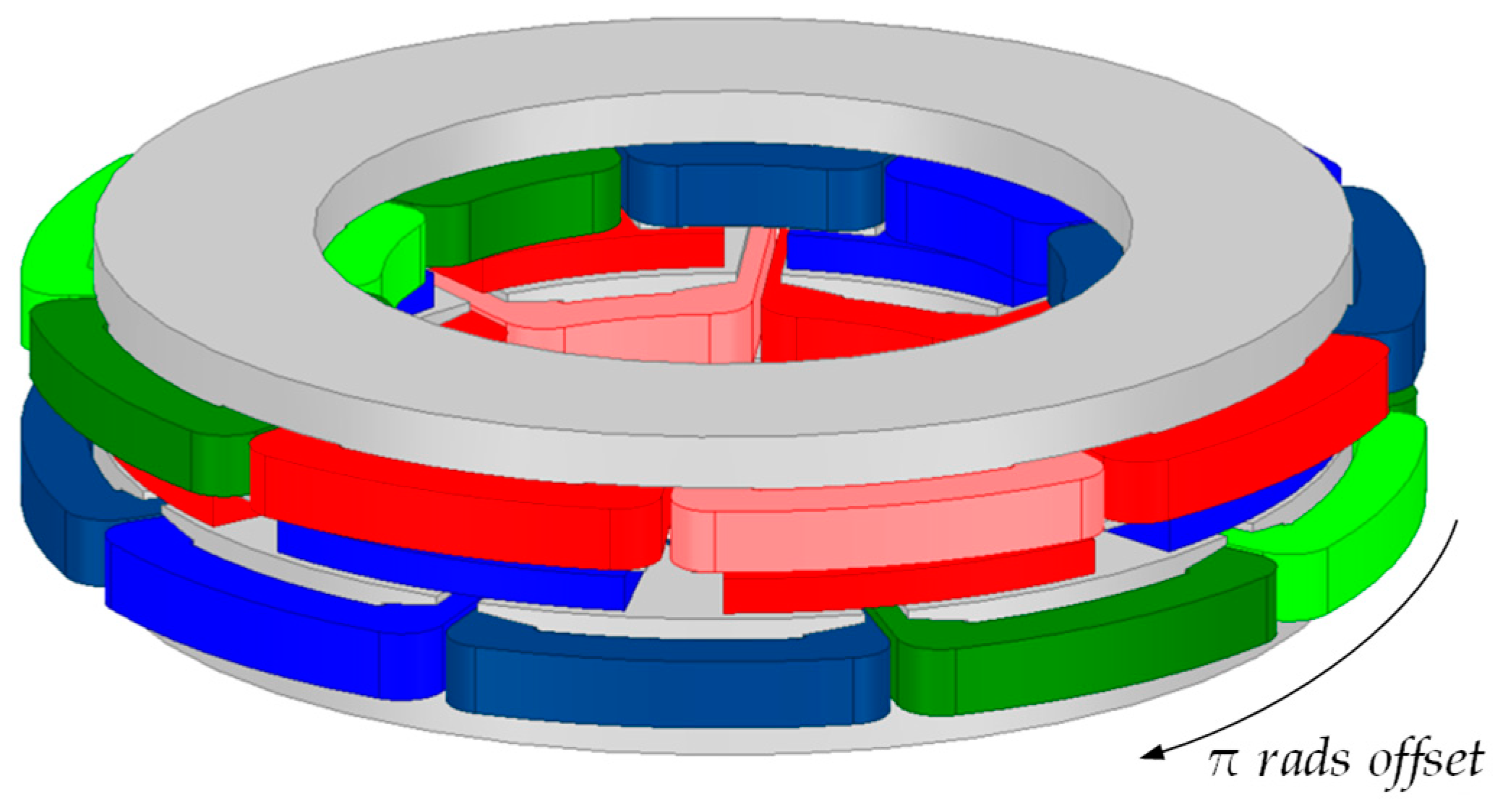
Figure 15. Due to the mechanical π rad offset, as shown in 
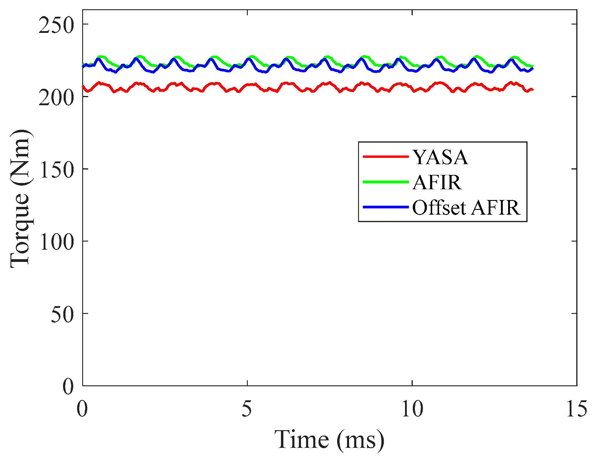
Figure 6, the spatial MMF distribution is more evenly distributed, so, at this instant, there is no zero-flux area along the circumference for the offset AFIR motor, while the YASA and the conventional AFIR motor have zero-flux areas along the circumference. Compared to the fourth harmonic from the YASA topology armature (0.394 T), the AFIR topology armature is reduced by 8.122% (0.362 T) while producing a higher torque. Similarly, the fourth harmonic of the armature field in the offset AFIR topology is reduced by 5.584% (0.372 T) but with a higher torque produced. Furthermore, the offset AFIR topology effectively cancels the fifth harmonic to almost zero. The torque magnitude effectively reflects the varying amplitudes of the fundamental magnetic field, as shown in 
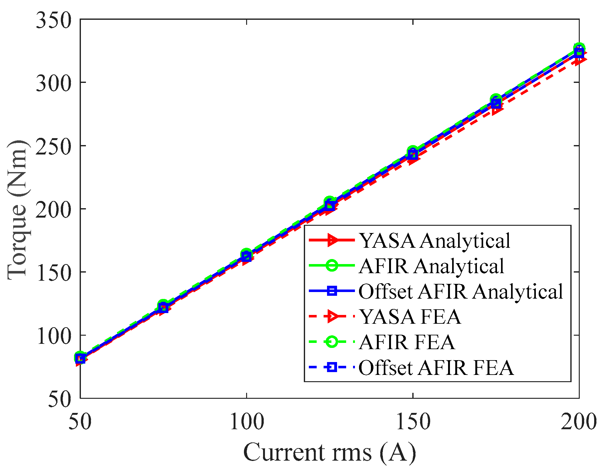
Figure 16, which proves that the torque produced is hardly affected by the offset applied. Both AFIR and offset AFIR topologies produce 220 Nm, which is around 7% higher than the YASA topology. However, with the YASA and AFIR topologies having a similar torque ripple (6.8 Nm and 7.8 Nm, respectively), the torque ripple in the offset AFIR topology is increased to 9.68 Nm due to teeth misalignment.
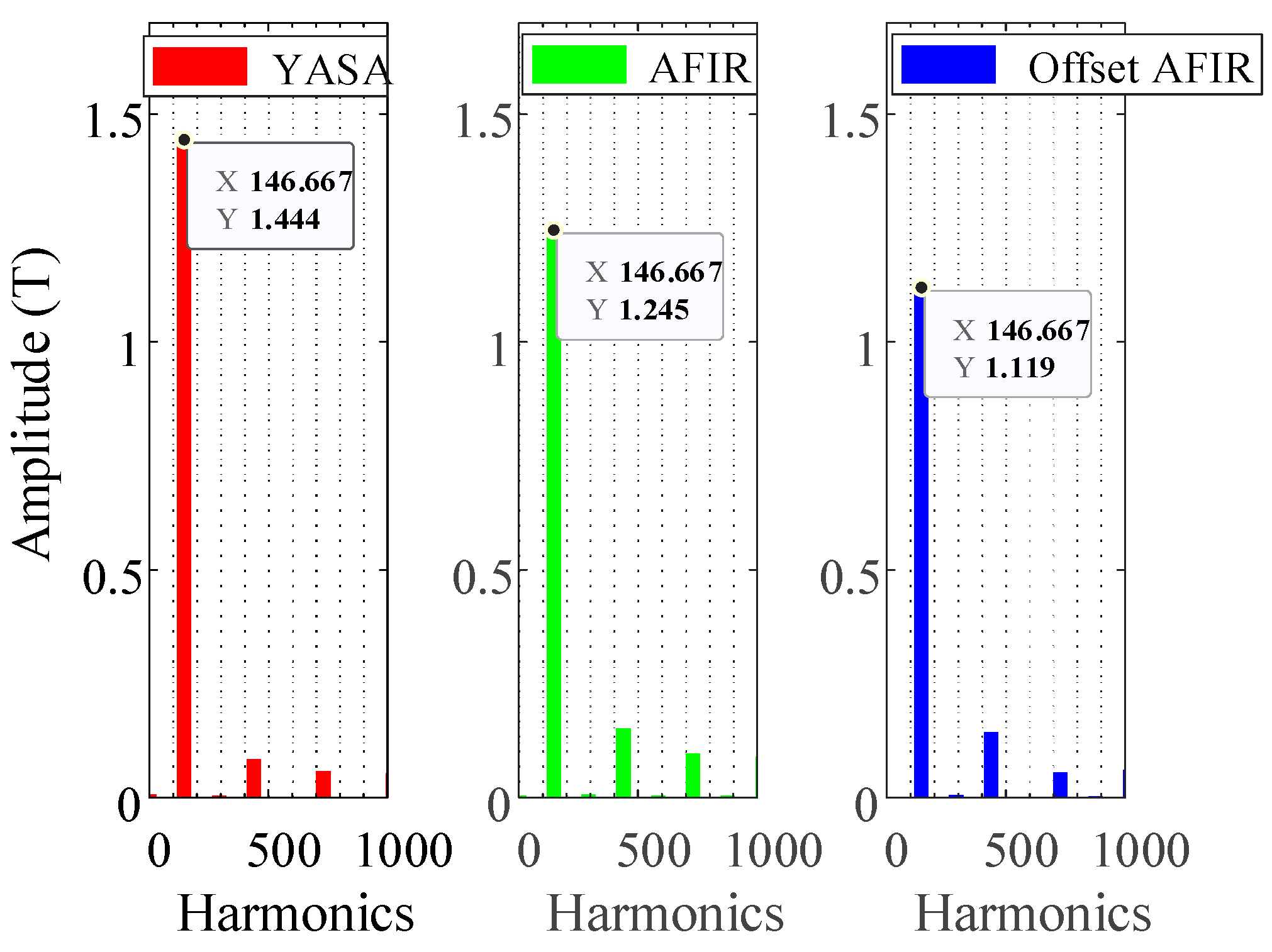
The combination of PM field and armature field results in the flux density in the iron cores depicted in Figure 17. The results are from a fixed point located at the center of a tooth. A detailed illustration of the tooth flux density through the FFT analysis, as presented in Figure 18, highlights that the YASA topology has the highest amplitude for its fundamental harmonic, reaching 1.444 T. Compared with the YASA topology, the AFIR topology achieves a 15.98% reduction, and the offset AFIR topology has a 22.50% reduction under identical operational conditions. These observations suggest that the YASA topology suffers from more severe saturation issues in comparison to the AFIR topology when operating at the same condition. Moreover, the offset AFIR topology exhibits the lowest saturation levels while maintaining torque production.
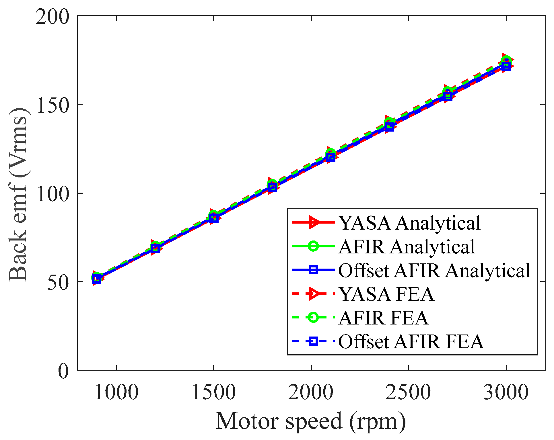
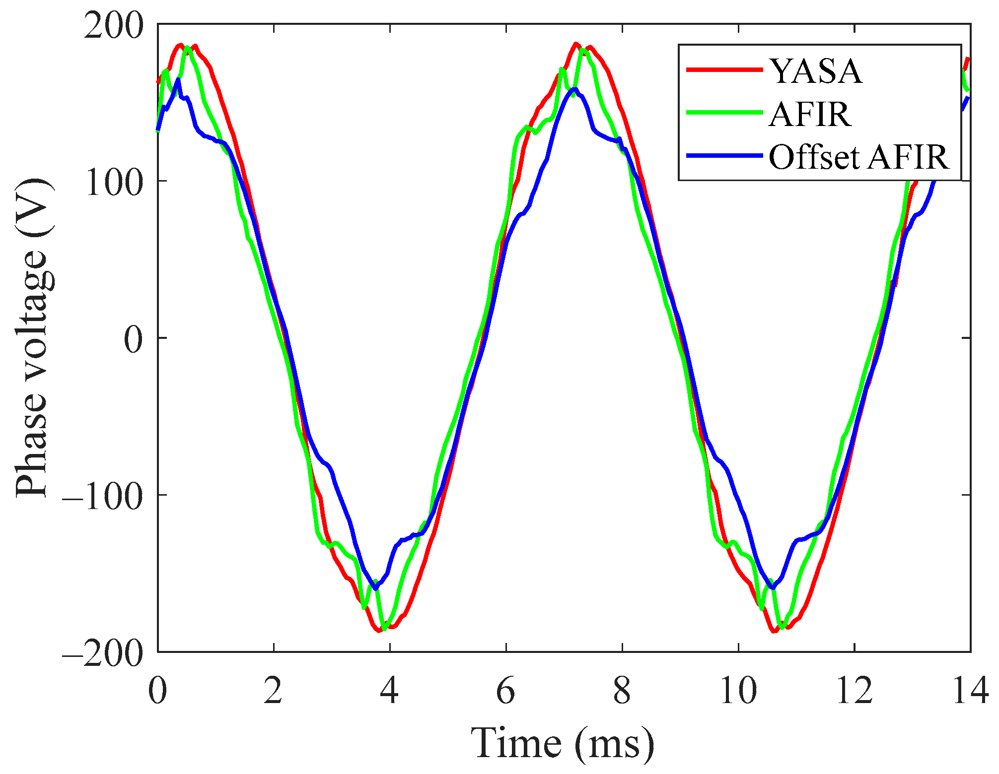
The magnitude of phase voltage presented in Figure 19 aligns with the magnitude of flux density in the teeth, as illustrated in Figure 17. The YASA topology exhibits the highest phase voltage, measuring 129.62 Vrms, due to the highest flux density in the teeth. In contrast, the offset AFIR topology records the lowest phase voltage at 103.74 Vrms, representing a 19.97% reduction. This indicates that the offset AFIR topology can operate under the same load conditions with a higher power factor, which can prove beneficial in terms of converter design and battery specifications, ultimately contributing to cost reduction.
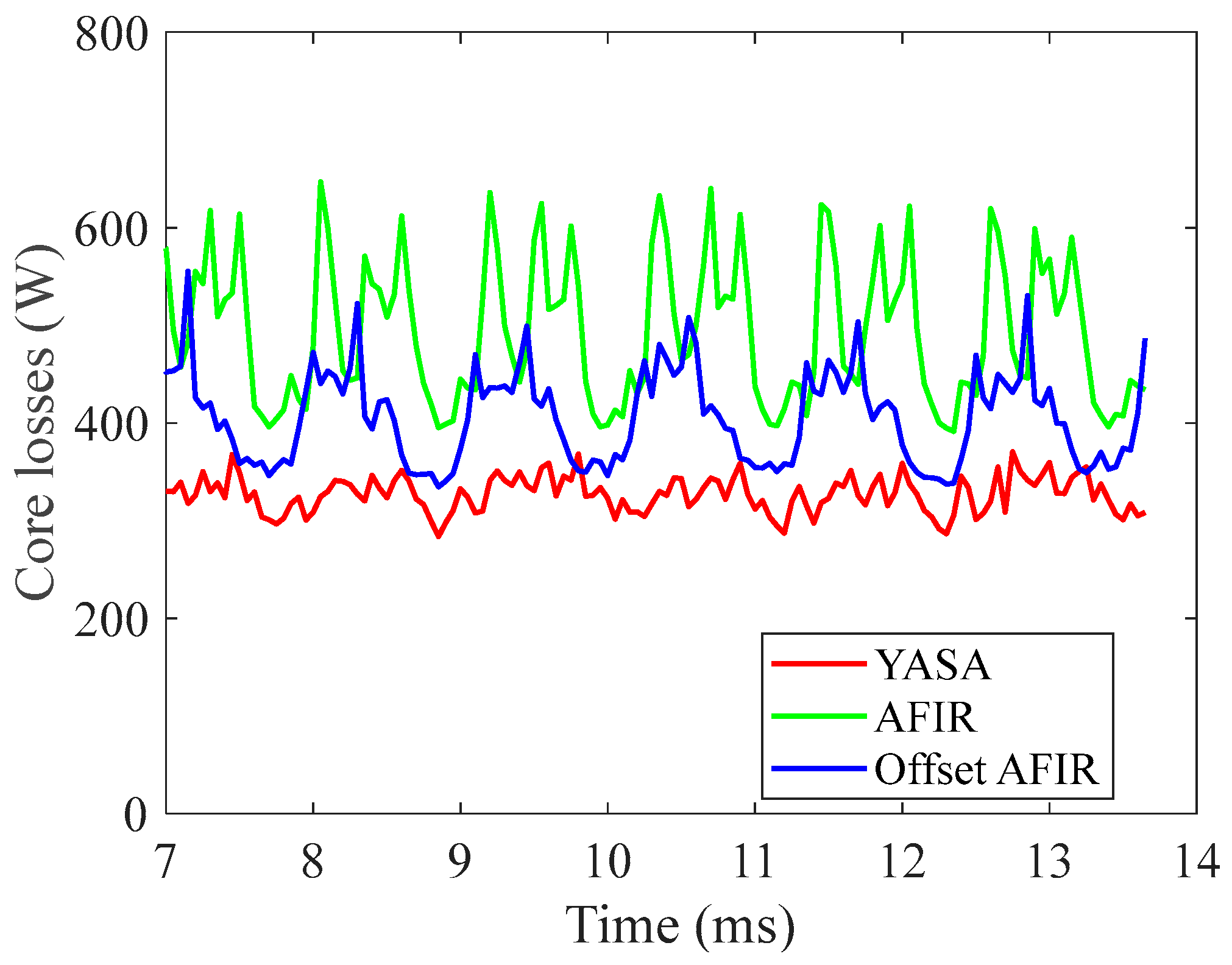
Figure 20 illustrates another crucial aspect of this comparison, including core losses and PM eddy current losses. A detailed explanation of the findings can be derived from the investigation of potential fields contributing to loss production for these three topologies, as presented in Table 5, Table 6 and Table 7. For the YASA topology, the back-iron rotates synchronously with the rotor, eliminating the relative movement between the back-iron and the eight-pole field generated by both PMs and armature windings. Consequently, the eight-pole fields introduce almost no losses in the back-iron. In contrast, the AFIR topology has stationary back-iron on the stator; therefore, the eight-pole fields from PMs and armature windings result in 33.60% higher core losses from 326.95 W to 492.46 W compared to the YASA topology.
The offset AFIR topology cancels the ten-pole field, reducing core losses by 17.78% from 492.46 W to 404.87 W when compared to the AFIR topology. It is worth mentioning that even with harmonic cancellation, the core losses of the offset AFIR topology are still higher than those of the YASA topology, which shows one of the advantages of the YASA topology.
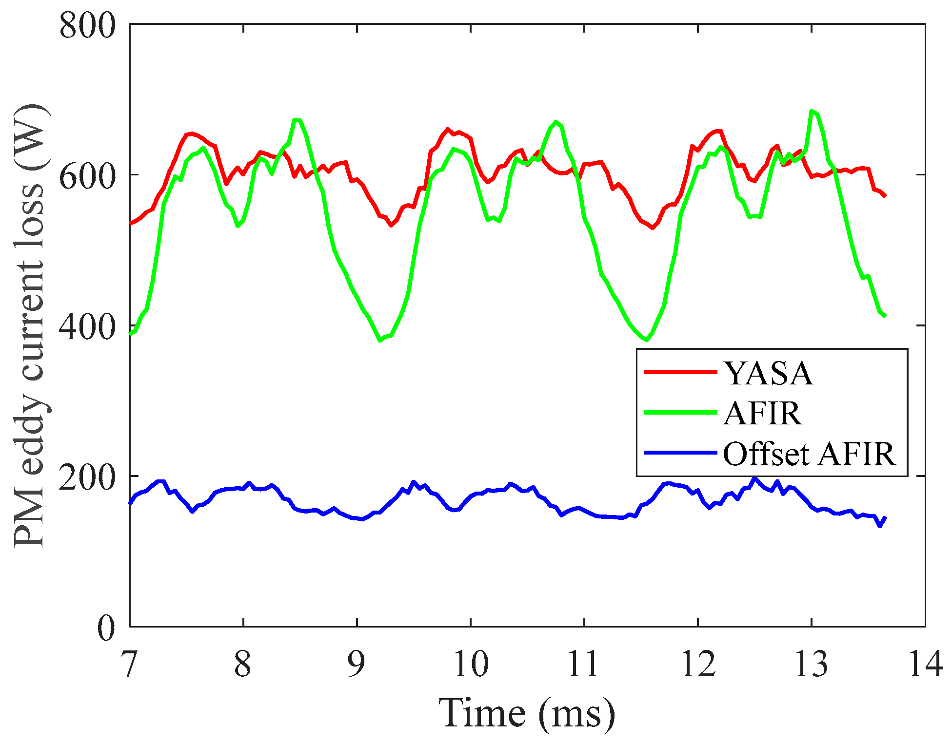
Regarding PM eddy current losses, as shown in Figure 21, the YASA topology and the AFIR topology achieve similar PM losses with values of 603.49 W and 549.14 W, respectively. The offset AFIR topology achieves a significantly lower PM eddy current loss of only 168.02 W, marking a significant reduction of 72.16% compared to YASA and 69.41% in relation to AFIR. This difference stems from the fact that the offset topology eliminates the ten-pole field generated by the armature, reducing loss in the PMs.
These findings imply that the adoption of the offset topology can effectively reduce PM losses, subsequently reducing the demands on the cooling system while maintaining consistent output power levels. This facilitates cooling system designs and holds the potential to reduce the overall footprint, thereby enhancing power density.
Table 8 summarizes the magnetic performance of the YASA, AFIR, and offset AFIR topologies. Under identical physical dimensions and operating conditions of a current load of 200 Arms at 2200 rpm, the YASA topology delivers 206.37 Nm of torque, while the AFIR and the offset AFIR achieve an approximately 8% increase in torque. Furthermore, due to increased flux density in the core, the YASA topology exhibits the highest maximum phase voltage. The AFIR topology achieves an 8.39% reduction in phase voltage and a 12.63% reduction achieved through harmonic cancellation in the offset AFIR topology. The harmonic cancellation leads to the power factor being improved by 13.69% in the offset AFIR topology compared to the YASA and AFIR topologies. However, due to the unique feature where both back-iron regions rotate with the magnets, the YASA topology achieves the lowest core losses among the three topologies. With the application of the offset technique, the offset AFIR topology shows a reduction in core losses.
Examining PM losses, both the YASA and AFIR topologies suffer substantial PM eddy current losses, while the offset AFIR topology achieves a remarkable 70% reduction in PM losses. This achievement is noteworthy, considering the challenges of dissipating heat from rotating components.
Despite having lower core losses, the YASA topology’s reduced torque production results in an efficiency of 95.37%. The AFIR topology, with slightly higher output power but significant core losses, achieves a similar efficiency of 95.51%. Notably, the offset AFIR topology achieves the highest efficiency of 96.30% due to harmonic cancellation while maintaining output power.
In conclusion, the selection of the optimal topology depends on the specific requirements for applications. For instance, when high torque density is preferred, the AFIR topology is the preferred choice. Alternatively, if cost-effective iron core materials and reduced core losses are the objectives, the YASA topology provides advantages. When higher efficiency is the target, the offset AFIR topology emerges as the preferred option. Moreover, the offset AFIR topology brings additional advantages, such as lower phase voltage and reduced overall losses, potentially leading to cost savings in DC bus and cooling system designs. The offset AFIR configuration may attract considerable attention due to the additional benefits it brings.

4. Conclusions

This paper presents a comprehensive examination of the magnetic characteristics and performance of three types of AFPM motors: the YASA, AFIR, and offset AFIR topologies.
The study started with an analytical analysis of the ideal scenario, which revealed that three topologies can produce nearly identical torque densities. Using real materials in 3D simulation and under consistent operating conditions, torque and back-emf results were compared to experimental data from the commercial YASA P400, and the similarity between the simulation and experimental results verifies the effectiveness of the 3D models.
From the results, the offset AFIR topology achieves the highest efficiency, lowest induced voltage, and significantly low PM losses, which may benefit the cooling system design and converter design. The AFIR topology achieves the highest torque, which is 8% more compared with the YASA topology, while the YASA topology features the lowest core losses.

Author Contributions

Conceptualization, X.P. and J.F.E.; methodology, H.W., X.P. and J.F.E.; software, H.W.; validation, H.W., X.P. and X.Z.; formal analysis, H.W., X.P. and J.F.E.; investigation, H.W., X.P. and J.F.E.; data curation, H.W. and X.P.; writing—original draft preparation, H.W. and X.P.; writing—review and editing, J.F.E. and X.Z.; supervision, X.P. and X.Z. All authors have read and agreed to the published version of the manuscript.

Funding

This research received no external funding.

Data Availability Statement

The raw data supporting the conclusions of this article will be made available by the authors on request.

Conflicts of Interest

The authors declare no conflict of interest.

References

  1. Gieras, J.F.; Wang, R.-J.; Kamper, M.J. Axial Flux Permanent Magnet Brushless Machines; Springer Science & Business Media: Berlin, Germany, 2008; ISBN 978-1-4020-8227-6. [Google Scholar]
  2. Aydin, M.; Huang, S.; Lipo, T.A. Axial Flux Permanent Magnet Disc Machines: A Review. Conf. Rec. SPEEDAM 2004, 8, 61–71. [Google Scholar]
  3. Nishanth, F.; Van Verdeghem, J.; Severson, E.L. A Review of Axial Flux Permanent Magnet Machine Technology. IEEE Trans. Ind. Appl. 2023, 59, 3920–3933. [Google Scholar] [CrossRef]
  4. Campbell, P. Principles of a Permanent-Magnet Axial-Field d.c. Machine. Proc. Inst. Electr. Eng. 1974, 121, 1489–1494. [Google Scholar] [CrossRef]
  5. Amin, S.; Khan, S.; Hussain Bukhari, S.S. A Comprehensive Review on Axial Flux Machines and Its Applications. In Proceedings of the 2019 2nd International Conference on Computing, Mathematics and Engineering Technologies (iCoMET), Sukkur, Pakistan, 30–31 January 2019; pp. 1–7. [Google Scholar]
  6. Evans, P.D.; Brown, D.; Eastham, J.F. A Study of Permanent Magnet Disc Motor Design. In Proceedings of the BICEM Proceedings, Beijing, China, 10–14 August 1987; pp. 729–732. [Google Scholar]
  7. Spooner, E.; Chalmers, B.J. ‘TORUS’: A Slotless, Toroidal-Stator, Permanent-Magnet Generator. IEE Proc. B (Electr. Power Appl.) 1992, 139, 497–506. [Google Scholar] [CrossRef]
  8. Woolmer, T.J.; McCulloch, M.D. Analysis of the Yokeless and Segmented Armature Machine. In Proceedings of the 2007 IEEE International Electric Machines & Drives Conference, Antalya, Turkey, 3–5 May 2007; Volume 1, pp. 704–708. [Google Scholar]
  9. Woolmer, T.J.; McCulloch, M.D. Axial Flux Permanent Magnet Machines: A New Topology for High Performance Applications. In Proceedings of the IET—The Institution of Engineering and Technolgy Hybrid Vehicle Conference 2006, Coventry, UK, 12–13 December 2006; pp. 27–42. [Google Scholar]
  10. Kahourzade, S.; Mahmoudi, A.; Ping, H.W.; Uddin, M.N. A Comprehensive Review of Axial-Flux Permanent-Magnet Machines. Can. J. Electr. Comput. Eng. 2014, 37, 19–33. [Google Scholar] [CrossRef]
  11. Parviainen, A.; Niemela, M.; Pyrhonen, J. Modeling of Axial Flux Permanent-Magnet Machines. IEEE Trans. Ind. Appl. 2004, 40, 1333–1340. [Google Scholar] [CrossRef]
  12. Wang, H.; Pei, X.; Yin, B.; Eastham, J.F.; Vagg, C.; Zeng, X. A Novel Double-Sided Offset Stator Axial-Flux Permanent Magnet Motor for Electric Vehicles. World Electr. Veh. J. 2022, 13, 52. [Google Scholar] [CrossRef]
  13. Zhu, Z.Q.; Howe, D. Instantaneous Magnetic Field Distribution in Brushless Permanent Magnet DC Motors. III. Effect of Stator Slotting. IEEE Trans. Magn. 1993, 29, 143–151. [Google Scholar] [CrossRef]
  14. Qu, R.; Lipo, T.A. Analysis and Modeling of Air-Gap and Zigzag Leakage Fluxes in a Surface-Mounted Permanent-Magnet Machine. IEEE Trans. Ind. Appl. 2004, 40, 121–127. [Google Scholar] [CrossRef]
  15. Mahmoudi, A.; Ping, H.W.; Rahim, N.A. A Comparison between the TORUS and AFIR Axial-Flux Permanent-Magnet Machine Using Finite Element Analysis. In Proceedings of the 2011 IEEE International Electric Machines & Drives Conference (IEMDC), Niagara Falls, ON, Canada, 15–18 May 2011; pp. 242–247. [Google Scholar]
  16. Huang, S.; Luo, J.; Leonardi, F.; Lipo, T.A. A General Approach to Sizing and Power Density Equations for Comparison of Electrical Machines. IEEE Trans. Ind. Appl. 1998, 34, 92–97. [Google Scholar] [CrossRef]
  17. Huang, S.; Luo, J.; Leonardi, F.; Lipo, T.A. A Comparison of Power Density for Axial Flux Machines Based on General Purpose Sizing Equations. IEEE Trans. Energy Convers. 1999, 14, 185–192. [Google Scholar] [CrossRef]
  18. Martin, R. Axial Flux Permanent Magnet Machines for Direct Drive Applications. Ph.D. Thesis, Durham University, Durham, UK, 2007. [Google Scholar]
  19. Jensen, C.C.; Profumo, F.; Lipo, T.A. A Low-Loss Permanent-Magnet Brushless DC Motor Utilizing Tape Wound Amorphous Iron. IEEE Trans. Ind. Appl. 1992, 28, 646–651. [Google Scholar] [CrossRef]
  20. Allca-Pekarovic, A.; Kollmeyer, P.J.; Forsyth, A.; Emadi, A. Experimental Characterization and Modeling of a YASA P400 Axial Flux PM Traction Machine for Electric Vehicles. In Proceedings of the 2022 IEEE Transportation Electrification Conference & Expo (ITEC), Anaheim, CA, USA, 15–17 June 2022; pp. 433–438. [Google Scholar]
  21. Gerlando, A.D.; Foglia, G.; Ricca, C. Analytical Design of a High Torque Density In-Wheel YASA AFPM Motor. In Proceedings of the 2020 International Conference on Electrical Machines (ICEM), Gothenburg, Sweden, 23–26 August 2020; Volume 1, pp. 402–408. [Google Scholar]
  22. Eastham, J.F.; Cox, T.; Proverbs, J. Application of Planar Modular Windings to Linear Induction Motors by Harmonic Cancellation. IET Electr. Power Appl. 2010, 4, 140–148. [Google Scholar] [CrossRef]
Figure 1. Comparison of YASA, AFIR, and offset AFIR topologies.
Energies 17 00401 g001
Figure 2. Volume comparison for different torque demands for three topologies.
Energies 17 00401 g002
Figure 3. Comparison of torque density against outer radius for three topologies.
Energies 17 00401 g003
Figure 4. A 3D model for the YASA topology.
Energies 17 00401 g004
Figure 5. A 3D model for the AFIR topology.
Energies 17 00401 g005
Figure 6. A 3D model for the offset AFIR topology.
Energies 17 00401 g006
Figure 7. FFT analysis for the armature field in the airgap.
Energies 17 00401 g007
Figure 8. Analytical and simulation results comparison of back-emf for YASA, AFIR, and offset AFIR topologies.
Energies 17 00401 g008
Figure 9. Torque analytical results and simulation results comparison for YASA, AFIR, and offset AFIR topologies.
Energies 17 00401 g009
Figure 10. Torque 3D simulation results for three topologies with JFE-50-JN270 and YASA P400 experimental results.
Energies 17 00401 g010
Figure 11. PM field in the airgap.
Energies 17 00401 g011
Figure 12. FFT analysis for the PM field in the airgap.
Energies 17 00401 g012
Figure 13. Comparison between experiment and simulation results of back-emf for YASA, AFIR, and offset AFIR topologies.
Energies 17 00401 g013
Figure 14. Armature field in the airgap at time zero seconds with 200 Arms.
Energies 17 00401 g014
Figure 15. FFT analysis for the armature field in the airgap at time zero seconds with 200 Arms.
Energies 17 00401 g015
Figure 16. Torque comparison for three topologies at 2200 rpm and 200 Arms.
Energies 17 00401 g016
Figure 17. Flux density in teeth at 2200 rpm and 200 Arms.
Energies 17 00401 g017
Figure 18. FFT analysis of the flux density in teeth at 2200 rpm and 200 Arms.
Energies 17 00401 g018
Figure 19. Phase voltage comparison at 2200 rpm and 200 Arms.
Energies 17 00401 g019
Figure 20. Core loss comparison at 2200 rpm and 200 Arms.
Energies 17 00401 g020
Figure 21. PM eddy current loss comparison at 2200 rpm and 200 Arms.
Energies 17 00401 g021
Table 1. Specifications and dimensions used for 3D models of three topologies.
ParameterValue
Pole–pair number 4
Magnet span0.8
Magnet thickness 8 mm (total)
Outer diameter 280 mm
Ratio of inner to outer diameter0.65
Slot number9
Airgap length1.5 mm
Active length79.2 mm
Number of turns per phase20
Table 2. Amplitude of fundamental harmonic of the PM field in the airgap for three topologies.
TopologyAnalytical (T)3D FEA (T)Difference (%)
YASA1.1541.1630.736
AFIR1.1661.1630.206
Offset AFIR1.1661.1610.386
Table 3. Winding factor for YASA and AFIR topologies.
Pole–PairPPSNPS
10.06060
200.1398
300
40.94520
500.9452
600
70.13980
800.0606
900
100.06060
Table 4. Winding factor for offset AFIR topology.
Pole–PairPPSNPS
100
200.1398
300
40.94520
500
600
700
800.0606
900
100.06060
Table 5. Regions that contribute to losses in YASA topology.
FieldPMsBack-IronStator Teeth
8-pole PMs field NoNoYes
8-pole armature field NoNoYes
10-pole armature field YesYesYes
Table 6. Regions that contribute to losses in AFIR topology.
FieldPMsBack-IronStator Teeth
8-pole PMs field NoYYes
8-pole Armature field NoYYes
10-pole Armature field YYYes
Table 7. Regions that contribute to losses in offset AFIR topology.
FieldPMsBack-IronStator Teeth
8-pole PMs fieldNoYesYes
8-pole armature field NoYesYes
10-pole armature field NoNoNo
Table 8. Comparison of magnetic performance of three topologies at 2200 rpm and 200 Arms.
ParameterYASAAFIROffset
AFIR
Torque (Nm)206.37223.29220.74
Speed (rpm)220022002200
Phase voltage (V)129.62118.74103.74
Power factor0.720.740.83
Core losses (W)326.95492.46404.86
PM loss (W)603.49549.14168.02
Copper loss (W)1378.511378.511378.51
Total loss (W)2308.952420.111951.33
Efficiency (%)95.3795.5196.30
Disclaimer/Publisher’s Note: The statements, opinions and data contained in all publications are solely those of the individual author(s) and contributor(s) and not of MDPI and/or the editor(s). MDPI and/or the editor(s) disclaim responsibility for any injury to people or property resulting from any ideas, methods, instructions or products referred to in the content.

