Article

Primary Frequency Regulation Strategy Based on Rotor Kinetic Energy of Double-Fed Induction Generator and Supercapacitor

1
Central South Electric Power Test and Research Institute, China Datang Corporation Science and Technology Research Institute, Zhengzhou 450007, China
2
Hebei Key Laboratory of Distributed Energy Storage and Microgrid, North China Electric Power University, Baoding 071000, China
*
Author to whom correspondence should be addressed.
Energies 2024, 17(2), 331; https://doi.org/10.3390/en17020331
Submission received: 16 November 2023 / Revised: 23 December 2023 / Accepted: 5 January 2024 / Published: 9 January 2024
(This article belongs to the Special Issue Advancement in Wind Turbine Technology)

Abstract

:
To address the challenge of wind turbines meeting primary frequency regulation requirements, incorporating energy storage devices to handle most of the frequency regulation tasks would result in increased operational costs. When a wind turbine rotor accelerates, it deviates from the maximum power tracking point (MPPT), leading to reduced output while retaining significant rotational kinetic energy. Based on this characteristic, a primary frequency regulation strategy is proposed that coordinates the rotor kinetic energy of a double-fed induction generator (DFIG) with supercapacitors (SCs). Supercapacitors provide power support during low-frequency conditions, while accelerating the wind turbine rotor reduces output during high-frequency conditions. Additionally, continuous attention is given to subsequent frequency changes. In case of short-term, low-frequency conditions, stored kinetic energy is released for power support, establishing a mechanism for wind turbine kinetic energy recovery and release. This mechanism reduces charging and discharging requirements for supercapacitors, extends their service life, and considers both wind turbine frequency regulation requirements and economy. Finally, using MATLAB 2020/Simulink platform allows for the verification of the effectiveness and rationality of this proposed method.

1. Introduction

With the introduction of a “double carbon” strategy, the wind power industry is continuously advancing technologically, leading to an increase in installed capacity. As of April 2023, China’s wind power installed capacity reached 380 million kilowatts, accounting for 14.3% of the national power generation installed capacity. However, the inherent stochasticity and volatility associated with wind power generation have exacerbated the power imbalance between supply and demand, posing a serious threat to grid frequency stability [1]. Ensuring grid frequency safety and stability becomes particularly crucial as wind power penetration continues to rise.
To ensure economic benefits, wind turbines are typically operated at the MPPT to optimize their performance. However, when participating in primary frequency regulation by utilizing rotor kinetic energy, wind turbines provide additional power support under low-frequency conditions (where the frequency drop exceeds the lower limit of the dead zone). This requires the release of rotational kinetic energy, resulting in a decrease in rotor speed and deviation from optimal power output, thereby limiting the wind turbine’s ability to provide additional output. Moreover, if the rotor speed drops to its protection limit and needs quick recovery, it would consume a significant amount of power and lead to a substantial shortage that hampers system frequency recovery. Consequently, wind turbines cannot meet the frequency support requirements for primary frequency regulation during low-frequency operating conditions for 20–30 s.
Energy storage, serving as a superior power source for frequency regulation, offers advantages such as precise tracking, rapid response, and bidirectional regulation. It has gained extensive application in wind power generation systems, attracting significant attention from domestic and international scholars who have conducted research on energy storage control strategies and capacity configuration [2].
The authors in reference [3,4] devoted themselves to meticulously modeling a Li-ion battery energy storage system (BESS), which was found to significantly improve the grid connection stability of DFIG wind turbines. Their work provides essential models and references for further research. Reference [5] emphasizes from an economic standpoint that implementing wind power assembly energy storage as primary frequency regulation offers a more cost-effective solution. This strategy maximizes utilization of the wind turbine rotor’s kinetic energy while minimizing the necessary energy storage capacity. The authors of references [6,7,8] investigate various energy storage devices such as SCs, flywheel energy storage systems, lithium batteries, and hydrogen fuel cells to examine their effects on primary frequency regulation. From the perspective of coefficient optimization, various methods such as linear segmentation, S-function, and fuzzy control were employed in [9] to rectify the charging and discharging coefficients. This amendment effectively mitigates the issues of over-charging and over-discharging in energy storage systems. References [10,11] concentrate on optimizing the allocation ratio of frequency regulation resources by introducing dynamic optimization coefficients through fuzzy control. Consequently, wind turbines’ adaptability for frequency regulation is significantly enhanced. Moreover, energy storage devices like SCs can further augment the power support capacity of wind turbines during low-frequency conditions.
In conditions of high-frequency conditions (where the frequency rise exceeds the upper limit of the dead zone), wind turbines can easily adjust their power output. While the rotor needs to absorb power during acceleration, wind turbines may deviate from the optimal power tracking point. However, there are no inherent limitations that restrict wind turbines from reducing their output. Therefore, wind turbines are more suitable for participating in frequency regulation under high-frequency operating conditions. Additionally, wind turbines retain a significant amount of rotational kinetic energy during the acceleration process which, if effectively harnessed, can further alleviate energy storage requirements in low-frequency conditions and minimize configuration demands for energy storage.
Therefore, based on the power-speed characteristics of wind turbines, this paper proposes a primary frequency regulation strategy that coordinates rotor kinetic energy and SC. Under low-frequency conditions, SCs support power generation, while under high-frequency conditions, the wind turbine rotor accelerates and reduces output. Continuous attention is given to subsequent frequency changes. In the case of short-term low-frequency conditions, stored kinetic energy is released to provide support, forming a mechanism for wind turbine kinetic energy recovery and release. This mechanism reduces the charging and discharging requirements of the SC system, extends its service life, and considers the requirements for wind turbine frequency regulation and economy. Additionally, for switching between rotor kinetic energy and SC strategies, this paper comprehensively considers the state of charge (SOC) of SC energy storage and introduces a logistic function to real-time correct allocation coefficients of DFIG and SC resources in order to achieve smooth switching between different energy storage resources. Finally, simulations were conducted using the MATLAB/Simulink wind storage joint frequency regulation model in short-term/long-term frequency fluctuation scenarios to verify the effectiveness and rationality of the proposed frequency regulation strategy.
The subsequent sections of this paper are structured as follows: Section 2 provides a concise analysis of the frequency regulation characteristics exhibited by wind turbines. In Section 3, an elaborate presentation is given on the collaborative primary frequency regulation control strategy. Section 4 validates the feasibility of the proposed control strategy and compares it with other conventional approaches. Finally, concluding remarks are presented in Section 5.

2. Frequency Regulation Characteristics of DFIG

According to “Technical Specification for Power Grid and Source Coordination (DL/T 1870–2018)” [12], the primary frequency regulation dead zone should be controlled within ±0.05 Hz. To comply with this requirement, the dead zone of both DFIG and thermal power units is uniformly set at ±0.033 Hz. When the frequency deviation exceeds +0.033 Hz, it indicates a high-frequency operating condition, triggering the initiation of frequency rise regulation. Conversely, when the deviation drops below −0.033 Hz, it signifies a low-frequency operating condition and initiates frequency reduction regulation.
Based on reference [13], it has been observed that throughout the year, there is a probability of less than 10% for forecasted wind speed to exceed the turbine’s rated wind speed by over 80%. Considering this information along with the MPPT curve analysis, it can be inferred that at lower wind speeds, the rotor speed at DFIG’s MPPT point is comparatively lower while allowing for a wide range of adjustment on its right side. This characteristic can be effectively utilized to enhance efficiency in wind power generation systems.
The transformation process of DFIG participating in frequency rise regulation is illustrated in Figure 1, where the horizontal axis represents the rotor speed of the wind turbine ωr and the vertical axis represents the output electromagnetic power. Under normal frequency conditions, the wind turbine operates stably at point A with MPPT control, corresponding to the optimal speed ωopt. In case of a sudden increase in system frequency, the output electromagnetic power instantly decreases to point B. With additional power from traditional virtual inertia control, the wind turbine absorbs kinetic energy of the rotor, causing an increase in rotor speed and gradually transitioning to point C, reaching its highest rotor speed ω1 during this frequency regulation. Once it has reached point C, when the wind turbine runs back into dead zone frequencies, it switches back to MPPT control and returns along the MPPT curve to operating point A.
It is worth noting that during this process, as the operating range of ωr lies between 0.7 and 1.2 pu, the magnitude of rotor kinetic energy becomes significant. On one hand, a sudden release of rotor speed can potentially destabilize the system frequency. On the other hand, in practical scenarios, continuous fluctuations in system frequency are observed. Based on statistical data from reference [5], within a day, there are a total of 1670 instances where bus frequency crosses the dead zone for frequency regulation in a specific area’s power grid; among these occurrences, 720 times exceed the upper limit while 950 times exceed the lower limit of this dead zone. Therefore, a strategy can be proposed to optimize the utilization of the available space on the right side of the MPPT point by enabling temporary storage of rotor kinetic energy stored from the frequency rise, as a contingency measure for subsequent frequency fluctuations.

3. Frequency Regulation Strategy Based on Rotor Kinetic Energy of DFIG and SC

This paper investigates the potential for long-term adjustable overspeed operation of wind turbines, aiming to optimize the utilization of rotor kinetic energy and recover stored energy through high-frequency operating conditions. SCs are dynamically adaptive and coordinated with wind turbines, primarily responsible for providing frequency support during low-frequency operating conditions. Based on these design principles, a primary frequency regulation control strategy has been developed based on wind turbine rotor kinetic energy and energy storage.

3.1. DFIG Control Strategy

In order to address the limited adaptability of conventional virtual inertia control strategies in coping with prolonged and continuous frequency fluctuations, this paper proposes a wind turbine energy recovery control strategy, as illustrated in Figure 2.
Where Kp corresponds to the virtual sag coefficient; Kd corresponds to the virtual inertia coefficient; Kw corresponds to the wind turbine allocation coefficient based on the logistic function which is referred to in Section 3.2.1; ΔP corresponds to the additional power calculated under traditional virtual inertia control; ΔPe corresponds to the additional power of the wind turbine controlled by the strategy in this paper; Pe corresponds to the electromagnetic power of the wind turbine; wr corresponds to the actual rotor speed; and wr* corresponds to the reference value of the rotor speed.
In this paper, we introduce a frequency fluctuation logic judgment link to enable real-time logic judgment based on the working condition of frequency fluctuations. Under low-frequency conditions, an adaptive weight parameter Kw is incorporated into the wind turbine output, building upon traditional virtual inertia control. The calculation of Kw follows the methodology outlined in Section 3.2.1.
In the event of high-frequency conditions, the wind turbine accelerates to store rotor kinetic energy and locks onto the corresponding turbine speed when ΔP reaches its maximum. The rotor kinetic energy is temporarily stored and subsequently released based on frequency fluctuations within a 60 s time window. If there is no frequency drop within this timeframe, the rotor kinetic energy will be naturally released, returning the wind turbine to the MPPT state. However, if a frequency drop occurs within 60 s, a rapid release of rotor kinetic energy provides active support before SC participates in subsequent joint frequency control.

3.2. SC Adaptive Control Strategy

The conventional fixed distribution coefficient primary frequency regulation control strategy may result in excessive charging and discharging of energy storage, thereby impacting the operational lifespan of energy storage systems. In this study, a logistic function is introduced to optimize the wind storage distribution coefficient, ensuring the appropriate SOC range for energy storage and facilitating a seamless adaptive transition between the output of SCs and DFIG. Additionally, an SOC self-recovery link is implemented to prepare batteries for subsequent phases of frequency regulation, as showed in Figure 3.
Where Kp corresponds to the virtual sag coefficient; Kd corresponds to the virtual inertia coefficient; Ksc corresponds to the energy storage allocation coefficients based on the logistic function which is referred to the Section 3.2.1; and Psc corresponds to the electromagnetic power of the SC.

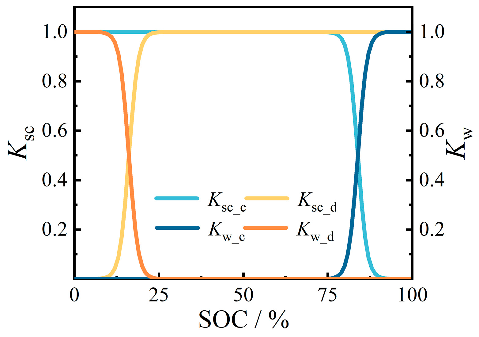
3.2.1. Adaptive Control of SC SOC

This paper divides the SOC for SCs into five intervals, namely, minimum, low, high, and maximum values. To ensure that the SOC does not exceed its limit, an S-type logistic function is employed to establish the charging and discharging curves within [SOCmin, SOClow] and [SOChigh, SOCmax]. The logistic function demonstrates exponential growth in its initial stage, gradually saturates as the value increases, and ultimately converges towards a stable value. The specific expression is provided below.
P ( t ) = K P 0 e r t K + P 0 ( e r t 1 )
where K corresponds to the final value; P0 corresponds to the initial value, and the larger P0, the shorter the time to reach saturation; and r corresponds to an indicator that measures the speed of curve change, and the larger r, the faster the change. The logistic regression function is being incorporated into the allocation coefficient of frequency regulation for DFIG and SC, with SOC as the independent variable and adaptive factors r and P0 as parameter variables. Ksc and Kw are the dependent variables in this context. According to experience, the parameter variable is taken as P0 = 0.01 and r = 15 [14,15]. Therefore, based on SOC feedback, an adaptive parameter expression for SC and DFIG is showed in:
K sc _ c = 1 SOC high > SOC SOC min 0.01 e 15 ( SOC max SOC ) SOC max SOC high 1 + 0.01 ( e 15 ( SOC max SOC ) SOC max SOC high 1 ) SOC max > SOC SOC high 0 SOC SOC max
K sc _ d = 1 SOC low < SOC SOC max 0.01 e 15 ( SOC SOC min ) SOC low SOC min 1 + 0.01 ( e 15 ( SOC SOC min ) SOC low SOC min 1 ) SOC min < SOC SOC low 0 SOC SOC min
where Ksc_c corresponds to the charging coefficient of the SC; Ksc_d corresponds to the discharge coefficient of the SC.
The adaptive parameters of the SC based on SOC feedback are shown in Figure 4, and the wind turbine frequency regulation parameters are determined by Formula (4) accordingly.
K w = 1 K sc

3.2.2. Self-Recovery Control of SOC

As previously mentioned, the frequency regulation responsibility for low-frequency operating conditions is primarily assigned to the SCs. Therefore, the self-recovery control of SOC in SCs is implemented after frequency drop regulation. During periods without frequency regulation, if the frequency stabilizes within the dead band range, power absorption from the grid by SCs continues until SOC reaches 90%. Throughout the charging process, a constant power output is maintained by SCs to ensure maximum charging of SOC and subsequently reduce required energy storage capacity and optimize investment.

3.3. Flow Chart of Primary Frequency Regulation Control Strategy

DFIG and SCs are logically coordinated according to the sequential allocation. Considering that the SC is connected to the DFIG DC bus through the converter, the response speed is millisecond level, and a fast power response can be achieved, while the power response of the wind turbine is relatively lagging, so the charge and discharge of the SC are preferentially involved in the primary frequency regulation.
The DFIG and SC are logically coordinated based on sequential allocation, ensuring efficient power response. Due to the converter connection between the SC and DFIG DC bus, millisecond-level response speed is achieved, enabling a fast power response. In contrast, the wind turbine’s power response lags behind. Therefore, prioritizing the involvement of SC in primary frequency regulation.
Therefore, the flow of primary frequency regulation strategy based on rotor kinetic energy of DFIG and SC is shown in Figure 5. The frequency regulation control is divided into two parts:

3.3.1. High-Frequency Condition

When the grid frequency exceeds the dead band threshold, the wind energy storage system actively engages in frequency regulation. Initially, during Stage I, the SC is charged and its SOC is continuously monitored to determine whether the wind turbine should participate in frequency regulation or not.
If the SOC never exceeds SOChigh, the system will employ virtual inertia control for charging until the end of regulation. However, if SOC surpasses SOChigh, active power support is required from the wind turbine. By referring to real-time calculations based on Formulas (2) and (4), transition coefficients Ksc and Kw are determined using SOC to adjust both SC and DFIG frequency regulation power. Subsequently, in Stage II of the control system, after regulation under high-frequency condition, the wind turbine locks its rotor speed at maximum value while temporarily preserving rotor kinetic energy. A logical judgment is made based on frequency fluctuations within a 60 s cycle. If the frequency decreases, priority is given to releasing the rotor kinetic energy stored in Stage I, and then the frequency regulation process is shifted towards the frequency drop regulation. Alternatively, if no decrease in frequency occurs by the end of 60 s, then the wind turbine releases its rotor kinetic energy and returns to its MPPT.

3.3.2. Low-Frequency Condition

When the grid frequency falls below the dead zone threshold, the wind energy storage system actively participates in frequency regulation for reduction. In Stage I, the SC is discharged first, following a similar approach as under high-frequency condition. Based on the current SOC, it is determined whether the wind turbine should engage in frequency regulation or not.
If the SOC never exceeds SOClow, the energy storage system is discharged using virtual inertia control until the end of frequency regulation. However, if SOC exceeds SOClow, active participation of the wind turbine in frequency regulation becomes necessary. Real-time calculations based on Formulas (3) and (4) are performed to determine transition coefficients Ksc and Kw, which are utilized for adjusting both the energy storage system and the wind turbine’s power contribution to frequency regulation based on SOC.
Following the aforementioned two cases of regulation, both enter Stage II of low-frequency condition. The frequency fluctuation is continuously monitored for logical assessment. If it remains stable within the designated frequency dead zone for a duration of 30 s, constant power charging is implemented to restore the SOC in the SC. Conversely, if any deviation in frequency occurs, an immediate transition to the corresponding frequency regulation state takes place.

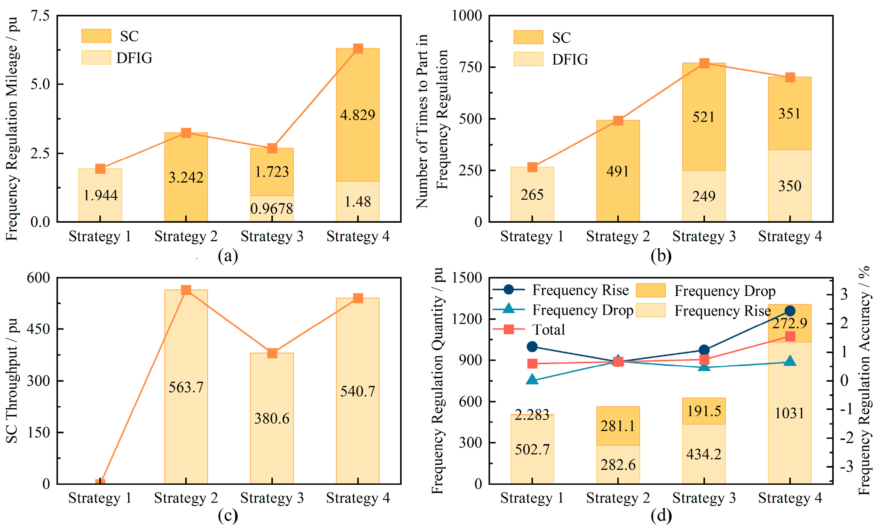
3.4. Simulation Evaluation Indicators

In order to evaluate the effectiveness and economy of the frequency regulation strategy proposed in this paper and the contribution of frequency regulation resources, the following indexes are defined:
  • Frequency regulation mileage: the total absolute value of the output power change of a frequency regulation resource in a period is defined as the “frequency regulation mileage” of the resource [16]. The frequency regulation mileage is calculated as follows:
M = k P k + 1 P k
2.
Frequency regulation accuracy: define the ratio of the integral between the actual output and the frequency regulation demand instruction in a frequency regulation process as frequency regulation accuracy.
H = P s d t P o d t
where Ps is the actual output; Po is the frequency regulation demand power instruction.
3.
Frequency regulation integral power contribution index: according to the standard requirements, define the wind turbine primary frequency regulation integral power contribution index q as follows:
q = K 15 × q 15 + K 30 × q 30 + K 45 × q 45
where K15, K30, and K45 are the power contribution index weights of the wind turbine for 15 s, 30 s, and 45 s, which are set as 0.55, 0.3, and 0.15, respectively; q15, q30, and q45 are first frequency regulation integral power contribution indexes of the wind turbine for 15 s, 30 s, and 45 s, respectively.

4. Simulation Verification

4.1. Simulation Model

In this paper, based on the Matlab/Simulink simulation platform, the wind storage co-simulation model as shown in Figure 6 was built to verify the feasibility of the control strategy. Among them, the rated power of DFIG is 1.5 MW, the rated wind speed is 11 m/s, and the SC capacity is 150 KW × 80 s. Table 1. lists the relevant parameters of the wind turbine.
Where Pm corresponds to the input mechanical power of the wind turbine; Ps, Qs correspond to the active and reactive power on the stator side of DFIG; Pr, Qr correspond to the active and reactive power on the rotor side; Pg, Qg correspond to the active and reactive power output from the grid side converter to the grid connection point; and PA, QA correspond to the total power transmitted by DFIG to the grid connection point.

4.2. Simulation of Short-Term Fluctuation in System Frequency

To verify the feasibility of the proposed strategy, the simulation was carried out under a constant wind speed of 10 m/s. The following conditions were alternately implemented:
  • High-frequency conditions;
  • Low-frequency conditions;
  • High-frequency conditions followed by low-frequency conditions;
  • Low-frequency conditions followed by high-frequency conditions.

4.2.1. Single Frequency Fluctuation

The simulation conditions of frequency rise fluctuation are as follows: the frequency fluctuation is set at 50 s; the peak frequency deviation reaches 0.14 Hz; the whole fluctuation duration lasts for 40 s; the initial SOC of the SC is set to 70%. The results of the fluctuation response by the joint control strategy of wind turbine and SC are presented in Figure 7. In Figure 7, Pref corresponds to the reference power calculated based on traditional virtual inertia control.
The charging priority of the SC is based on the availability of a charging margin, as depicted in Figure 7. Once SOC > 70%, the wind turbine increases its rotor speed to absorb energy and stabilizes it at maximum capacity. Subsequently, when the frequency reaches stability within the dead zone, the wind turbine releases its stored kinetic energy. As per Formula (6), this results in a frequency regulation integral power contribution index of 1.208, thereby providing enhanced active power support to the power grid.
The process under low-frequency conditions is similar to that on the high-frequency side, as shown in Figure 8. After the frequency drops, the SC gives priority to discharge and undertakes the main frequency regulation task. Because the SOC is enough to meet the frequency regulation demand, the wind turbine does not participate in frequency regulation. The frequency regulation integral power contribution index is 0.998, which can meet the demand for primary frequency regulation.

4.2.2. Successive Frequency Fluctuations

The feasibility of the frequency regulation strategy was verified by setting short-term continuous fluctuations. The simulation conditions of successive frequency fluctuations are as follows: the first frequency fluctuation is set at 50 s; the peak frequency deviation reaches 0.14 Hz; the second opposite frequency fluctuation is set at 120 s; the whole fluctuation duration lasts for 40 s; the initial SOC of the SC is set to 70%. Figure 9 shows the resulting waving for the joint control strategy of DFIG and SC.
It can be seen from Figure 9 and Figure 10 that the response of the combined DFIG and SC system meets expectations. Among them, it is worth mentioning that in Figure 9, according to the analysis of Section 2, the low-frequency conditions are followed by high-frequency conditions, and the wind turbine preferentially releases the rotor kinetic energy stored in the last frequency regulation, and then the SC discharges. The proportion of kinetic energy released by the wind turbine in the second frequency regulation reaches 22.34%, which significantly reduces the output and discharge depth.

4.3. Simulation of Long-Term Fluctuation of System Frequency under Fixed Wind Speed

To further verify the effectiveness of the proposed strategy in long-term conditions, a 24 h simulation was carried out under random frequency fluctuations, as shown in Figure 11, with the wind speed constant at 6 m/s. The simulation results are shown in Figure 11. In addition, to verify the superiority of the strategy by horizontal comparison, the following traditional strategies were implemented:
  • Strategy 1: DFIG frequency regulation alone;
  • Strategy 2: SC frequency regulation alone;
  • Strategy 3: DFIG and SC fixed coefficient distribution frequency regulation;
  • Strategy 4: combined adaptive frequency regulation proposed in this paper.
The wind turbine alone, as depicted in Figure 11, is unable to provide sufficient frequency support for the system. As shown in Figure 12, at a constant wind speed of 6 m/s, the wind turbine operates consistently near its lower limit and cannot actively participate in regulating frequency drops. Consequently, Strategy 1 exhibits an almost negligible adjustment amount and accuracy under the low-frequency condition. In contrast, the bidirectional adjustment capability of the SC enables it to offer support for both upward and downward frequency fluctuations. Therefore, Strategy 2 engages nearly twice as often in frequency regulation compared to Strategy 1; it also covers a greater frequency regulation mileage during such regulation by approximately 66.8%. Additionally, the frequency regulation integral power contribution index increases by 11.6%. However, due to limitations imposed by its configured capacity, the SC’s ability to provide frequency support results in only a relatively modest increase in frequency regulation quantity.
The charging and discharging times of the SC in Strategy 3 are increased by 48% compared to Strategy 4, as a result of the DFIG and SC participating in frequency regulation parallelly. However, it is observed that the frequency regulation capacity provided by Strategy 3 does not exhibit a corresponding increase, leading to a reduction in ultracapacitor throughput by 29.7% compared to Strategy 4. This can be attributed to the fixed allocation coefficient’s inability to dynamically adjust according to SOC and its lack of flexibility when there is a margin for frequency regulation.
From Figure 12, the wind storage joint adaptive frequency regulation strategy has a 108.4% increase in frequency regulation capacity compared to Strategy 3 under the same SC configuration. At the same time, compared to Strategy 2, it reduces the charging and discharging times and throughput and improves the life of SC.
The frequency regulation strategy based on DFIG and SC exhibits a 108.4% increase in frequency regulation capacity compared to Strategy 3, while maintaining the same SC configuration. Additionally, it reduces charging and discharging times and throughput, thereby enhancing the SC’s lifespan when compared to Strategy 2.

4.4. Simulation of Long-Term Fluctuation of System Frequency under Variable Wind Speed

In order to further validate the superiority of the proposed strategy and its universality across diverse conditions, a 24 h simulation was conducted with randomly variable wind speeds. The wind speeds ranged from 6 m/s to 10 m/s and were updated at random intervals of 10 min, as depicted in Figure 13. The frequency variation followed the same pattern as described in Section 4.3. The simulation results are presented in Figure 13. Similar to Section 4.3, comparative simulations were performed between this strategy and traditional frequency modulation strategies, with the outcomes illustrated in Figure 14.
Compared to Figure 12, Figure 14 exhibits a similar trend of change; however, the magnitude of improvement is relatively modest. Consequently, the primary analysis focuses on assessing the impact of wind speed variations on the frequency regulation efficacy of different strategies. Due to stochastic fluctuations in wind speed within the range of 6–10 m/s, all values surpassing 6 m/s result in corresponding increases in rotor speed, thereby endowing wind turbines with greater regulatory capacity during low-frequency conditions. Consequently, when compared to a wind speed of 6 m/s, Strategy 1 demonstrates an almost twofold increase in both frequency regulation mileage and participation frequency under variable wind speeds.
By using SCs to provide active power support under low-frequency conditions, Strategy 4 has increased the frequency regulation accuracy of low-frequency conditions by 7%. Although the advantages of the strategy proposed at moderate wind speeds are lower than at low wind speed, according to annual actual wind speed statistics, less than 10% of the operating conditions have wind speeds exceeding 80% or more of the rated wind speed of the wind turbines [13].
However, as previously analyzed, the regulating capability of wind turbines under low-frequency conditions remains limited, and the frequency regulation accuracy of Strategy 1 can only reach 80% under such conditions. By employing SCs for active power support during low-frequency scenarios, Strategy 4 has enhanced the frequency regulation accuracy by an additional 7%. Although the advantages of this proposed strategy are comparatively lower at moderate wind speeds than at low wind speeds, it is worth noting that less than 10% of operational circumstances experience wind speeds exceeding 80% or more of the rated speed [13]. Therefore, the proposed frequency regulation control strategy remains effective in most cases.

5. Conclusions

The objective of this study is to enhance the frequency regulation effectiveness of DFIG and SC collaborative frequency regulation while reducing the energy storage configuration costs. Based on an analysis of wind turbine frequency regulation characteristics, this paper proposes an adaptive frequency regulation control strategy based on rotor kinetic energy of DFIG and SC. Theoretical analysis and simulation verification lead to the following conclusions:
  • From the perspective of long-term energy management in working conditions, this paper proposes a speed control strategy for wind turbines that maximizes the utilization of the over speed operating range on the right side of the MPPT point. This approach aims to enhance frequency regulation resources and achieve significant economic benefits;
  • The joint control strategy considers the real-time state setting and adaptive allocation parameters of the SOC, effectively addressing sudden changes during the transition period of multiple frequency regulation resource switching and preventing overcharging and discharging. In conjunction with rotor kinetic energy management, it provides greater flexibility in capacity configuration for SC, thereby facilitating a reduction in initial investment.

Author Contributions

Conceptualization, R.M., S.Y. and X.L.; methodology, R.M., S.Y. and X.L.; validation, S.G.; formal analysis, S.G.; investigation, S.G.; resources, R.M., S.Y. and X.L.; writing—original draft preparation, S.G.; writing—review and editing, R.M., S.Y., X.L., S.G., X.Y. and J.J.; supervision, X.Y. and J.J.; project administration, R.M., S.Y., X.L., X.Y. and J.J.; funding acquisition, R.M., S.Y., X.L., X.Y. and J.J. All authors have read and agreed to the published version of the manuscript.

Funding

This research was funded by Research Project of Central South Electric Power Testing and Research Institute of China Datang Corporation Science and Technology Research Institute, grant number 10001278D22KYFY00005; National Natural Science Foundation of China, grant number 52207102.

Data Availability Statement

Data are contained within the article.

Conflicts of Interest

Authors Renting Ma, Shitong Yuan and Xianwei Li were employed by Central South Electric Power Test and Research Institute, China Datang Corporation Science and Technology Research Institute. The remaining authors declare that the research was conducted in the absence of any commercial or financial relationships that could be construed as a potential conflict of interest.

References

  1. Junhui, L.; Tao, H.; Gang, M.; Gangui, Y.; Cuiping, L.; Dacheng, H. Primary frequency regulation strategy with energy storage system based on weight factors and state of charge recovery. Autom. Electr. Power Syst. 2020, 44, 63–72. [Google Scholar]
  2. Behabtu, H.A.; Messagie, M.; Coosemans, T.; Berecibar, M.; Anlay Fante, K.; Kebede, A.A.; Mierlo, J.V. A review of energy storage technologies’ application potentials in renewable energy sources grid integration. Sustainability 2020, 12, 10511. [Google Scholar] [CrossRef]
  3. Behabtu, H.A.; Coosemans, T.; Berecibar, M.; Fante, K.A.; Kebede, A.A.; Mierlo, J.V.; Messagie, M. Performance evaluation of grid-connected wind turbine generators. Energies 2021, 14, 6807. [Google Scholar] [CrossRef]
  4. Behabtu, H.A.; Vafaeipour, M.; Kebede, A.A.; Berecibar, M.; Van Mierlo, J.; Fante, K.A.; Messagie, M.; Coosemans, T. Smoothing Intermittent Output Power in Grid-Connected Doubly Fed Induction Generator Wind Turbines with Li-Ion Batteries. Energies 2023, 16, 7637. [Google Scholar] [CrossRef]
  5. Hui, L.; Jun, G.; Yu, G.; Hanmin, L.; Fei, X. Optimization scheme selection of wind farm participation in grid primary frequency modulation and study of wind-storage coordination control strategy. J. Glob. Energy Interconnect. 2019, 2, 44–52. [Google Scholar]
  6. Razzhivn, I.A.; Rudnik, V.E.; Bay, Y.D.; Kievec, A.V. Coordinated control of a hybrid type 3 wind turbine and hydrogen energy storage model to provide efficient frequency control. Int. J. Hydrog. Energy 2022, 47, 35947–35958. [Google Scholar] [CrossRef]
  7. Wenqiang, Y.; Bin, C. Research on the configuration method & tool for the hybrid energy storage system on the power generation side. Energy Storage Sci. Technol. 2022, 11, 3246–3256. [Google Scholar]
  8. Hongyan, F. Research on Control Strategy of Hybrid Energy Storage Participating in System Frequency Modulation; Qingdao University: Qingdao, China, 2022. [Google Scholar]
  9. Xia, D.; Wei, S.; Haiwei, X. Integrated control strategy of battery energy storage system in primary frequency regulation. High Volt. Eng. 2018, 44, 1157–1165. [Google Scholar]
  10. Tianpei, Z.; Wei, S. Study on virtual inertia control for DFIG-based wind farms with high penetration. Proc. CSEE 2017, 37, 486–496. [Google Scholar]
  11. Xilin, Z.; Pin, L.; Bo, F. Primary frequency regulation control strategy with wind-storage cooperation based on multi-objective optimization. South. Power Syst. Technol. 2022, 16, 68–76. [Google Scholar]
  12. DL/T 1870–2018; Technical Specification for Power Grid and Source Coordination. National Energy Administration: Beijing, China, 2018.
  13. Chao, Z. A Power System Unit Combination Strategy Considering Overspeed Load Shedding and Inertia Control of Wind Turbines; Northeast Electric Power University: Jilin, China, 2021. [Google Scholar]
  14. Zhihui, M.; Xinran, L.; Zhuangxi, T.; Jiyuan, H.; Li, H. Integrated control of primary frequency regulation considering dead band of energy storage. Trans. China Electrotech. Soc. 2019, 34, 2102–2115. [Google Scholar]
  15. Ruo, L.; Xinran, L.; Zhangxi, T.; Jiyuan, H.; Zhihui, M. Interated control strategy considering energy storage battery pareticipating in secondary frequency regulation. Autom. Electr. Power Syst. 2018, 42, 74–82. [Google Scholar]
  16. Zechun, H.; Xu, X.; Fang, Z.; Jing, Z.; Yonghua, S. Research on automatic generation control strategy incorporating energy storage resources. Proc. CSEE 2014, 34, 5080–5087. [Google Scholar]
  17. Yi, L.; Yuchen, T.; Xunjun, C.; Hai, H.; Fengzhou, S.; Quanyuan, J. A voltage ride-through control based on coordination between energy storage and wind turbine. Modern Electric Power. 2023, 40, 788–796. [Google Scholar]
Figure 1. Wind turbine maximum power point tracking curve.
Energies 17 00331 g001
Figure 2. Block diagram of DFIG control strategy.
Energies 17 00331 g002
Figure 3. Block diagram of SC control strategy.
Energies 17 00331 g003
Figure 4. Partition coefficient curve based on logistic function.
Energies 17 00331 g004
Figure 5. Flow chart of primary frequency regulation strategy based on rotor kinetic energy of DFIG and SC.
Energies 17 00331 g005
Figure 6. Single DFIG and SC joint system.
Energies 17 00331 g006
Figure 7. Frequency response under high−frequency conditions: (a) Frequency curve in high−frequency conditions; (b) Wind turbine rotor speed response; (c) Actual power and reference power of wind storage system grid connection points; (d) Wind turbine primary frequency regulation power; (e) State of charge of SC; (f) SC output power.
Energies 17 00331 g007
Figure 8. Frequency response under low−frequency conditions: (a) Frequency curve in high−frequency conditions; (b) Wind turbine rotor speed response; (c) Actual power and reference power of wind storage system grid connection points; (d) Wind turbine primary frequency regulation power; (e) State of charge of SC; (f) SC output power.
Energies 17 00331 g008
Figure 9. Frequency response under low−frequency conditions followed by high-frequency conditions: (a) Frequency curve in high−frequency conditions; (b) Wind turbine rotor speed response; (c) Actual power and reference power of wind storage system grid connection points; (d) Wind turbine primary frequency regulation power; (e) State of charge of SC; (f) SC output power.
Energies 17 00331 g009
Figure 10. Frequency response under high−frequency conditions followed by low-frequency conditions: (a) Frequency curve in high−frequency conditions; (b) Wind turbine rotor speed response; (c) Actual power and reference power of wind storage system grid connection points; (d) Wind turbine primary frequency regulation power; (e) State of charge of SC; (f) SC output power.
Energies 17 00331 g010
Figure 11. (a) Response of the proposed frequency regulation control from 0 to 12 h under fixed wind speed; (b) response of the proposed frequency regulation control from 12 to 24 h under fixed wind speed.
Energies 17 00331 g011
Figure 12. Comparison of four frequency regulation strategy indicators: (a) Frequency regulation mileage; (b) Number of times to part in frequency regulation; (c) SC throughput; (d) Frequency regulation quantity.
Energies 17 00331 g012
Figure 13. (a) Response of the proposed frequency regulation control from 0 to 12 h under variable wind speed; (b) response of the proposed frequency regulation control from 12 to 24 h under variable wind speed.
Energies 17 00331 g013
Figure 14. Comparison of four frequency regulation strategy indicators under variable wind speed: (a) Frequency regulation mileage; (b) Number of times to part in frequency regulation; (c) SC throughput; (d) Frequency regulation quantity.
Energies 17 00331 g014
Table 1. Wind turbine parameters [17].
Basic Parameters of Wind Turbine
Stator resistance (pu)0.00706
Stator inductance (pu)0.171
Rotor resistance (pu)0.005
Rotor inductance (pu)0.156
Magnetizing inductance (pu)2.9
Inertia time constant (s)5.04
Disclaimer/Publisher’s Note: The statements, opinions and data contained in all publications are solely those of the individual author(s) and contributor(s) and not of MDPI and/or the editor(s). MDPI and/or the editor(s) disclaim responsibility for any injury to people or property resulting from any ideas, methods, instructions or products referred to in the content.

