Article

Evaluation of Ethylene-Vinyl Acetate, Methyl Methacrylate, and Polyvinylidene Fluoride as Encapsulating Materials for Perovskite-Based Solar Cells, Using the Low-Temperature Encapsulation Method in a Cleanroom Environment

by
Luis Ocaña
1,2,*,
Carlos Montes
1,2,
Benjamin González-Díaz
2,
Sara González-Pérez
3 and
Elena Llarena
1
1
Instituto Tecnológico y de Energías Renovables, S.A. (ITER), 38600 Santa Cruz de Tenerife, Spain
2
Departamento de Ingeniería Industrial, Escuela Superior de Ingeniería y Tecnología, Universidad de La Laguna (ULL), 38200 Santa Cruz de Tenerife, Spain
3
Departamento de Didácticas Específicas, Universidad de La Laguna (ULL), 38200 Santa Cruz de Tenerife, Spain
*
Author to whom correspondence should be addressed.
Energies 2024, 17(1), 60; https://doi.org/10.3390/en17010060
Submission received: 5 December 2023 / Revised: 12 December 2023 / Accepted: 19 December 2023 / Published: 21 December 2023

Abstract

:
In this article, the development of a stable perovskite-based photovoltaic device manufactured in a controlled environment, with humidity between 40 and 65%, and encapsulated is presented. Encapsulation using polymers like ethylene-vinyl acetate (EVA), polymethyl methacrylate (PMMA), and EVA combined with polyvinylidene fluoride (PVDF) was proposed due to the low curing temperatures, insulating properties, and simple deposition processes of these materials. Testing involved subjecting these materials to humidity, temperature, and UV irradiation, following the International Summit on Stability of Organic Photovoltaics (ISOS-T) protocols, and using a 24 W UV lamp. Characterization analyses were carried out using various technologies including digital microscopy, spectroscopic ellipsometry, Fourier-transform infrared spectroscopy and electrical simulations. The results indicate that EVA-encapsulated samples displayed higher stability and resistance against external factors compared to PMMA and EVA-PVDF. Specifically, the EVA-encapsulated samples maintained a 15.06% power conversion efficiency (PCE) after the thermal cycles were carried out, reducing only by 0.9% compared to pristine samples. Similarly, after 350 h of UV exposure, they retained a PCE of 13.90%, decreasing by just 9.58% compared to the initial value.

1. Introduction

Currently, perovskite-based solar cells (PSCs) stand out for their rapid increase in energy efficiency [1] along with their high instability [2,3]. Their straightforward manufacturing processes, relying on simple deposition methods and the use of basic reagents, combined with their high energy conversion capabilities, due to their extensive absorption capacity and low carrier recombination rates, position them as an emerging technology with significant potential for market integration.
Presently, these devices achieve efficiencies of 26.1% for perovskite cells [4], 33.9% for tandem cells composed of perovskite and silicon, and 18.6% for modules, as per the latest table published by NREL [1,5]. However, a stable device capable of maintaining its properties has not yet been achieved. The main stability issues stem from their interaction with water (H2O), oxygen (O2), ultraviolet light (UV), high temperatures (T), and bias current (Bias) [2,3].

1.1. Degradation Mechanisms

Among the various agents causing degradation, water stands out as the most detrimental, necessitating stringent protection measures for perovskite-based photovoltaic devices [2,3]. The deleterious impact of moisture on perovskite layers escalates progressively with exposure time [2,6]. Initially, at around 20% relative humidity (RH), minimal degradation occurs [6], but as RH reaches 40%, observable changes in layer coloration become evident [7,8]. Furthermore, in environments with RH between 80% and 100%, complete decomposition occurs within a mere 6 h exposure window [2,6]. Thus, degradation in the perovskite layers initiates at grain boundaries under low relative humidity conditions and extends inward as humidity levels rise [7,9,10]. Additionally, several studies have shown that ion migration induced by moisture is a significant factor in reducing the efficiency of PSCs [2,11].
Two additional factors, in conjunction with water, expedite the degradation process. Firstly, oxygen plays a role in the degradation by contributing to the decomposition of hydrogen iodide, leading to the formation of iodine and water molecules [3,12]. Secondly, light, particularly UV irradiation, accelerates the decomposition of hydrogen iodide into iodide, dihydrogen, and diiodine [3,13]. These light-induced mechanisms are attributable to several factors, including light-activated trap states [2,14,15], photoinduced ion segregation [2,15,16,17], photoinduced atom/ion migration [2,18], or photodecomposition [2,19,20]. Various studies propose equations suggesting the formation of NH3, HI, and I2 with hydrocarbon species on the surface after MAPbI3 decomposition [2,21,22,23], while others suggest the formation of volatile products such as CH3NH2, HI, and I2 [2,24,25].
Temperature is another factor influencing the degradation of perovskite-based devices. Some researchers [26,27] assert that the MAPbI3 layer undergoes a phase transition from tetragonal to cubic at temperatures approximately 56 °C, well within the operational limits of a photovoltaic module [26,27]. Additionally, it has been observed that prolonging curing durations at temperatures below 80 °C triggers the decomposition process, which becomes irreversible upon the tetragonal-to-cubic phase transition [28,29]. Meanwhile, another study [30] suggests that prolonged curing at temperatures exceeding 100 °C leads to MAPbI3 decomposition [30,31,32]. Eperon et al. demonstrated decomposition occurring beyond 150 °C, noting a transition in the MAPbI3 layer color from dark brown to yellow within a few hours [33,34].
Therefore, it is crucial, considering that during their exposure to sunlight, that perovskite-based devices reach operating temperatures between 50 °C and 60 °C. Currently, established tests to estimate their resilience include thermal cycling tests (from −45 °C to +85 °C) and damp heat tests (85 °C; 85% RH), established by various standards, depending on the technology, such as the UNE-EN 61646 standard for thin-film photovoltaic module testing, the UNE-EN 61215 standard for crystalline silicon photovoltaic module testing, or the protocols from the International Summit on Stability of Organic Photovoltaics (ISOS) for perovskite cells.

1.2. Aim and Scope

For this reason, there is a clear need to enhance the stability of photovoltaic devices based on perovskite. In this context, the present research proposes the use of the low-temperature encapsulation method [35] with polymers as a path to improve the stability of perovskite solar cells (PSCs) manufactured in a clean room environment. Thanks to their chemical versatility, the possible applications of organic polymers within perovskite solar devices have been highly diversified as charge-transporting materials, of either hole or electrons, or as additives, these being blended into the designed layer or used as a buffer layer [36], becoming an interesting material to include in PSC architectures. Various polymeric encapsulating materials such as ethylene-vinyl acetate (EVA), polymethyl methacrylate (PMMA), and a combination of ethylene-vinyl acetate with polyvinylidene fluoride (EVA-PVDF) have been evaluated to determine the most suitable polymer for enhancing the stability of devices manufactured in cleanroom environments and at relative humidities between 40% and 65%.
Polymer encapsulation allows the isolation of devices from both water vapor and oxygen, improving their resistance against degradation caused by solar irradiation, temperature, and humidity [37]. Despite numerous studies on PSC stability [37,38], comparing these studies is imprecise due to the lack of standardized analysis. Therefore, this work proposes a stability study based on protocols established by the International Summit on Stability of Organic Photovoltaics (ISOS) to standardize comparative studies related to perovskite solar cell stability. Additionally, it aims to assess stability against UV irradiation, complementing previously published studies, where the effect of UV irradiation on the degradation of perovskite layers was already established [35].
This study was divided into three phases: during the first phase, samples underwent degradation tests; in the second phase, optical characterization was performed using digital microscopy, spectroscopic ellipsometry and Fourier-transform infrared spectroscopy (FTIR). Finally, in the third phase, simulations with the optical characterization results were carried out. For this purpose, the SCAPS-1D software [39,40,41,42,43,44] was employed to evaluate the impact of humidity, temperature, and ultraviolet irradiation on the complete photovoltaic devices.

2. Materials and Methods

2.1. Sample Preparation

All manufacturing processes were conducted within an ISO 7 cleanroom, maintaining a constant temperature of 23 °C and a relative humidity (RH) between 40% and 60%. Due to the significant influence of temperature and humidity on these devices, continuous monitoring of these parameters was carried out at all times.
The substrate preparation involved, initially cutting 300 mm × 300 mm × 2 mm soda lime silica glass sheets into 25 mm × 25 mm pieces using a Camag SmartCUT glass cutter. These pieces served as substrates for perovskite layer deposition and as cover glasses to seal the encapsulation.
Subsequently, the substrates underwent ultrasonic cleaning using the HD 5L-JP Selecta equipment. This cleaning procedure consisted of five phases using an ultrapure hot water bath with a resistivity of 18 MΩ·cm at 25 °C and <5 ppb of total organic carbon (TOC) for rinses between phases. In phase 1, the substrates were placed in a staining container filled with a soapy solution composed of 2% Hellmanex (Z805939; Sigma Aldrich, St. Louis, MO, USA) for 10 min at 40 °C. In phase 2, the substrates were placed in a staining container filled with ultrapure hot water (18 MΩ∙cm) for 10 min at 40 °C. In phase 3, the substrates were placed in a staining container filled with acetone (179124; Sigma Aldrich) for 10 min at 40 °C. In phase 4, the substrates were placed in a staining container filled with isopropyl alcohol (≥98%; 20,922.466; VWR) for 10 min at 60 °C. Finally, nitrogen (N2; 99.998%) was used to dry the substrates, employing a precision metal clamp (232–2113; VWR) to hold them during the drying process, which solely aims to remove water.
Following this, a second cleaning step involving UV and ozone was performed using the Ossila L2002A2-EU equipment. This procedure aims to eliminate surface organic contaminants from the samples to enhance the interface between the substrate and the perovskite layer [45,46]. The process involves exposing the samples to combined UV irradiation and ozone effects for a period of 20 min at a temperature of 23 °C [47].
Finally, the deposition area on the glass substrate was delimited to keep the sample perimeter free, enhancing its insulation against moisture. This perimeter setback was precisely executed by using Kapton tape to define the deposition region, meticulously removed before the sample initiates the curing process.

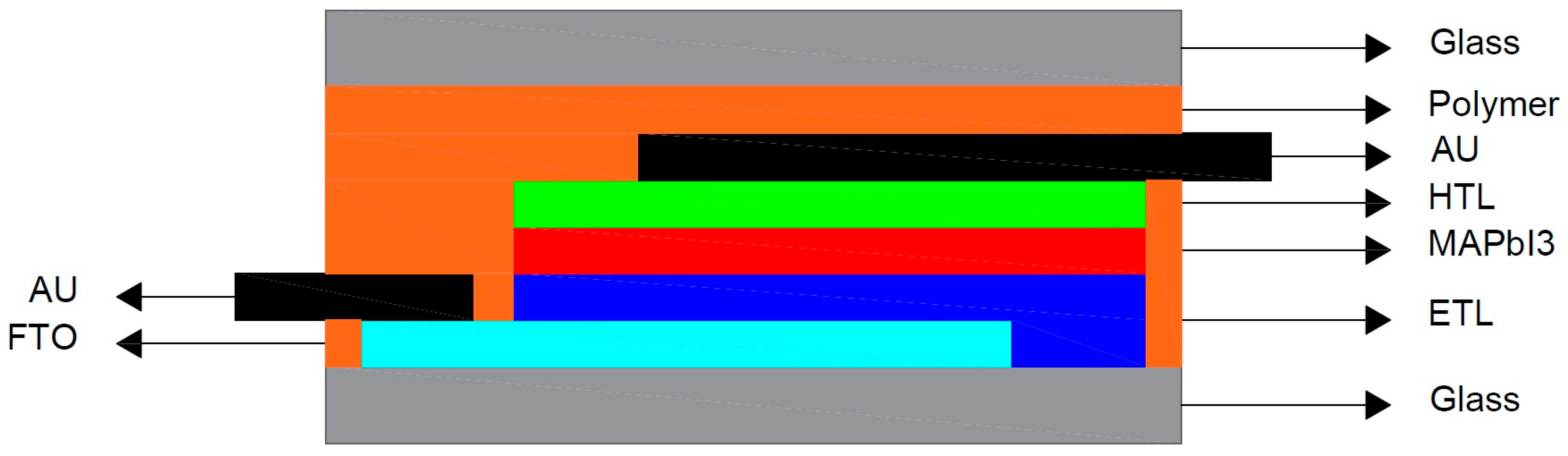
2.2. Synthesis and Sample Fabrication

Below, the process conducted to synthesize perovskite is described, divided into 5 phases. To carry out this process, a heated magnetic stirrer (Ovan, basicMagMix), an unheated magnetic stirrer (LBX Instruments, S03D), a precision balance (Sartorius Entris 124i-1S), and variable-volume pipettes were used. During the first phase, 0.7434 g of lead iodide (PbI2, Sigma Aldrich 211168, St. Louis, MO, USA) was dissolved in a 9:1 (v/v) solution of 1.148 µL N,N-dimethylformamide (DMF, 99.8%, Sigma Aldrich 227056) and 127.6 µL dimethyl sulfoxide (DMSO 99.9%, Sigma Aldrich 276855) for 30 min at 300 rpm and at a temperature of 75 °C [48]. In the second phase, 0.2598 g of methylammonium iodide (CH3NH3I, MAI 98%, TCI M2556) was added to the previous solution to reach a 1:1 molar concentration. It was mixed for 20 min at 300 rpm and a temperature of 75 °C [48]. In the third phase, the solution was left to cool for 60 min at 300 rpm and at a temperature of 23 °C [48]. In the fourth phase, the solution was filtered using a polytetrafluoroethylene (PTFE) filter (DDF02T1750; Fisher Scientific) with a pore size of 0.22 µm [49]. Finally, in the fifth phase, the synthesis was maintained at a speed of 300 rpm and at a temperature of 23 °C throughout the manufacturing process. Table 1 details the quantities used to prepare the perovskite layer synthesis.
Once the synthesis of the perovskite layer had been prepared, the phase of its deposition onto the silica glass “soda line” substrate of 25 mm × 25 mm × 2 mm began. This step was carried out inside the wafer centrifuge chamber (Navson, model NT12000), where a controlled environment was set with a relative humidity between 8 and 10%, by introducing a continuous flow of clean and dry air. The deposition was conducted in a static mode: 100 µL of the synthesis was carefully pipetted onto the substrate. After 3 s, the centrifuge holder starts moving, rotating at a speed of 5000 rpm. After 10 s from the start of the rotation, a specific amount of 300 µL of chlorobenzene, a high-purity non-polar solvent (284513, 99.8%, Sigma Aldrich), was precisely introduced, this time in dynamic mode. This addition aims to promote optimal crystallization of the MAPbI3 layer. Finally, the deposition process halted at 30 s, achieving the formation of a thin layer with a uniform thickness of 300 nm [48]. This procedure ensures obtaining perovskite layers with optimal properties for the specific objectives of this study.
Upon completion of the layer deposition process, the sample was carefully transferred, using precision metal tweezers, to the drying oven, a Coterm JP Selecta model. In this crucial step of the process, the sample undergoes a thermal treatment at a constant temperature of 100 °C, extending this step for a duration of 10 min. This careful heating enables controlled evaporation of the solvents used during deposition, while promoting optimal crystallization of the deposited layer. The importance of this drying step was substantial as it significantly contributes to the consolidation and stabilization of the structure. This process ensures the successful formation of the perovskite layer, maintaining its properties and a uniform structure, optimally preparing it for the subsequent steps of the process.
Once the deposition and curing processes of the samples were completed, an additional essential step was executed for their optimal preservation before encapsulation. The samples were immediately stored in a vacuum desiccator (Normax, Lda), shielded in darkness, and completely isolated from oxygen and moisture. The significance of this procedure lies in its ability to prevent any possible degradation of the samples, ensuring they retain their intrinsic properties without undergoing unwanted alterations, guaranteeing they were ready for future analysis or experimentation phases.

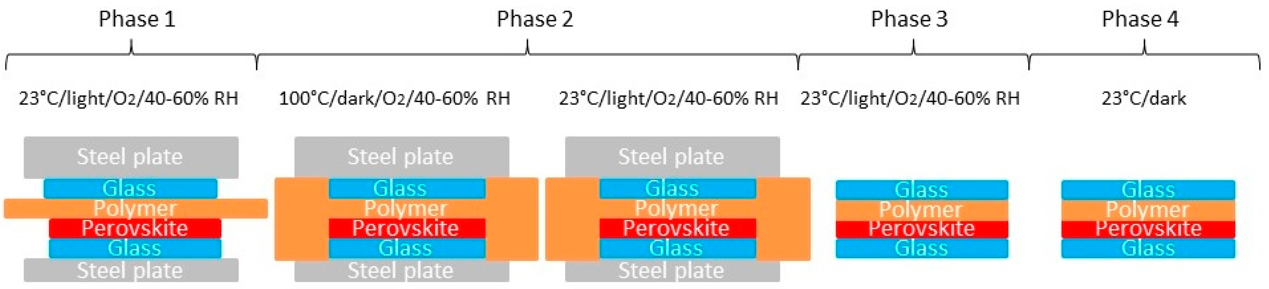
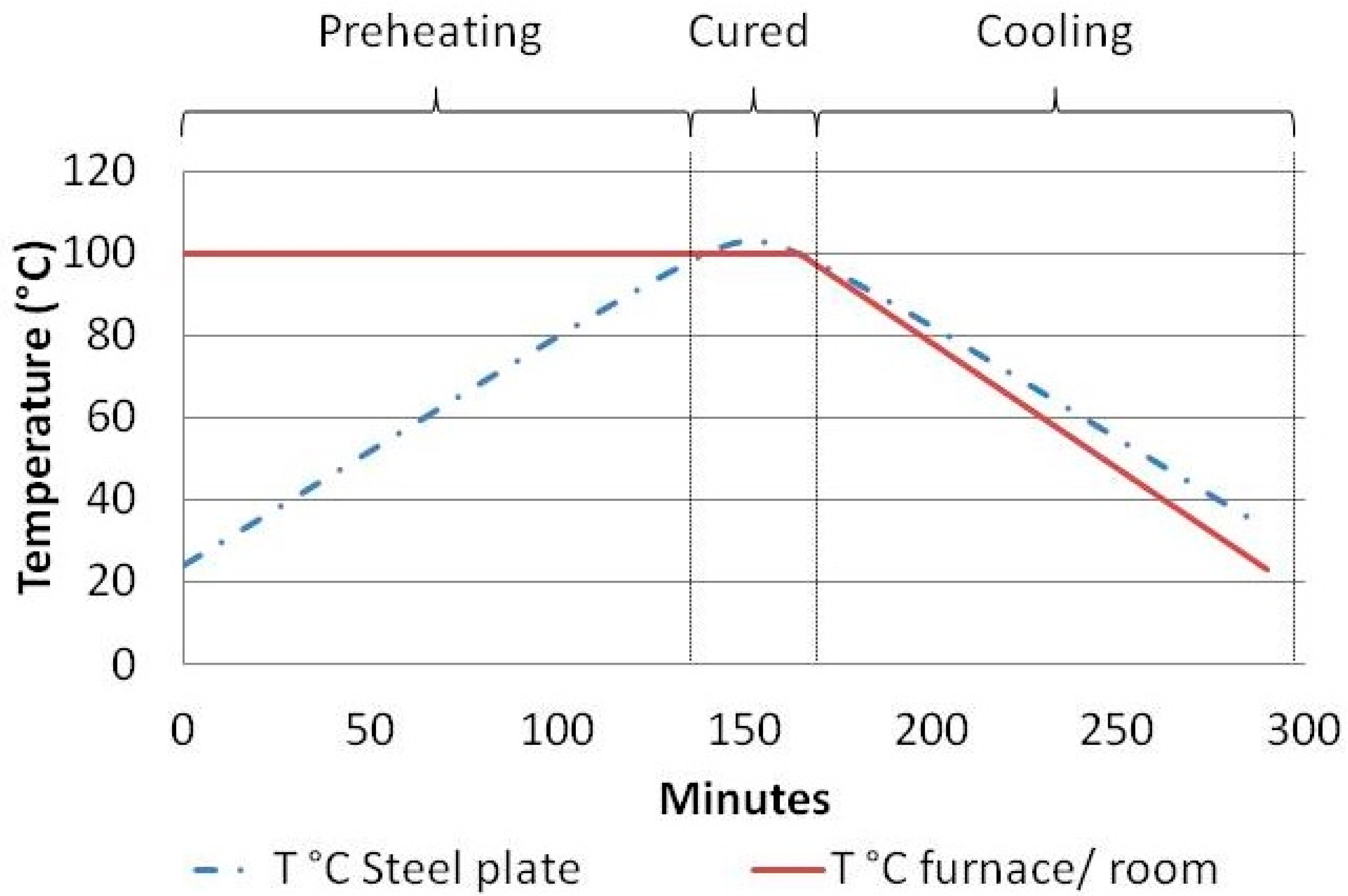
2.3. Encapsulation of the Samples

The encapsulation process (Figure 1), like the rest of the manufacturing process, takes place inside the cleanroom, with a relative humidity between 40 and 60% and a temperature of 23 °C. It was divided into 4 phases, utilizing two steel plates of 200 mm × 200 mm, a drying oven (Coterm JP Selecta 2000208), and a vacuum desiccator (Normax, Lda).
During phase 1, the assembly of the samples on the 200 mm × 200 mm × 3 mm steel plate was carried out. First, each glass substrate with the MAPbI3 layer deposited was placed on the steel plate. Second, the polymer material under study was placed on the plate. Each of these polymers was distinguished by the deposition technique used for applying the encapsulating material sheet:
  • The EVA sheet (Encapsolar PC-135A, Stevens Urethane, Easthampton, MA, USA), measuring 30 mm × 30 mm, was directly placed onto the perovskite layer;
  • The PMMA sheet was formed by depositing a solution of 200 µL statically, directly onto the perovskite layer. The solution was prepared with a concentration of 10:90 by weight (wt%), by mixing 0.874 g of PMMA (Alfa Aesar, Thermo Fisher Kandel GmbH) in 7 mL of chlorobenzene (284513, 99.8%, Sigma Aldrich);
  • The sheet composed of EVA (Encapsolar PC-135A, Stevens Urethane, Easthampton, MA, USA) and PVDF (X 3M 8590M Deutschland GmbH), measuring 30 mm × 30 mm, was directly placed onto the perovskite layer.
Once the encapsulating material was in place, the third step involved placing the cover glass over the chosen polymer. Fourth, the assembly formed by the glass substrate, the polymer, and the cover glass was fixed to the supporting steel plate using adhesive tape (51408; Kapton tape). Fifth, a steel plate measuring 200 mm × 200 mm × 15 mm (10 kg) was placed on the samples to exert homogeneous pressure during the encapsulation process.
During phase 2, the thermal encapsulation process was carried out. The samples with the steel plates were placed in the drying oven at 100 °C for 165 min. As seen in Figure 2, the steel plate takes 135 min to reach 100 °C (preheating phase). From that moment, the temperature was maintained for 30 min to ensure proper encapsulation, avoiding deterioration of the MAPbI3 layer (curing phase). After the curing time, the samples were removed from the drying oven and allowed to cool in the cleanroom at 23 °C for 125 min (cooling phase) [50].
During phase 3, the 200 mm × 200 mm × 15 mm steel plate (10 kg) was removed, the Kapton tape was peeled off, the samples were separated from the 200 mm × 200 mm × 3 mm supporting steel plate using a scalpel, excess encapsulating material was removed, and the samples were cleaned with isopropyl alcohol to eliminate adhesive residues and encapsulating material.
Finally, during phase 4, the samples were stored in a vacuum desiccator in darkness, isolated from oxygen and water, to be used when needed.

2.4. Characterization

In this section, a detailed exposition of the methodology used in characterizing the samples encapsulated with the polymer materials under study is provided, both before and after conducting tests related to humidity, temperature, and UV irradiation exposure. This comprehensive approach allows for a thorough evaluation of both the encapsulation process using different polymeric materials and the samples’ response to the investigated external agents. Table 2 describes the equipment and methodologies used for each sample that was subjected to testing.

2.4.1. Optical Characterization

During the sample’s optical characterization process, a digital microscope and spectral ellipsometry were employed for tests conducted regarding humidity and temperature exposure test. Additionally, Fourier-transform spectroscopy was used to study the samples that were subjected to UV irradiation.
The digital microscope (U500X, by Unimake) provided an overview of the samples, enabling the observation of defects arising during the encapsulation phase, as well as during tests carried out to controlled conditions of humidity, temperature, and UV irradiation.
The spectral ellipsometer (M-2000X, by J.A. Woollam) was used to measure the effect of degradation tests concerning humidity, temperature, and UV irradiation in terms of establishing possible variations in the absorption coefficient within the MAPbI3 layers.
The optical characterization was divided into two phases. The first phase was performed after completing the encapsulation process, aiming to analyze the influence of temperature during this process and the interaction of the encapsulation material with the MAPbI3 layer. The second phase took place after humidity and temperature tests and UV irradiation were carried out, aiming to assess the degree of protection offered to the perovskite layer against these agents.
From the analysis of the absorption coefficient curves, the band gap values were determined [51], along with their variations after subjecting the encapsulated samples to humidity and temperature tests as well as solar and UV irradiation experiments. This comparison enabled assessment of the initial values against documented literature outcomes [9,52], confirming that the encapsulation process did not alter the initial properties of the perovskite layer. Final values were also analyzed to understand the effect of external agents on the band gap value.
The Fourier-transform infrared spectroscopy (FTIR) technique was also employed in this study, providing a detailed analysis of the active vibration modes in the samples [35]. This method was crucial for identifying and analyzing the chemical nature of volatile byproducts. The equipment used in this research was the IFS 66/S spectrometer, manufacturer by Bruker Optics. Spectra generated from this technique enabled the precise identification of characteristic functional groups of MAPbI3, locating their indicative peaks and observing how they evolved during degradation processes. Similar to spectroscopy ellipsometry characterization, this process was divided into two phases, before and after humidity, temperature, solar, and UV irradiation tests. This approach enabled a thorough examination of the effects of humidity, temperature, and UV irradiation on the encapsulated perovskite layers with the studied polymers. The application of this rigorous characterization process has already been successfully used by our research group to understand similar degradation processes on these kinds of materials [35].

2.4.2. Electrical Characterization

To evaluate the potential impact of perovskite layer degradation testing on device performance, the simulation software SCAPS-1D, developed by the Department of Electronics and Information Systems (ELIS) at Ghent University (Belgium), was employed. This tool has been widely used in the research of PSC solar cells [39,40,41,42,43,44].
Starting from experimental data before and after the tests, such as layer thickness, bandgap, and the absorption coefficient curve of the device layers, obtained through measurements using a spectrophotometric ellipsometer adjusted according to theoretical models proposed by CompleteEase software from J.A. Woollam Co., and other parameters extracted from the specialized literature [35], the observed degradation in the samples after humidity, temperature, and solar and UV irradiation tests was extrapolated to the SCAPS-1D software. This approach enabled the estimation of potential influences on critical parameters such as short-circuit current (Jsc), open-circuit voltage (Voc), fill factor (FF), and overall power conversion efficiency (PCE) [35,53].
To conduct the simulation on samples composed of Glass-Polymer-ETL-MAPbI3- HTL-FTO-Glass (Pk-EVA, Pk-PMMA, and Pk-EVA-PVDF), as detailed in Table 2, a n-i-p planar structured device was implemented (Figure 3), consisting of the following layers: first a slab of a soda lime silica glass (Glass), then a transparent cathode layer composed of fluorine tin oxide (FTO), then an electron transporter layer (ETL) composed of titanium dioxide, next a perovskite light-absorbing layer (MAPbI3) composed of CH3NH3PbI3, next a hole-transporting layer (HTL) composed of Spiro-OMeTAD, next a metal anode composed of gold (AU), then the polymer of choice and, finally, the cover glass also made of soda lime silica glass. The parameters used in the simulation were as specified in previous studies [35].

2.5. Degradation of the Samples

This section outlines the methodology and equipment employed for conducting degradation tests on the manufactured and encapsulated samples, considering both exposure to thermal cycles and UV irradiation.

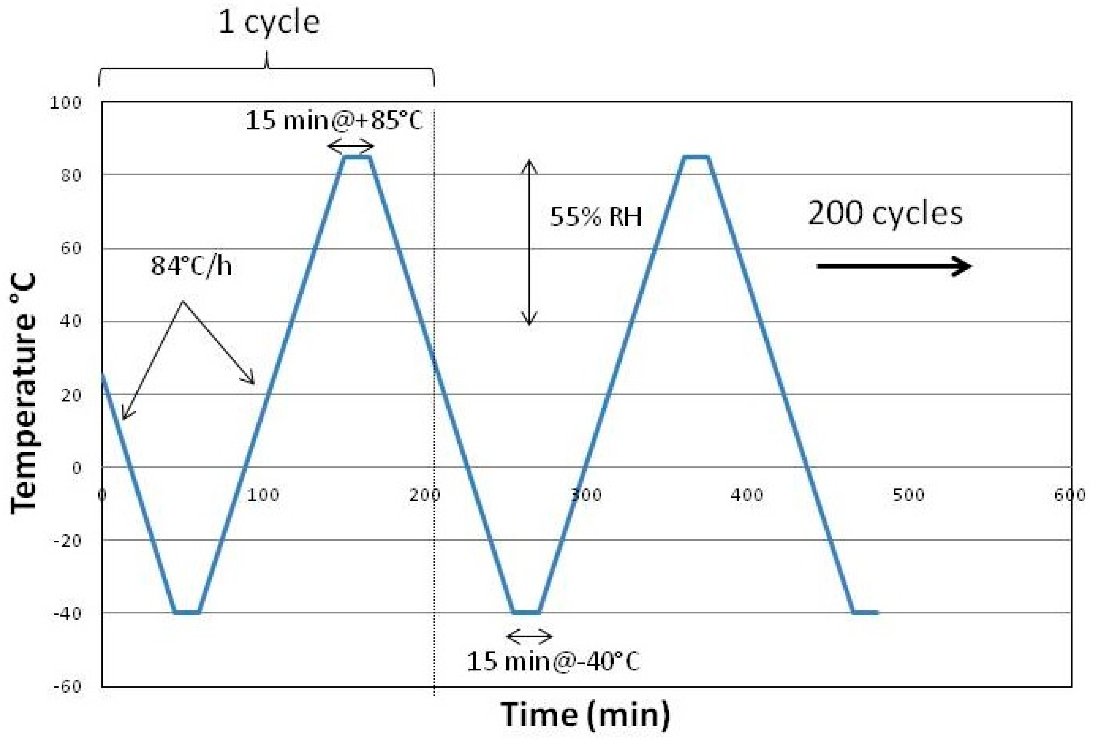
2.5.1. Thermal Cycles

The humidity and temperature tests, designed to examine the relevant polymeric materials (EVA, PMMA, and EVA-PVDF), were carried out following the parameters established by the International Summit on Organic Photovoltaic Stability (ISOS), adhering to the ISOS-T stability criteria concerning perovskite-based devices.
The purpose of the thermal cycling test was to determine the device’s capability to withstand thermal imbalances, fatigue, or other stresses caused by repeated temperature changes. This test is particularly relevant for any photovoltaic technology intended for outdoor use, as it simulates realistic humidity conditions [54]. For PSCs, this test holds special significance in studying degradation processes attributed to ion accumulation at contacts [54,55], analyzing temperature variation instead of applying constant extreme temperatures.
The tests were conducted in a climate chamber (CTC256, manufactured by MEMMERT) in accordance with ISOS-T-3 [54]. Thus, between 6 and 7 thermal cycles were performed daily from −40 °C to 85 °C (see Figure 4) in darkness until the number of cycles reached 200. The relative humidity was maintained at 55% at temperatures above 40 °C, with no set humidity point below this temperature threshold. The temperature changes were made with increments lower than 100 °C per hour, keeping the samples at a constant temperature for at least 10 min at each increment [56].

2.5.2. UV Irradiation

In previous studies, the evaluation of the transmittance of the three polymeric encapsulating materials was conducted. Specifically, it was observed that PMMA allowed light transmission from 300 nm onwards, while the encapsulated samples incorporating an EVA layer effectively blocked irradiation above 400 nm. Therefore, these latter materials were considered more appropriate for preserving the perovskite layers from the UV portion of the spectrum. Additionally, it was found that the encapsulation composed solely of EVA presented higher transmittance compared to the combination of EVA and PVDF. This disparity suggests that perovskite may absorb more light in the former case, possibly resulting in higher efficiency [35,56]. The results were jointly analyzed with the UV lamp spectrum used in the degradation processes, confirming that encapsulants composed of glass and EVA, as well as of glass and EVA plus PVDF, effectively function as UV ray-blocking agents below 400 nm [57]. Furthermore, in previous studies the impact of UV irradiation on the degradation process of perovskite layers has been proved [34], confirming the encapsulation method’s resistance to low temperatures and solar irradiation. To complete these previous analyses, the comparative evaluation of the three polymeric encapsulation materials studied (EVA, PMMA, and EVA-PVDF) was conducted, exposing encapsulated MAPbI3 thin-films materials to a 24 W UV lamp (365–395 nm) positioned orthogonally to the samples. The exposure period was 350 h (with a power of 6051.00 kW/m2). This timeframe allowed for an assessment to determine which polymeric material provides optimal protection for the perovskite layer against ultraviolet irradiation.

3. Experimental Results

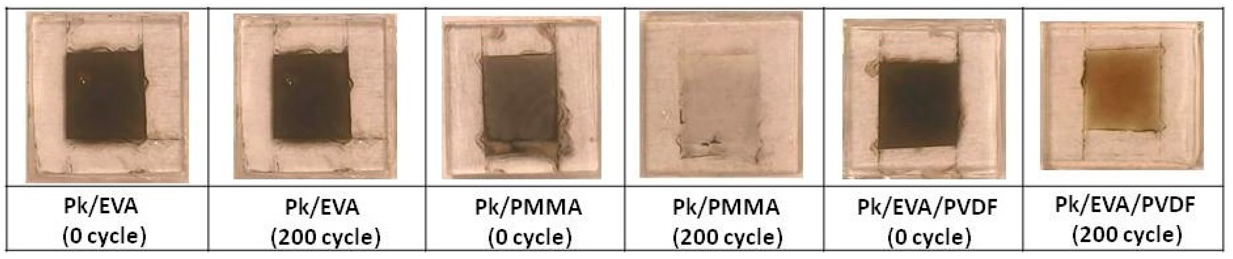
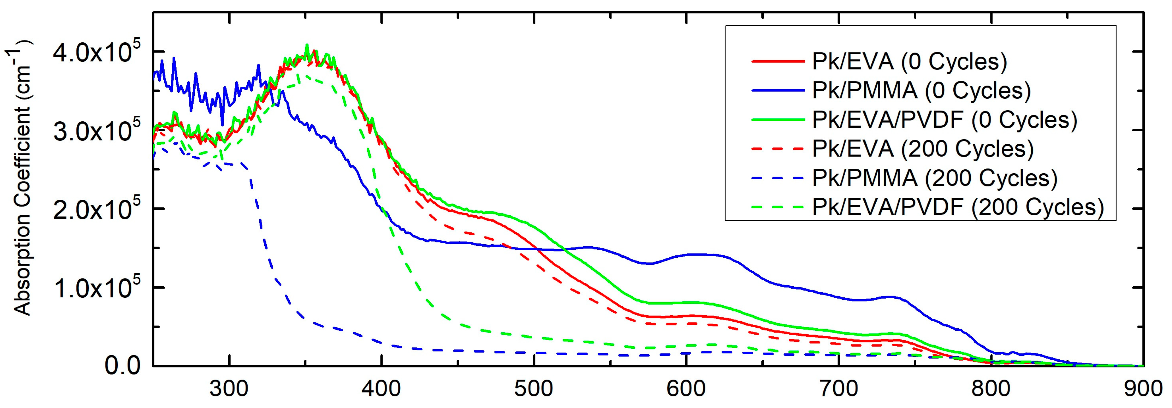
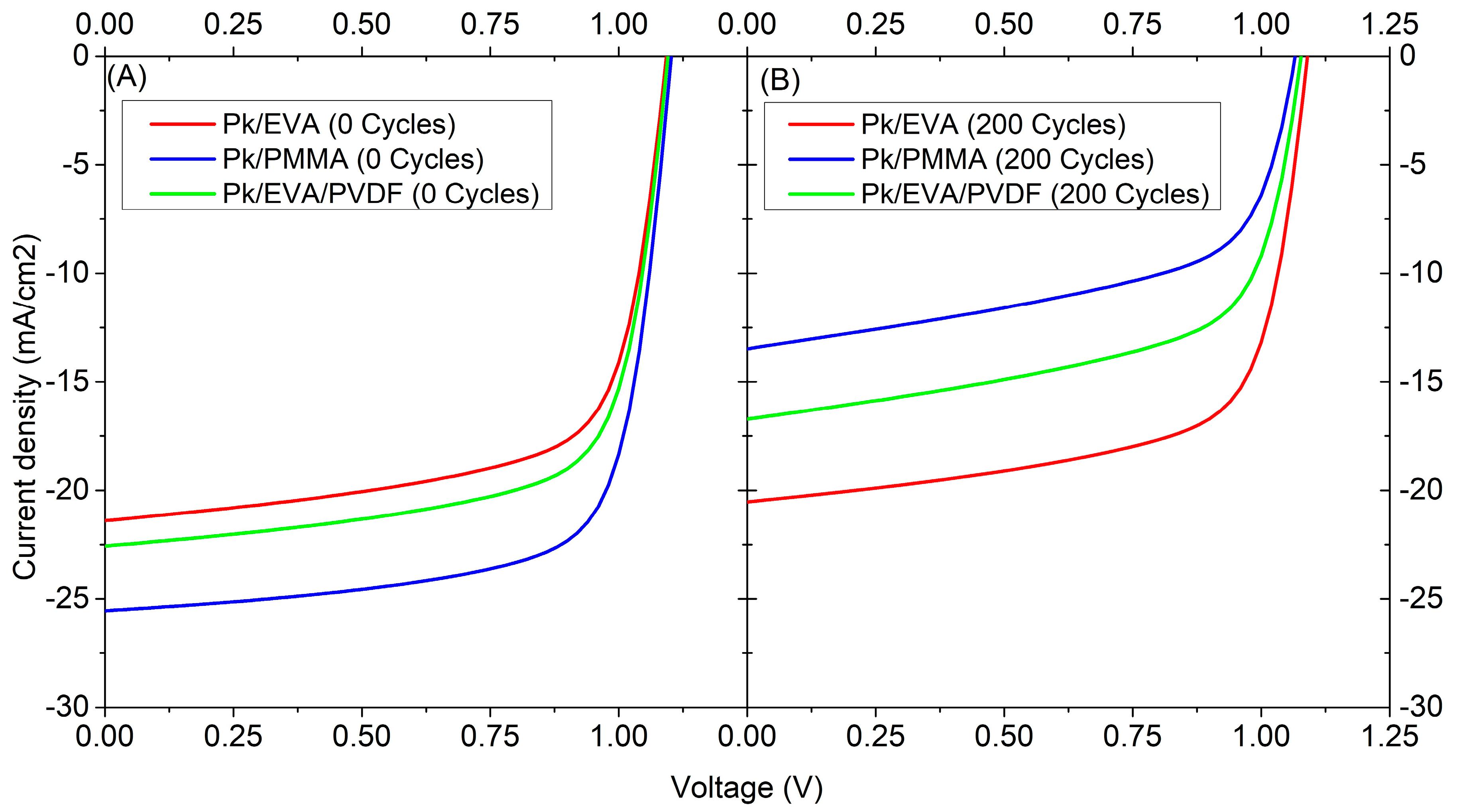
3.1. Test against Humidity and Temperature (ISOS-T)

In this section, a detailed analysis of the results derived from the humidity and temperature test conducted on samples encapsulated with the three studied polymers, EVA, PMMA, and EVA-PVDF, is presented.
Figure 5 displays representative images captured using a digital microscope before and after subjecting the samples to the considered thermal cycling test. From left to right, the first two images depict samples encapsulated with EVA, designated as “Pk/EVA (0 cycle)” and “Pk/EVA (200 cycles)”, images three and four showcase samples encapsulated with PMMA, designated as “Pk/ PMMA (0 cycle)” and “Pk/PMMA (200 cycles)”, and the last two images display samples encapsulated with EVA combined with PVDF, designated as “Pk/EVA/PVDF (0 cycle)” and “Pk/EVA/PVDF (200 cycles)”. As can be seen, after applying 200 thermal cycles, the samples encapsulated with EVA maintained their original appearance without exhibiting macroscopic defects and variations in color, which suggest higher levels of stability throughout the test. In contrast, the perovskite layers encapsulated with the other polymers (PMMA and EVA with PVDF) showed immediate discoloration after the encapsulation process and a significant color change by the end of the thermal cycles. These results indicate that, for the studied polymers, only EVA, is really suitable as an encapsulant against exposure to temperature changes.
Measurements of the absorption coefficient curves were conducted before and after the produced samples were subjected to the thermal cycles by using spectroscopic ellipsometer.
Differences in the absorption coefficient were also calculated to identify the effects of temperature and humidity on the encapsulated samples, depending on the polymer used. As depicted in Figure 6, the samples encapsulated with EVA displayed a moderate reduction in the absorption coefficient curve, reaching a peak at 2.46 × 104 cm−1 within the range of 400 to 760 nm (and thus below the perovskite’s band gap location at 1.6 eV). However, the samples encapsulated with PMMA show a significant degradation over the analyzed spectrum after 200 cycles, fluctuating in particular around 300–400 nm and peaking at 2.51 × 105 cm−1 at 335 nm. Additionally, the samples encapsulated with EVA combined with PVDF showed a lower degradation along the spectrum, with a maximum absorption coefficient of 1.52 × 105 cm−1 at 475 nm. Several researchers suggest that this phenomenon can be associated with the formation of various species of multiplumbate ions, such as PbI5S3−, PbI64−, and (Pb2I4)n [58].
The values obtained in the previous section were used to produce SCAPS-1D simulation, in order to assess their impact on the perovskite layers within fully functional PSC. Thus, Figure 7 compares the IV curves of the samples encapsulated with EVA, PMMA, and EVA combined with PVDF (designated as PSC/EVA, PSC/PMMA, and PSC/EVA/PVDF, respectively) before and after undergoing the thermal cycle test. As expected, the samples encapsulated with EVA consistently maintained constant power conversion efficiencies after the test, experiencing only a 0.9% reduction in their PCE. In contrast, the samples encapsulated with PMMA underwent a significant decrease in PCE, dropping from 20.20% to 8.28%, while the samples encapsulated with EVA + PVDF went from 17.06% to 11.10% (see Table 3). These results indicate that the polymer exhibiting better performance against thermal variations in humid environments was EVA. In all cases, the reduction in device efficiency was due to a significant decrease in current, which can be explained by an increase in the series resistance of the device caused by the deterioration of the MAPbI3 layer, resulting in increased losses between the electrode and the absorptive layer.

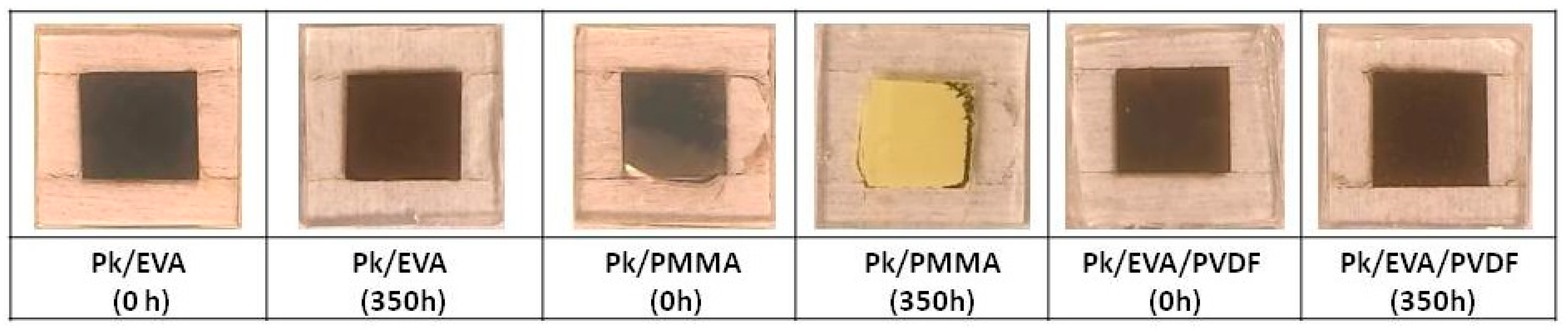
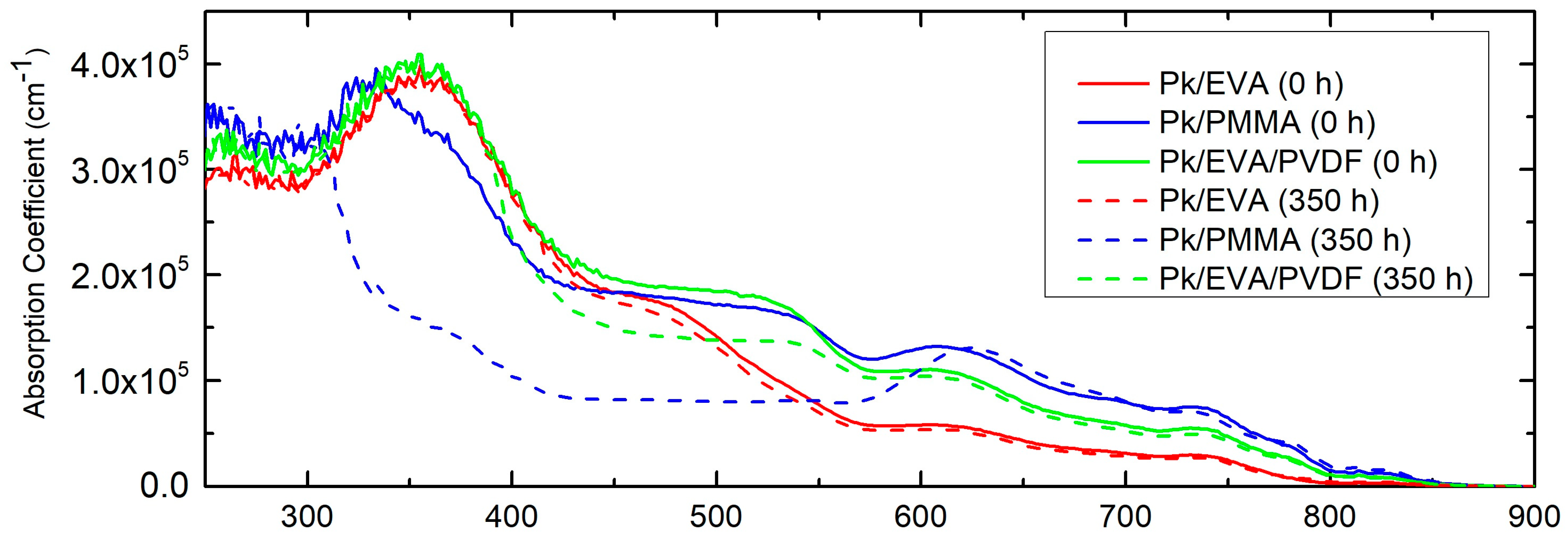
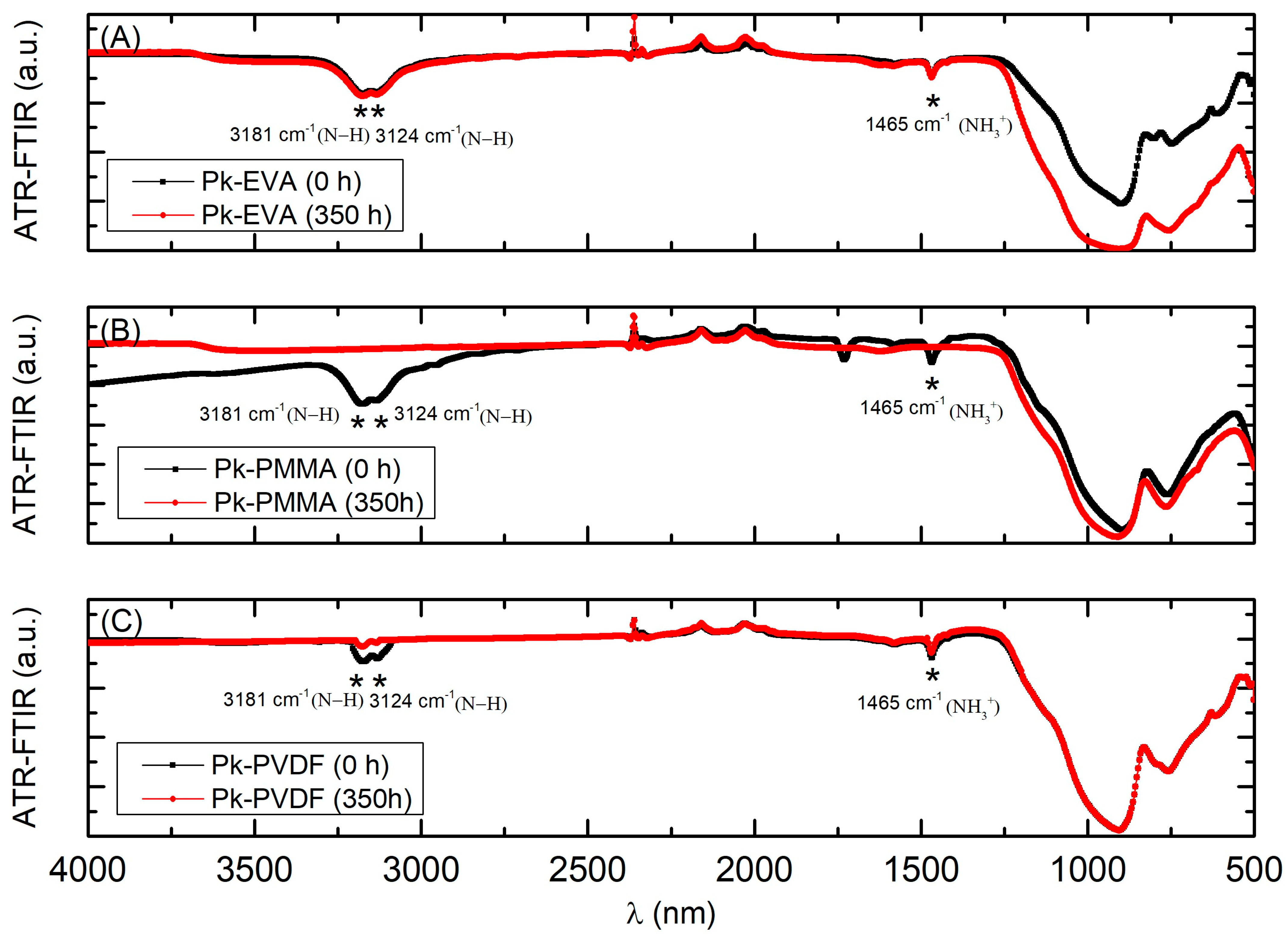
3.2. Test against UV Irradiation

In this section, a detailed analysis of the results from the UV irradiation test conducted on samples encapsulated with the three studied polymers, EVA, PMMA, and EVA-PVDF, is presented.
Figure 8 displays representative optical microscopy images of the samples before and after subjecting the samples to the considered ultraviolet irradiation test. From left to right, the first two images depict samples encapsulated with EVA, designated as “Pk/EVA (0 h)” and “Pk/EVA (350 h)”; images three and four showcase samples encapsulated with PMMA, designated as “Pk/PMMA (0 h)” and “Pk/PMMA (350 h)”; and the last two images display samples encapsulated with EVA combined with PVDF, designated as “Pk/EVA/PVDF (0 h)” and “Pk/EVA/PVDF (350 h)”. Upon close examination, it was evident that after 350 h of exposure to the UV lamp, the samples encapsulated with EVA retained their original appearance without exhibiting discernible macroscopic defects and variations in color. This finding indicates a remarkable level of stability throughout the entire test. It was also noteworthy that samples encapsulated with other polymers, especially PMMA, showed yellowing of the layer. These results were attributed to a degradation mechanism triggered by UV irradiation [37,59]. Meanwhile, those encapsulated with a combination of EVA and PVDF displayed numerous spots on their surfaces. This outcome suggests that the latter two materials may not be suitable for application on perovskite layers and may not offer adequate protection against UV irradiation in environments with moisture presence.
Measurements of the absorption coefficient curves were conducted before and after the produced samples were subjected to the UV irradiation test by using spectroscopic ellipsometer. As shown in Figure 9, the EVA-encapsulated samples showed minimal reduction in the absorption coefficient curve after 350 h, with a maximum deviation at 403 nm, with a difference of 1.31 × 104 cm−1 after the test was carried out. However, the samples encapsulated with PMMA and EVA with PVDF showed greater degradation. In particular, the samples encapsulated with PMMA showed higher degradation in the range of 350 to 400 nm, with a maximum deviation at 333 nm, with an absorption coefficient reduction of 2.08 × 105 cm−1 after the irradiation. In the case of the EVA combined with PVDF, the maximum reduction was found between 400 and 550 nm, with a maximum deviation at 441 nm, with an absorption coefficient reduction of 5.02 × 104 cm−1.
Figure 10 presents the results derived from the FTIR analysis of the samples encapsulated with EVA (A), PMMA (B), and EVA combined with PVDF (C) after undergoing UV irradiation exposure for a period of 350 h, replicating the previously established characterization protocol [35]. As can be seen, the samples encapsulated with an EVA film exhibit a significant protective effect against UV irradiation, compared to the samples encapsulated with the other polymers tested. Thus, the samples encapsulated with EVA do maintain the intensity of characteristic peaks such as the ammonium functional groups throughout the process, located at 3181 cm−1 (N-H, stretch), 3124 cm−1 (N-H, stretch), and 1465 cm−1 (NH3+, symmetric bonding) [60] following the execution of the test. In contrast, the samples encapsulated with PMMA show the characteristic peaks of functional groups at the beginning of encapsulation, which completely disappear after 350 h. For the samples encapsulated with EVA combined with PVDF, the intensity of their characteristic peaks slightly decreased after the exposure time. These findings underscore the efficacy of EVA as a UV protection agent, highlighting its superiority compared to the alternative polymers considered in this study.
The simulation of devices was conducted using SCAPS 1D software, following the characterization methodology defined in Section 2.5.1, and employing data related to the thickness, bandgap, and absorption coefficient curve of the device layers. These data were used to extrapolate the degradation observed in the samples after the UV irradiation test to the SCAPS 1-D software. Figure 11 compares the IV curves of the samples encapsulated with EVA, PMMA, and EVA-PVDF, designated as PSC/EVA, PSC/PMMA, and PSC/EVA/PVDF, respectively, before and after undergoing the UV irradiation test. As depicted in the graph, the samples encapsulated with EVA effectively maintained their power conversion efficiencies after the test, experiencing only 9.58% reduction in their PCE, decreasing from 15.37% to 13.90% of PCE. In notable contrast, the samples encapsulated with PMMA underwent a significant decrease in PCE, dropping from 19.81% to 9.26%. On the other hand, the samples encapsulated with EVA combined with PVDF went from 18.68% to 14.13% (as detailed in Table 4). Additionally, similar to the previous test, in all cases, the devices maintained their open-circuit voltage, while the short-circuit current increased, thereby reducing cell efficiency.

4. Conclusions

In previous studies, a new method was evaluated to shield perovskite solar cells from environmental factors like humidity, oxygen, heat, and UV light. It was confirmed that non-encapsulated MAPbI3 perovskite samples displayed visual and optical degradation after 50 min of exposure to UV light under standard humidity conditions. Furthermore, distinctive functional groups of the perovskite layer were identified through FTIR analysis, serving as indicators marking the degradation of perovskite caused by ultraviolet light. This work has enabled progress in research developed to improve the stability of perovskite-based devices, evaluating the encapsulation method with different polymers, under conditions of humidity, temperature, and UV radiation.
Based on the results of tests following the protocols of the International Summit on Organic Photovoltaic Stability (ISOS-T), the performance of the three polymers considered for encapsulating the perovskite layers, EVA, PMMA, and the combination of EVA with PVDF, as materials for protection against variations in humidity and temperature, could be evaluated. It was determined that encapsulation exclusively using EVA film offered better results compared to encapsulation with PMMA or the combination of EVA with PVDF. This was evident both in terms of protection against humidity and temperature. The EVA encapsulations demonstrated greater efficacy in safeguarding the perovskite layer against significant temperature changes, showing that their absorption coefficient curves decreased by only 2.46 × 104 cm−1 at their maximum peak at 473 nm. Conversely, the absorption coefficient curve values observed for samples encapsulated with the other polymers have their maximum reduction of 2.51 × 105 cm−1 at 335 nm for PMMA and 1.52 × 105 cm−1 at 475 nm for EVA combined with PVDF.
Using this data, along with the bandgap and thickness of the perovskite layers, a simulation was performed to assess the impact of thermal cycling tests on encapsulated perovskite solar devices. It was found that the electrical parameters such as PCE (power conversion efficiency), FF (fill factor), Isc (short-circuit current), and Voc (open-circuit voltage) obtained from the samples encapsulated solely with EVA remained stable after 200 thermal cycles, maintaining an efficiency of 15.06% compared to the initial 15.96%, while those encapsulated with PMMA and EVA-PVDF experienced a greater reduction in their PCE. In the case of PMMA, where the observed degradation was greater, it is suggested that the encapsulation with this polymer was somehow inefficient, since it was more affected by humidity and temperature after the repetition of the thermal cycles; thus, further contributing to the degradation of the MAPbI3 layer. While in the case of EVA combined with PVDF, we suspect this failure may stem from inadequate adhesion of the PVDF layer during the encapsulation process. In this scenario, the EVA sheet does not directly contact the cover glass but interfaces with the PVDF layer, potentially leading to increased fragility due to the greater number of layers, thereby elevating the risk of thermal bridge rupture. Additionally, a comprehensive chemical analysis following degradation has not been conducted to confirm if there has been any decomposition of the PMMA and the PVDF layer that could compromise the device’s integrity. In forthcoming projects, we aim to introduce variations in the encapsulation process by adjusting temperature and pressure.
Furthermore, the behavior of the three polymers studied as encapsulation materials intended to preserve the perovskite layers against harmful effects from ultraviolet irradiation and humidity conditions has been evaluated comprehensively. After the comprehensive execution of the tests, it was evident that the encapsulation strategy based solely on EVA emerged as the most efficient choice. This is in agreement with prior analyses conducted on encapsulation materials, confirming that EVA-encapsulated samples effectively block UV radiation below 400 nm, while PMMA-encapsulated samples enable light transmission starting from 300 nm onward [57]. The EVA option has exhibited significantly superior results compared to PMMA and the combination of EVA with PVDF regarding protection against UV irradiation. Specifically, an encapsulate made only with EVA effectively blocks the irradiation below 400 nm, resulting in a minimal decrease in the absorption coefficient curve, with a marginal reduction of 1.31 × 104 cm−1 at 403 nm compared to the absorption coefficient curve of pristine samples. In contrast, the samples encapsulated with the other polymers experienced substantial reductions in their absorption coefficient, ranging between 2.08 × 105 cm−1 at 333 nm and 5.02 × 104 cm−1 at 441 nm for PMMA and EVA combined with PVDF, respectively. Additionally, these results were confirmed after conducting FTIR analysis, where it was observed that samples encapsulated with EVA maintain the intensity of characteristic peaks of ammonium functional groups located at 3181 cm−1 (N-H, stretch), 3124 cm−1 (N-H, stretch), and 1465 cm−1 (NH3+, symmetric bonding) [60], compared to samples encapsulated with PMMA and EVA combined with PVDF.
Moreover, after simulating encapsulated perovskite solar cells against UV irradiation, the results revealed that the electrical parameters of cells encapsulated in EVA, including energy conversion efficiency, fill factor, short-circuit current, and open-circuit voltage, remained stable after exposure to UV irradiation. In particular, their efficiency remained at 13.90% compared to the initial value of 15.37%.

Author Contributions

Conceptualization, L.O., C.M., S.G.-P. and B.G.-D.; methodology, L.O., C.M., S.G.-P. and B.G.-D.; software, L.O.; validation, L.O., C.M., S.G.-P. and B.G.-D.; formal analysis, L.O., C.M., S.G.-P. and B.G.-D.; investigation, L.O. and C.M.; resources, L.O., C.M., S.G.-P. and B.G.-D.; data curation, L.O.; writing—original draft preparation, L.O.; writing—review and editing, L.O., C.M., S.G.-P. and B.G.-D.; visualization, L.O., C.M., S.G.-P. and B.G.-D.; supervision, Montes, S.G.-P., B.G.-D. and E.L.; project administration, E.L.; funding acquisition, L.O., C.M. and E.L. All authors have read and agreed to the published version of the manuscript.

Funding

This research and the APC has been funded by Interreg (V-A—Spain-Portugal (Madeira-Açores-Canarias—MAC) 2014–2020), Grant number: MAC2/1.1a/395.

Data Availability Statement

The data presented in this study are available on request from the corresponding author. The data are not publicly available due to privacy.

Acknowledgments

This work has been developed within the MACLAB-PV project framework, which has been co-financed by the INTERREG Madeira-Azores-Canarias Territorial Cooperation Programme (MAC) 2014–2020, Second Call. Axis 1—Enhancing research, technological development and innovation.

Conflicts of Interest

The authors declare no conflict of interest.

References

  1. Laboratory National Renewable Energy, (NREL). Best Research-Cell Efficiency Chart. Available online: https://www.nrel.gov/pv/cell-efficiency.html (accessed on 1 November 2023).
  2. Kundu, S.; Kelly, T.L. In Situ Studies of the Degradation Mechanisms of Perovskite Solar Cells. EcoMat 2020, 2, e12025. [Google Scholar] [CrossRef]
  3. Wang, R.; Mujahid, M.; Duan, Y.; Wang, Z.K.; Xue, J.; Yang, Y. A Review of Perovskites Solar Cell Stability. Adv. Funct. Mater. 2019, 29, 1808843. [Google Scholar] [CrossRef]
  4. Duijnstee, E.A.; Gallant, B.M.; Holzhey, P.; Kubicki, D.J.; Collavini, S.; Sturdza, B.K.; Sansom, H.C.; Smith, J.; Gutmann, M.J.; Saha, S.; et al. Understanding the Degradation of Methylenediammonium and Its Role in Phase-Stabilizing Formamidinium Lead Triiodide. J. Am. Chem. Soc. 2023, 145, 10275–10284. [Google Scholar] [CrossRef] [PubMed]
  5. National Renewable Energy Laboratory, (NREL). Champion Photovoltaic Module Efficiency Chart. Available online: https://www.nrel.gov/pv/module-efficiency.html (accessed on 1 November 2023).
  6. Yang, J.; Siempelkamp, B.D.; Liu, D.; Kelly, T.L. Investigation of CH3NH3PbI3 degradation Rates and Mechanisms in Controlled Humidity Environments Using in Situ Techniques. ACS Nano 2015, 9, 1955–1963. [Google Scholar] [CrossRef] [PubMed]
  7. Al Mamun, A.; Mohammed, Y.; Ava, T.T.; Namkoong, G.; Elmustafa, A.A. Influence of Air Degradation on Morphology, Crystal Size and Mechanical Hardness of Perovskite Film. Mater. Lett. 2018, 229, 167–170. [Google Scholar] [CrossRef]
  8. Wang, Q.; Chen, B.; Liu, Y.; Deng, Y.; Bai, Y.; Dong, Q.; Huang, J. Scaling Behavior of Moisture-Induced Grain Degradation in Polycrystalline Hybrid Perovskite Thin Films. Energy Environ. Sci. 2017, 10, 516–522. [Google Scholar] [CrossRef]
  9. Leguy, A.; Hu, Y.; Campoy-Quiles, M.; Isabel Alonso, M.; Weber, O.J.; Azarhoosh, P.; van Schilfgaarde, M.; Weller, M.T.; Bein, T.; Nelson, J.; et al. The Reversible Hydration of CH3NH3PbI3 in Films, Single Crystals and Solar Cells. Chem. Mater. 2015, 27, 3397–3407. [Google Scholar] [CrossRef]
  10. Li, D.; Bretschneider, S.A.; Bergmann, V.W.; Hermes, I.M.; Mars, J.; Klasen, A.; Lu, H.; Tremel, W.; Mezger, M.; Butt, H.-J.; et al. Humidity-Induced Grain Boundaries in MAPbI3 Perovskite Films. J. Phys. Chem. C 2016, 120, 6363–6368. [Google Scholar] [CrossRef]
  11. Fransishyn, K.M.; Kundu, S.; Kelly, T.L. Elucidating the Failure Mechanisms of Perovskite Solar Cells in Humid Environments Using In Situ Grazing-Incidence Wide-Angle X-ray Scattering. ACS Energy Lett. 2018, 3, 2127–2133. [Google Scholar] [CrossRef]
  12. Zhou, Y.; Hu, J.; Wu, Y.; Qing, R.; Zhang, C.; Xu, X.; Jiang, M. Review on Methods for Improving the Thermal and Ambient Stability of Perovskite Solar Cells. J. Photonics Energy 2019, 9, 040901. [Google Scholar] [CrossRef]
  13. Byranvand, M.M.; Kharat, A.N.; Taghavinia, N. Moisture Stability in Nanostructured Perovskite Solar Cells. Mater. Lett. 2019, 237, 356–360. [Google Scholar] [CrossRef]
  14. Nie, W.; Blancon, J.-C.; Neukirch, A.J.; Appavoo, K.; Tsai, H.; Chhowalla, M.; Alam, M.A.; Sfeir, M.Y.; Katan, C.; Even, J.; et al. Light-Activated Photocurrent Degradation and Self-Healing in Perovskite Solar Cells. Nat. Commun. 2016, 7, 11574. [Google Scholar] [CrossRef] [PubMed]
  15. Yoon, S.J.; Draguta, S.; Manser, J.S.; Sharia, O.; Schneider, W.F.; Kuno, M.; Kamat, P. V Tracking Iodide and Bromide Ion Segregation in Mixed Halide Lead Perovskites during Photoirradiation. ACS Energy Lett. 2016, 1, 290–296. [Google Scholar] [CrossRef]
  16. DeQuilettes, D.W.; Zhang, W.; Burlakov, V.M.; Graham, D.J.; Leijtens, T.; Osherov, A.; Bulović, V.; Snaith, H.J.; Ginger, D.S.; Stranks, S.D. Photo-Induced Halide Redistribution in Organic–Inorganic Perovskite Films. Nat. Commun. 2016, 7, 11683. [Google Scholar] [CrossRef] [PubMed]
  17. Hoke, E.T.; Slotcavage, D.J.; Dohner, E.R.; Bowring, A.R.; Karunadasa, H.I.; McGehee, M.D. Reversible Photo-Induced Trap Formation in Mixed-Halide Hybrid Perovskites for Photovoltaics. Chem. Sci. 2015, 6, 613–617. [Google Scholar] [CrossRef]
  18. Abdelmageed, G.; Mackeen, C.; Hellier, K.; Jewell, L.; Seymour, L.; Tingwald, M.; Bridges, F.; Zhang, J.Z.; Carter, S. Effect of Temperature on Light Induced Degradation in Methylammonium Lead Iodide Perovskite Thin Films and Solar Cells. Sol. Energy Mater. Sol. Cells 2018, 174, 566–571. [Google Scholar] [CrossRef]
  19. Chen, B.; Song, J.; Dai, X.; Liu, Y.; Rudd, P.N.; Hong, X.; Huang, J. Synergistic Effect of Elevated Device Temperature and Excess Charge Carriers on the Rapid Light-Induced Degradation of Perovskite Solar Cells. Adv. Mater. 2019, 31, 1902413. [Google Scholar] [CrossRef]
  20. Akbulatov, A.F.; Frolova, L.A.; Griffin, M.P.; Gearba, I.R.; Dolocan, A.; Vanden Bout, D.A.; Tsarev, S.; Katz, E.A.; Shestakov, A.F.; Stevenson, K.J.; et al. Effect of Electron-Transport Material on Light-Induced Degradation of Inverted Planar Junction Perovskite Solar Cells. Adv. Energy Mater. 2017, 7, 1700476. [Google Scholar] [CrossRef]
  21. Yang, J.; Hong, Q.; Yuan, Z.; Xu, R.; Guo, X.; Xiong, S.; Liu, X.; Braun, S.; Li, Y.; Tang, J.; et al. Unraveling Photostability of Mixed Cation Perovskite Films in Extreme Environment. Adv. Opt. Mater. 2018, 6, 1800262. [Google Scholar] [CrossRef]
  22. Xu, R.-P.; Li, Y.-Q.; Jin, T.-Y.; Liu, Y.-Q.; Bao, Q.-Y.; O’Carroll, C.; Tang, J.-X. In Situ Observation of Light Illumination-Induced Degradation in Organometal Mixed-Halide Perovskite Films. ACS Appl. Mater. Interfaces 2018, 10, 6737–6746. [Google Scholar] [CrossRef]
  23. Li, Y.; Xu, X.; Wang, C.; Ecker, B.; Yang, J.; Huang, J.; Gao, Y. Light-Induced Degradation of CH3NH3PbI3 Hybrid Perovskite Thin Film. J. Phys. Chem. C 2017, 121, 3904–3910. [Google Scholar] [CrossRef]
  24. Das, C.; Wussler, M.; Hellmann, T.; Mayer, T.; Jaegermann, W. In Situ XPS Study of the Surface Chemistry of MAPI Solar Cells under Operating Conditions in Vacuum. Phys. Chem. Chem. Phys. 2018, 20, 17180–17187. [Google Scholar] [CrossRef] [PubMed]
  25. Tang, X.; Brandl, M.; May, B.; Levchuk, I.; Hou, Y.; Richter, M.; Chen, H.; Chen, S.; Kahmann, S.; Osvet, A.; et al. Photoinduced Degradation of Methylammonium Lead Triiodide Perovskite Semiconductors. J. Mater. Chem. A 2016, 4, 15896–15903. [Google Scholar] [CrossRef]
  26. Stoumpos, C.C.; Malliakas, C.D.; Kanatzidis, M.G. Semiconducting Tin and Lead Iodide Perovskites with Organic Cations: Phase Transitions, High Mobilities, and Near-Infrared Photoluminescent Properties. Inorg. Chem. 2013, 52, 9019–9038. [Google Scholar] [CrossRef] [PubMed]
  27. Baikie, T.; Fang, Y.; Kadro, J.M.; Schreyer, M.; Wei, F.; Mhaisalkar, S.G.; Graetzel, M.; White, T.J. Synthesis and Crystal Chemistry of the Hybrid Perovskite (CH3NH3)PbI3 for Solid-State Sensitised Solar Cell Applications. J. Mater. Chem. A 2013, 1, 5628–5641. [Google Scholar] [CrossRef]
  28. Conings, B.; Drijkoningen, J.; Gauquelin, N.; Babayigit, A.; D’Haen, J.; D’Olieslaeger, L.; Ethirajan, A.; Verbeeck, J.; Manca, J.; Mosconi, E.; et al. Intrinsic Thermal Instability of Methylammonium Lead Trihalide Perovskite. Adv. Energy Mater. 2015, 5, 1500477. [Google Scholar] [CrossRef]
  29. Kim, N.-K.; Min, Y.H.; Noh, S.; Cho, E.; Jeong, G.; Joo, M.; Ahn, S.-W.; Lee, J.S.; Kim, S.; Ihm, K.; et al. Investigation of Thermally Induced Degradation in CH3NH3PbI3 Perovskite Solar Cells Using In-Situ Synchrotron Radiation Analysis. Sci. Rep. 2017, 7, 4645. [Google Scholar] [CrossRef]
  30. Tan, K.W.; Moore, D.T.; Saliba, M.; Sai, H.; Estroff, L.A.; Hanrath, T.; Snaith, H.J.; Wiesner, U. Thermally Induced Structural Evolution and Performance of Mesoporous Block Copolymer-Directed Alumina Perovskite Solar Cells. ACS Nano 2014, 8, 4730–4739. [Google Scholar] [CrossRef]
  31. Dualeh, A.; Tétreault, N.; Moehl, T.; Gao, P.; Nazeeruddin, M.K.; Grätzel, M. Effect of Annealing Temperature on Film Morphology of Organic–Inorganic Hybrid Pervoskite Solid-State Solar Cells. Adv. Funct. Mater. 2014, 24, 3250–3258. [Google Scholar] [CrossRef]
  32. Chang, C.-Y.; Huang, Y.-C.; Tsao, C.-S.; Su, W.-F. Formation Mechanism and Control of Perovskite Films from Solution to Crystalline Phase Studied by in Situ Synchrotron Scattering. ACS Appl. Mater. Interfaces 2016, 8, 26712–26721. [Google Scholar] [CrossRef]
  33. Eperon, G.E.; Stranks, S.D.; Menelaou, C.; Johnston, M.B.; Herz, L.M.; Snaith, H.J. Formamidinium Lead Trihalide: A Broadly Tunable Perovskite for Efficient Planar Heterojunction Solar Cells. Energy Environ. Sci. 2014, 7, 982–988. [Google Scholar] [CrossRef]
  34. Beal, R.E.; Slotcavage, D.J.; Leijtens, T.; Bowring, A.R.; Belisle, R.A.; Nguyen, W.H.; Burkhard, G.F.; Hoke, E.T.; McGehee, M.D. Cesium Lead Halide Perovskites with Improved Stability for Tandem Solar Cells. J. Phys. Chem. Lett. 2016, 7, 746–751. [Google Scholar] [CrossRef] [PubMed]
  35. Ocaña, L.; Montes, C.; González-Pérez, S.; González-Díaz, B.; Llarena, E. Characterization of a New Low Temperature Encapsulation Method with Ethylene-Vinyl Acetate under UV Irradiation for Perovskite Solar Cells. Appl. Sci. 2022, 12, 5228. [Google Scholar] [CrossRef]
  36. Collavini, S.; Cabrera-Espinoza, A.; Delgado, J.L. Organic Polymers as Additives in Perovskite Solar Cells. Macromolecules 2021, 54, 5451–5463. [Google Scholar] [CrossRef]
  37. Boyd, C.C.; Cheacharoen, R.; Leijtens, T.; McGehee, M.D. Understanding Degradation Mechanisms and Improving Stability of Perovskite Photovoltaics. Chem. Rev. 2019, 119, 3418–3451. [Google Scholar] [CrossRef] [PubMed]
  38. Bush, K.A.; Palmstrom, A.F.; Yu, Z.J.; Boccard, M.; Cheacharoen, R.; Mailoa, J.P.; McMeekin, D.P.; Hoye, R.L.Z.; Bailie, C.D.; Leijtens, T.; et al. 23.6%-Efficient Monolithic Perovskite/Silicon Tandem Solar Cells with Improved Stability. Nat. Energy 2017, 2, 17009. [Google Scholar] [CrossRef]
  39. Chowdhury, M.S.; Shahahmadi, S.A.; Chelvanathan, P.; Tiong, S.K.; Amin, N.; Techato, K.; Nuthammachot, N.; Chowdhury, T.; Suklueng, M. Effect of Deep-Level Defect Density of the Absorber Layer and n/i Interface in Perovskite Solar Cells by SCAPS-1D. Results Phys. 2020, 16, 102839. [Google Scholar] [CrossRef]
  40. Slami, A.; Belkaid, A.B. Numerical Study of Based Perovskite Solar Cells by SCAPS-1D. Int. J. Energy Environ. 2019, 3, 17–21. [Google Scholar]
  41. Mandadapu, U.; Vedanayakam, S.V.; Thyagarajan, K. Simulation and Analysis of Lead Based Perovskite Solar Cell Using I confirSCAPS-1D. Indian J. Sci. Technol. 2017, 10, 65–72. [Google Scholar] [CrossRef]
  42. Lin, L.; Jiang, L.; Li, P.; Fan, B.; Qiu, Y.; Yan, F. Simulation of Optimum Band Structure of HTM-Free Perovskite Solar Cells Based on ZnO Electron Transporting Layer. Mater. Sci. Semicond. Process. 2019, 90, 1–6. [Google Scholar] [CrossRef]
  43. Bansal, S.; Aryal, P. Evaluation of New Materials for Electron and Hole Transport Layers in Perovskite-Based Solar Cells through SCAPS-1D Simulations. In Proceedings of the Conference Record of the IEEE Photovoltaic Specialists Conference, Portland, OR, USA, 5–10 June 2016; Institute of Electrical and Electronics Engineers Inc.: New York, NY, USA; Volume 2016, pp. 747–750. [Google Scholar]
  44. Chakraborty, K.; Choudhury, M.G.; Paul, S. Numerical Study of Cs2TiX6 (X = Br−, I−, F− and Cl−) Based Perovskite Solar Cell Using SCAPS-1D Device Simulation. Sol. Energy 2019, 194, 886–892. [Google Scholar] [CrossRef]
  45. Wang, Z.; Fang, J.; Mi, Y.; Zhu, X.; Ren, H.; Liu, X.; Yan, Y. Enhanced Performance of Perovskite Solar Cells by Ultraviolet-Ozone Treatment of Mesoporous TiO2. Appl. Surf. Sci. 2018, 436, 596–602. [Google Scholar] [CrossRef]
  46. Lo, M.F.; Ng, T.W.; Mo, H.W.; Lee, C.S. Direct Threat of a UV-Ozone Treated Indium-Tin-Oxide Substrate to the Stabilities of Common Organic Semiconductors. Adv. Funct. Mater. 2013, 23, 1718–1723. [Google Scholar] [CrossRef]
  47. Montes, C.; Ocaña, L.; González-Pérez, S.; González-Díaz, B.; Friend, M.; Cendagorta, M. Developing an Agglomerate of Graphite and Black Carbon in an Ethylene-Vinyl Acetate in Toluene Solution for Producing Electrodes for HTM-Free Perovskite Solar Cells. In Proceedings of the 37th European Photovoltaic Solar Energy Conference and Exhibition, Virtual, 7–11 September 2020; pp. 667–672. [Google Scholar]
  48. Montes, C.; Ocaña, L.; De Sousa-Vieira, L.; González-Pérez, S.; González-Díaz, B.; Moreno-Ramírez, J.S.; Hernández-Rodríguez, C.; Friend, M.; Cendagorta, M. Fabrication of Smooth, Mirror-like and Pbi 2-Free Thin Film Perovskite Layers in Ambient Conditions. In Proceedings of the 36th European Photovoltaic Solar Energy Conference and Exhibition, Marseilles, France, 9–13 September 2019; pp. 717–720. [Google Scholar]
  49. Troughton, J.; Hooper, K.; Watson, T.M. Humidity Resistant Fabrication of CH3NH3PbI3 Perovskite Solar Cells and Modules. Nano Energy 2017, 39, 60–68. [Google Scholar] [CrossRef]
  50. Ocaña, L.; Montes, C.; González-Pérez, S.; González-Díaz, B.; Friend, M.; Cendagorta, M. Improvements on the Stability of MAPbI3 Thin Films against UV Radiation by a Low Temperature Encapsulation Method That Uses Commercial Ethylene-Vinyl Acetate Sheets. In Proceedings of the 37th European Photovoltaic Solar Energy Conference and Exhibition, Virtual, 7–11 September 2020; EU PVSEC, Ed.; pp. 659–662. [Google Scholar]
  51. Jayant Dharma, A.P. Simple Method of Measuring the Band Gap Energy Value of TiO2 in the Powder form Using a UV/Vis/NIR Spectrometer; PerkinElmer Inc.: Shelton, CT, USA, 2009. [Google Scholar]
  52. Löper, P.; Moon, S.-J.; de Nicolas, S.; Niesen, B.; Ledinsky, M.; Nicolay, S.; Bailat, J.; Yum, J.-H.; De Wolf, S.; Ballif, C. Organic–Inorganic Halide Perovskite/Crystalline Silicon Four-Terminal Tandem Solar Cells. Phys. Chem. Chem. Phys. 2015, 17, 1619–1629. [Google Scholar] [CrossRef]
  53. Ocaña, L.; Montes, C.; González-Pérez, S.; González-Díaz, B.; Llarena, E. Testing Encapsulated Perovskite Solar Cells in a Climatic Chamber by Following the IEC 61215 and IEC 61646 Standards for the Thermal Cycling Test. In Proceedings of the 38th European Photovoltaic Solar Energy Conference and Exhibition, Virtual, 6–10 September 2021; pp. 406–410. [Google Scholar]
  54. Khenkin, M.V.; Katz, E.A.; Abate, A.; Bardizza, G.; Berry, J.J.; Brabec, C.; Brunetti, F.; Bulović, V.; Burlingame, Q.; Di Carlo, A.; et al. Consensus Statement for Stability Assessment and Reporting for Perovskite Photovoltaics Based on ISOS Procedures. Nat. Energy 2020, 5, 35–49. [Google Scholar] [CrossRef]
  55. Schwenzer, J.A.; Rakocevic, L.; Gehlhaar, R.; Abzieher, T.; Gharibzadeh, S.; Moghadamzadeh, S.; Quintilla, A.; Richards, B.S.; Lemmer, U.; Paetzold, U.W. Temperature Variation-Induced Performance Decline of Perovskite Solar Cells. ACS Appl. Mater. Interfaces 2018, 10, 16390–16399. [Google Scholar] [CrossRef]
  56. Ocaña, L.; Montes, C.; González-Díaz, B.; González-Pérez, S.; Llarena, E. Testing EVA, PMMA and PVDF Encapsulated Perovskite Solar Cells in a Climatic Chamber by Following the International Summit on Organic Photovoltaic Stability (ISOS-T) Protocols. In Proceedings of the 8th World Conference on Photovoltaic Energy Conversion, Milan, Italy, 26–30 September 2022; pp. 291–295. [Google Scholar]
  57. Ocaña, L.; Montes, C.; González-Díaz, B.; González-Pérez, S.; Llarena, E. Testing EVA, PMMA and PVDF under UV Irradiation for a New Low Temperature Encapsulation Method for Perovskite Solar Cells. In Proceedings of the EU PVSEC, Lisbon, Portugal, 18–22 September 2023; pp. 020103–001–020103-005. [Google Scholar]
  58. Aranda, C.; Cristobal, C.; Shooshtari, L.; Li, C.; Huettner, S.; Guerrero, A. Formation Criteria of High Efficiency Perovskite Solar Cells under Ambient Conditions. Sustain. Energy Fuels 2017, 1, 540–547. [Google Scholar] [CrossRef]
  59. Seethamraju, S.; Ramamurthy, P.C.; Madras, G. Ionomer Based Blend as Water Vapor Barrier Material for Organic Device Encapsulation. ACS Appl. Mater. Interfaces 2013, 5, 4409–4416. [Google Scholar] [CrossRef]
  60. Szostak, R.; Silva, J.C.; Turren-Cruz, S.-H.; Soares, M.M.; Freitas, R.O.; Hagfeldt, A.; Tolentino, H.C.N.; Nogueira, A.F. Nanoscale Mapping of Chemical Composition in Organic-Inorganic Hybrid Perovskite Films. Sci. Adv. 2019, 5, eaaw6619. [Google Scholar] [CrossRef]
Figure 1. Low temperature encapsulation process.
Energies 17 00060 g001
Figure 2. Temperature during encapsulation curing.
Energies 17 00060 g002
Figure 3. Conceptual architecture of the simulate PSC.
Energies 17 00060 g003
Figure 4. Temperature during the ISOS-T-3 thermal cycling test.
Energies 17 00060 g004
Figure 5. Images of the samples composed of EVA, PMMA and EVA-PVDF, before and after the thermal cycle test.
Energies 17 00060 g005
Figure 6. Absorption coefficient of Pk/EVA, Pk/PMMA, and Pk/EVA/PVDF before and after the thermal cycling test.
Energies 17 00060 g006
Figure 7. Simulation of the IV curves from the SCAPS-1D software, for the Pk/EVA, Pk/PMMA, and Pk/EVA/PVDF samples before (A) and after the thermal cycling test (B).
Energies 17 00060 g007
Figure 8. Images of the samples composed of EVA, PMMA, and EVA-PVDF, before and after the UV irradiation test.
Energies 17 00060 g008
Figure 9. Absorption coefficient of Pk/EVA, Pk/PMMA, and Pk/EVA/PVDF before and after the UV irradiation test.
Energies 17 00060 g009
Figure 10. FTIR of Pk/EVA (A), Pk/PMMA (B), and Pk/EVA/PVDF (C) before and after UV irradiation test.
Energies 17 00060 g010
Figure 11. Simulation of the IV curves from the SCAPS-1D software of the Pk/EVA, Pk/PMMA, and Pk/EVA/PVDF samples before (A) and after the UV irradiation test (B).
Energies 17 00060 g011
Table 1. Synthesis of the perovskite layer (CH3NH3PbI3).
PhaseReagentQuantityUnitPurity
IPbI20.7434g99.00%
DMF1.148µL99.80%
DMSO127.6µL99.90%
IIMAI0.2598g98.00%
Table 2. Characterization tests by sample type.
IDDescriptionCharacterization
Pk/EVAGlass-MAPbI3-EVA-GlassDigital microscope, spectroscopic ellipsometry (absorption coefficient), FTIR
Pk/PMMAGlass-MAPbI3-PMMA-Glass
Pk/EVA/PVDFGlass- MAPbI3-PVDF-Glass
PSC/EVAGlass-PSC-EVA-GlassSimulation (Voc, Isc, Vmax, Imax, FF, η)
PSC/PMMAGlass-PSC-PMMA-Glass
PSC/EVA/PVDFGlass-PSC-PVDF-Glass
Table 3. Simulation results: PSC/EVA, PSC/PMMA, and PSC/EVA/PVDF samples, before and after thermal cycling test.
IDPSC/EVAPSC/PMMAPSC/EVA/PVDF
0 Cycle200 CyclesReduction0 Cycle200 CyclesReduction0 Cycle200 CyclesReduction
Voc (V)1.091.090.22%1.101.073.26%1.101.081.63%
Isc (mA/cm2)21.4020.544.03%25.5513.4947.21%22.5816.7225.93%
FF (%)68.2467.251.45%71.7357.5819.72%69.3461.5811.19%
PCE (%)15.9615.065.63%20.208.2859.00%17.1611.1035.29%
Vmp (V)0.920.910.29%0.930.884.76%0.920.902.45%
Imp (mA/cm2)17.4216.485.35%21.829.3956.95%18.6512.3733.67%
Table 4. Simulation results: PSC/EVA, PSC/PMMA, and PSC/EVA/PVDF samples, before and after UV irradiation test.
IDPSC/EVAPSC/PMMAPSC/EVA/PVDF
0 h350 hReduction0 h350 hReduction0 h350 hReduction
Voc (V)1.091.10−0.63%1.101.100.29%1.101.100.08%
Isc (mA/cm2)20.7618.988.57%25.1112.3051.00%24.0318.4623.15%
FF (%)67.8266.661.72%71.6168.564.26%70.7269.691.47%
PCE (%)15.3713.909.58%19.819.2653.22%18.6814.1324.34%
Vmp (V)0.920.92−0.53%0.930.920.76%0.920.920.36%
Imp (mA/cm2)16.7915.1110.05%21.4020.185.73%20.2315.3624.07%
Disclaimer/Publisher’s Note: The statements, opinions and data contained in all publications are solely those of the individual author(s) and contributor(s) and not of MDPI and/or the editor(s). MDPI and/or the editor(s) disclaim responsibility for any injury to people or property resulting from any ideas, methods, instructions or products referred to in the content.

