Based on the results of the analyses, it was found that during emergency braking from a higher driving speed, the maximum permissible decelerations affecting a person in the transport unit (operator or passengers) may be exceeded. Maximum permissible forces acting on each suspension of the route may also be exceeded. Therefore, concepts of the solutions to increasing the level of safety and comfort of using this means of transport have been suggested. The proposed concepts of changes were implemented in the computational model of the suspended monorail and numerical simulations enabled assessing how the proposed solutions affect dynamic quantities, including the ergonomic assessment of the proposed design solutions.
4.1. Analysis of the Method for Stabilization of the Fast Monorail Route
To be able to travel at a higher speed, the suspended monorail requires proper installation and stabilization of the route. To assess the impact of the superstructure on the dynamic parameters of the suspended monorail, emergency braking was simulated for the speed of 5 ms
−1 with 7 different variants of suspension and stabilization of the monorail route (see
Section 2.4. Expansion of the computational model). Each simulation had the following procedure: acceleration of the transport unit to the speed of 5 ms
−1, travelling at this speed for 1 s, and then emergency braking with two pairs of brake shoes. During the simulation, the time process of acceleration of the transport unit, forces in the route suspensions, and displacements of the rails of the route were recorded.
Figure 12 presents the maximum and minimum accelerations for each variant.
Maximum resultant forces recorded in the selected suspensions of the route (marked as cz11—cz22) are given in
Table 6. The symbols cz11—cz22 correspond to lashings next to each other in each of the seven variants.
The presented results were divided into the following groups in relation to the criterion of the permissible load to the suspensions and arches of the roadway roof support:
Group I: The resultant forces in the suspensions do not exceed 10 kN. The group of these suspensions in the table is marked in green. This means that they are at a low level (safe values).
Group II: The resultant forces in suspensions are greater than 10 kN, but less than 30 kN. This group is marked in yellow and orange in the table. Loads at this level are higher than in group I. However, they do not exceed the permissible values and should not cause dangerous situations.
Group III: The resultant forces in suspensions exceed 30 kN. This group is marked in red in the table. These are the most loaded suspensions. In this group, suspensions should be monitored as limit values may be exceeded. This may result in dangerous situations.
Displacement of the rails (first and tenth rail) was another recorded parameter.
Table 7 presents the maximum displacements in the Y axis (in the direction of travel) and in the Z axis (vertical axis), in relation to the analysed variants of the route suspension method. The results are presented for rails 1 and 10, which in the selected variants were additionally protected by stabilizing lashings. Schemes with descriptions of the suspended route for each variant are presented in [
30].
The largest displacements occurred in relation to the route installed according to variant 1 (without stabilization). Maximum values indicate route destabilization, which in practical terms would not be acceptable. Adding one yielding lashing results in a decrease by approximately 50% and adding two or more by approximately 60%. While emergency braking, displacements of about 180 mm decrease the maximum force in the stabilizing lashings without harming the crew or passengers.
Unfavourable phenomena include excessive movement of the route, observed in variant 1. Stiffening of the route is unfavourable because it results the occurrence of high forces in the lashings of the route (variants 6 and 7) and creates excessive force in a load on the roadway support frame that is more than what is permitted. The presented method of analysis enables the optimization of the method of suspending the monorail route in terms of minimizing the loads to the suspensions and the route stabilization. Numerical simulations should be a permanent practice in the designing process, in particular with regard to sections of routes intended for high-speed suspended railways used for the people movement.
On the basis of the analysis results, it was found that the proper suspension method and stabilization of the suspended monorail route is of key importance in the aspect of safe passenger transport by suspended monorail with the travel speed increased to 5 ms−1. Insufficient stabilization of the route results in its excessive displacement. This phenomenon is unfavourable and can cause dangerous situations, such as breaking the suspension chain or collision of subassemblies of the monorail set with the rest of the mine infrastructure. Excessive displacement of the route was observed during braking in variant 1.
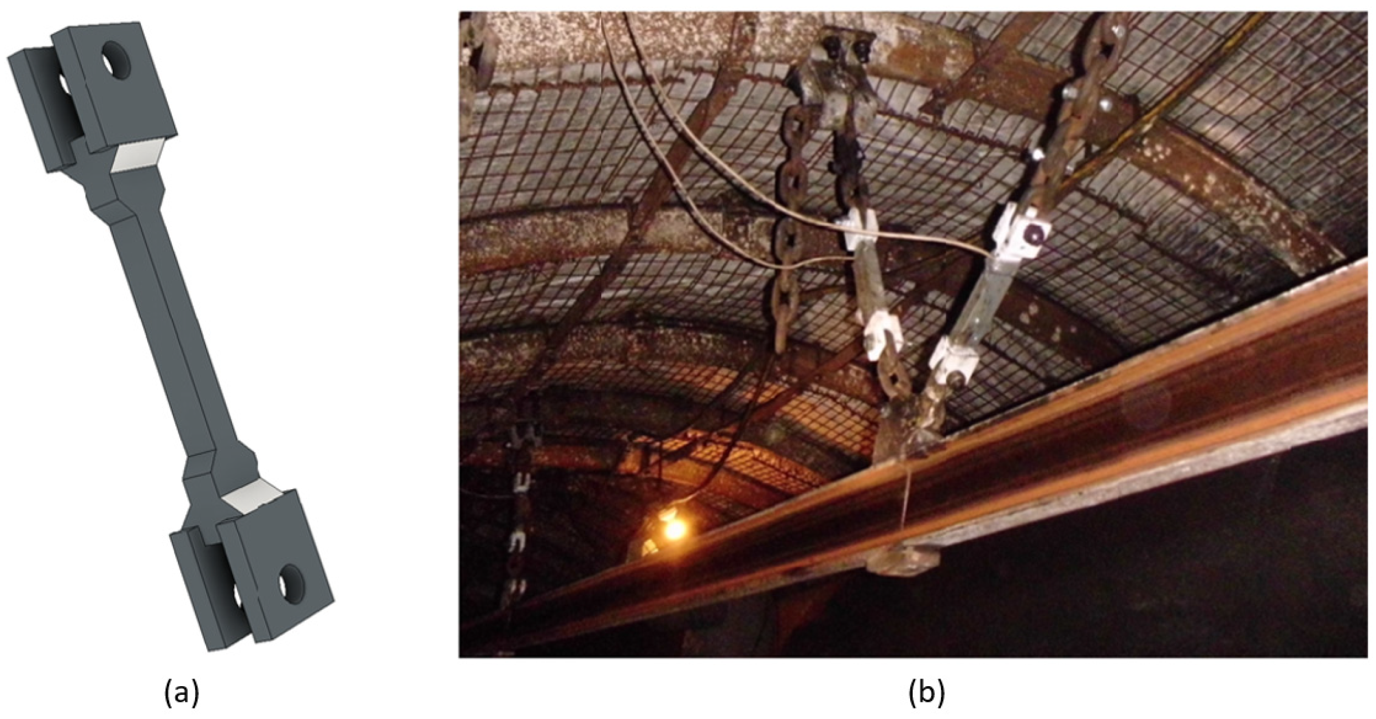
In order to stabilize the route movement, especially in the axis in line with the direction of the monorail travel, it is important to introduce side stabilizing lashings. However, making them more flexible is an effective way to reduce the maximum forces acting on these lashings during the emergency braking. Such a situation is observed in variants 2 and 3, especially with regard to the force component in the direction of the monorail travel.
As a result of the analysis of variants of the suspended monorail route, it was found that:
due to the criterion of minimizing the overloads affecting the operator and the crew, it is most advantageous to use variants 3 and 7;
due to the criterion of minimizing the forces in suspensions of the monorail route, it is most advantageous to use variant 3 or;
due to the criterion of minimizing the forces in the side stabilizing lashings it is best to use variant 4 or 5.
Thus, according to the analyses, each case of designing the route and the method of its suspension and stabilization should be considered individually, taking into account, among others, such data as: the condition of the roadway support at the route construction place, the configuration of the most frequently used transportation unit on a given route, and the type of transport system and the expected frequency of crew movement at increased speed. In the process of designing and analysing the method of suspension and stabilization, the use of numerical simulation techniques can be an effective tool supporting the designers.
4.2. Sequential Emergency Braking Concept and Braking Algorithm
According to Polish law, the suspended monorail assembly must be secured with brake trolleys or other emergency braking devices with a static braking reliability factor of at least 1.5 in relation to the maximum rolling force of the transport set [
31]. In accordance with Polish law, proprietary drives of suspended monorails, intended for use in inclined workings with an inclination of not more than 45°, must have a braking reliability factor, determined as the ratio of the maximum braking force to the maximum traction force of the own drive, not less than 1.5, requiring the braking deceleration of the transport set to be not less than 1 ms
−2 and not more than 10 ms
−2 [
8]. These requirements ensure that a fully loaded transport unit can be effectively stopped at the maximum inclination at which such a transport unit can move. However, in a situation where the transport unit, after unloading, will return unloaded, additionally driving along a horizontal route or on an incline with the maximum permissible speed, it is very likely that the maximum permissible deceleration affecting the monorail operator, i.e., 10 ms
−2, will be exceeded. This is a dangerous situation that could lead to an accident. Considering this problem, KOMAG developed the concept of an innovative, sequential method of braking the suspended monorail, in which the maximum braking force securing the transport unit is maintained. However, it is divided into two braking devices (or, with higher forces, two groups of devices), e.g., a friction brake and a multi-plate brake. In emergency braking, the first braking stage is activated, e.g., a friction brake. Then, the monorail deceleration is monitored and, depending on its value, a decision is made to activate or not activate the second stage of braking. This sequential braking enables adapting the braking force to the current conditions in which the monorail operates (route inclination, mass of the unit and load, etc.). In order to properly control the sequential braking system, a dedicated algorithm has been developed. In this algorithm, the following parameters are set: the limit braking deceleration, which determines the activation of the second stage of braking, and the time of activation of the second stage of the braking system. The block diagram of the sequential emergency braking algorithm (area surrounded by a green line) together with the part responsible for controlling the numerical simulation (area surrounded by a red line) is shown in
Figure 13.
A detailed description of the operation of the sequential braking algorithm is presented in [
32]. A number of numerical simulations were carried out covering the emergency braking process from speeds of 3 ms
−1 and 5 ms
−1, on a horizontal route and on a dip with inclination of 30°, using three different settings of the second stage activation threshold and three values of the second stage activation time delay. In addition, the reduction of the first stage braking force was also taken into account in the simulations. The parameters settings and simulation results of emergency braking from the speed of 3 ms
−1 on a horizontal route are presented in
Table 8.
Parameters settings and simulation results of emergency braking from the speed of 5 ms
−1, on a route without inclination, with different settings of the braking algorithm, is presented in
Table 9.
Parameter settings and simulation results of emergency braking from the speed of 3 ms
−1, on a route to the dip on inclination 30°, with different settings of the braking algorithm, are presented in
Table 10.
Parameter settings and simulation results of emergency braking from the speed of 5 ms
−1, on a route to the dip on inclination 30°, with different settings of the braking algorithm, are presented in
Table 11.
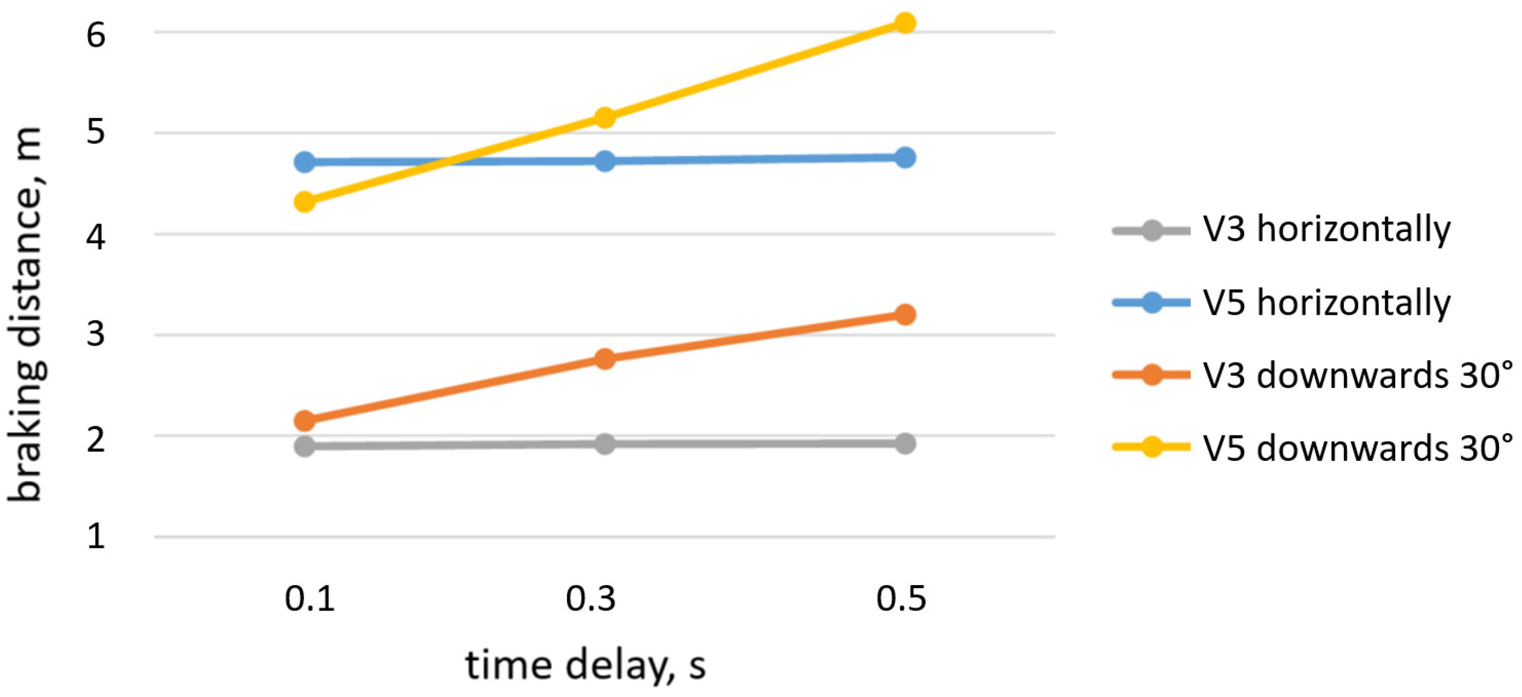
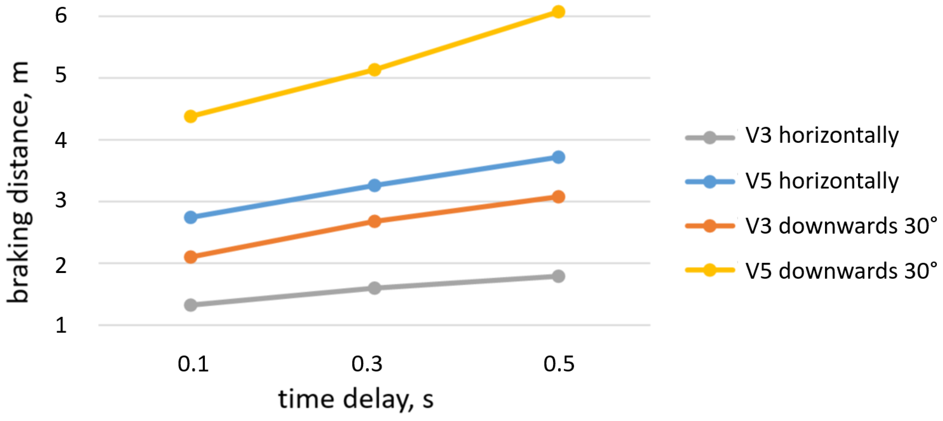
Figure 14,
Figure 15 and
Figure 16 display the braking distance at various first stage braking threshold values, the delay in the second stage braking activation, the speed at which the transportation set was stopped, and the route inclination angles.
In subsequent simulations, the first-stage braking force was reduced from 12,500 N, by 50% (to 6250 N) and by 75% (to 3125 N). The second stage of braking was activated with a time delay of 0.5 s. In addition, with regard to the reduced braking force (by 50% and 25%), simulations were carried out with a second-stage activation time delay of 1 s. All tests were carried out with braking from the speed of 5 ms
−1.
Table 12 presents results of the simulation.
Figure 17 illustrates the dependence of the braking distance, the braking force in the first stage, and the time delay of activation of the second stage of braking.
Figure 18 illustrates the dependence of the maximum deceleration, the braking force in the first stage, and the time delay of activation of the second stage of braking.
The concept of the algorithm is an attempt to increase the safety of users of mine suspended transport. It is aimed at minimizing the dynamic overloads affecting people in the transport set. The action of these overloads may result in uncontrollable changes in the miner’s body’s posture and movement within the cabin, which could cause injury.
Based on the numerical simulations, it can be assumed that, for the studied suspended monorail system, setting the delay time in the range of 0.3–0.5 s and the deceleration threshold at the level of 4 ms−2 will enable the proper braking process during an emergency stop. Emergency braking in different conditions, such as braking on a horizontal and inclined (30°) routes, may result in introducing additional parameters into the algorithm, e.g., information about the current position of the drivetrain (articulation from the vertical position).
4.3. Making the Suspensions of the Operator’s and Passenger’s Cabins More Flexible
Another aspect that has a large impact on the comfort and safety of the crew transported by suspended monorails are vibrations in the operator’s cabins and passengers’ cabins while traveling. Passage through rail connections, imperfections in the route installation, as well as movement of the route during operation are the sources of vibrations. Rollers of suspended monorail, made of steel and moving on a steel rail, contribute significantly in generating the vibrations. Even slight irregularities (e.g., rail joints) or dirt on the rail can be a source of vibrations that are transferred to the machine and operator. The level of vibrations is important when taking into account time of exposure to vibration (train travel time), as well as the aspect of increasing the permissible speed (change of frequency and amplitude of vibrations). As part of the research work of the KOMAG Institute, a new type of yielding suspension of the passenger cabin and use of the inserts damping the vibrations in the operator’s cabin were developed together with the monorail manufacturer. In addition, different types of elastic inserts made of different materials of different stiffness were tested. On this basis, the most suitable material that best reduced the transmission of vibrations from the chassis to the monorail operator available on the market was selected [
33,
34]. In order to analyse the effectiveness of such a solution, numerical simulations were carried out consisting in the passage of a suspended monorail set through a horizontal section of the route. During the simulation, the train set accelerated from 0 s to 0.2 s to the speed of 3.5 ms
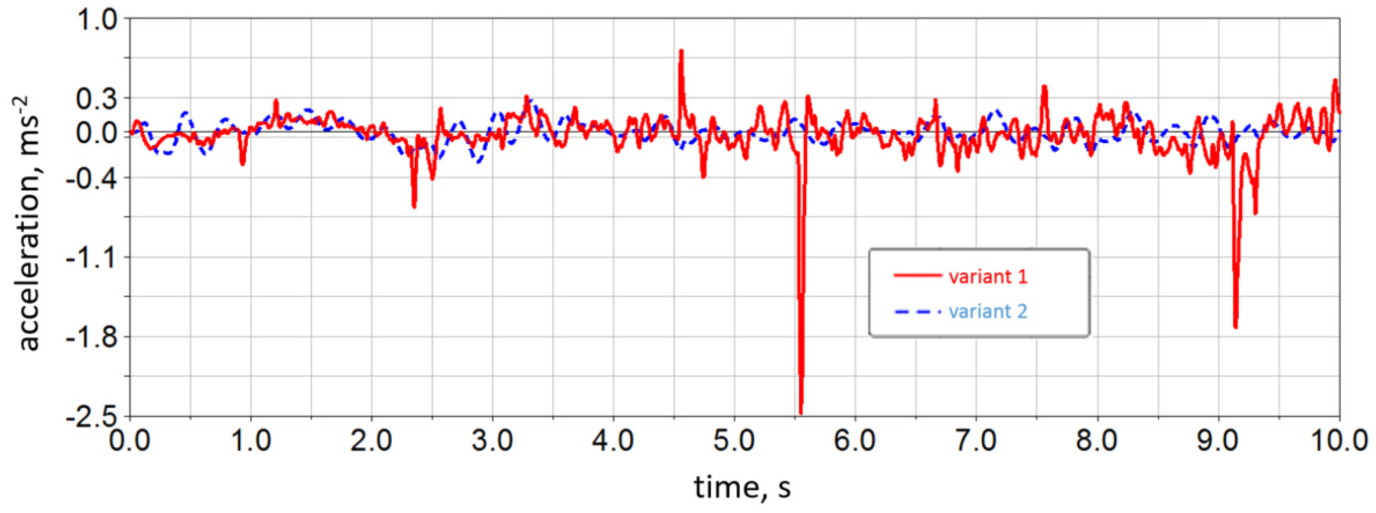
−1. Then, the set moved at a constant speed. While simulating, accelerations acting in cabins in three directions in accordance with the Cartesian coordinate system (X axis perpendicular to the direction of travel of the cable car, axis Y—consistent with the direction of travel of the cable car, axis Z—vertical axis) were recorded. A comparison of accelerations acting in the passenger cabin in the case of a monorail travel with not cushioned cab suspension (variant 1) and yielding suspension (variant 2) is shown in
Figure 19,
Figure 20 and
Figure 21.
Root mean square (RMS) accelerations of the operator’s cabin and the passenger cabin in three directions (X-axis, Y-axis, Z-axis) is another result of the simulations. The RMS values are presented for the simulation of entire passage and for the passage of the monorail at a constant speed, excluding the acceleration phase (2 s–10 s). These results are presented in
Table 13.
Then, in accordance with the provisions of the standard (PN-EN 14253+A1:2011), the daily exposure to vibration was calculated (A(8)). The calculations were performed on the assumption of an 8-h workday, during which the suspended monorail operator was exposed to cabin vibrations for 4 h, while passenger exposure time was supposed to be 2 h, as shown in
Table 14.
Based on an analysis of the results, it can be stated that the solutions introduced to increase the flexibility of the suspension of the operator’s cabin and the passenger cabin have a positive impact on the intensity of vibrations felt by the crew. This means that the vibrations are reduced, increasing the safety and comfort of suspended monorail users in underground mines.
4.5. Introduction of Seat Belts to the Operator Cabin
To improve the safety of the operator in the cabin in a dangerous situation, such as emergency braking or collision of the transport unit with a stationary obstacle, numerical simulations were carried out using the ATB model of anthropometric features. To conduct this part of numerical analysis the Patran (pre- and post-processor) and Dytran (explicit solver) software were used.
In the next stages of the work, it was suggested to equip the operator’s cabin with seat belts. For this purpose, a comparative simulation was carried out along with the determination of the HIC (Head Injury Criterion) coefficient when the cabin hit an obstacle at the speed of 5 ms
−1, when the operator has a seat belt and without one. The visualization of the simulation results is shown in
Figure 23.
A graph of HIC value determined in both versions of the simulation is presented in
Figure 24.
The operator’s cabin should have additional passive safety features, such as seat belts or headrests, according to simulations conducted using the virtual Hybird III dummy and results analysis. In an emergency, these components will shield the operator from severe or even fatal injuries. Suggested additional equipment in the operator’s cabin significantly decreases the HIC value, which should be considered to be minimizing the possibility of severe head injuries.

 ,
, 


