1. Introduction
Drastic climate change caused by global warming has emerged as a major environmental issue. The maritime sector, in the foreseeable future, will have to meet the International Maritime Organization (IMO) 2050 greenhouse gas reduction targets. Although there are several emission-reducing technologies on the market, these are not able to reduce carbon dioxide (CO
2) emissions by large amounts. Moreover, it is expected that the importance of fossil fuels as a major energy source will remain in the near future. In fact, some existing technical measures, such as the use of alternative fuels with zero or reduced carbon content, are still on a fairly low Technology Readiness Level (TRL) and are not expected to be cost-competitive and widely available over the next few decades [
1]. In this context, the global use of fossil fuels and the relatively slow development of renewable energy means that the amount of gas emitted into the atmosphere will continue to rise. In particular, the oxidation of fossil fuels generates billions of tons of anthropogenic emissions of CO
2 [
2,
3,
4].
Thanks to the introduction by the IMO of the Energy Efficiency Design Index (EEDI) and the Ship Energy Efficiency Management Plan (SEEMP), emissions have decreased from 2008 levels; however, even the recent introduction of the Energy Efficiency Existing Index (EEXI) and the Carbon Intensity Indicator (CII) as measures for existing ships will not be sufficient to reach IMO’s goals, targeted at reducing the total greenhouse gas (GHG) emissions from the maritime sector by at least 50% by 2050. In particular, the reduction of CO
2 should reach 85% in 2050, relative to the levels of 2008 [
5,
6].
The desire to achieve a net-zero navigation has driven researchers to find more technologies that are as low-risk as possible, and the solutions based on carbon capture and storage (CCS) play an important role in this regard. This technology has the crucial potential to quickly mitigate greenhouse gases emissions when fossil fuels are used for power generation and has been acquiring great attention due to its possible role in achieving global carbon neutrality [
7,
8,
9,
10,
11,
12]. Indeed, it is widely acknowledged by experts in the field that while advancements in emission-reducing technologies and alternative fuels are important steps towards decreasing carbon emissions, CCS technologies will also be crucial in achieving a substantial reduction of CO
2 levels when other options such as fuel switching are impracticable [
13,
14]. Therefore, CCS technology seems to be a promising and feasible method for reducing the CO
2 emissions of ships, and initial studies indicate that it also has economic feasibility, although the development of effective onboard CCS remains to be achieved [
10,
15,
16].
The working principles of CCS technologies are based on the capture of the CO
2 generated during industrial processes, such as power generation and manufacturing. The captured CO
2 is then transported, usually by pipeline, to a geological storage site, where it is permanently sequestered or stored. Common sites include deep underground saline aquifers, depleted oil and gas reservoirs, or deep, unamendable coal seams. This helps to prevent the CO
2 from re-entering the atmosphere and contributing to climate change [
2,
3,
6].
Nowadays, carbon capture is a proven technology for onshore power plants and other industries. The core objective of the present research is to study the possibility of applying it in the most efficient way in the maritime sector, and specifically, on board vessels to help them to comply with the in-force regulations. Early studies available in literature that discuss CCS technologies suggest that such technologies may present a viable and economically attractive solution to reduce direct emissions from the cargo shipping industry [
17]. However, it is important to note that the studies available in literature that provide technical and economic results based on a particular CCS system also consider a specific type of ship as a case study. Indeed, the importance of performing analyses of CCS integrated with the ship infrastructure, taking into consideration the type and size of the vessel, has been deemed to be fundamental [
6]. For instance, one study conducted on LNG ships has shown that the cost of CO
2 capture is lowest for larger LNG ships, but it emphasized the need for further development and studies [
18]. Another study has led to varying CAPEX for CO
2 capture, depending on the type of ship considered [
19].
The introduction of new technologies on ships implies dealing with a peculiar and fundamental issue, i.e., minimizing the reduction of the cargo space available. Indeed, while this problem does not arise for industrial sites that are built around the chosen technology, on ships, the available space is limited and the size of the various solutions becomes key, affecting the selection of one system over another. This aspect is even more important when pursuing the objective of refitting old ships in order to limit their emissions; in fact, in these cases, the installation of new technologies has to deal with systems and devices already set up on board, and it is not always possible to make major arrangement changes [
20]. Moreover, fostering the application of such technologies in the maritime sector implies the necessity to address other challenges, such as the inadequacy of geological storage capacity and the need to advance the TRL of many technologies that currently are only at a theoretical development level [
6,
21].
Despite the above-mentioned limitations and challenges, advancements of carbon capture technologies for shipping applications are essential to significantly reduce the CO
2 emissions of the maritime sector; their adoption by shipowners will therefore play a key role in achieving short- and long-term objectives [
2,
14]. Furthermore, several regulations that imply financial penalties based on the quantity of atmospheric pollutants released are soon to be introduced; examples are the FuelEU regulation, that is expected to enter into force from 2025, and the EU Emissions Trading System (EU ETS), that will be gradually implemented between 2023 and 2026 [
22]. In addition, the trend toward stricter thresholds could also extend to more types of ships and other countries [
23]. In light of such initiatives that aim to establish a global emission pricing mechanism, carbon capture technology could be a promising solution in the maritime industry.
In this article, the authors aim to research the technologies of carbon capture which are currently available and in use in other industrial sectors and focus on the ones that may be more adoptable for use on board ships due to their technical features. In particular, systems that use Molten Carbonate Fuel Cells (MCFCs), amines, and carbon hydroxide for carbon capture turn out to be the most promising technologies for this purpose. The authors pay special attention to the installation of such technologies on board commercial ships in order to reduce the CO
2 emissions generated by these vessels. The decision to refer to commercial ships derives from the fact that these represent almost all the global fleet and are responsible for most of the greenhouse gases emissions in the shipping sector. Moreover, commercial ships offer more solutions with regard to space and system allocation compared to other types of ships, i.e., cruise passenger ships [
24].
2. Objectives and Regulatory References
The shipping industry plays a role in the production of greenhouse gases that significantly contributes to climate change. To achieve the goal of increasingly reducing GHG emissions in the near future, it will be necessary to adopt innovative measures and approaches that promote a serious path toward decarbonization; these may combine the use of alternative fuels, the introduction of more efficient technologies, and the implementation of regulatory measures to reduce emissions, as a single solution may not be sufficient to completely address the problem [
25,
26,
27,
28].
With specific reference to the latter approach, several organizations are putting their efforts into introducing a new system of financial penalties based on the quantity of pollutant emissions released into the atmosphere, with a focus on GHG emissions. The objective of such measures is to incentivize shipowners and operators to use more environmentally friendly fuels and energy sources and to adopt innovative technologies. More in detail, governments and other regulatory bodies (e.g., IMO, European Union EU, Ship Classification Societies) are implementing this new framework of taxes, in which each phase of the fuel logistic chain (i.e., production, distribution, and consumption) shall be considered in terms of emissions and shall comply with specific tiers. As an example, in May 2022, Japan proposed a financial incentive aimed at decarbonizing the shipping sector [
29,
30]. This initiative called for a global carbon tax that would see the shipping industry pay
$56 per ton of CO
2 starting in 2025. The current proposal that Japan has put forward would see the tax increase every five years, reaching a maximum of
$637 per ton of CO
2 by 2040. Furthermore, the proposal suggests that the carbon tax for bunkers would be three times higher, given that each ton of bunker fuel produces about three tons of CO
2.
In the following section, some of the most relevant pricing mechanisms issued so far at both the European and global levels are reported, and their impact on the financial management of ships is discussed.
2.1. Overview of Pricing Mechanisms
2.1.1. FuelEU Maritime Regulation
The FuelEU Maritime Regulation [
22] is part of the “Fit for 55” package [
31] of legislative proposals introduced by the European Commission in July 2021 and aimed at ensuring the success of the European Green Deal [
32] and steering the EU maritime sector toward decarbonization. The regulation is being led by the Committee on Transport and Tourism (TRAN) in the European Parliament. The main proposal wants to limit the carbon intensity of the energy used by ships through a fuel standard and requires the most polluting ship types to use onshore electricity when at berth. However, the responsibility of ensuring the ship’s compliancy relies on the shipping company. The outcome of the regulation is closely linked to other proposals, such as including the maritime sector in the EU emissions trading system. Specifically, this consists of setting a cap on the total amount of certain greenhouse gases that can be emitted, incentivizing the construction of alternative fuels infrastructure and fostering renewable energy. The limits on carbon intensity would be phased in gradually, starting in 2025, with the intention to align them with the EU’s overall goal of reaching climate-neutrality by 2050 [
33,
34].
2.1.2. European Emission Trading System (EU ETS)
The EU Emissions Trading System (ETS) Directive [
22] aims to encourage the shipping industry to decrease the emissions of greenhouse gases in alignment with the objectives established by the EU. The goal of the EU ETS is to decrease the amount of CO
2 emissions by introducing a monetary cost for them. The requirements for shipping companies will be gradually implemented between 2023 and 2026. Failure to comply with the ETS could result in penalties, including a potential ban on sailing in EU waters [
35,
36].
2.1.3. Carbon Pricing for Shipping Coalition
Carbon Pricing for Shipping Coalition [
37] is an initiative that aims to establish a global, mandatory carbon pricing mechanism for the international shipping industry. The coalition was launched in September 2021 by a group of shipping companies, ports, and other stakeholders who believe that carbon pricing is necessary to help the shipping industry reduce its GHGs emissions and contribute to the global effort to combat climate change. The coalition aims to work with governments, international organizations, and other stakeholders to develop and implement a carbon pricing mechanism that is fair, effective, and efficient. This could include a carbon tax or a cap-and-trade system, in which companies are given a limit on the amount of carbon they can emit and can buy and sell allowances to exceed or reduce their emissions. The goal of the coalition is to create a level playing field for shipping companies and to encourage innovation and the adoption of low-carbon technologies [
37].
2.2. Impact of Pricing Emission Mechanisms on the Financial Management of Ships
In this framework, it is important to recognize that the implementation of emission taxes for the shipping industry is a complex and evolving issue. On the basis of the regulations issued so far, there is a potential for additional carbon taxes to be implemented in the future at various levels, such as internationally, regionally, or nationally. If, on one hand, the introduction of such penalties will force shipowners to become more aware of the importance of energy efficiency and will foster the development and competitiveness of cleaner technologies, on the other hand, there is still a difficulty in predicting when certain solutions will be extensively available worldwide (e.g., alternative fuels) [
38]. In this situation, shipowners must decide which interventions could be implemented based on financial hypotheses and the consequences of the following considerations. The initial cost for the installation of the necessary innovations to comply with the new regulations may be quite high, and the increase of the capital expenditure (CAPEX) is a natural consequence. However, the subsequent pricing mechanism plays a fundamental role in evaluations of operational expenditure (OPEX). In fact, the adoption of environmentally friendly solutions to reduce atmospheric emissions could save shipowners from additional taxes and lead to lower OPEX values and reduced maintenance costs. While it may be tempting to opt for refitting interventions on ships to avoid taxes, it is crucial to take into account that such an investment may not always be justified if the ship in question only has a limited remaining operational life. Prior to rendering a decision, factors such as the ship’s expected operational lifespan, the cost of refitting, and the potential for increased operational efficiency and revenue should be analyzed. Another aspect to consider is the ship’s Carbon Intensity Indicator (CII). This could lead charterers to opt for ships with A or B ratings, which are seen as more eco-friendly. Such ships release fewer greenhouse gases per cargo-mile compared to those rated C or D. As a result, for shipowners, the final decision on the implementation and installation of new technologies on refitted ships should be based on a careful evaluation of financial, operational, and strategic considerations. Eventually, shipowners should find a compromise among the previous aspects in order to ensure the supply to charterers of vessels which are adequately equipped for the reduction of polluting emissions. In this context, factors such as the availability, the required space on-board, ease of installation, the TRL, and the installation and maintenance costs of innovative technologies for CO
2 emission reduction play a crucial role. In the following section, the main systems currently available for application on ships are thoroughly discussed on the basis of the considerations presented so far by the authors.
3. Carbon Capture Technologies: An Overview for Shipping
Because of the pricing emissions mechanisms reported in the previous sections, the importance of introducing effective technologies to minimize pollutant emissions is evident; in this context, carbon capture technologies specifically studied for their installation on board ships may represent potential and valuable solutions [
14].
Carbon capture systems are able to reduce the amount of carbon dioxide emitted into the atmosphere from the burning of fossil fuels. The technology involves capturing CO
2 from the exhaust gas of power systems and industrial facilities and storing it in a secure location, such as underground geological formations or depleted oil and gas reservoirs [
7,
39]. Carbon capture technology also has the potential to significantly reduce the carbon footprint of the shipping industry. However, the technology is still in the early stages of development and deployment, particularly when compared to land-based systems, and there are significant challenges that need to be overcome, including costs and technical barriers [
40].
In this context, research has led the authors to identify three Carbon Capture technologies that could potentially be applied on ships to reduce the overall carbon footprint of the shipping industry. These technologies are listed below:
Carbon Capture Systems with Molten Carbonate Fuel Cells (MCFCs);
Carbon Capture Systems with Amines;
Carbon Capture Systems with Calcium Hydroxide.
The first two technologies (CCS with MCFC and Amines, respectively) are examples of systems which are able to capture CO2 emissions produced by ships and store them in a safe and secure tank. The captured CO2 can then be disposed of in port and subsequently transported to be stored in an appropriate site.
Differently, the third technology (CCS with Calcium Hydroxide) offers a potential solution for reducing CO2 emissions without requiring their storage. Indeed, this technology utilizes the chemical reaction between CO2 and calcium hydroxide to convert emissions into a solid form that could be directly discharged overboard.
In the following section, the authors present a comprehensive review of these three carbon capture technologies and discuss how they could be applied on board ships.
3.1. Carbon Capture System with MCFC
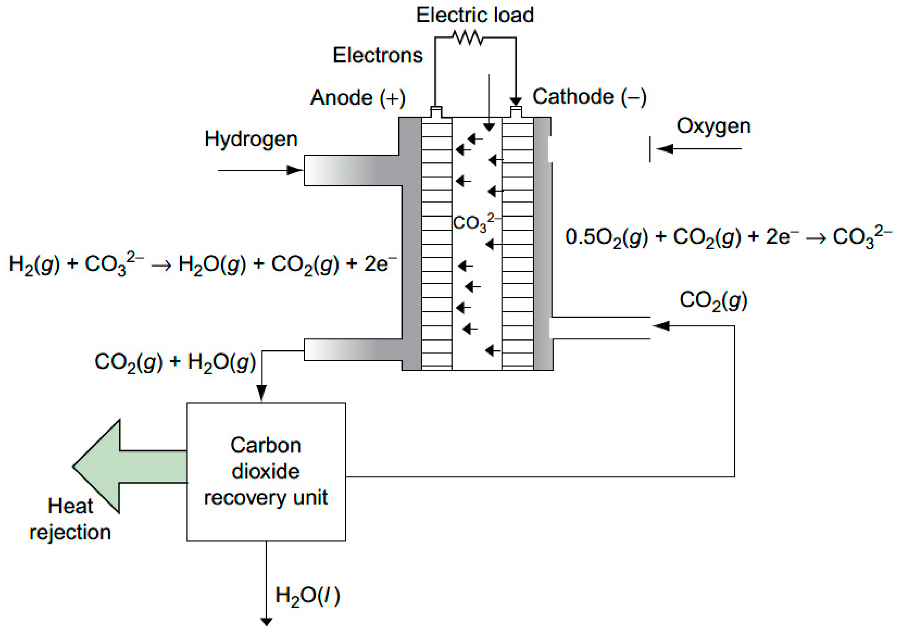
Molten Carbonate Fuel Cells (MCFC) are a type of fuel cell that has been identified as an effective way to capture CO
2 from exhausted gas. Like all fuel cells, when activated, they produce electricity due to two fundamental reactions: oxidation at the anode and reduction at the cathode. The typical MFCF operation process is shown in
Figure 1 and described below.
MCFCs rely on a mixture of carbonate salts as electrolytes. These cells must be heated to high temperatures, i.e., around 650 °C, in order to melt the carbonate salts and allow them to exchange ions through diffusion, enabling them to function as electrolytes.
For the basic reaction to occur within a MCFC, the anode must be supplied with a hydrogen-rich gas (H2) at a high temperature. This helps to dissolve the carbonate ions and allows them to act as electrolytes, while the hydrogen is oxidized into H+ ions.
The cathode, on the other hand, must be supplied with CO
2 to prevent the depletion of the carbonate ions that are produced through the reduction of oxygen bound to CO
2. These carbonate ions migrate from the cathode to the anode to restore the electrical balance within the system, where they react with H
+ ions to form carbonic acid (H
2CO
3). This acid is then broken down into CO
2 + H
2O, and the gas is released through an outlet. As a result, the CO
2 gas output is key for the MCFC that is captured from the system; it is processed in a plant specifically designed for purification and transformation into a liquid state. First, the raw CO
2 is pressurized through a series of compressors and treated with molecular sieves to remove moisture, which could potentially freeze in later stages of liquefaction. The compressed gas is then cooled with the help of a heat exchanger and a chiller, before being purified in specialized drums and separators. The result is CO
2 of 99.5% purity [
14,
41,
42,
43].
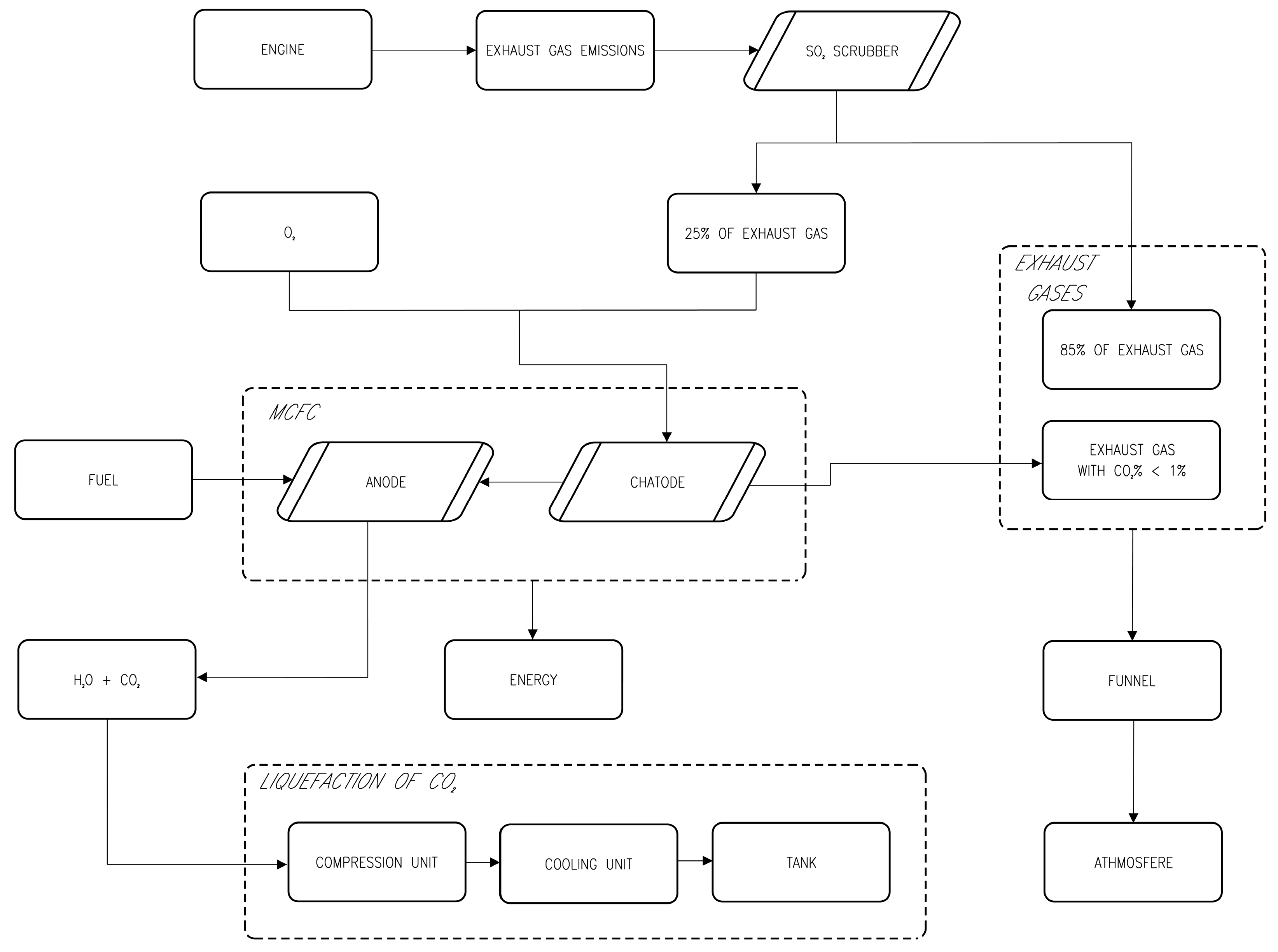
Through study of the available documentation regarding MCFC technology, the authors implemented a potential carbon capture system which would be suitable for installation on board a vessel, as illustrated in
Figure 2. Here, we can see the main elements of the system, as described above, combined with the ship engine system and related parts which are already installed.
The process begins with exhaust gases generated by the engine that are directed to an SO2 scrubber. About 25% of the exhaust gases, including CO2, are extracted, and combined with O2 in the cathode of the MCFC. The anode, on the other hand, is fueled by a fuel source. Since MCFCs operate using hydrogen (H2), any fuel such as LNG, bio-LNG, hydrogen, ammonia, syngas, and other fuels that provide hydrogen through external reforming/cracking or directly within the cell could be used on ships.
The output of the MCFC can be summarized as follows:
Efficient power generation for onboard auxiliaries;
The output of the anode will be H
2O + CO
2, which will be directed to a CO
2 liquefaction unit for further processing. The CO
2 will first be sent to a compression unit, then to a cooling unit, and finally, stored in a designated tank where it is kept in a liquid state at −40 °C and under 15 barg of pressure [
44]. CO
2 will then be discharged in port and transported to a storage site;
The output of the cathode will be exhaust gas with a CO2 concentration <1% that will be released, along with the untreated exhaust gas, into a funnel and then into the atmosphere.
3.2. Carbon Capture System with Amine
Post-combustion carbon capture using amine solvents is a widely accepted technology. The process involves using amines as solvents to capture CO
2 from the flue gas stream [
45,
46].
Amines are a class of organic compounds that contain nitrogen atoms bonded to one or more carbon atoms. They can be divided into three main categories: primary, secondary, and tertiary amines. Primary amines have nitrogen bonded directly to one carbon atom, while secondary amines have nitrogen bonded to two carbon atoms, and tertiary amines have nitrogen bonded to three carbon atoms. Some amines, including primary and secondary amines, can react with CO
2 to form carbamates through a process in which the nitrogen loses an electron and bonds to CO
2. However, tertiary amines can also react through a hydrolysis process in which water splits the compound, catalyzing the formation of a hydrogen carbonate ion (
), as shown in Equation (1) [
47,
48,
49].
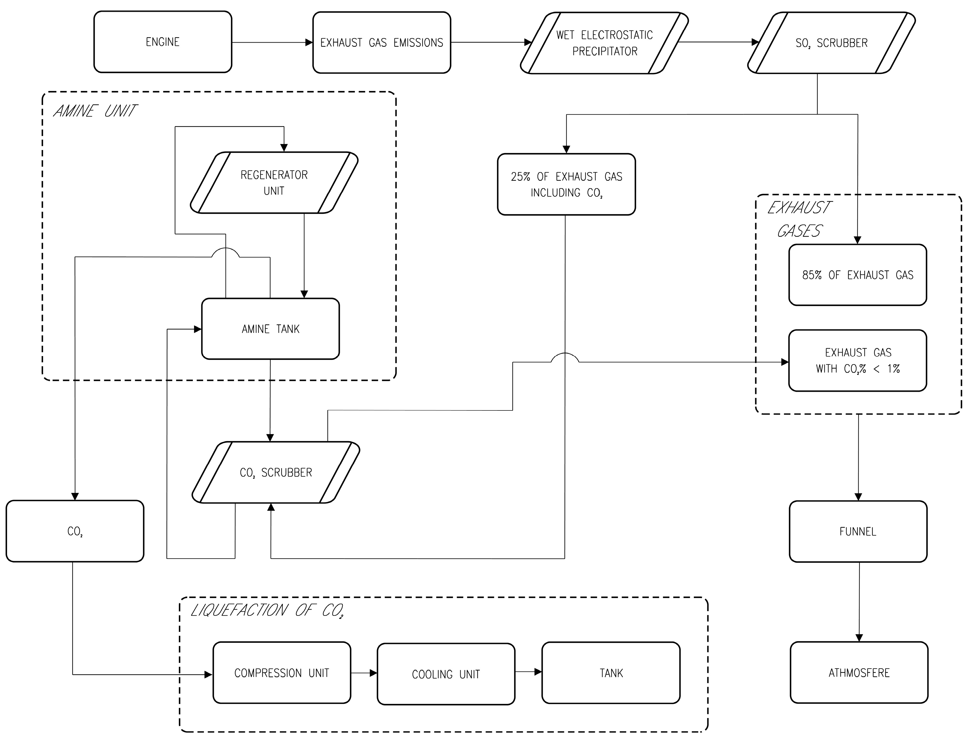
Here again, based on the documentation on amine technology [
7,
35], the authors devised a potential carbon capture system which would be suitable for installation on board a vessel, as illustrated in the
Figure 3. Here, we can see the main elements of the system, as described above, combined with the engine system and related parts which are already installed.
The exhaust gases emitted from the engine are directed toward an electrostatic precipitator, which serves to minimize the carry-over of dust and SO3. The exhaust gases then pass through an SOx Scrubber, and approximately 25% of the exhaust gases, including CO2, are input into a CO2 scrubber.
The exhaust gases are fed into the lower part of the CO2 scrubber and flow toward the ammonia solution which has been pumped through a recirculation pump from the designated tank and introduced into the upper part of the CO2 scrubber. The amine solution is first passed through a filter that collects the fine impurities that may be carried by the solution.
The outputs of the CO2 Scrubber are the following:
Exhaust gas with a CO2 concentration <1% will be released, along with the untreated exhaust gas, into a funnel and then into the atmosphere;
A flow of amine solution with CO2 that is sent to the amine tank.
The output of the amine tank will be CO
2 which is rich in amine; this will be taken from the top of the amine tank and sent to a regeneration unit. This stream is first heated (typically to 140–160 °C) and the amine solution flows downward into the regeneration unit, which is kept under vacuum, and comes into contact with a phase consisting of CO
2 and steam. Steam is used to improve the desorption of CO
2. The fluid returns to the amine tank, and the regenerated amines flow to the lower part of the amine storage tank due to gravity. Non-condensable gases (mainly CO
2) end up in the upper part of the amine tank and are then extracted and sent to the liquefaction unit for further processing. The CO
2 will be treated as in the system with MCFC described above and then disposed of in storage sites [
44].
3.3. Carbon Capture System with Calcium Hydroxide
It has been demonstrated that a calcium hydroxide solution Ca(OH)
2 has a significant potential to be utilized as an absorbent for capturing CO
2 [
50,
51].
Calcium oxide, or CaO, is a chemical compound known for being a white or grayish solid. Calcium hydroxide, or Ca(OH)
2, also known as slaked lime, is another chemical compound with a similar appearance, formed by the reaction of calcium oxide (CaO) with water. This reaction is typically exothermic and can be described through Equation (2):
Here, CaO and H
2O combine to form calcium hydroxide (Ca(OH)
2) and heat. This reaction can be carried out by mixing a slurry of CaO with water or by adding water to CaO powder [
52].
Carbon capture systems applying this process work by absorbing CO
2 from flue gases (i.e., emissions from power plants, industrial processes, ship engine) and converting it into calcium carbonate (CaCO
3) through a chemical reaction with calcium hydroxide (Ca(OH)
2), as in Equation (3):
The calcium carbonate can then be disposed of or used for various applications, such as building materials.
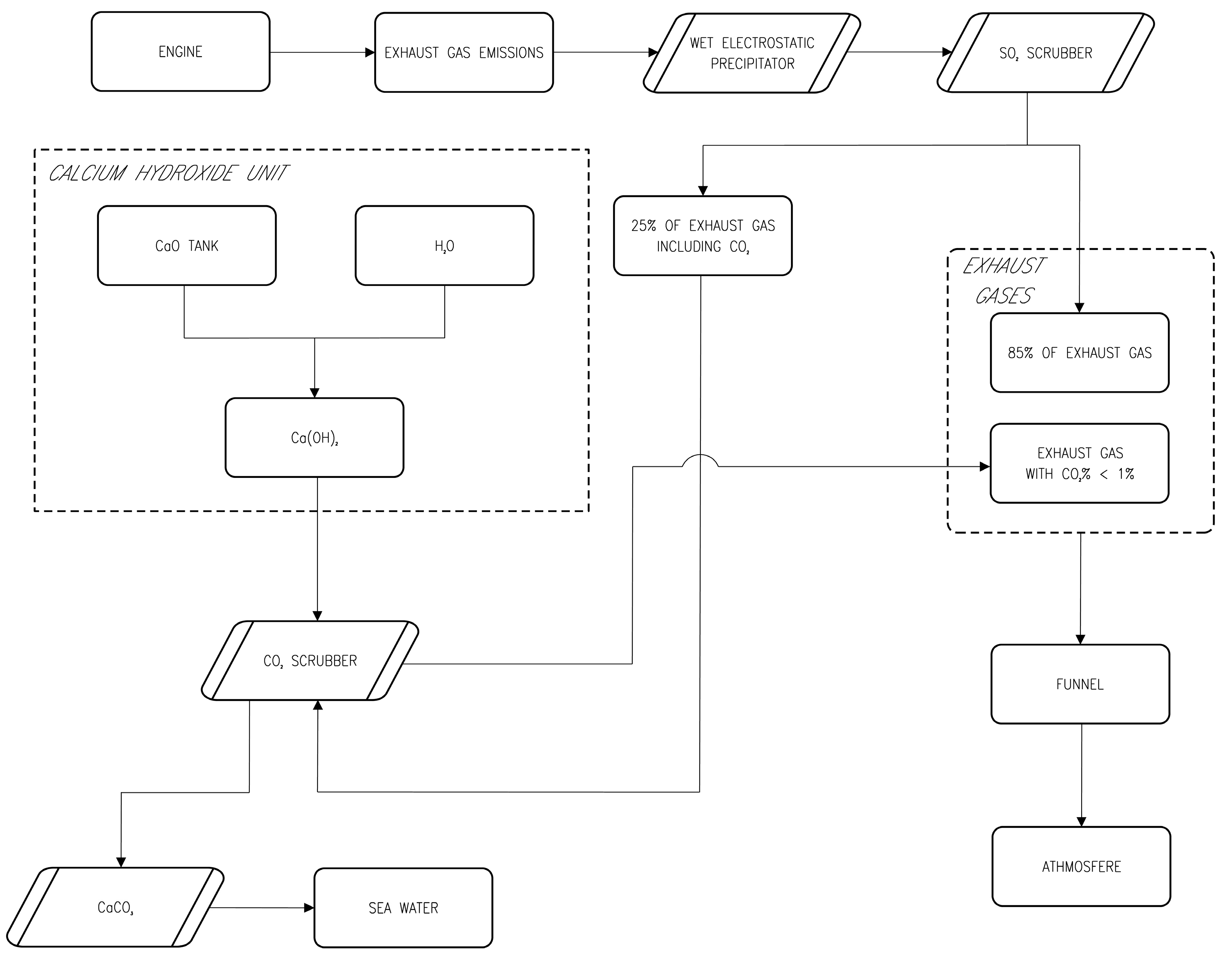
Once again, for Calcium Hydroxide technology, the authors used the available documentation [
50,
51,
53] to design a potential carbon capture system which would be suitable for installation on board a vessel, as illustrated in the
Figure 4. Here, we can see the main elements of the system as described above, combined with the engine system and related parts which are already installed.
The process begins with exhaust gases generated by the engine that are directed to a wet electrostatic precipitator which minimizes the carry-over of dust and SO3 that could lead to the early deterioration of the wet solution. The gases are then directed to an SO2 scrubber. There, 25% of the exhaust gases, including CO2, are extracted, and directed into the lower section of the CO2 scrubber, with a closed loop process.
The CaO which is bunkered and stored in an onboard tank as a solid bulk powder is extracted and reacts with H2O, forming Ca(OH)2.
The Ca(OH)2 is injected directly into the top of the CO2 scrubber. The exhaust gases that enter the lower portion of the scrubber flow counter-current to the calcium hydroxide suspension. This causes the exhaust gases to be washed with the calcium hydroxide suspension. The calcium hydroxide reacts with the CO2, forming calcium carbonate (CaCO3) and water H2O, as in Equation (3).
The output of the CO2 Scrubber will be the following:
Exhaust gas with a CO2 concentration <1% that will be released, along with the untreated exhaust gas, into a funnel and then into the atmosphere;
Fine grains of calcium carbonate (CaCO3), which is a slightly soluble in water and eco-friendly material that will be directly discharged overboard.
4. Discussion
The study and proposal of potential systems for the application of the above-mentioned carbon capture technologies on commercial ships has led the authors to perform two evaluations based on various system configurations and different Technology Readiness Levels (TRL). The knowledge given in this article lays the basis for further case studies that may offer valuable technical and economic data for the integration of onboard CCS technologies.
For the first aspect, the proposed systems were compared in terms of their components and the subsequent impact of their installation on board ships. In particular, it is evident that all three systems have a significant SOx scrubber installation footprint. However, among the three solutions, the calcium hydroxide capture system stands out, as it does not require any onboard space for CO2 storage, resulting in substantial space savings. The carbon capture system with MCFC and its functioning process also necessitate the use of H2 fuel or alternative sources such as LNG, bio-LNG, ammonia, or syngas, which results in the need for bulky and complex storage tanks. Additionally, if a reforming/cracking process is required to produce H2, the footprint will considerably increase, which is a crucial consideration for the selection purposes. However, more precise information could be obtained with future developments and once the various systems have been installed on ships.
For the second aspect, the Technology Readiness Level was evaluated to highlight the most promising systems for implementation within the maritime sector in the near future. The TRL for each proposed solution was evaluated on the basis of the information received by the supplier of the systems (i.e., Ecospray Technologies S.r.l.), which was qualitatively examined. For each system, all the component elements were studied based on their level of complexity, functioning process, dimensions, and ease of installation and integration on board ships; all component elements were then assigned a TRL grade. The TRL of the whole system was subsequently evaluated as a cumulative total. The three systems were ranked from the highest TRL (assigned to the solution that could be most easily installed on ships) to the lowest TRL (assigned to the solution that offers the most difficult challenges to overcome). The outcomes of this analysis are reported in the following sections in a descending order, i.e., from the highest to the lowest TRL.
4.1. Highest TRL
The highest TRL was evaluated for the Calcium Hydroxide carbon capture system. Indeed, this is the simplest solution among the three from a technological point of view and has the advantage of not requiring too much space on board. This technology could be suitable for bulk carriers that are already equipped for the onboard storage of the chemical reagent (CaO), as this would ensure a constant supply of the reagent that is necessary for the functioning of the carbon capture technology. Additionally, Calcium Hydroxide technology has the advantage of not requiring space for the on-board storage of CO2, since the output substance (CaCO3) could be potentially released into the marine environment without causing any damage.
However, CCS with Calcium Hydroxide also presents three important limitations. Firstly, the source of CaO has traditionally primarily been natural limestone, but its extraction process is highly energy-intensive and leads to an increase in CO2 emissions. Therefore, solutions requiring low energy consumption for the production process of quicklime should be imperatively studied to consider the technology in terms of its environmental sustainability throughout its entire life cycle. The second issue is the availability of calcium oxide in ports, which may be a challenge in non-equipped structures or in the first stages of deployment. The final issue concerns the disposal of the large amounts of CaCO3 and water mixture that are generated. While these are not harmful and there are no regulations prohibiting the discharge of this product overboard, uncertainty may arise in this regard and cooperation with regulatory bodies should be envisaged to address the topic.
4.2. Medium TRL
The second most promising technology in terms of TRL is Carbon Capture System with Amine; however, these systems are also associated with high costs and some technical challenges which need to be overcome. Firstly, they require more space on board for both the system allocation and CO2 storage. Additionally, the disposal of CO2 presents significant problems related to the storage sites where it can be discharged. In fact, an availability analysis of existing and potential geological sites is fundamental in order to assess the presence of a sufficient number of sites. Currently there are limited options available; most storage sites require the injection of CO2 deep underground into geological formations, which can be challenging and costly. Additionally, transportation processes must be effectively implemented. A further complication lies in the necessity for CO2 to be compressed to high pressures or liquefied in order to be transported, with consequent additional costs.
4.3. Lower TRL
The worst technology in terms of TRL is Carbon Capture System with MCFC. This could be seen as controversial, since MCFCs are suitable for all types of ships, thanks to their ability to effectively capture CO2, even at low concentrations. Additionally, these systems are characterized by particularly low operational costs. However, such systems have limitations due to the use of fuel cells, principally related to the required space and the complexity of the technology. Moreover, since they are fueled with H2, it is crucial to ensure both the availability in ports of such fuel or other H2 sources, like LNG, bio-LNG, ammonia, or syngas, and the correct logistics and bunkering chain for ships. As an additional obstacle, when relying on other fuels for the production of H2, the complexity related to the reforming/cracking system must be taken into account. Last but not least, this technological solution presents the same issues with regards to onboard storage, port disposal, transportation, and the permanent storage of CO2, as previously presented for amine-based carbon capture technology.
5. Conclusions
Given the importance of addressing the climate change problem and proposing potential solutions and measures to counter this phenomenon, new regulations have been put in place to decrease greenhouse gas emissions in the maritime industry. Despite the possibility of future CO2 emission taxes being implemented, this study is focused on Carbon Capture technologies that could find fruitful application on board ships. The use of these technologies presents both opportunities and challenges. On one hand, it could significantly assist in achieving emission reduction goals, funding efforts toward mitigating climate change, and improving the public’s perception of the shipping industry’s environmental impact. On the other hand, the technology is complex and costly, and, in most cases, the captured carbon system requires a proper storage space and disposal measures to minimize environmental and safety risks. Additionally, the technology may have implications for the weight and balance of ships and may affect their stability and safety. For all these reasons, the choice of a carbon capture system on a ship must be carefully considered, evaluating all the potential implications.
In order to inform shipowners in making such decisions, in this article, the authors examined various Carbon Capture Technologies at different Technology Readiness Levels (TRLs) that could potentially be applied on commercial vessels. Among the three systems analyzed, it was determined that Carbon Capture technology using Calcium Hydroxide appears to have the highest TRL and could be the first solution to find application on board ships. Hence, the importance of studying the impact of the technology on both new and aged ships is fundamental; in particular, the feasibility of performing refitting interventions on existing ships to modernize them and install the technologies necessary to comply with the new emissions challenges must be highlighted.
As carbon capture technology is not yet mature for use on ships, the authors studied the feasibility of the proposed systems in terms of their integration with existing machinery and outfitting in the current arrangement. We also proposed configuration diagrams to illustrate the correct implementation on board. These diagrams are not currently available in the literature, and systems descriptions can only be found with poorer details and completeness than the ones provided in the present article. Additionally, other assessments of TRL are not available in literature. Therefore, the present study may provide specific guidance for the application of Carbon Capture Technologies on board ships and makes a significant contribution toward the shipping decarbonization goal. Indeed, as a first indication of the carbon capture efficiency of the aforementioned systems for application on ships, supplier data states a potential reduction in CO2 emissions during a voyage of 20%. The actual efficiency has to be evaluated through calculations performed on a case-study ship, taking into account the specific energy consumption of the systems in correlation with the systems already installed on board. In fact, accurate data on the technical and economic feasibility of these technologies can only be provided once they have been integrated on study vessels, as various factors may affect the performance of CCS technologies.
Hence, future activities will be focused on studying this aspect, with the specific aim of applying the Calcium Hydroxide carbon capture technology on a container ship. The aim of such future developments will be twofold: firstly, the authors will evaluate the necessary modifications and interventions with regard to the allocation of the new system and its onboard integration with the components already present; secondly, we will evaluate the effectiveness of the Calcium Hydroxide carbon capture technology in terms of reducing CO2 emissions from shipping and determine the feasibility of implementing this technology on a commercial scale. In this way, shipowners will benefit from this research, as it will deepen our understanding of the potential benefits and drawbacks of the various carbon capture technologies for ships. In this regard, real data could provide guidance toward achieving a more sustainable future for shipping.
Author Contributions
Conceptualization, V.B. (Valentina Bortuzzo), S.B., V.B. (Vittorio Bucci); methodology, V.B. (Valentina Bortuzzo); validation, V.B. (Valentina Bortuzzo), S.B.; formal analysis, V.B. (Valentina Bortuzzo); investigation, V.B. (Valentina Bortuzzo); data curation, V.B. (Valentina Bortuzzo), S.B.; writing—original draft preparation, V.B. (Valentina Bortuzzo), S.B.; writing—review and editing, V.B. (Valentina Bortuzzo), S.B., V.B. (Vittorio Bucci); visualization, V.B. (Valentina Bortuzzo) supervision, S.B., V.B. (Vittorio Bucci); project administration, V.B. (Vittorio Bucci). All authors have read and agreed to the published version of the manuscript.
Funding
This research received no external funding.
Data Availability Statement
Data sharing is not applicable to this article.
Acknowledgments
The authors would like to thank Ecospray Technologies S.r.l. for its support and the documentation provided.
Conflicts of Interest
The authors declare no conflict of interest.
References
- Wang, Y.; Cao, Q.; Liu, L.; Wu, Y.; Liu, H.; Gu, Z.; Zhu, C. A review of low and zero carbon fuel technologies: Achieving ship carbon reduction targets. Sustain. Energy Technol. Assess. 2022, 54, 102762. [Google Scholar] [CrossRef]
- Ajayi, T.; Gomes, J.S.; Bera, A. A review of CO2 storage in geological formations emphasizing modeling, monitoring and capacity estimation approaches. Pet. Sci. 2019, 16, 1028–1063. [Google Scholar] [CrossRef]
- Ali, M.; Jha, N.K.; Pal, N.; Keshavarz, A.; Hoteit, H.; Sarmadivaleh, M. Recent advances in carbon dioxide geological storage, experimental procedures, influencing parameters, and future outlook. Earth-Sci. Rev. 2022, 225, 103895. [Google Scholar] [CrossRef]
- Bertagna, S.; Braidotti, L.; Bortuzzo, V.; Marinò, A.; Bucci, V. A fast feasibility tool for the assessment of fuel switch in the concept design of merchant ships. Procedia Comput. Sci. 2023, 217, 1386–1395. [Google Scholar] [CrossRef]
- Bortuzzo, V.; De Domenico, M.; Bucci, V. Strategies for Ship Decarbonisation: Technical Measure for Reducing Energy Efficiency Existing Ship Index. In Technology and Science for the Ships of the Future; IOS Press: Washington, DC, USA, 2022; pp. 632–640. [Google Scholar] [CrossRef]
- Ros, J.A.; Skylogianni, E.; Doedée, V.; Akker, J.T.V.D.; Vredeveldt, A.W.; Linders, M.J.; Goetheer, E.L.; Monteiro, J.G.M.-S. Advancements in ship-based carbon capture technology on board of LNG-fuelled ships. Int. J. Greenh. Gas Control. 2022, 114, 103575. [Google Scholar] [CrossRef]
- Chen, S.; Liu, J.; Zhang, Q.; Teng, F.; McLellan, B.C. A critical review on deployment planning and risk analysis of carbon capture, utilization, and storage (CCUS) toward carbon neutrality. Renew. Sustain. Energy Rev. 2022, 167, 112537. [Google Scholar] [CrossRef]
- Yadav, S.; Mondal, S. A review on the progress and prospects of oxy-fuel carbon capture and sequestration (CCS) technology. Fuel 2021, 308, 122057. [Google Scholar] [CrossRef]
- Arellano, Y.; Stavland, S.H.; Panduro, E.C.; Hamre, B.; Hjertaker, B.T. Imaging measurement technologies for CCS. In Proceedings of the 2022 IEEE 12th Sensor Array and Multichannel Signal Processing Workshop (SAM), Trondheim, Norway, 20–23 June 2022. [Google Scholar]
- Oh, J.; Anantharaman, R.; Zahid, U.; Lee, P.; Lim, Y. Process design of onboard membrane carbon capture and liquefaction systems for LNG-fueled ships. Sep. Purif. Technol. 2022, 282, 120052. [Google Scholar] [CrossRef]
- Zhang, Z.; Wang, T.; Blunt, M.J.; Anthony, E.J.; Park, A.-H.A.; Hughes, R.W.; Webley, P.A.; Yan, J. Advances in carbon capture, utilization and storage. Appl. Energy 2020, 278, 115627. [Google Scholar] [CrossRef]
- Zhang, K.; Lau, H.C.; Bokka, H.K.; Hadia, N.J. Decarbonizing the power and industry sectors in India by carbon capture and storage. Energy 2022, 249, 123751. [Google Scholar] [CrossRef]
- Shipping’s Future Role in Carbon Capture and Storage—DNV. DNV GL. 2022. Available online: https://www.dnv.com/expert-story/maritime-impact/Shippings-future-role-in-carbon-capture-and-storage.html (accessed on 12 January 2023).
- ECOSPRAY. Road to 2050. The Carbon Capture Technical Journal. Issue 01/2022. Available online: https://ecospray.eu/wp-content/uploads/2022/07/Road-to-2050_Issue_01.pdf (accessed on 28 December 2022).
- Güler, E.; Ergin, S. An investigation on the solvent based carbon capture and storage system by process modeling and comparisons with another carbon control methods for different ships. Int. J. Greenh. Gas Control. 2021, 110, 103438. [Google Scholar] [CrossRef]
- Wang, H.; Zhou, P.; Wang, Z. Reviews on current carbon emission reduction technologies and projects and their feasibilities on ships. J. Mar. Sci. Appl. 2017, 16, 129–136. [Google Scholar] [CrossRef]
- Negri, V.; Charalambous, M.A.; Medrano-García, J.D.; Guillén-Gosálbez, G. Navigating within the Safe Operating Space with Carbon Capture On-Board. ACS Sustain. Chem. Eng. 2022, 10, 17134–17142. [Google Scholar] [CrossRef] [PubMed]
- Feenstra, M.; Monteiro, J.; Akker, J.T.V.D.; Abu-Zahra, M.R.; Gilling, E.; Goetheer, E. Ship-based carbon capture onboard of diesel or LNG-fuelled ships. Int. J. Greenh. Gas Control. 2019, 85, 1–10. [Google Scholar] [CrossRef]
- CO2ASTS—Carbon Capture, Storage and Transfer in Shipping. A Technical and Economic Feasibility Study: Public Concise Report. Available online: https://conoship.com/wp-content/uploads/2020/06/200513-CO2ASTS-Public-Concise-Report.pdf (accessed on 14 April 2023).
- Bertagna, S.; Kouznetsov, I.; Braidotti, L.; Marinò, A.; Bucci, V. A Rational Approach to the Ecological Transition in the Cruise Market: Technologies and Design Compromises for the Fuel Switch. J. Mar. Sci. Eng. 2023, 11, 67. [Google Scholar] [CrossRef]
- Al Baroudi, H.; Awoyomi, A.; Patchigolla, K.; Jonnalagadda, K.; Anthony, E.J. A review of large-scale co2 shipping and marine emissions management for carbon capture, utilisation and storage. Appl. Energy 2021, 287, 116510. [Google Scholar] [CrossRef]
- European Commission. Proposal for a Regulation of the European Parliament and of the Council on the Use of Renewable and Low-Carbon Fuels in Maritime Transport; European Commission: Brussels, Belgium, 2021. [Google Scholar]
- Dong, J.; Zeng, J.; Yang, Y.; Wang, H. A review of law and policy on decarbonization of shipping. Front. Mar. Sci. 2022, 9, 2411. [Google Scholar] [CrossRef]
- Global Merchant Fleet—Number of Ships by Type 2018|Statista. Statista. 2018. Available online: https://www.statista.com/statistics/264024/number-of-merchant-ships-worldwide-by-type/ (accessed on 18 January 2023).
- Fragkos, P. Decarbonizing the International Shipping and Aviation Sectors. Energies 2022, 15, 9650. [Google Scholar] [CrossRef]
- Kirval, L.; Çalişkan, U.Y. Influence of the European Union (EU) on International Maritime Organization (IMO) about the Market-based Measures on Emissions. Int. J. Environ. Geoinform. 2022, 9, 146–153. [Google Scholar] [CrossRef]
- Gao, S.; Xin, X.; Li, C.; Liu, Y.; Chen, K. Container ocean shipping network design considering carbon tax and choice inertia of cargo owners. Ocean Coast. Manag. 2022, 216, 105986. [Google Scholar] [CrossRef]
- Sarbanha, A.-A.; Larachi, F.; Taghavi, S.-M.; Thiboutot-Rioux, M.; Boudreau, A.; Dugas, G. Mitigation of Ship Emissions: Overview of Recent Trends. Ind. Eng. Chem. Res. 2023, 62, 1707–1724. [Google Scholar] [CrossRef]
- Cullinane, K.; Yang, J. Evaluating the Costs of Decarbonizing the Shipping Industry: A Review of the Literature. J. Mar. Sci. Eng. 2022, 10, 946. [Google Scholar] [CrossRef]
- Carbon Taxes in the Shipping Industry—Assessing Japan’s Proposal. Available online: https://news.bloombergtax.com/daily-tax-report-international/carbon-taxes-in-the-shipping-industry-assessing-japans-proposal (accessed on 6 April 2023).
- European Council. Fit for 55. 2022. Available online: https://www.consilium.europa.eu/en/policies/green-deal/fit-for-55-the-eu-plan-for-a-green-transition/ (accessed on 18 January 2023).
- European Green Deal. Available online: https://www.consilium.europa.eu/en/policies/green-deal/#what (accessed on 12 December 2022).
- Soone, J. Fuel EU Maritime—Sustainable Maritime Fuels q4 2020 > Fit for 55 Package under the European Green Deal; Legislative Train 12.2022 1 A European Green Deal; European Parliamentary Research Service, EPRS: Brussels, Belgium, 2022; Available online: https://policycommons.net/artifacts/2685174/fueleu-maritime/3707786/ (accessed on 20 January 2023).
- Pape, M. Sustainable Maritime Fuels “Fit for 55” Package: The FuelEU Maritime Proposal. EU Legislation in Progress; European Parliament Research Service, EPRS: Brussels, Belgium, 2022; Available online: https://policycommons.net/artifacts/2325137/sustainable-maritime-fuels-fit-for-55-package/3085669/ (accessed on 20 January 2023).
- EU Emissions Trading System Directive (EU ETS). Marine & Offshore. Available online: https://marine-offshore.bureauveritas.com/sustainability/fit-for-55/eu-emissions-trading-system-directive#toc-what-is-eu-ets- (accessed on 11 January 2023).
- Gulbrandsen, L.H.; Wettestad, J. Carbon Pricing Under Pressure: Withering Markets? Politics Gov. 2022, 10, 230–234. [Google Scholar] [CrossRef]
- The International Transport Forum. Carbon Pricing in Shipping. Available online: https://www.itf-oecd.org/sites/default/files/docs/carbon-pricing-shipping.pdf (accessed on 8 December 2022).
- The Global Energy Crisis: Has Net Zero Been Sidelined?—DNV. DNV. 2022. Available online: https://www.dnv.com/power-renewables/publications/podcasts/the-global-energy-crisis.html?utm_campaign=ES_ADV_GLOB_22Q4_PROM_Podcast_S13_EP2_Openers&utm_medium=email&utm_source=Eloqua (accessed on 3 January 2023).
- Rajabloo, T.; Valee, J.; Marenne, Y.; Coppens, L.; De Ceuninck, W. Carbon capture and utilization for industrial applications. Energy Rep. 2023, 9, 111–116. [Google Scholar] [CrossRef]
- Buirma, M.; Vleugel, J.; Pruyn, J.; Doedée, V.; Schott, D. Ship-Based Carbon Capture and Storage: A Supply Chain Feasibility Study. Energies 2022, 15, 813. [Google Scholar] [CrossRef]
- Dincer, I.; Bicer, Y. 4.22 Electrochemical Energy Conversion. Compr. Energy Syst. 2018, 4, 856–894. [Google Scholar] [CrossRef]
- Nhuchhen, D.R.; Sit, S.P.; Layzell, D.B. Towards net-zero emission cement and power production using Molten Carbonate Fuel Cells. Appl. Energy 2021, 306, 118001. [Google Scholar] [CrossRef]
- Dicks, A.L. Molten carbonate fuel cells. Curr. Opin. Solid State Mater. Sci. 2004, 8, 379–383. [Google Scholar] [CrossRef]
- ECOSPRAY. Road to 2050 The Carbon Capture Technical Journal. Issue 02/2022. Available online: https://ecospray.eu/wp-content/uploads/2022/07/Road-to-2050_Issue-02.pdf (accessed on 28 December 2022).
- Parekh, A.; Chaturvedi, G.; Dutta, A. Sustainability analyses of CO2 sequestration and CO2 utilization as competing options for mitigating CO2 emissions. Sustain. Energy Technol. Assess. 2023, 55, 102942. [Google Scholar] [CrossRef]
- Hendry, J.; Lee, J. Miniaturizing amine-based carbon capture with heat-pipe intercooled rotating packed beds. In Proceedings of the 16th International Conference on Greenhouse Gas Control Technologies, GHGT-16, Lyon, France, 23–27 October 2022. [Google Scholar]
- Block, E.; Peter, A.S.S. “amine”. Encyclopedia Britannica, 6 February 2018. Available online: https://www.britannica.com/science/amine (accessed on 12 January 2023).
- Amines—Structures and Names. Chemistry LibreTexts. 2014. Available online: https://chem.libretexts.org/Bookshelves/Introductory_Chemistry/Basics_of_General_Organic_and_Biological_Chemistry_(Ball_et_al.)/15%3A_Organic_Acids_and_Bases_and_Some_of_Their_Derivatives/15.10%3A_Amines_-_Structures_and_Names (accessed on 8 January 2023).
- Yamada, H. Amine-based capture of CO2 for utilization and storage. Polym. J. 2020, 53, 93–102. [Google Scholar] [CrossRef]
- Han, S.-J.; Yoo, M.; Kim, D.-W.; Wee, J.-H. Carbon Dioxide Capture Using Calcium Hydroxide Aqueous Solution as the Absorbent. Energy Fuels 2011, 25, 3825–3834. [Google Scholar] [CrossRef]
- Mohd Daud, F.D.; Sreekantan, S.; Mohamed, A.R. Carbon Dioxide Capture at Various Temperatures Using Ca(OH)2 Sorbent Fabricated by Sol-Gel Route in Ethanol Media. Adv. Mater. Res. 2014, 1024, 35–38. [Google Scholar] [CrossRef]
- Calcium—Compounds|Britannica. In Encyclopædia Britannica. 2019. Available online: https://www.britannica.com/science/calcium/Compounds (accessed on 24 January 2023).
- ECOSPRAY. Decarbonization: Carbon Capture Technologies for Shipping; ECOSPRAY: Alzano Scrivia, Italy, 2022; Available online: https://ecospray.eu/it/landing-carbon-capture/ (accessed on 28 December 2022).
| Disclaimer/Publisher’s Note: The statements, opinions and data contained in all publications are solely those of the individual author(s) and contributor(s) and not of MDPI and/or the editor(s). MDPI and/or the editor(s) disclaim responsibility for any injury to people or property resulting from any ideas, methods, instructions or products referred to in the content. |
© 2023 by the authors. Licensee MDPI, Basel, Switzerland. This article is an open access article distributed under the terms and conditions of the Creative Commons Attribution (CC BY) license (https://creativecommons.org/licenses/by/4.0/).


