1. Introduction
Technical challenges currently inhibit the widespread deployment of renewable electricity generation. In particular, the low-density, time variability, and geographic dispersion of renewable sources make it difficult to integrate into Canada’s electricity grid. A potential solution to overcome the challenges facing integration of renewables is grid-scale energy storage.
One storage technology that is low on the development curve but possesses several characteristics which may make it a valuable option is thermochemical energy storage (TCES). In comparison with sensible and latent heat storage systems, TCES has an energy density 5–10 times higher, potentially allowing for more compact energy storage. As the products of the charging reaction can be stored at ambient temperature, the storage period is theoretically unlimited, which may make it suitable for long-term energy storage [
1,
2]. The projected cost is comparable to pumped hydro, which is a commercial technology but limited by geography, and is significantly lower than flywheel storage, which is currently being deployed in Ontario [
3,
4].
A class of materials that meet the necessary criteria for thermochemical energy storage are carbonates. The general form of the carbonation/calcination reaction is the reaction is driven by the system temperature and the partial pressure of CO
2,
and can occur at temperatures above 450 °C [
2]. For example, the reversible reaction of calcium oxide (CaO) with CO
2 to calcium carbonate, CaCO
3, proceeds as follows [
5]:
The equilibrium partial pressure of CO
2 is related to temperature as per Equation (3), where pressure is in bar (a) and temperature is in °C [
5].
The calcium looping (CaL) process has been investigated extensively for the purpose of post-combustion CO
2 capture. It offers potential benefits in comparison to more mature CO
2 capture technologies as the projected efficiency penalty is lower (6–8% points as opposed to 8–12.5% points for amine scrubbing or oxy-combustion technologies). However, deployment of this process has been hindered in part by the tendency of natural limestone to deactivate after relatively few cycles under CO
2 capture conditions, caused by rapid sintering and attrition of the particles exposed to high temperatures and heating rates in the calciner [
5]. The CO
2 carrying capacity drops significantly within only 20 cycles, reaching a low residual carbonation conversion, typically below 10% after 75 to 100 cycles [
5,
6]. To mitigate the effects of sorbent deactivation, it may be necessary to implement a sorbent purge and make up with fresh sorbent [
7].
More recently, the CaL process has been investigated for integration with concentrated solar power (CSP) in order to decouple the availability of sunlight from the production of electricity (CSP-CaL). Although the current installed capacity of CSP is only about 1/10 that of photovoltaic (PV) solar power, it has some features that may lead to further deployment, including the fact that it generates high-temperature heat, making it suitable to couple with a thermochemical system with a high turning temperature, such as the CaL process [
8]. At the laboratory scale, extensive testing has been conducted to determine the suitability of the CaL process for TCES, with a focus on the kinetics [
9,
10] and the multicyclic CaO conversion [
11,
12], as these will differ under energy storage conditions compared to post-combustion CO
2 capture conditions.
Further work has considered process integration of the CaL process with CSP technology [
13,
14,
15,
16,
17]. When considering these works, it can be noted that, with the direct CO
2 Brayton cycle integration schemes proposed, the pressure ratio in the main turbine is intrinsically linked to the absolute carbonator operating pressure. As a result, it is necessary to either operate the carbonator above atmospheric pressure or induce a vacuum at the turbine outlet in order to achieve an optimal pressure ratio. Operating the carbonator at elevated pressure necessitates the use of lock hoppers to transfer solids to and from the carbonator and the atmospheric calciner, in some cases at high temperature, which increases the technical complexity as well as the capital and operating costs. Further, in some cases the CO
2 stream exiting the carbonator may contain entrained solids that will need to be separated from the gas stream to the level of tolerance in the turbine. Solids removal equipment will entail additional complexity, as well as heat losses that will reduce the overall efficiency of the storage system.
Most recently, a configuration has been proposed in which a combined cycle, consisting of a CO
2 turbine and a heat recovery steam generator (HRSG), operates continuously. CO
2 is employed as a heat transfer fluid (HTF) in a closed loop on both the calciner and carbonator sides of the process. During daylight operation, the HTF is heated in a solar receiver and circulated through a heat exchanger in the calciner, driving the calcination reaction, before being circulated to the combined cycle. During nighttime operation, the HTF is circulated through a heat exchanger in the carbonator and heated by the carbonation reaction before being circulated to the combined cycle. The calciner is operated at atmospheric pressure and the carbonator is operated at 8 bar in order to have similar operating temperatures between the two reactors. The authors report an overall plant efficiency of 44.5% [
15]. This concept has been further extended to model more realistic operating conditions by incorporating a natural gas backup for continued turbine operation during solar transients [
16].
To address the technical barriers remaining for CSP-CaL, several projects have been conducted in recent years, including laboratory-scale work, simulation-based process modelling, and, more recently, pilot-scale research.
The SOCRATCES project is a planned pilot aimed at demonstrating the feasibility of the CSP-CaL integration and reducing the core risks associated with scaling up the technology. The project team includes the University of Seville, as well as a number of other European universities and technology developers and is funded by the European Commission’s Horizon 2020 Programme for Research and Innovation. The expected results of the project include: testing the system at TRL 5; demonstrating flash calcination technology at prototype scale; carbonator design with the possibility for scale-up and integration with a power block; analysis of attrition, agglomeration, and fouling; successful control of solids handling; and assessment of precursor materials and process conditions to allow high residual sorbent activity [
17].
Supported by the ELEMENTS program under the US DOE SunShot Initiative, a project titled “Regenerative Carbonate-Based Thermochemical Energy Storage System for Concentrating Solar Power” was conducted in 2015–2016 to overcome the limitations of residual CaO conversion. The researchers developed a synthetic reinforced CaO sorbent with a residual sorbent capacity around 0.3; however, fabrication of this material would significantly increase both cost and technical complexity of the CaL process [
18].
A follow-on to this project titled “Demonstration of High-Temperature Calcium-Based Thermochemical Storage System for use with Concentrating Solar Power Facilities” was funded by the US DOE’s APOLLO program and conducted between 2015 and 2018. The project focused on optimization and scale-up of the system, including validating the CaO sorbent for capacity, durability, and system economics. The researchers designed, fabricated, and commissioned a 4 kW
th pilot facility that included a closed-loop CO
2 system and a packed bed heat exchanger reactor. They were able to demonstrate operation of this system through short charging and discharging periods. They also conducted a techno-economic analysis (TEA) to estimate cost per kWh
th of energy stored, and translated this to an LCOE [
19]. In 2019, they attained a patent for the system [
20].
As an extension of the work that has been undertaken to date, a novel configuration, which decouples the carbonator pressure from the turbine pressure, enables atmospheric pressure operation of both the carbonator and the calciner, and supplies a stream of clean CO2 to a turbine, is proposed here. Decoupling the carbonator and turbine pressures allows for a multi-stage turbine with a pressure ratio that can be selected independently of the carbonator operating pressure, and eliminates the necessity presented in some configurations of operating the turbine outlet under vacuum. Further, operating the reaction and storage vessels at atmospheric pressure eliminates the requirement for high-temperature lockhoppering of solids.
2. Materials and Methods
For the purposes of comparison with similar systems being proposed, in this model, the energy input to the calciner is coming from CSP, and the carbonator is operated continuously with the calciner operating for 12 h in a 24 h period. However, the process configuration would be suitable for storing energy derived from any source operating at sufficiently high temperature to drive the calcination reaction. This could potentially include storing energy coming directly from the electricity grid via electrical heating in a fluidized bed calciner.
2.1. Overall Description
A process flow diagram of the proposed system is presented in
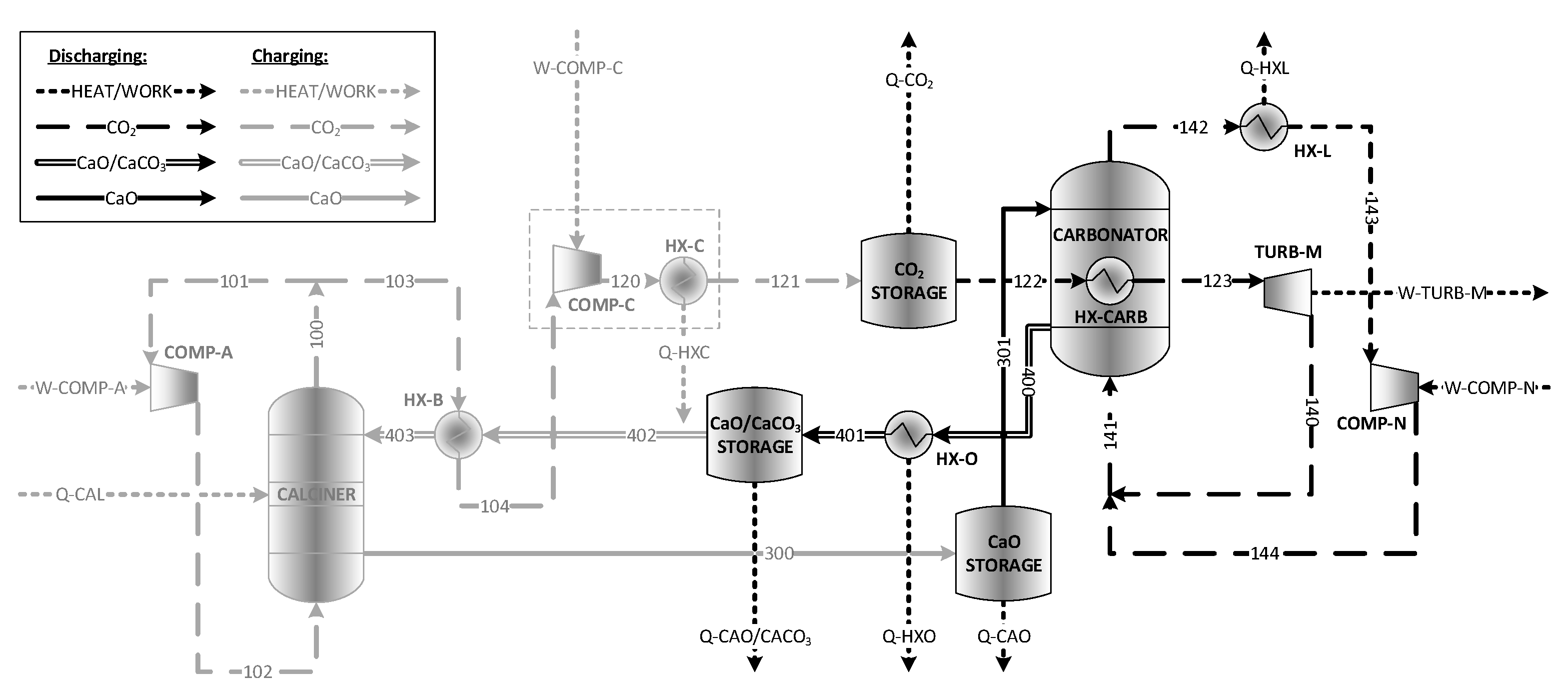
Figure 1, followed by a process description.
CO2 is stored under supercritical conditions at 7500 kPa (g) and ambient temperature in the CO2 storage tank, while CaO is stored at atmospheric pressure in the CaO storage tank. CaO enters the carbonator, where it undergoes a carbonation reaction with CO2 to produce CaCO3, as per Equation (2). The produced CaO/CaCO3 stream is then sent to storage in the CaO/CaCO3 storage tank. The unreacted CO2 exiting the carbonator is recycled.
The carbonation reaction supplies heat to the supercritical CO2 (sCO2) via an in-bed heat exchanger, which then enters an sCO2 power cycle. CO2 exits the power cycle and is combined with the CO2 exiting the recycle blower and recycled to the carbonator. The carbonator operates continuously to provide a constant power output over a 24 h period.
On the calciner side, CaO/CaCO3 exits the storage vessel and enters the calciner where the CaCO3 in the stream undergoes calcination to produce CaO and CO2. The CaO exits the calciner and enters the CaO storage vessel. The calciner operates over a 12 h period, with mass and molar flow rates on the calciner side being double those on the carbonator side.
CO2 exits the calciner and is split between being recycled to the calciner via the recycle blower and being sent to the CO2 compression train. It exits the compression train and enters the CO2 storage vessel.
Although the full design of unit operations is outside the scope of this work, consideration has been given to the different equipment options currently available at the commercial scale, as well as options that are currently under development.
2.1.1. Calciner
Calcination is a commercial technology used in cement production. Reactors currently used in this application are rotary kilns capable of operating at up to 2000 °C and producing around 3600 tons/day of CaO. Traditionally, heat is supplied to drive the calcination reaction via fossil fuel combustion. These reactors provide the necessary conditions for calcination to occur, including:
Although not yet commercial for CaL applications, other reactor types that can provide similar conditions include fluidized bed reactors and entrained flow reactors, which have been studied for application in both CO2 capture and energy storage applications.
A variety of fluidized bed technologies, as well as falling particle receivers and centrifugal particle receivers, have been proposed for CSP-CaL applications, and an extensive review of the state-of-the-art is provided by Tregambi et al. [
8]. The majority of the work thus far has been conducted at the laboratory scale. The SOLPART project, which ran from 2015–2019, moved the concept of solar calcination to the pilot scale. It was conducted with the goal of developing and implementing a high-temperature solar process for thermal treatment of particles, such as the calcination of limestone in the cement industry, to eliminate the need for combustion of fossil fuels for heat. Although this project does not have an energy storage component, the work on modelling and designing solar calciners will be significant to the continued development of CSP-CaL technology [
21,
22].
2.1.2. Carbonator
The conditions required for carbonation are similar to those required for calcination, with the distinction that longer residence times are required in order for CaO particles to reach their residual conversion values. Most carbonators proposed for CO
2 capture applications are fluidized bed reactors, although entrained flow reactors are being studied for both CO
2 capture and energy storage applications [
18].
2.1.3. Power Cycles
Steam Rankine cycles have been fundamental to the power industry for more than a century. The cycle efficiency is dependent on the steam temperature and pressure. Many modern high-efficiency steam plants utilize supercritical steam at up to 25,000 kPa (g) and 565 °C, and typically have efficiencies in the range of 42–44%. Facilities employing sub-critical cycles typically operate in the 38–42% efficiency range. Although many programs around the world are working to develop cycles that can exceed 50% efficiency, this will require deployment of new materials of construction, as currently used materials cannot sustain temperatures and pressures higher than those already achieved [
23].
The supercritical CO
2 (sCO
2) Brayton cycle has gained attention in recent years for application in power industries, including nuclear, solar, and fossil fuel. It naturally lends itself to integration with a CaL process, as CO
2 can be both a reactant and working fluid. Compared to a steam Rankine cycle, sCO
2 is less corrosive at similar temperatures, requires 10× smaller turbomachinery due to the high fluid density beyond the critical point, and can offer a thermal efficiency up to 5% higher. However, the turbine pressure ratio is smaller than in a steam Rankine cycle, leading to a relatively high turbine outlet temperature. This means that the thermal efficiency is highly dependent on the recovery of heat at the turbine outlet. A variety of layouts incorporating heat recuperation have been studied, with a recompression cycle leading to the highest efficiency [
24].
2.1.4. Storage Vessels and Solids Handling Equipment
Storage vessels are required for the CaO and CO
2 streams exiting the calciner, as well as for the mixed CaO/CaCO
3 stream exiting the carbonator. Ideally, these storage vessels should be as small as possible to reduce capital costs, with smaller storage tanks expected in comparison with current molten-salts-based solar power plants due to the higher storage density provided by the CaL process [
18]. If hot solids storage is implemented, the vessels will require insulation to minimize heat losses and increase overall process efficiency.
Handling of hot solids can add significant complexity to a power plant, especially in a case where there is the potential for solids to be under a reactive environment, as is the case with the CaL process. Options for conveying equipment include both mechanical systems and pneumatic systems, both of which include established technology options used in many applications. Mechanical systems typically have a higher investment cost but lower operating cost in comparison with pneumatic systems. Other important factors to consider are the ability of the equipment to avoid particle segregation by size and to maintain a low energy consumption [
18].
2.1.5. Heat Exchangers
Heat exchangers are essential to the proposed process in order to maximize use of sensible heat and thus maximize the overall process efficiency. Depending on the storage scenario being considered, the process may require both gas-solid and solid-solid heat exchangers. Gas-solid heat exchangers may be either direct or indirect, depending on the stream compositions and temperatures, in order to avoid unintended carbonation in heat exchange equipment. While different types of solid-solid heat exchangers have been proposed, including an indirect configuration employing a heat transfer fluid in direct contact with both solids streams, this equipment is not developed on the required commercial scale [
18].
2.2. Model Assumptions
To assess the relative merits of the proposed storage system, a process model was built in Aspen HYSYS V11. The following assumptions have been applied to all scenarios considered in this work:
The CaCO
3 in the stream entering the calciner undergoes complete decomposition to produce CaO and CO
2 [
5].
The change in gas velocity in the carbonator and calciner due to reaction is limited to 10% in order to maintain the desired fluid dynamic conditions.
The calciner operates isothermally at the equilibrium temperature, whereas the carbonator operates isothermally at 20 °C below the equilibrium temperature in order to maintain the driving force for carbonation while minimizing the required heat exchange surface areas.
The round-trip efficiency of the process is calculated over a 24 h period.
Gas/solid and gas/liquid heat exchangers have a minimum approach temperature of 15 °C [
25].
Solid/solid heat exchangers have a minimum approach temperature of 20 °C [
25].
Ambient temperature is 20 °C, and utility cooling water is available at 20 °C [
25].
Compressors have an adiabatic efficiency of 89%, and turbines have an isentropic efficiency of 75% [
25].
CaO and CaCO3 have a particle density of, respectively, 2000 kg/m3 and 2800 kg/m3 based on experimental measurements made at CanmetENERGY-Ottawa.
Solids (CaO, CaCO
3, and mixtures) have an average bed void fraction of 0.4 [
26].
Two possible configurations for implementing heat integration are considered based on the desired storage tank temperatures, which depend on the intended storage duration.
2.2.1. Configuration 1
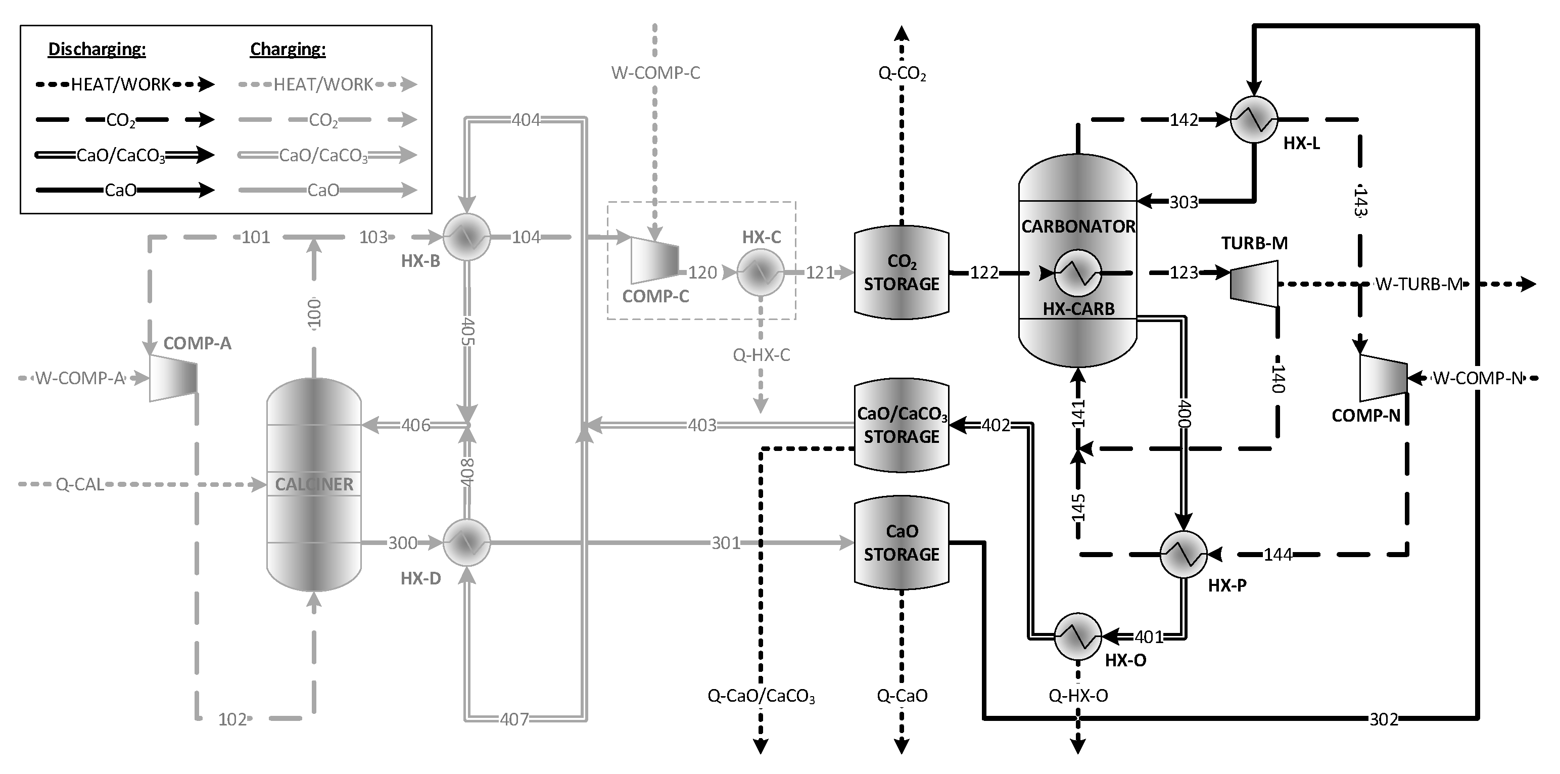
A process flow diagram for Configuration 1 is shown in
Figure 2. In this case, the calciner operates over a 12 h period and the carbonator over a 24 h period, meaning that material flow rates on the calciner side of the process are twice those on the carbonator side of the process, with the storage vessels acting as a buffer between the two sides. To maximize heat extraction on the carbonator side, solids exiting the calciner are not cooled, but instead are stored hot, with heat loss from the storage tank being accounted for. CO
2 and solids exiting the carbonator side have heat extracted in heat exchangers HX-L and HX-O, with this high-temperature heat being used to drive a supercritical steam power cycle in order to maximize power production.
A summary of base case inputs to the process model for Configuration 1 is presented in
Table 1. The power input to the calciner is used as the baseline for the assessment and is equal to 100 MW.
The main CO
2 compressor, represented in
Figure 2 as COMP-C and HX-C, is modelled as a multi-stage compressor with a maximum stage outlet temperature of 150 °C and interstage cooling provided by utility cooling water. This yielded a 4-stage compressor with each stage having a pressure ratio of 2.9. A fraction of the heat of compression is recovered to preheat Stream 402 before it enters HX-B, with the maximum temperature of this stream being fixed at 15 °C below the highest-temperature stream exiting a compression stage in COMP-C.
The round-trip storage cycle efficiency,
ηRT, can be calculated according to Equation (4):
The energy storage density,
ρE, can be calculated according to Equation (5):
2.2.2. Configuration 2
Configuration 2 was developed for scenarios in which long-term storage is required and would lead to unfavourably high heat loss from stored solids. A process flow diagram for this configuration is presented in
Figure 3. Heat recovery is maximized during both charging and discharging stages through addition of heat exchangers HX-D and HX-P. The recovery of heat in HX-P leads to lower-temperature heat being available from HX-O in comparison with Configuration 1; this heat is used to drive a subcritical steam power cycle.
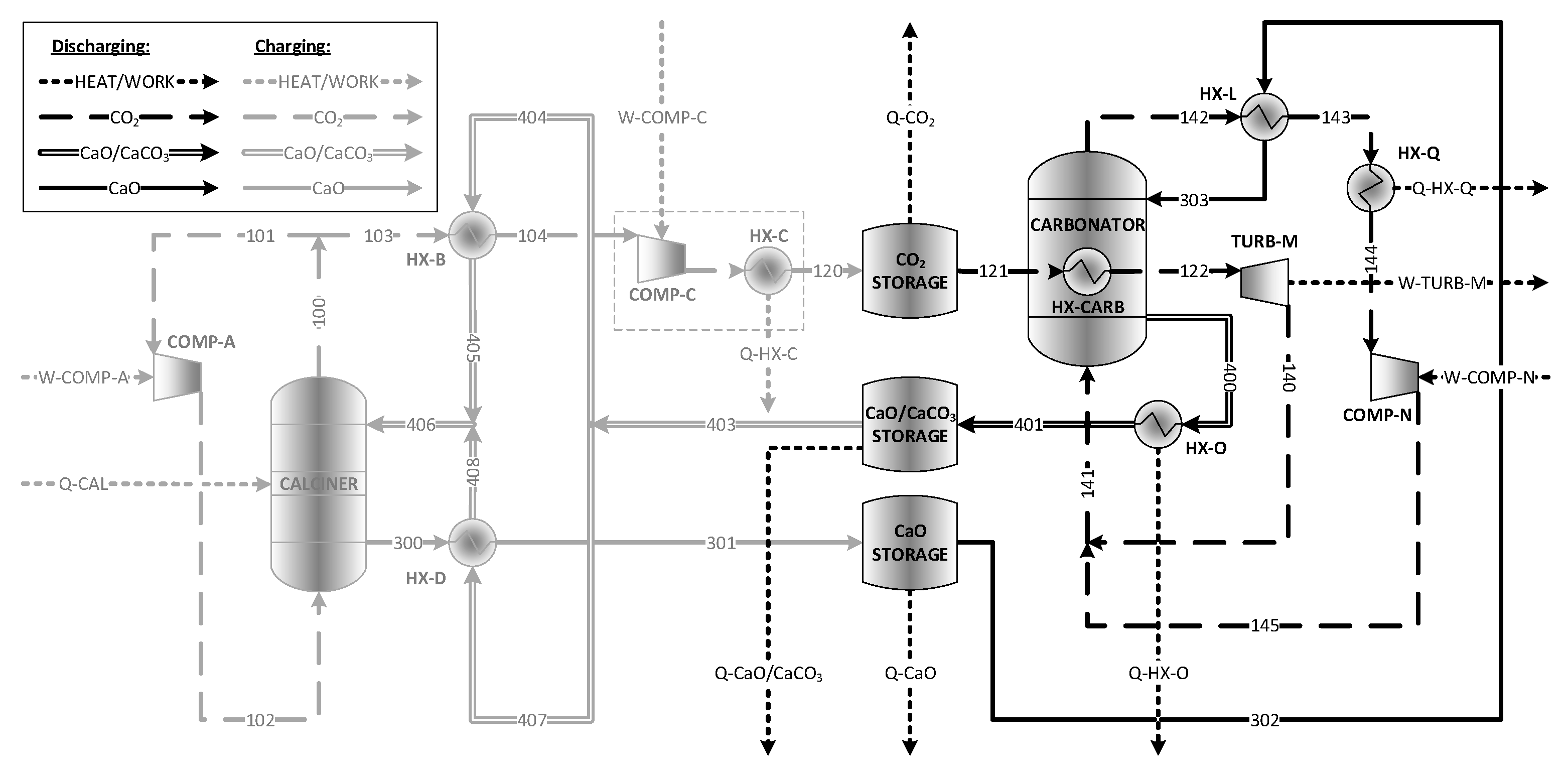
Analysis of Configuration 2 resulted in the observation that above a carbonator CaO conversion of approximately 0.42, the heat generated by the carbonation reaction exceeds what is being removed in TURB-M and HX-O. To continue the analysis beyond this conversion limit, a modified version of Configuration 2 was developed in which HX-P is replaced by a cooler, HX-Q, allowing for additional power generation on the carbonator side. This modification is shown in
Figure 4. Heat is recovered in HX-Q at a sufficiently high temperature to drive a supercritical steam power cycle. HX-Q is placed upstream of the recycle blower, COMP-N, to minimize the blower inlet temperature.
The energy storage density for Configuration 2 can be calculated using Equation (5), as with Configuration 1. The round-trip storage cycle efficiency can be calculated using Equation (6), and, for the modified version of Configuration 2, Equation (7) is used which includes the heat recovered in HX-Q.
As with Configuration 1, the main CO2 compressor is modelled as a multi-stage compressor with a maximum stage outlet temperature of 150 °C and interstage cooling provided by utility cooling water, yielding a 4-stage compressor with each stage having a pressure ratio of 2.9. A fraction of the heat of compression is recovered to preheat Stream 403 before it is split between HX-B and HX-D. At lower conversions, this heat recovery is limited by the temperature of Streams 405, 406, and 408, which cannot exceed 880 °C in order to prevent calcination occurring upstream of the calciner. At higher conversions, the reduced flow rate of Stream 403 means the quantity of heat recovered is again limited to 15 °C below the highest-temperature stream exiting a compression stage in COMP-C.
3. Results and Discussion
Base case material and heat stream summaries for Configuration 1 and Configuration 2 can be found in
Appendix A.
3.1. Effect of CaO Conversion in Carbonator
An analysis was conducted on the effect of CaO conversion in the carbonator on the round-trip efficiency over a 24 h period. The efficiency of the supercritical steam cycle operating with the heat extracted in HX-L, HX-O, and HX-Q was fixed at 40%, based on conventional and state-of-the-art steam cycle efficiencies [
23]. The results of this analysis are presented in
Figure 5.
For Configuration 2, resolution of the heat balance on the carbonator side can only be attained at a carbonation conversion of 0.11 or higher. Below this conversion, Stream 144 is too cold to be sufficiently preheated in HX-P. Further, there are two discontinuities in the round-trip efficiency. The first occurs at a carbonation conversion of 0.23. At this conversion, the temperature of Stream 401 exceeds 600 °C, making it possible for the heat extracted in HX-O to drive a supercritical steam cycle instead of a subcritical steam cycle. The second discontinuity occurs at a carbonation conversion of 0.42 and is due to the production of additional power in HX-Q.
As shown, at low conversions, the round-trip efficiency is higher for Configuration 1. However, once the conversion exceeds 0.23 and the temperature of Stream 401 is sufficiently high to drive a supercritical steam cycle, the round-trip efficiencies are comparable between the two configurations, as the production of energy in both configurations is then dominated by the supercritical steam cycle. Both configurations are competitive with those proposed in previous research, which has reported round-trip storage cycle efficiencies in the range of 38–46% [
15,
17].
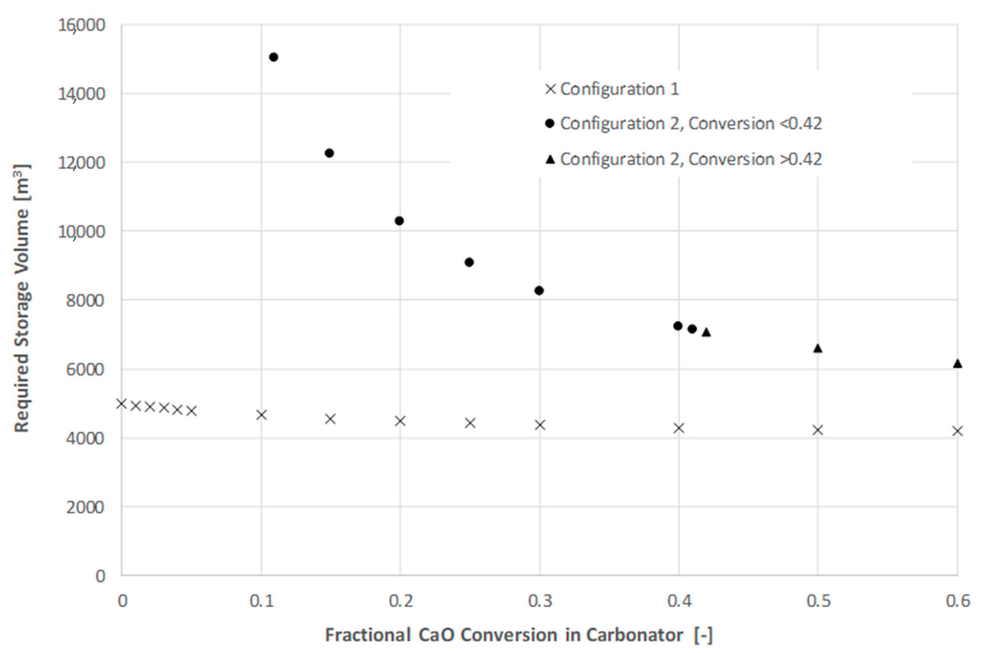
The effect of CaO conversion on the quantity of solids circulating in the process, and, thus, the required storage volume, was also investigated.
Figure 6 presents the required storage volume in Configuration 1 vs. Configuration 2 as a function of fractional CaO conversion in the carbonator.
As shown, the required storage volume is lower for Configuration 1, as well as a weaker function of conversion. For both configurations, the required storage volume decreases with increasing conversion as a result of the decreasing quantity of solids. The heat supplied to the calciner is split between sensible heating of the entering solids and the heat of calcination required to convert CaCO3 to CaO. When QCAL is held constant, increasing the fraction of CaCO3 to the calciner will necessarily lead to a decrease in total solids fed. As the quantity of solids circulating in the system decreases, so does the required storage volume, as well as the overall conveying duty.
The energy storage density of the system can be estimated from the combined volume of the CaO/CaCO
3 storage vessel, the CaO storage vessel, and the sCO
2 storage vessel. The literature reports storage densities based on reaction enthalpies in the range of 2.5–3.2 GJ/m
3 [
2,
27], while other sources report lower values when taking into consideration the need for separate storage vessels and the conversion in the carbonator [
28]. A recent analysis of storage density for CSP-CaL systems found energy density of the system ranged from 0.27 and 0.77 GJ/m
3 for carbonation conversion between 0.1 and 0.4 and with CO
2 storage at 75 bar [
14]. The storage density was found to be mainly dependent on the CO
2 storage conditions (temperature and pressure) and the carbonation conversion.
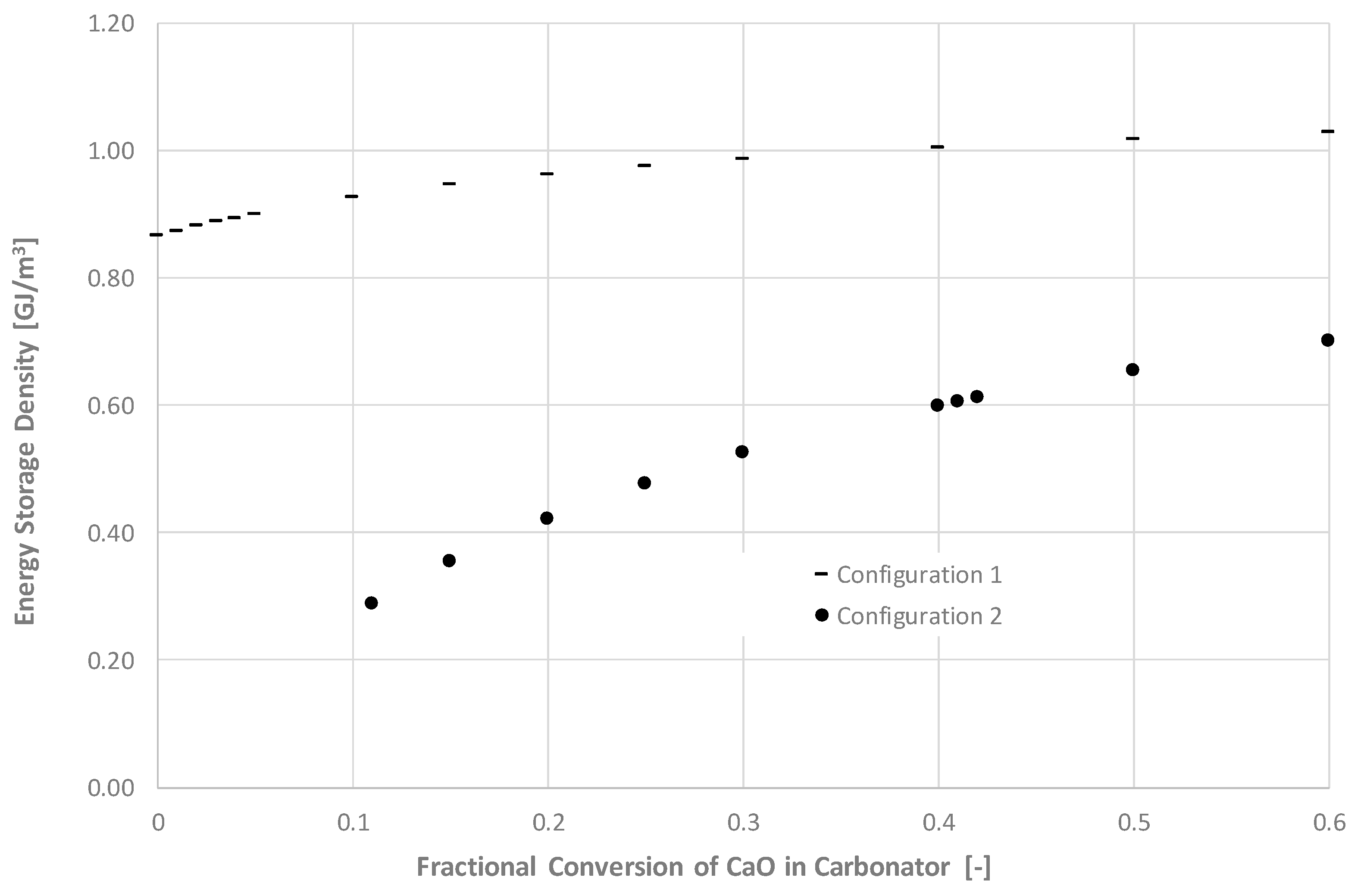
Figure 7 presents the energy storage density as a function of carbonation conversion for both Configuration 1 and Configuration 2. The results are comparable to those obtained by Ortiz et al. [
14], with the storage density ranging from 0.8–1.0 GJ/m
3 for Configuration 1 and 0.3–0.7 GJ/m
3 for Configuration 2.
As noted in
Section 1, the residual carbonation conversion of CaO has been studied extensively for applications in both CO
2 capture from combustion facilities and energy storage in CSP facilities. Much of the work conducted has been performed via TGA. Studies indicate that although CaO carbonation conversion drops rapidly under CO
2 capture conditions for combustion applications, higher values of residual conversion may be attained under energy storage conditions [
29]. However, the conditions considered for energy storage often include calcination under gas mixtures, including helium or steam, allowing for lower calcination temperatures due to the lower partial pressure of CO
2 in the gas mixture. These calcination conditions are not reflected in many of the process analyses conducted [
15,
30], which, instead, employ a 100% CO
2 atmosphere at 900 °C. Under these conditions, sorbent deactivation can be expected to be similar to that observed in CO
2 capture processes. The residual carbonation conversion will also typically be lower in full-scale operation than in TGA testing, due to the impacts of particle thermal stresses from operating the calciner as a fluidized bed. For example, pilot testing conducted over a 4 h period in a 100 kW
th calciner at 910 °C and under a 75% CO
2/5% N
2/20% O
2 atmosphere yielded a residual carbonation conversion of 0.07 [
31]. Pilot testing conducted at the 1 MW
th scale over several days, in which the calciner was operated as an oxy-fired combustor with recirculated flue gas, yielded a residual carbonation conversion below 0.05 [
32].
To attain the residual carbonation conversion required to operate in Configuration 2 (0.11), a number of options exist:
Implement a sorbent purge and make up with fresh sorbent. This would lead to increased process complexity as well as increased operating costs in order to provide a supply of fresh sorbent.
Use a modified sorbent. Many techniques have been developed to improve the thermal and mechanical stability of calcium-based sorbents, including the use of rigid porous carrier materials, additives, and the use of synthetic precursors. Recent work has shown that an acicular calcium and magnesium acetate precursor can yield a stable porous structure on the surface of calcium-based sorbents to permit an effective stable carbonation conversion up to 0.7 [
33].
Employ enhanced calcination conditions, such as a partial steam or helium environment, to reduce the CO2 partial pressure and thereby reduce the operating temperature required to satisfy the equilibrium and achieve suitably fast calcination. This would require separation of the gas mixture downstream of the calciner before the CO2 could be sent to storage; either via membrane for a He/CO2 separation or via condensation for a steam/CO2 separation. In addition to the required changes to the process configuration, this would have a significant impact on the calciner-side energy balance.
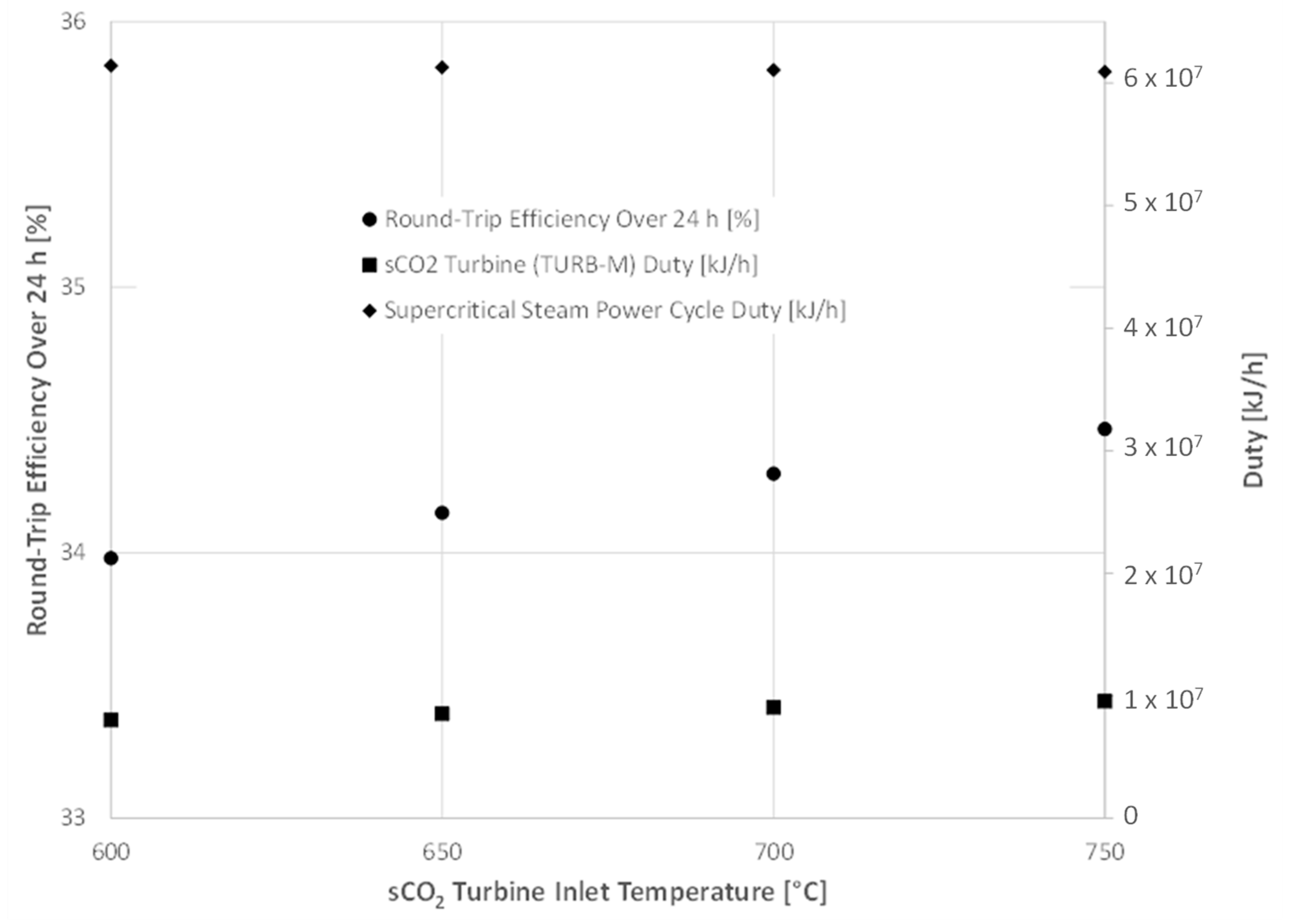
3.2. Effect of sCO2 Turbine Inlet Temperature
A sensitivity analysis was conducted on the inlet temperature to TURB-M, the sCO
2 turbine on the carbonator side, in Configuration 1. Temperature was varied from 600 to 750 °C, based on typical and advanced operating temperatures of sCO
2 power cycles [
34] Results are presented in
Figure 8.
Increasing the inlet temperature of the sCO2 turbine has a minimal impact on round-trip efficiency, with a temperature increase of 150 °C leading to an efficiency increase of only 0.5%. This is because increasing the sCO2 turbine inlet temperature, while increasing the power produced by the sCO2 turbine, decreases the amount of heat available to be extracted in HX-L, thereby decreasing the power produced by the supercritical steam cycle. The slight net increase can be attributed to a higher cycle efficiency in the sCO2 turbine than in the supercritical steam cycle.
3.3. Effect of Heat Loss in Solid Storage Vessels
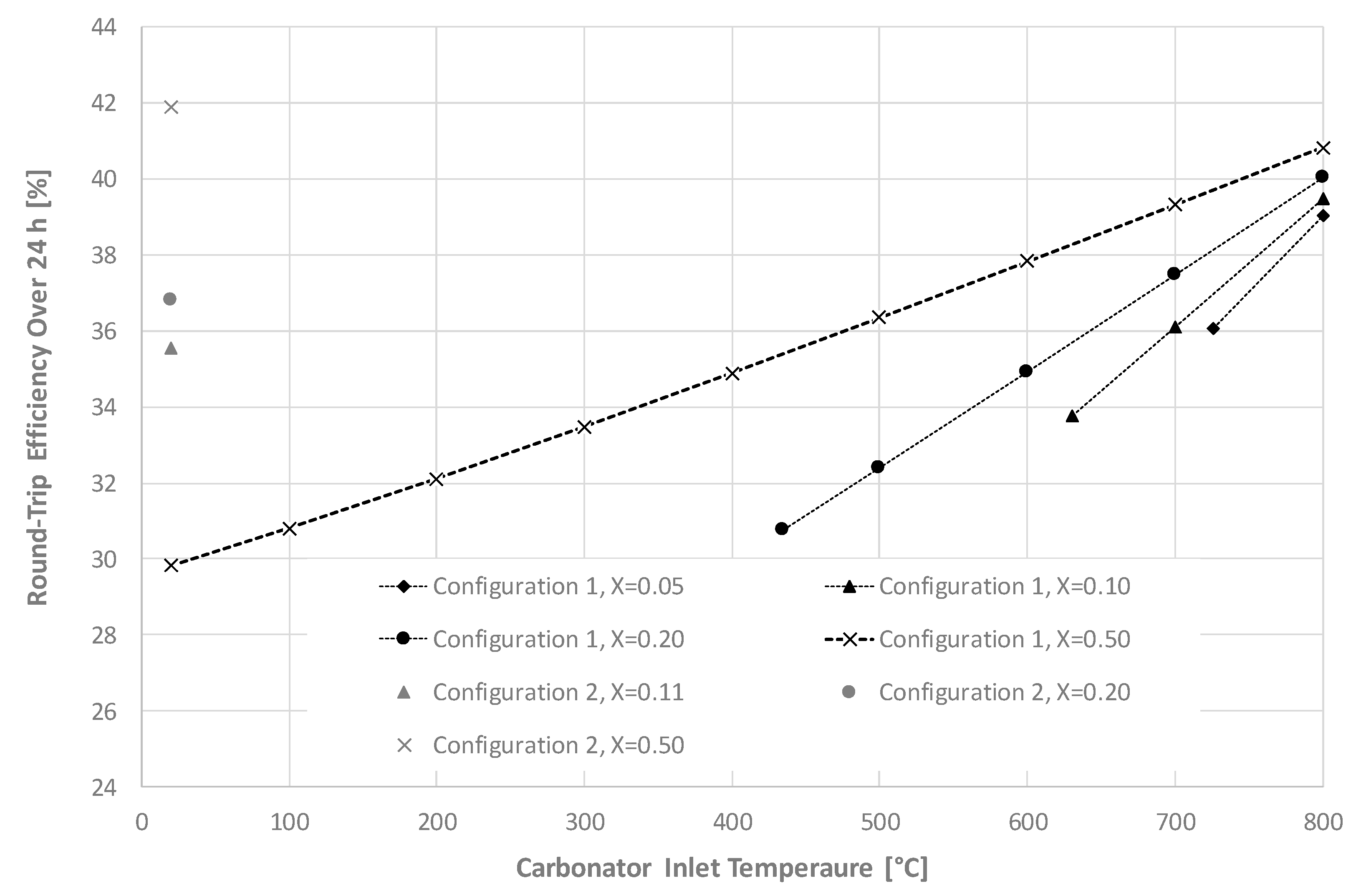
As shown in
Figure 2, in Configuration 1, heat is not recovered from the CaO stream exiting the calciner (Stream 300); instead, this stream is stored at high temperature. Heat loss can be expected to occur from the storage vessel during the base-case 12 h storage period, and given this fixed storage duration, the carbonator solids inlet temperature (Stream 301) will be determined by the rate of heat loss from the CaO storage vessel.
Figure 9 presents the round-trip efficiency for both Configuration 1 and Configuration 2 as a function of carbonator solids inlet temperature at different values of fractional CaO conversion, X.
As shown, for Configuration 1, the storage cycle efficiency increases rapidly with increasing carbonator inlet temperature, and the relationship is more pronounced at lower CaO conversions. However, lowering the CaO conversion introduces an operating limit on the carbonator inlet temperature. For example, at a conversion of 0.2, Stream 301 must enter the carbonator at a minimum temperature of 435 °C to satisfy the energy balance; dropping the conversion to 0.05 increases this minimum temperature requirement to 726 °C.
As noted previously, for Configuration 2, the energy balance requires a minimum conversion of 0.11. Above this minimum conversion, Configuration 2 will outperform Configuration 1 at lower carbonator inlet temperatures. For example, at a conversion of 0.2, a higher round-trip efficiency will be attained with Configuration 2 if a carbonator inlet temperature higher than approximately 680 °C cannot be attained with Configuration 1.
To determine what the carbonator solids inlet temperature will be after the 12 h storage period, the rate of heat loss from the storage vessel to the atmosphere can be estimated through a heat transfer analysis. This was carried out based on the assumption that the greatest resistance to heat transfer from the storage vessel will be at the surface, where heat loss will occur via free convection and radiation. This analysis represents a worst-case scenario where resistance to conductive heat loss through the vessel is neglected, and the vessel outer surface is assumed to be at the same temperature as the stored solids. The vessel is assumed to be a vertical cylinder with an L/D ratio of 3.
The rate of heat loss from the CaO storage vessel is estimated as the sum of the convective and radiative heat loss according to Equation (8):
The quantity of solids in the storage tank was calculated based on operation of the calciner for 12 h. A heat loss rate, in °C/h, was then calculated by rearranging Equation (9) for ΔT/t.
The results indicate that, for a carbonation conversion of 0.2, the heat loss rate starts at approximately 1.8 °C/h and decreases as the surface temperature of the vessel decreases. For a carbonation conversion of 0.05, the heat loss rate starts slightly lower, at 1.6 °C/h, due to the larger thermal mass of solids in the system. The carbonator solids inlet temperature is assumed to be the same as the CaO storage tank temperature. These low heat loss rates suggest that, after 12 h, the carbonator solids inlet temperature will not drop more than 20 °C below the calciner outlet temperature.
One of the noted benefits of thermochemical energy storage is its potential for theoretically unlimited storage durations, as the products of calcination are stable and can be stored at ambient temperature without deteriorating. For this reason, the process may be considered as a solution in circumstances where longer-term energy storage, such as seasonal storage, is required. To determine the storage duration that can be attained while still satisfying the energy balance for Configuration 1, the rate of heat loss from the solids storage vessel to the atmosphere calculated above can be used in combination with the minimum carbonator inlet temperatures obtained from
Figure 9.
Figure 10 shows the carbonator solids inlet temperature as a function of storage duration for Configuration 1. The results are shown for both the base case ambient temperature (
in Equation (8)) of 20 °C and an ambient temperature of −20 °C.
As shown, for a carbonation conversion of 0.2 and ambient temperature of 20 °C, the carbonator solids inlet temperature reaches the limit of 435 °C dictated by
Figure 9 after 455 h, or approximately 19 days. This limit is reached within 17.5 days if the ambient temperature is −20 °C. For a carbonation conversion of 0.05 and ambient temperature of 20 °C, the carbonator solids inlet temperature reaches the limit of 726 °C within 132 h, or 5.5 days. In this case, the limit is reached within 5.2 days if the ambient temperature is −20 °C. If longer storage durations were required, it would be optimal to use Configuration 2. However, it would be necessary to add additional process equipment, including auxiliary heating on the carbonator side for process start-up, which would add a significant efficiency penalty and make the system less competitive with other storage technologies. To determine the efficiency and overall competitiveness of the proposed system under long-term storage conditions, a transient analysis would be required to evaluate the start-up energy requirements.
4. Conclusions
The configuration of the CSP-CaL process proposed in this work offers some advantages to other proposed configurations. Operating both the calciner and the carbonator at atmospheric pressure eliminates the need for lockhoppering of hot solids, which reduces the process complexity. Configuration 1 further offers the elimination of solid–solid heat exchangers. Further, the separation between the main turbine working fluid and the carbonator enables decoupling of the turbine pressure and the carbonator pressure. To fully assess the benefits of operating the turbine in this configuration, including the potential to implement interstage reheating and increase overall efficiency, further analysis of the power cycle would be required. On the other hand, with the proposed systems, a significant amount of energy on the carbonator side is attained from either a supercritical steam cycle, a subcritical steam cycle, or a combination of both. This requires additional equipment.
The results obtained through process simulation indicate that the proposed process can achieve round-trip efficiencies in the range of 32–46% and energy storage densities in the range of 0.3–1.0 GJ/m3. These parameters are strongly dependent on the residual conversion of the CaO sorbent as well as the efficiency of the power cycles used to remove heat on the carbonator side of the process.
In order to bring the CSP-CaL process to market, remaining technical challenges must be overcome. The deactivation of calcium oxide over multiple cycles, leading to low residual conversion, means that large volumes of inactive sorbent will be circulating in the process. This requires larger equipment, increasing both capital and operating costs and decreasing the energy storage density. Other technical issues, such as challenges associated with high-temperature solids handling, may make it difficult for the CSP-CaL process to compete with other less complex energy storage technologies. Additionally, solar particle receivers are not yet sufficiently developed to bring the technology to market; however, as noted, the proposed CaL process is not dependent on the source of heat input and could also be used to store electricity from the grid via electric heating.
As the CSP-CaL process requires storage of large quantities of pressurized CO
2, advancement of the technology may also benefit from recent advances in developing a carbon capture, transportation, and storage network in Canada. If a CSP-CaL facility were co-located with a CO
2-producing industry in proximity to a geological storage reservoir, it would be possible to eliminate the requirement for large pressure vessels. Several countries are beginning work together to map out CO
2 capture and storage opportunities in combination with renewable energy resources to support the development of carbon dioxide removal technologies, such as direct air capture [
35]. The geospatial data generated as part of this mapping exercise can be used to pinpoint highly prospective regions for CSP-CaL and provide the information needed to perform techno-economic analysis of CSP-CaL utilizing sub-surface CO
2 storage.
In order to more fully understand the potential for this combined compressed gas and thermochemical energy storage process to compete with other energy storage technologies on the market, a more thorough environmental assessment should be conducted, with life cycle assessment being the recommended tool. Colelli et al. (2022) found that, in comparison with the molten salt storage systems that are conventionally used with CSP facilities, the CSP-CaL process offers a 50% reduction in CO
2 emissions over a 25 year plant life [
36]. Further assessment should include a comparison between the CSP-CaL process and other systems of non-emitting electricity, such as wind turbines, combined with more developed energy storage technologies, such as compressed air and flywheel storage.


