Article

Improving Ecological Efficiency of Gas Turbine Power System by Combusting Hydrogen and Hydrogen-Natural Gas Mixtures

1
Mechanical Engineering Institute, Admiral Makarov National University of Shipbuilding, Heroes of Ukraine Ave. 9, 54025 Mykolayiv, Ukraine
2
Department of Building Physics and Renewable Energy, Kielce University of Technology, Aleja Tysiąclecia Państwa Polskiego, 7, 25-314 Kielce, Poland
3
School of Power and Energy, Jiangsu University of Science and Technology, 2 Megnxi Road, Zhenjiang 212003, China
*
Author to whom correspondence should be addressed.
Energies 2023, 16(9), 3618; https://doi.org/10.3390/en16093618
Submission received: 3 April 2023 / Revised: 17 April 2023 / Accepted: 19 April 2023 / Published: 22 April 2023
(This article belongs to the Special Issue Heat Transfer and Multiphase Flow)

Abstract

:
Currently, the issue of creating decarbonized energy systems in various spheres of life is acute. Therefore, for gas turbine power systems including hybrid power plants with fuel cells, it is relevant to transfer the existing engines to pure hydrogen or mixtures of hydrogen with natural gas. However, significant problems arise associated with the possibility of the appearance of flashback zones and acoustic instability of combustion, an increase in the temperature of the walls of the flame tubes, and an increase in the emission of nitrogen oxides, in some cases. This work is devoted to improving the efficiency of gas turbine power systems by combusting pure hydrogen and mixtures of natural gas with hydrogen. The organization of working processes in the premixed combustion chamber and the combustion chamber with a sequential injection of ecological and energy steam for the “Aquarius” type power plant is considered. The conducted studies of the basic aerodynamic and energy parameters of a gas turbine combustor working on hydrogen-containing gases are based on solving the equations of conservation and transfer in a multicomponent reacting system. A four-stage chemical scheme for the burning of a mixture of natural gas and hydrogen was used, which allows for the rational parameters of environmentally friendly fuel burning devices to be calculated. The premixed combustion chamber can only be recommended for operations on mixtures of natural gas with hydrogen, with a hydrogen content not exceeding 20% (by volume). An increase in the content of hydrogen leads to the appearance of flashback zones and fuel combustion inside the channels of the swirlers. For the combustion chamber of the combined-cycle power plant “Vodoley”, when operating on pure hydrogen, the formation of flame flashback zones does not occur.

1. Introduction

At present, the global problem of the decarbonization of power systems is manifested with particular urgency in combustion engines of various types: internal combustion engines (ICE) [1,2], gas turbines (GT) [3,4], gas engines (GE) [5,6] as autonomic ones [7,8] or as driving engines in integrated energy systems (IES) [9,10], and trigeneration plants (TPG) [11,12]. They are used in stationary applications [13,14] for the combined cooling, heat, and power supply (CCHP) for building and district purposes [15,16], as well as in ship [17,18] and railway applications [19,20].
There are several general directions for the greening of power plants as a whole and for the ecologization of the engines; for example, through distributed energy generation in IES [21,22] and TGP [23,24] or CCHP [25,26], by conditioning cyclic intake air [27,28] and charged air [29,30], or by its intercooling in GT [31,32]. The latter is achieved in proportion to fuel saving. However, very often the ecologization of engines is accompanied by an increase in fuel consumption, as in the method of the reduction of nitrogen oxides, formed during combustion at high temperatures in exhaust emissions, through exhaust gas recirculation (EGR), which reduces the amount of oxygen at the inlet of the engine cylinders by replacing it with exhaust gases, forming an inert gas [33,34]. In this case, the waste of fuel that covers the energy spend for recirculation and the heat lost when exhaust gas cleaning the scrubbers can be offset by cyclic air-cooling the engines [35,36] which uses the heat of the recirculated gas, as well as the rest of the gas leaving the exhaust boilers [37,38].
Most fuel saving technologies that lead to ecologization are based on engine exhaust heat utilization and energy conversion [39,40]. Deep exhaust gas heat utilization can be provided by the application of low temperature condensing surfaces [41,42]. Efficient heat recovery is implemented in heat recovery chillers (WHCh) on low-boiling refrigerants and circulation circuits [43,44] in special heat exchangers [45,46] by intensifying heat and mass transfer [47,48].
The advanced technologies [49,50] and methods used to determine the necessary values of the thermal loads for ambient air moderate and deep cooling [51,52] in two-stage air coolers [53,54] were developed to match actual loading through the rational distribution of the installed refrigeration capacities [55,56] in hybrid cooling systems [57,58]. Such combined in-cycle trigeneration technologies provide the maximum fossil fuel saving accompanied by the minimum nitrogen oxides and sulfur oxides in the exhaust gas.
The quite promising trend in reducing the harmful emissions from power plants to the environment is associated with the part-replacement of fossil fuels by water-fuel emulsion (WFE) [59,60]. The combustion of WFE is accompanied by microexplosions that enhance the fragmentation of WFE droplets, which intensifies the combustion processes. The reduced particles are involved in the exhaust gas flow, which leads to a decrease in their deposition on the condensing economizer surfaces and their thermal resistance.
The transformation of energy systems based on the use of fossil fuels into a sustainable and decarbonized system is one of the main tasks of our time [61]. Achieving energy decarbonization requires decisive action in sectors of the economy that are heavily dependent on hydrocarbons. In this regard, the role of solar, wind, geothermal, and other renewable energy sources is seriously increasing [62,63,64], and its share in electricity generation in the EU will reach 60% by 2030. Many of the systems listed above can be actively used in the production of “green” hydrogen for various heat engines and installations [65]. The prospects of solar, wind, and hybrid-powered electrolysis technologies in producing hydrogen are noted.
Carbon-neutral technologies are becoming one of the defining directions in the development of gas turbine engines and the installations based on them [66]. Well-known gas turbine companies (GE Power, Mitsubishi Heavy Industries, Ansaldo Energia, Siemens Energy, etc.) have extensive experience in creating and operating hydrogen plants [67,68].
The insufficient combustion stability of premixed mixtures of hydrogen and air was noted in [68]. For the high-quality combustion of pure hydrogen, the authors proposed a new Micro-Mix combustion system [69].
The work of [70] was devoted to the investigation of the capability of replacing natural gas with a part of pure hydrogen. To determine the optimal geometric and operating parameters of a fuel-burning device, the authors of [71] studied the characteristics of a combustion chamber working on methane–hydrogen mixtures.
Modeling a gas turbine combustion chamber using Computational Fluid Dynamics (CFD) methods [72] revealed the features of such a combustion chamber, consisting of the impossibility of safe operation on pure hydrogen due to flame propagation into the middle of the premixer.
In [73], the defining parameters of a turbine with a power of 30 kW, which operated on natural gas and hydrogen, were considered.
The study [74] showed that the so-called “dry” low-emission devices for burning hydrocarbon gaseous fuel (natural gas) cannot be directly used when converting it to hydrogen. The influence of the main parameters of the combustion chamber on the features of the propagation of a hydrogen flame and the formation of pollutants—nitrogen oxides— was analyzed in [75] based on a promising device of the Micromix type. Using modern methods of Computational Fluid Dynamics, the theoretical study of a combustor working on methane–hydrogen mixtures was carried out [76].
To reduce the overheating of the structural elements of the combustion chamber, an original nozzle design was proposed in [77]. Mathematical modeling based on modern computer systems was used in the study of the patterns of hydrogen–air mixture burnout inside a gas turbine combustion chamber.
The results of theoretical studies on the features of chemically reacting flows in the combustor of a gas turbine engine were given in [78]. Using the Ansys Fluent computer system, the authors of [79] analyzed the behavior of a gas turbine combustor that runs on hydrogen and methane.
In [80], it was also concluded that it is necessary to modernize the design scheme of the gas turbine combustion chamber when it is transferred from traditional gaseous fuel to pure hydrogen.
An effective method is known to reduce the possibility of a flashback of the hydrogen flame by supplying steam to the first combustor’s zone. The work of [81] analyzed the efficiency of the combustion of pure hydrogen and mixtures of hydrogen with natural gas for rich-quench-lean (RQL) and premixed combustion chambers.
The role of gas turbine technologies in the development of low-carbon energy systems is great and, of course, is determined by the efficiency and reliability of their operation. The most tangible results can be achieved using complex thermodynamic cycles for gas turbine plants. The use of a gas–steam cycle with the injection of superheated steam into the combustion chamber of a gas turbine engine has been promising. In the heat recovery circuit of the installation, the steam of appropriate parameters is generated, which is fed into the combustion chamber. Similar installations, which are called steam injected gas turbines (STIG), have high technical and economic indicators [82] and are used in various energy sectors.
In a gas–steam turbine plant of the “Aquarius” type [83,84], it has been proposed to use a special condenser installed at the exhaust of the gas turbine engine, which condenses moisture and returns it to the energy circuit. The implemented gas–steam power plant [83] uses a contact-type condenser for effective operation. As in conventional cogeneration plants, the energy from the exhaust gases is used to generate steam in a waste heat boiler.
Such installations with the generation of excess distilled water are very promising, especially when operating in areas with a lack of fresh water and a hot climate. The development of stationary energy systems leads to the need to use similar “Aquarius” type power plants operating on pure hydrogen.
The problems that arise during the combustion of hydrogen fuel in the combustion chamber of a gas turbine engine were considered above: the probability of the generation of a flashback (especially for combustion chambers with components preliminary mixing), the possibility of increasing the emission of nitrogen oxides due to an increase in temperature in the reaction zone, an increase in the flame tube wall temperature, and in some cases the occurrence of thermoacoustic instability. These problems are more pronounced with an increase in the amount of hydrogen mixed with other hydrocarbons.
In this study, we propose to solve the problem of flashback, which occurs when pure hydrogen is burned in a combustion chamber, using the “Aquarius” technology and the principle of the diffusion combustion of components. To suppress the generation of nitrogen oxides in high-temperature areas, it is proposed to divide the steam flow supplied to the chamber into two parts, one of which (so-called ecological steam) is fed to the primary chamber’s zone, and the other (so-called energy steam) to the dilution zone.
The aim of this investigation is to improve the ecological efficiency of gas turbine power systems by combusting pure hydrogen and natural gas–hydrogen mixtures using the principles of (a) the preliminary mixing of components and (b) diffusion combustion with steam injection into the burning zone, as well as to find the operating modes that provide stable fuel combustion without the formation of flashback zones.

2. Materials and Methods

The methodology followed included three main phases. First, a mathematical model was first developed for calculating the aerodynamics and kinetics of flows in the combustion chambers of gas turbines. At the same time, the features of the organization of the operation process (a) of gas turbine combustion chambers with reagent premixing and (b) diffusion-type combustion chambers are taken into consideration (Section 2.1). Secondly, the scheme of a gas turbine plant with steam injection into the combustion chamber is presented in Section 2.2. This concept is promising from the point of view of efficient combustion of hydrogen-containing mixtures and pure hydrogen. Thirdly, a comparison of the calculated and experimental data of serial gas turbine engines was carried out to verify the developed mathematical models (Section 2.3). Based on the developed models and schemes, theoretical investigations of the effectiveness of the burning of pure hydrogen and mixtures of natural gas with hydrogen in gas turbine combustion chambers of various types in terms of emissions of toxic components and the presence of a flashback zone have been carried out (Section 3).
For the theoretical analysis of the processes of combustion of hydrogen-containing gases and hydrogen, as well as their influence on the processes of flame propagation, it is recommended to use the global kinetic mechanism of combustion, as well as the method of three-dimensional numerical modeling using Computational Fluid Dynamics (CFD) models.
A general methodological novelty of this research is to combine the principles of environmentally friendly and stable combustion of hydrogen-containing fuels and pure hydrogen (without the generation of a flashback zone) in gas turbine combustion chambers. It is proposed that for the case of operation on a mixture of natural gas with hydrogen, this can be achieved through the use of special radial–axial swirlers located in the front device of the flame tube. For the case of operation on pure hydrogen, it is most expedient to use a diffusion combustion chamber with steam injection.
The novelty of this solution lies in combining the principle of a separate supply of an oxidizer (air) and fuel (hydrogen) into the combustion chamber with a two-stage feeding of superheated steam, which is implemented in the thermal scheme of the “Aquarius” type gas–steam turbine power plant. The first part of this steam (so called ecological steam) is supplied into the combustion chamber’s primary zone to reduce the combustion temperature and suppress the formation of nitrogen oxides and flashback possibility. The second part of this steam (so called energy steam) is separately supplied into the combustion chamber’s dilution zone to raise specific power.
The advantages of this approach are manifested in a sharp decrease in the likelihood of a flashback zone in the elements of the flame tube and low emissions of nitrogen oxides when regulating the supply of ecological steam to the combustion chamber’s primary zone.

2.1. Mathematical Model of the Combustion Chamber

For the purpose of theoretical analysis of the working process in gas turbine combustion chambers of different types, the approach proposed in [85,86,87,88,89,90,91,92,93] was applied.
The mass conservation equation or the continuity equation is written in a form [85].
The equation of conservation of momentum [85]:
t ( ρ v ) + ( ρ v v ) = p + ( τ s t ) + ρ g + F ,
where ρ is the flow mass density,   υ is the local flow velocity vector, ρ g and F are the gravitational and external forces, τ s t is the stress tensor, p is the static pressure.
Turbulence was taken into account using the RNG k-ε model [88]:
t ( ρ k ) + x i ( ρ k u i ) = = x j α k μ e f f k x j + G k + G b ρ ε Y M + S k ,
t ( ρ ε ) + x i ( ρ ε u i ) = = x j α ε μ e f f ε x j + C 1 ε ε k ( G k + C 3 ε G b ) C 2 ε ρ ε 2 k R ε + S ε .
μ t 0 = C μ ρ k 2 ε , μ t = μ t 0 f α s , Ω , k ε , R ε = C μ ρ η 3 1 η η 0 1 + β η 3 ε 2 k ,   η = S k / ε .
In these equations, k is the turbulence energy, ε is the dissipation rate of the turbulence energy, G k   and   G b are the generation of a turbulence energy, Y M is the contribution of fluctuations to the energy dissipation rate. The quantities α k and α ε are the inverse Prandtl numbers for quantities k and ε, and S k and S ε are the additional source terms.
This model takes into consideration the effect of flow swirling on turbulence, which improves the accuracy of calculations in the primary zone of the gas turbine combustion chamber, where significant circulation flows occur, which are caused by the presence of special stabilizers.
The energy conservation equation [85,93]:
t ρ E + υ ρ E + p = k e f f T j J j + τ = e f f υ + S h ,
where E is the total energy, J j is the diffusion flux, τ = e f f is the effective viscosity, k e f f is the effective conductivity. The term S h represents heat of chemical reaction inside the combustion chamber.
In the general case, the equation for the concentration of components Y i of a chemical system has the form [89,93]:
t ρ Y i + ρ υ Y i = J i + R i + S i ,
where R i is the rate of generation of the i-th component, S i is the level of generation of the i-th element from other sources, J i is the mass diffusion of the i-th chemical element.
The net source of the i-th component R i is calculated as the sum of sources over the N R Arrhenius reactions in which the component takes part:
R i = M w , i r = 1 N R R i , r ,
where R i , r is the Arrhenius molar rate, M w , i is the molecular weight of the i-th species.
Consider chemical reactions r that proceed in this way:
i = 1 N v i , r Μ i k b , r k f , r i = 1 N v i , r Μ i ,
where N is the quantity of chemical species, Μ i is the chemical symbol, k f , r is the forward rate constant, k b , r is the backward rate constant, v i , r and v i , r are the stoichiometric coefficients.
The molar rate of generation for the i-th component [89]:
R i , r = Γ v i , r v i , r k f , r j = 1 N r C j , r η j , r k b , r j = 1 N r C j , r η j , r ,
where η j , r is the rate exponent of the direct reaction, η j , r is the exponent for the reverse reaction, C j , r is the molar concentration.
Γ is the net effect of third bodies:
Γ = j N γ j , r C j ,
where γ j , r is the third-body factor.
The forward rate constant:
k f , r = A r T β r e E r / R T ,
where E r is the activation energy, β r is the temperature exponent, R is the gas constant, A r is the pre-exponential factor.
To investigate the parameters of a gas turbine combustion chamber that works on hydrogen-containing gases, two combustion models were used: (1) the Finite-Rate/Eddy-Dissipation (FR/ED) and (2) the Eddy Dissipation Concept (EDC). Both of these models are implemented in the Ansys Fluent computer system.
Using the FR/ED model, the reaction rate is calculated taking into consideration turbulent mixing [89]:
R i , r = v i , r M w , i A ρ ε k min R Y R v R , r M w , R ,         R i , r = v i , r M w , i A B ρ ε k P Y P j N v j , r M w , j ,
where A , B are the empirical constants, Y P is the mass fraction of any product, Y R is the mass fraction of the reactant R.
The EDC combustion model includes detailed chemical kinetics with allowance for fluctuating parameters [90,91]. This model considers that the reaction takes place in certain turbulent structures called fine scales. To calculate the speed of the chemical reaction, it is necessary to determine: (a) the time scale and (b) the volume fine-scale.
The speed of formation of the i-th component:
R i = ρ ( ξ * ) 2 τ * [ 1 ξ * ) 3 Y   i * Y i ,
where ξ * = C ξ ν ε k 2 1 / 4 is the reactor size, C ξ = 2.137 ,   C τ = 0.408 are the constants, τ * = C τ v / ε is the chemical reaction time,   Y i * is the fine-scale mass fraction.
To simulate the processes of combustion of pure hydrogen and a mixture of natural gas (represented by methane) with hydrogen, a global kinetic mechanism is proposed, which is shown in Table 1.
The kinetic mechanism is based on the methane and hydrogen combustion mechanisms presented in the Ansys Fluent database, taking into consideration the CO reaction rate factors proposed in [86,87].
To calculate the formation of nitrogen oxides, the following equation was used [92]:
t ρ Y NO + ρ υ Y NO = ρ D Y NO + S NO
where Y NO is the NO concentration (by weight), S NO is the source term depending on the NOx mechanism, D is the diffusion coefficient.
The method for solving a system of differential equations describing processes in gas turbine combustion chambers is described in detail in [84,93,94].

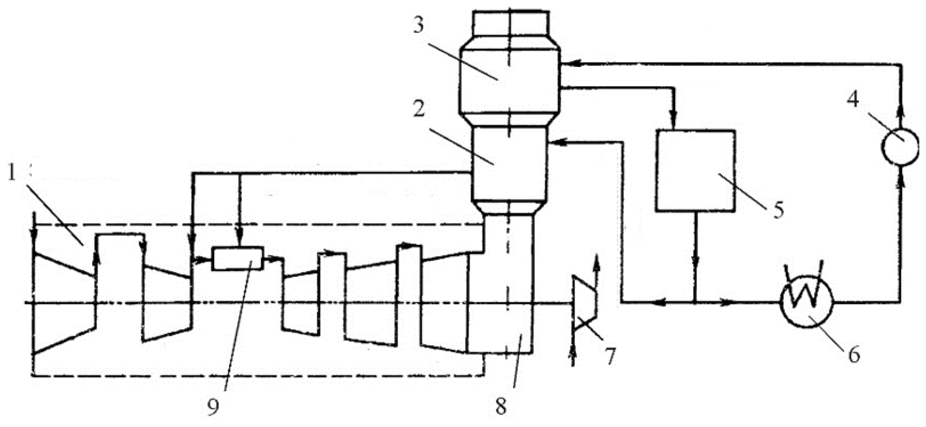
2.2. Determining the Parameters of the “Aquarius” Type Power Plant

To improve the efficiency of gas turbine plants, it is most expedient to increase the thermodynamic parameters of the engine: the pressure ratio and the maximum temperature of the cycle, as well as the addition of a number of new elements that allow us to utilize the heat of waste gases by complicating the thermal scheme of the power plant. This article discusses the possibilities of the technological scheme “Aquarius” for the transfer of existing power plants to hydrogen-containing fuels.
“Aquarius” units with steam injection into the gas turbine engine flow path are characterized by [95]:
  • a large increase in power—up to 80%;
  • minimum values of NOx and CO emissions;
  • low capital costs per unit of installed capacity.
In principle, there are two types of installations operating according to the “Aquarius” cycle—installations with an unconverted (S1) and a converted (S2) gas turbine engine flow path.
S1 type units can be used with high efficiency both in the cogeneration variant—with the transfer of steam to an external consumer, and for obtaining additional electrical energy when steam is supplied to the engine flow path. At the same time, in both cases, high efficiency of the installation is ensured. Such capabilities of S1 type units can allow steam to be used with maximum efficiency to optimize plant operation. Due to the conversion of the flow path of the gas turbine engine, S2 units provide maximum power and efficiency when operating in the steam injection mode.
An additional positive effect of the installations operating according to the “Aquarius” cycle is a significant improvement in the environmental characteristics of the gas turbine engine. Part of the steam is supplied to the combustion zone of the gas turbine engine combustion chamber. In this case, the fuel combustion process is optimized and the level of emissions of nitrogen oxides NOx is significantly reduced.
During the operation of a gas turbine plant according to the well-known STIG cycle, after operation in the engine flow path, together with the exhaust gases, the steam is irrevocably carried away into the atmosphere. In this case, a large amount of boiler water is thrown out. To replenish boiler water, it is necessary to have a special water treatment plant. In some cases, the release of large quantities of gas–steam mixture adversely affects the ecology of nearby areas. The original technology “Aquarius” allows for the separation of the steam from the exhaust gases for reuse in the cycle.
As mentioned above, to raise the efficiency of pure hydrogen combustion in a gas turbine combustor, it is advisable to employ the diffusion principle of combustion with a simultaneous supply of steam to the primary zone of the chamber. This can be implemented in a gas–steam turbine plant of the “Aquarius” type [84,95].
The design scheme of the power plant of the “Aquarius” type is shown in Figure 1. Combustion products are formed during the combustion of pure hydrogen or natural gas–hydrogen mixture and mixing them with superheated steam injected sequentially to the primary zone of the chamber and the dilution zone. Next, the mixture of combustion products and steam enters the compressor’s and generator’s turbines.
In a contact type condenser installed at the exhaust pipe of the waste heat boiler, due to irrigation with water, the gas–steam mixture is cooled to a temperature lower than the dew point, water is precipitated, and condensate is collected. The collected condensate enters the collector, is cleaned of impurities, and is fed back to the waste heat boiler. For water regeneration, the design of a contact condenser was developed. To improve the environmental performance of gas turbine engines, part of the steam supplied to the combustion chamber enters directly into the primary combustion zone (ecological steam supply), while the rest (energy supply) is mixed with gas inside the delusion zone.
A positive effect of the operation of “Aquarius” type plants is their ability to generate an additional amount of fresh water, which is formed as a result of a chemical reaction of hydrocarbon fuel oxidation when it is burned in a combustion chamber. Therefore, the amount of water deposited in the contact condenser is greater than the amount of steam produced by the waste heat boiler.
The main parameters of the installation with steam injection into the combustion chamber were determined according to the thermogasdynamic method, described in detail in our previous work [96]. The developed mathematical model consists of two main modules. The first module is a model of a basic gas turbine engine loaded on an electric generator, which is verified according to the manufacturer’s data under ISO conditions. In the second module, the defining parameters of the base gas turbine engine are recalculated for the conditions of its operation as part of a thermal circuit with a waste heat boiler and a contact condenser, taking into consideration changes in the thermophysical properties of the working medium during steam injection into the combustion chamber.
Comparison of the efficiency of a real power plant of the “Aquarius” type with a gas turbine unit and a steam-water heat recovery circuit of similar parameters showed an increase in the efficiency of the plant by 1.5–2.0%, as well as a significant improvement in weight and size indicators due to the absence of a steam turbine in the installation.

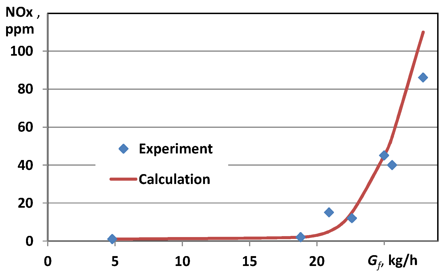
2.3. Verification of Calculated Data

To verify the results of numerical calculations, experimental data from tests of serial combustion chambers of gas turbine engines produced by Gas Turbine Research and Production Complex “Zorja”-“Mashpoekt”, Ukraine, were used [95,97].
The first type of chamber (with premixing of components) is shown in Figure 2. The second type of chamber (with steam injection) is shown in Figure 3.
The main element of the combustion chamber with premixing of components for a 25 MW gas turbine engine is a burner, which includes two special radial–axial swirlers, behind which is located an annular mixing chamber. Gaseous fuel is supplied to the flow part of the swirlers through a series of small diameter holes and is mixed there with the air coming after the compressor. A new technical solution in the design in Figure 2 is the supply of gaseous fuel into the interblade channels of two radial–axial swirlers. The fuel supply to the inner channel ensures the stabilization of the flame front at all engine operating modes, and the fuel supply to the outer channel forms the main air–fuel mixture with a high air excess coefficient to minimize the formation of nitrogen oxides.
The combustion chamber of the “Aquarius” gas–steam power plant with a capacity of 16 MW is a diffusion chamber of a tubular-annular type. A characteristic feature of the combustion chamber is the injection of steam into different parts of the chamber, namely the combustion zone and the dilution zone. This increases the power of the plant and reduces concentrations of nitrogen oxides. An innovative design solution in Figure 3 is the dispersed steam supply along the length of the combustion chamber, as well as the ratio of steam flow rates supplied to these zones to reduce nitrogen oxide emissions.
To verify the mathematical model proposed in Section 2.1, we calculated the emission of NO in the combustor with the premixing of components shown in Figure 2, working on natural gas. The results of the estimations were compared with the data of physical experiments obtained at the experimental combustion chamber [91]. The comparison for different working regimes, which differ in the consumption of gaseous fuel (natural gas) through the nozzle G f , are shown in Figure 4. Good agreement with the data is seen. The correlation coefficient between the results of experiments and numerical calculations is 0.985. A match was also made between the numerical and experimental data on the combustion product’s temperature at twenty-five controlled measuring points for seven working regimes, which showed that the maximum discrepancy in finding the average temperature did not exceed 3%.
Moreover, a match was made between the numerical and experimental parameters for the combustion chamber with steam injection, shown in Figure 5.
The dependences of the nitrogen oxide NO content on the relative power of the gas turbine plant (operating mode) N e were obtained as the results of the numerical calculations and full-scale tests. A satisfactory correlation of the data is also seen. The correlation coefficient between the results of experiments and numerical calculations is 0.986. The deviation of the calculated data from the experimental values for the concentrations of nitrogen oxides does not exceed 5% for the main operating modes of the combustion chamber.
Thus, the use of the proposed continuum-type mathematical model and a simple global kinetic mechanism of fuel combustion make it possible to predict the parameters of gas turbine combustion chambers of various types. This makes it possible to use it to study the characteristics of fuel-burning devices that differ from the prototypes both in design forms and in the type of fuel.
The tasks of the efficiency analysis of the combustion of hydrogen-containing gases and pure hydrogen are (a) to ensure the stable operation of the chamber without a flashback into the zones of preparation of combustible mixtures, (b) to eliminate unstable self-oscillatory modes in the combustion zone, (c) to increase the completeness of fuel combustion (minimize CO emissions during the combustion of hydrogen mixed with natural gas), (d) c to reduce emissions of nitrogen oxides, (e) to reduce the non-uniformity of the temperature field at the exit from the combustion chamber, etc.

3. Results

3.1. Calculation Grids and Initial Parameters

Serial combustion chambers were designed to burn natural gas. In the first stage of creating decarbonized systems, it is planned to transfer them to a natural gas–hydrogen mixture with pure hydrogen and study the possibility of working on pure hydrogen. For this purpose, the corresponding three-dimensional numerical calculations of the flow and the energy characteristics of combustion devices operating on hydrogen and mixtures of natural gas and a certain part of hydrogen were carried out. The finite volume method is used for the calculation.
Before the calculations, three-dimensional geometric models of gas turbine combustion chambers and the corresponding grids were created, which are shown in Figure 6.
The created computational grids are a set of tetrahedral unstructured elements. For the considered sector 22.5° of the combustion chamber with preliminary mixing, the grid consists of 2.7 million elements. For the considered sector 36° of the combustion chamber with steam injection, the grid consists of 3.8 million elements.
Three-dimensional geometries of combustion chambers were built using the SolidWorks program, finite-difference grids—using the ICEM CFD program, and three-dimensional fuel combustion calculations—using the Ansys Fluent program.
The initial parameters of the working media (per one flame tube) for the combustion chamber with preliminary mixing were as follows: air inlet pressure at 1.505 MPa, air flow rate at 3.31 kg/s, air temperature at 759 K, fuel temperature at the inlet at 310 K, its flow rate when operating on hydrogen was 0.02823 kg/s, and with the addition of natural gas it changed according to the change in net calorific value.
The initial parameters of the working media (per one flame tube) for the combustion chamber with steam injection were as follows: air inlet pressure at 2.383 MPa, air flow rate at 2.7515 kg/s, air temperature at 769.3 K, fuel temperature at the inlet at 300 K, its flow rate when operating on hydrogen was 0.03045 kg /s, and with the addition of natural gas it changed according to the change in net calorific value. For all calculations, the flow rate of ecological steam was 0.205 kg/s, and the flow rate of energy steam was 0.25 kg/s at a steam temperature of 700 K.

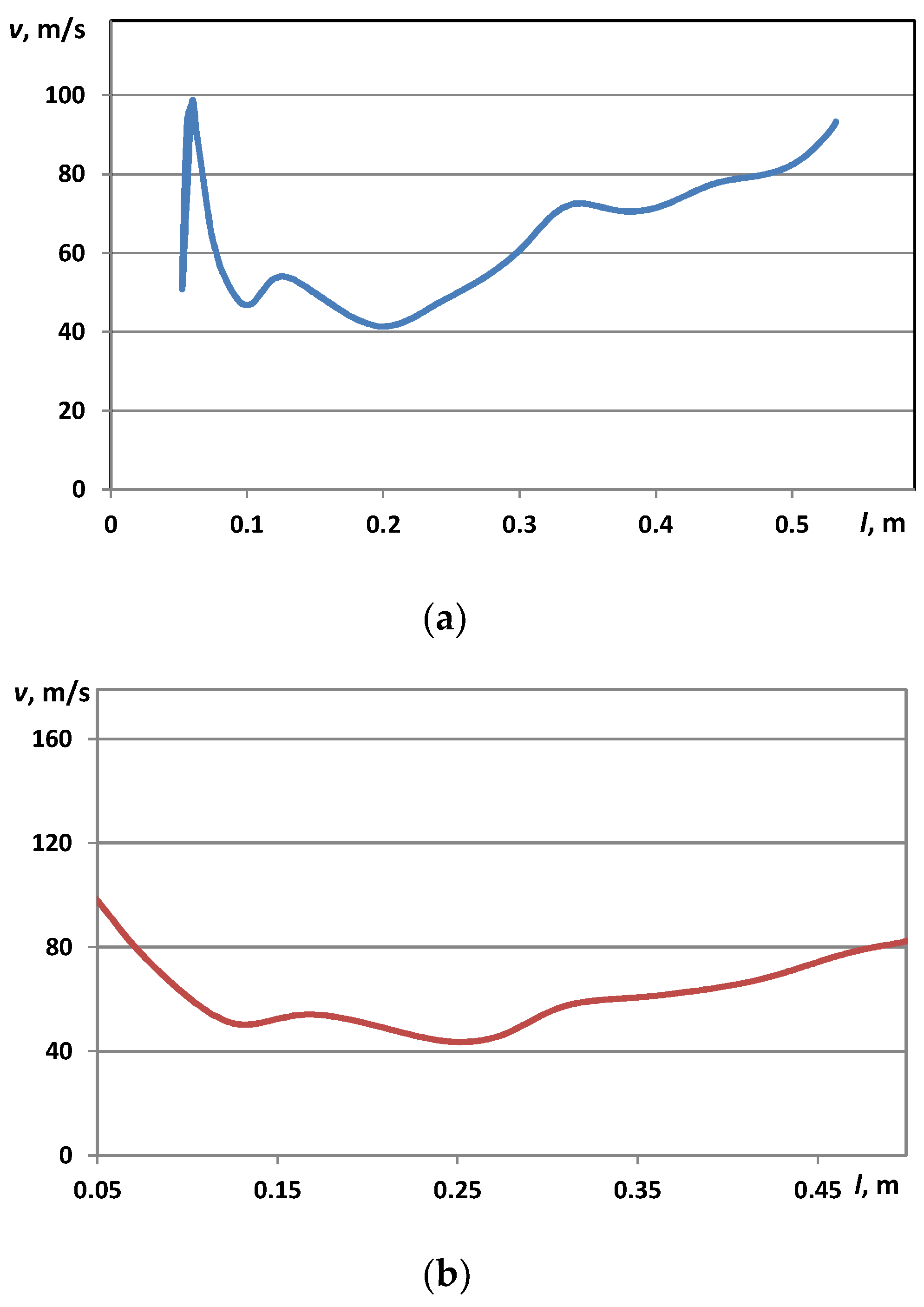
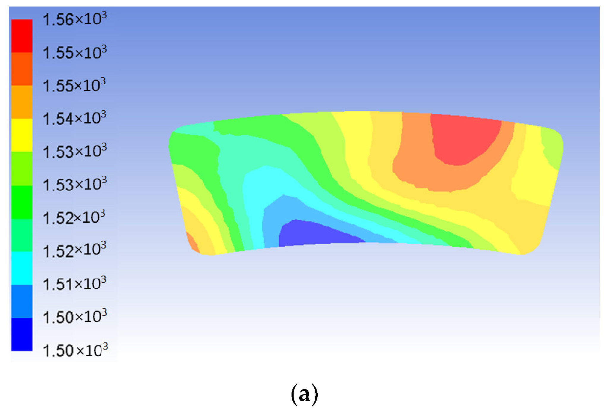
3.2. Aerodynamics and Temperature Distribution

Figure 7 shows the contours of velocity magnitude inside the combustor with the preliminary generation of a hydrogen–air mixture inside the swirlers’ channels and in the combustion chamber with ecological and energy steams feeding (for the “Aquarius” type power installation).
For a premix combustor, fuel is supplied through multiple rows with small holes in the blades of the swirlers (internal and external) into the flow path of these swirlers, where it mixes with air. This mixture is supplied into the combustion chamber’s primary zone, where it is reliably ignited due to the recirculating gases. The distribution of fuel consumption inside the inner and outer swirlers was maintained equal to 0.24 (taking into account the recommendations of [97]). For the combustion chamber with steam injection, the volume of the recirculation zone is smaller; however, the stable ignition and combustion of the fresh mixture are ensured by variable local values of the air excess coefficient.
Figure 8 shows how the magnitude of the velocity of the working fluid changes along the length of the flame tube. It can be seen that the premixed combustion chamber operating on pure hydrogen is characterized by a sharp increase in velocity in the channels of the burner device (in the internal cavity of the radial–axial swirlers), which is due to undesirable flame propagation in these areas. In the chamber with steam injection in the area of the nozzle device, a gradual decrease in the velocity is observed.
Figure 9 shows the contours of the temperature inside the combustion chamber with the preliminary component’s mixing and inside the combustion chamber with steam injection.
It can be seen that in the premixed combustion chamber, when operating on pure hydrogen, there is a flashback from the recirculation zone, which is formed in the axial chamber’s sections, into the inner and outer radial–axial swirlers. This is explained by the high velocity of the turbulent propagation of the hydrogen flame compared with the velocity of the hydrocarbon flame. In the channels of the swirlers, chemical reactions occur between the fuel and the oxidizer, which, during engine operation, will lead to local overheating of the material and emergencies. Thus, without a serious modification of the burner device of such a combustion chamber, it is impossible to ensure the satisfactory operation of the entire gas turbine power complex.
In the diffusion combustion chamber with steam injection, there is no flashback zone. Combustion begins at a certain distance from the fuel injector, and the structure of the flame is determined by the aerodynamics of air, fuel, and steam flows.
The maximum gas temperatures inside the flame tube are slightly higher for the gas turbine combustion chamber with premixing (2560 K) compared with the combustion chamber with steam feeding (2330 K).
Figure 10 shows the change in temperature along the axis of the flame tube. The initial sections of the burner with premixing are characterized by a sharp surge in gas temperature in the cavities of the swirlers. It should be noted that serial flame tubes operating on natural gas do not provide for such conditions, which will lead to the overheating of metal surfaces and their possible destruction when operating on hydrogen.
In the chamber with steam injection, a monotonous increase in gas temperatures along the length of the primary zone is observed, followed by a decrease in temperature due to air in the dilution zone.
Figure 11 shows the contours of temperatures in the outlet section of the considered combustion chambers. It can be seen that for the premixed combustion chamber, the uniformity of the temperature field at the outlet is very high, which indicates a very good quality of mixing of the components. At the outlet from the chamber with steam injection in the central part, a higher temperature core is traced, which is a consequence of insufficient penetration of the energy steam jet into the dilution zone.

3.3. Ecological Parameters of Combustion Chambers

One of the most important characteristics of fuel combustion efficiency is the emissions of toxic components, which are strictly regulated by national and international standards. Therefore, of particular interest are emissions of nitrogen oxides (during the combustion of pure hydrogen), as well as emissions of nitrogen oxides and carbon monoxide (during the joint combustion of natural gas and hydrogen).
For the premixed combustion chamber, several calculations were carried out that made it possible to establish that stable combustion in the primary zone of the chamber without the generation of a flashback occurs at a concentration of hydrogen (by volume), in its mixture with natural gas, of up to 20%. For this hydrogen content, calculations of the formation of nitrogen oxides in the chamber were carried out (Figure 12).
It can be seen that the combustion process begins at the outlet of the axial swirlers and does not propagate into their internal cavities. CO is formed only in the areas closest to the burner; then, it is actively further oxidized to CO2 and has almost zero values at the outlet. The zone of the maximum concentration of nitrogen oxides NO corresponds to the areas with the maximum product temperature, which is explained by the thermal mechanism of the generation of NOx from the air. The average calculated NO concentration at the outlet of the combustion chamber is 18.44 ppm.
The results of calculations of ecological parameters for the combustion chamber of the “Aquarius” type power plant with the injection of overheated steam and operating on pure hydrogen are shown in Figure 13.
Nitrogen oxides are formed in the primary zone of the chamber; however, due to the thermophysical properties of hydrogen and its high penetrating power, relatively high concentrations of nitrogen oxide are also observed in the zone of energy steam injection. The average calculated NO concentration at the outlet of the combustion chamber is 37.97 ppm.
The calculated parameters of the combustion chambers with preliminary component mixing and with steam injection are shown in Table 2.

4. Conclusions and Future Work

The global problem of the decarbonization of energy systems leads to the need to use hydrogen fuels. This provision also applies to gas turbine systems widely used in various fields. In this work, theoretical studies of the possibility of the environmentally friendly combustion of pure hydrogen and mixtures of natural gas with hydrogen in gas turbine combustion chambers were carried out. The following schemes were chosen for analysis: (a) the combustion chamber with the mixing of components in the channels of axial–radial swirlers, and (b) the combustion chamber of the “Aquarius” type power plant with a sequential injection of ecological and energy steam into the combustion chamber.
To determine the characteristics of the combustion of the above fuels, as well as to determine the modes of stable combustion without flashback zones, a corresponding mathematical model of the continuum type was developed. A global chemical scheme for the burning of a mixture of natural gas with hydrogen is recommended, which predicts with sufficient accuracy the emission and aerodynamic parameters of various types of gas turbine combustion chambers. When using this kinetic scheme, the deviation of the calculated data from the experimental values for the concentrations of nitrogen oxides does not exceed 5% for the main operating modes of the combustion chamber; the maximum error in determining the integral temperature at the chamber’s outlet does not exceed 3%.
A mathematical model has been developed for calculating the cycle of a gas–steam turbine plant with steam injection, which made it possible to determine the parameters necessary for designing combustion chambers.
An analysis of the presented results allows us to conclude that the considered scheme of the premixed combustion chamber can only be recommended for operation on mixtures of natural gas with hydrogen, and the amount of hydrogen in the mixture should not exceed 20% (by volume). The calculated concentration of nitric oxide NO at the outlet of the combustion chamber in working regimes without the flashback does not exceed 20 ppm, which complies with international requirements for emissions of toxic components. The calculated concentration of CO at the outlet of the chamber does not exceed 1 ppm, which indicates the complete burnout of hydrocarbon components and the high efficiency of the combustion processes. An increase in the concentration of hydrogen in a mixture with natural gas leads to the appearance of flashback zones and fuel combustion inside the channels of the swirlers.
For the first time, to organize the sustainable combustion of hydrogen in a gas turbine combustion chamber without the presence of flashback zones, an approach was proposed that combined two principles of combustion chamber operation: (a) with a two-stage sequential injection of ecological and energy steam and (b) fuel diffusion burning with a separate supply of components, which was implemented in the “Aquarius” type thermal scheme. Ecological steam is supplied into the primary combustion zone to prevent the formation of nitrogen oxides, and energy steam is injected into the dilution chamber’s zone to increase the specific engine power.
When operating on pure hydrogen for the combustion chamber with steam injection, a flashback zone is not formed, which proves the advantage of a separate supply of components. The average calculated NO concentration at the outlet of the combustion chamber is 37.97 ppm.
Further studies are needed to expand the zone of stable operation of the gas turbine premixed combustor and to eliminate the generation of a flashback with an increase in the concentration of hydrogen.
For gas turbine combustion chambers with a sequential supply of ecological and energy steam, additional theoretical and experimental investigation is needed to optimize the distribution of steam flow rates in terms of minimizing the emission of nitrogen oxides and organizing the efficient cooling of the walls of a combustion chamber operating on pure hydrogen.
The gas turbines with developed combustion chambers can be used in power plants on the base of a simple [98,99] and combined [100,101], as well as regenerative [102], gas turbine cycle. Considering the great influence of ambient air on the efficiency of gas turbines [103,104], the turbine intake air cooling (TIAC) technologies [105] by inlet fogging [106], the application of compression refrigeration machines [107], and the exhaust gas heat recovery chillers of absorption lithium-bromide [108,109] and aqua-ammonia [110,111] types, as well as the simplest in design ejector chillers [17,112] through hybrid dual-coolant cooling [113] in conventional plate fin and tube heat exchangers [114,115] and advanced high efficient Maisotsenko coolers [116,117], such waste heat recovery engine air cooling technologies have found a widespread application in combined heat, cooling, and power plants [118,119], or trigeneration systems [120,121], in various fields of application [20,122,123,124,125]. Therefore, further studies might be focused on the development of gas turbine green technologies combined with TIAC.

Author Contributions

Conceptualization, S.S.; Methodology, S.S. and K.B.; Validation, S.S., K.B. and A.R.; Formal analysis, S.S. and D.C.; Writing—review and editing, S.S. and A.P.; Supervision, M.R.; Project administration, A.P. and M.R. All authors have read and agreed to the published version of the manuscript.

Funding

This research was funded by Ministry of Education and Science of Ukraine, grant number 0123U101952.

Informed Consent Statement

Not applicable.

Data Availability Statement

Not applicable.

Conflicts of Interest

The authors declare no conflict of interest.

References

  1. Yang, Z.; Konovalov, D.; Radchenko, M.; Radchenko, R.; Kobalava, H.; Radchenko, A.; Kornienko, V. Analyzing the efficiency of thermopressor application for combustion engine cyclic air cooling. Energies 2022, 15, 2250. [Google Scholar] [CrossRef]
  2. Wang, K.; Zhao, C.; Cai, Y. Effect of intake air humidification and EGR on combustion and emission characteristics of marine diesel engine at advanced injection timing. J. Therm. Sci. 2021, 30, 1174–1186. [Google Scholar] [CrossRef]
  3. Yang, Z.; Radchenko, M.; Radchenko, A.; Mikielewicz, D.; Radchenko, R. Gas turbine intake air hybrid cooling systems and a new approach to their rational designing. Energies 2022, 15, 1474. [Google Scholar] [CrossRef]
  4. Shukla, A.K.; Singh, O. Thermodynamic investigation of parameters affecting the execution of steam injected cooled gas turbine based combined cycle power plant with vapor absorption inlet air cooling. Appl. Therm. Eng. 2017, 122, 380–388. [Google Scholar] [CrossRef]
  5. Radchenko, R.; Radchenko, N.; Tsoy, A.; Forduy, S.; Zybarev, A.; Kalinichenko, I. Utilizing the heat of gas module by an absorption lithium-bromide chiller with an ejector booster stage. AIP Conf. Proc. 2020, 2285, 030084. [Google Scholar] [CrossRef]
  6. Gluesenkamp, K.; Hwang, Y.; Radermacher, R. High efficiency micro trigeneration systems. Appl. Therm. Eng. 2013, 50, 6. [Google Scholar] [CrossRef]
  7. Popli, S.; Rodgers, P.; Eveloy, V. Gas turbine efficiency enhancement using waste heat powered absorption chillers in the oil and gas industry. Appl. Therm. Eng. 2013, 50, 918–931. [Google Scholar] [CrossRef]
  8. CIMAC. Position Paper Gas Engine Aftertreatment Systems by CIMAC WG 17, Gas Engines. 2017. Available online: https://www.cimac.com/cms/upload/Publication_Press/WG_Publications/CIMAC_WG17_2017_Aug_Position_Paper_Gas_Engine_Aftertreatment_Systems.pdf (accessed on 5 March 2019).
  9. Pardiñas, Á.Á.; Jokiel, M.; Schlemminger, C.; Selvnes, H.; Hafner, A. Modeling of a CO2-Based Integrated Refrigeration System for Supermarkets. Energies 2021, 14, 6926. [Google Scholar] [CrossRef]
  10. Radchenko, A.; Scurtu, I.-C.; Radchenko, M.; Forduy, S.; Zubarev, A. Monitoring the efficiency of cooling air at the inlet of gas engine in integrated energy system. Therm. Sci. 2022, 26, 185–194. [Google Scholar] [CrossRef]
  11. Barreto, D.; Fajardo, J.; Caballero, G.C.; Escorcia, Y.C. Innovative exergy and exergoeconomic analysis of a gas power system with steam injection and air cooling with a compression refrigeration machine. Energy Technol. 2021, 9, 2000993. [Google Scholar] [CrossRef]
  12. Radchenko, M.; Radchenko, A.; Trushliakov, E.; Pavlenko, A.; Radchenko, R. Advanced Method of Variable Refrigerant Flow (VRF) System Design to Forecast on Site Operation–Part 3: Optimal Solutions to Minimize Sizes. Energies 2023, 16, 2417. [Google Scholar] [CrossRef]
  13. Radchenko, M.; Radchenko, A.; Trushliakov, E.; Pavlenko, A.M.; Radchenko, R. Advanced method of variable refrigerant flow (VRF) systems designing to forecast on site operation–Part 1: General approaches and criteria. Energies 2023, 16, 1381. [Google Scholar] [CrossRef]
  14. Radchenko, M.; Radchenko, A.; Trushliakov, E.; Koshlak, H.; Radchenko, R. Advanced method of variable refrigerant flow (VRF) systems designing to forecast on site operation– Part 2: Phenomenological simulation to recuperate refrigeration energy. Energies 2023, 16, 1922. [Google Scholar] [CrossRef]
  15. Cardona, E.; Piacentino, A. A methodology for sizing a trigeneration plant in mediterranean areas. Appl. Therm. Eng. 2003, 23, 15. [Google Scholar] [CrossRef]
  16. Ortiga, J.; Bruno, J.C.; Coronas, A. Operational optimization of a complex trigeneration system connected to a district heating and cooling network. Appl. Therm. Eng. 2013, 50, 1536–1542. [Google Scholar] [CrossRef]
  17. Yang, Z.; Radchenko, R.; Radchenko, M.; Radchenko, A.; Kornienko, V. Cooling potential of ship engine intake air cooling and its realization on the route line. Sustainability 2022, 14, 15058. [Google Scholar] [CrossRef]
  18. Pham, V.V. Advanced Technology Solutions for Treatment and Control Noxious Emission of Large Marine Diesel Engines: A Brief Review. J. Mech. Eng. Res. Dev. 2019, 42, 21–27. [Google Scholar] [CrossRef]
  19. Radchenko, N.; Radchenko, A.; Tsoy, A.; Mikielewicz, D.; Kantor, S.; Tkachenko, V. Improving the efficiency of railway conditioners in actual climatic conditions of operation. AIP Conf. Proc. 2020, 2285, 030072. [Google Scholar]
  20. Radchenko, N.; Trushliakov, E.; Radchenko, A.; Tsoy, A.; Shchesiuk, O. Methods to determine a design cooling capacity of ambient air conditioning systems in climatic conditions of Ukraine and Kazakhstan. AIP Conf. Proc. 2020, 2285, 30074. [Google Scholar] [CrossRef]
  21. One Engine. Three Powerful Results. Trigeneration with Jenbacher Gas Engines. GE Energy. Jenbacher Trigeneration Solutions. 2006. Available online: http://ftp.demec.ufpr.br/disciplinas/TM106/Absorcao.pdf (accessed on 1 November 2022).
  22. Suamir, I.N.; Tassou, S.A. Performance evaluation of integrated trigeneration and CO2 refrigeration systems. Appl. Therm. Eng. 2013, 50, 1487–1495. [Google Scholar] [CrossRef]
  23. Bartnik, R.; Buryn, Z.; Hnydiuk-Stefan, A.; Skomudek, W.; Otawa, A. Thermodynamic and Economic Analysis of Trigeneration System Comprising a Hierarchical Gas-Gas Engine for Production of Electricity, Heat and Cold. Energies 2020, 13, 1006. [Google Scholar] [CrossRef]
  24. Popli, S.; Rodgers, P.; Eveloy, V. Trigeneration scheme for energy efficiency enhancement in a natural gas processing plant through turbine exhaust gas waste heat utilization. Appl. Energy 2012, 93, 623–636. [Google Scholar] [CrossRef]
  25. Maraver, D.; Sin, A.; Royo, J.; Sebastián, F. Assessment of CCHP systems based on biomass combustion for small-scale applications through a review of the technology and analysis of energy efficiency parameters. Appl. Energy 2013, 102, 1303–1313. [Google Scholar] [CrossRef]
  26. Khaliq, A.; Dincer, I.; Sharma, P.B. Development and analysis of industrial waste heat based trigeneration for combined generation of power heat and cold. J. Energy Inst. 2010, 83, 79–85. [Google Scholar] [CrossRef]
  27. Radchenko, A.; Radchenko, N.; Tsoy, A.; Portnoi, B.; Kantor, S. Increasing the efficiency of gas turbine inlet air cooling in actual climatic conditions of Kazakhstan and Ukraine. AIP Conf. Proc. 2020, 2285, 030071. [Google Scholar] [CrossRef]
  28. Chacartegui, R.; Jiménez-Espadafor, F.; Sánchez, D.; Sánchez, T. Analysis of combustion turbine inlet air cooling systems applied to an operating cogeneration power plant. Energy Convers. Manag. 2008, 49, 2130–2141. [Google Scholar] [CrossRef]
  29. Mito, M.T.; Teamah, M.A.; El-Maghlany, W.M.; Shehata, A.I. Utilizing the scavenge air cooling in improving the performance of marine diesel engine waste heat recovery systems. Energy 2018, 142, 264–276. [Google Scholar] [CrossRef]
  30. Cipollone, R.; Di Battista, D.; Vittorini, D. Experimental assessment of engine charge air cooling by a refrigeration unit. Energy Procedia 2017, 126, 1067–1074. [Google Scholar] [CrossRef]
  31. Ibrahim, T.K.; Rahman, M.M.; Abdalla, A.N. Study on the effective parameter of gas turbine model with intercooled compression process. Sci. Res. Essays 2010, 5, 3760–3770. [Google Scholar]
  32. Konovalov, D.; Radchenko, M.; Kobalava, H.; Kornienko, V.; Maksymov, V.; Radchenko, A.; Radchenko, R. Research of characteristics of the flow part of an aerothermopressor for gas turbine intercooling air. Proc. Inst. Mech. Eng. Part A J. Power Energy 2021, 236, 634–646. [Google Scholar] [CrossRef]
  33. Yang, Z.; Zhang, D.; Caglayan, O.; Jenkinson, I.; Bonsall, S.; Wang, J.; Huang, M.; Yan, X. Selection of techniques for reducing shipping NOx and SOx emissions. Transp. Res. Part D Transp. Environ. 2012, 17, 478–486. [Google Scholar] [CrossRef]
  34. Manzela, A.A.; Hanriot, S.M.; Cabezas-Gómez, L.; Sodré, J.R. Using engine exhaust gas as energy source for an absorption refrigeration system. Appl. Energy 2010, 87, 1141–1148. [Google Scholar] [CrossRef]
  35. Wang, F.; Guo, H. Design of mixed scrubbing and desulfurization system for a marine engine. IOP Conf. Ser. Mater. Sci. Eng. 2019, 472, 012098. [Google Scholar] [CrossRef]
  36. Hua, Y.; Wang, Z.; Li, R.; Liu, S.; Zhao, Y.; Qu, L.; Mei, D.; Lv, H. Experimental study on morphology, nanostructure and oxidation reactivity of particles in diesel engine with exhaust gas recirculation (EGR) burned with different alternative fuels. Energy 2022, 261, 125249. [Google Scholar] [CrossRef]
  37. Yang, Z.; Kornienko, V.; Radchenko, M.; Radchenko, A.; Radchenko, R. Research of Exhaust Gas Boiler Heat Exchange Surfaces with Reduced Corrosion when Water-fuel Emulsion Combustion. Sustainability 2022, 14, 11927. [Google Scholar] [CrossRef]
  38. Kornienko, V.; Radchenko, R.; Bohdal, T.; Radchenko, M.; Andreev, A. Thermal characteristics of the wet pollution layer on condensing heating surfaces of exhaust gas boilers. In Advances in Design, Simulation and Manufacturing IV; DSMIE 2021. Lecture Notes in Mechanical Engineering; Ivanov, V., Pavlenko, I., Liaposhchenko, O., Machado, J., Edl, M., Eds.; Springer: Cham, Switzerland, 2021; pp. 339–348. [Google Scholar] [CrossRef]
  39. Shu, G.; Liang, Y.; Wei, H.; Tian, H.; Zhao, J.; Liu, L. A review of waste heat recovery on two-stroke IC engine aboard ships. Renew. Sustain. Energy Rev. 2013, 19, 385–401. [Google Scholar] [CrossRef]
  40. Valluri, S.; Kawatra, S.K. Simultaneous removal of CO2, NOx and SOx using single stage absorption column. J. Environ. Sci. 2021, 103, 279–287. [Google Scholar] [CrossRef] [PubMed]
  41. Yang, Z.; Kornienko, V.; Radchenko, M.; Radchenko, A.; Radchenko, R.; Pavlenko, A. Capture of pollutants from exhaust gases by low-temperature heating surfaces. Energies 2022, 15, 120. [Google Scholar] [CrossRef]
  42. Deng, J.; Wang, X.; Wei, Z.; Wang, L.; Wang, C.; Chen, Z. A review of NOx and SOx emission reduction technologies for marine diesel engines and the potential evaluation of liquefied natural gas fueled vessels. Sci. Total Environ. 2021, 766, 144319. [Google Scholar] [CrossRef]
  43. Chen, D.; Wang, T.; Yang, T.; Li, G.; Chen, Y.; Qiao, T. Effects of EGR combined with DOC on emission characteristics of a two-stage injected Fischer-Tropsch diesel/methanol dual-fuel engine. Fuel 2022, 3291, 125451. [Google Scholar] [CrossRef]
  44. Yu, Z.; Shevchenko, S.; Radchenko, M.; Shevchenko, O.; Radchenko, A. Methodology of Designing Sealing Systems for Highly Loaded Rotary Machines. Sustainability 2022, 14, 15828. [Google Scholar] [CrossRef]
  45. Muszyñski, T.; Mikielewicz, D. Comparison of heat transfer characteristics in surface cooling with boiling microjets of water, ethanol and HFE7100. Appl. Therm. Eng. 2016, 93, 1403–1409. [Google Scholar] [CrossRef]
  46. Konur, O.; Saatcioglu, O.Y.; Korkmaz, S.A.; Erdogan, A.; Colpan, C.O. Heat exchanger network design of an organic Rankine cycle integrated waste heat recovery system of a marine vessel using pinch point analysis. Int. J. Energy Res. 2020, 44, 12312–12328. [Google Scholar] [CrossRef]
  47. Pavlenko, A.M.; Koshlak, H. Application of Thermal and Cavitation Effects for Heat and Mass Transfer Process Intensification in Multicomponent Liquid Media. Energies 2021, 14, 7996. [Google Scholar] [CrossRef]
  48. Wajs, J.; Mikielewicz, D.; Jakubowska, B. Performance of the domestic micro ORC equipped with the shell-and-tube condenser with minichannels. Energy 2018, 157, 853–861. [Google Scholar] [CrossRef]
  49. Mikielewicz, D.; Klugmann, M.; Wajs, J. Flow boiling intensification in minichannels by means of mechanical flow turbulising inserts. Int. J. Therm. Sci. 2013, 65, 79–91. [Google Scholar] [CrossRef]
  50. Kruzel, M.; Bohdal, T.; Dutkowski, K.; Radchenko, M. The Effect of Microencapsulated PCM Slurry Coolant on the Efficiency of a Shell and Tube Heat Exchanger. Energies 2022, 15, 5142. [Google Scholar] [CrossRef]
  51. Radchenko, M.; Radchenko, A.; Mikielewicz, D.; Radchenko, R.; Andreev, A. A novel degree-hour method for rational design loading. Proc. Inst. Mech. Eng. Part A J. Power Energy 2022. [Google Scholar] [CrossRef]
  52. Dutkowski, K.; Kruzel, M. Microencapsulated PCM slurries’ dynamic viscosity experimental investigation and temperature dependent prediction model. Int. J. Heat Mass Transf. 2019, 145, 118741. [Google Scholar] [CrossRef]
  53. Radchenko, A.; Radchenko, M.; Mikielewicz, D.; Pavlenko, A.; Radchenko, R.; Forduy, S. Energy saving in trigeneration plant for food industries. Energies 2022, 15, 1163. [Google Scholar] [CrossRef]
  54. Radchenko, A.; Radchenko, M.; Koshlak, H.; Radchenko, R.; Forduy, S. Enhancing the efficiency of integrated energy system by redistribution of heat based of monitoring data. Energies 2022, 15, 8774. [Google Scholar] [CrossRef]
  55. Ullah, I.; Hussain, I.; Rehman, K.; Wróblewski, P.; Lewicki, W.; Kavin, B.P. Exploiting the Moth–Flame Optimization Algorithm for Optimal Load Management of the University Campus: A Viable Approach in the Academia Sector. Energies 2022, 15, 3741. [Google Scholar] [CrossRef]
  56. Andi, B.; Venkatesan, J.; Suresh, S.; Mariappan, V. Experimental Analysis of Triple Fluid Vapour Absorption Refrigeration System Driven by Electrical Energy and Engine Waste Heat. Therm. Sci. 2019, 23, 2995–3001. [Google Scholar]
  57. Abusaa, G.; Issa, K. Performance Improvements of Power Generation Using Waste Heat Hybrid Cooling Plant. Kingdom Trigeneration Summit. 2013, p. 24. Available online: http://www.adcenergysystems.com/images/Downloads/Tri-Gen%202013%Performance%20Improvements%20of%20Power%20Generation%20–%20K.Issa,%20ADC.pdf (accessed on 20 February 2020).
  58. Carvalho, M.; Lozano, M.A.; Serra, L.M. Multicriteria synthesis of trigeneration systems considering economic and environmental aspects. Appl. Energy 2012, 91, 245–254. [Google Scholar] [CrossRef]
  59. Kim, M.; Oh, J.; Lee, C. Study on combustion and emission characteristics of marine diesel oil and water-in-oil emulsified marine diesel oil. Energies 2018, 11, 1830. [Google Scholar] [CrossRef]
  60. Kim, M.C.; Lee, C.S. It’s effects for engine emission of water/oil emulsified fuel. Anal. Sci. Technol. 2008, 21, 156–166. [Google Scholar]
  61. S&P Global Commodity Insights. Forecasting How Today’s Energy Mix Evolves into the Energy Mix of Tomorrow. Available online: https://www.spglobal.com/commodityinsights/en/energy-transition-service (accessed on 8 April 2023).
  62. Klyuev, R.V.; Gavrina, O.A.; Madaeva, M.Z. Benefits of solar power plants for energy supply to consumers in mountain territories. In Proceedings of the 2019 International Multi-Conference on Industrial Engineering and Modern Technologies, FarEastCon 2019, Vladivostok, Russia, 1–4 October 2019. [Google Scholar]
  63. Hannan, M.A.; Al-Shetwi, A.Q.; Mollik, M.S.; Ker, P.J.; Mannan, M.; Mansor, M.; Al-Masri, H.M.K.; Mahlia, T.M.I. Wind Energy Conversions, Controls, and Applications: A Review for Sustainable Technologies and Directions. Sustainability 2023, 15, 3986. [Google Scholar] [CrossRef]
  64. Igwe, C.I. Geothermal Energy: A Review. Int. J. Eng. Res. Technol. (IJERT) 2021, 10, 655–661. [Google Scholar]
  65. Sarker, A.K.; Azad, A.K.; Rasul, M.G.; Doppalapudi, A.T. Prospect of Green Hydrogen Generation from Hybrid Renewable Energy Sources: A Review. Energies 2023, 16, 1556. [Google Scholar] [CrossRef]
  66. Hydrogen Gas Turbines. The Path towards a Zero-Carbon Gas Turbine. ETN Global Report. Available online: https://etn.global/wp-content/uploads/2020/02/ETN-Hydrogen-Gas-Turbines-report.pdf (accessed on 10 February 2022).
  67. Nose, M.; Kawakami, T.; Araki, H.; Senba, N.; Tanimura, S. Hydrogen-Fired Gas Turbine Targeting Realization of CO2-Free Society. Mitsubishi Heavy Industries Technical Review. Available online: https://www.mhi.co.jp/technology/review/pdf/e554/e554180.pdf (accessed on 6 February 2022).
  68. Beital, J.; Talibi, M.; Sadasivuni, S.; Balachandran, R. Thermoacoustic Instability Considerations for High Hydrogen Combustion in Lean Premixed Gas Turbine Combustors: A Review. Hydrogen 2021, 2, 33–57. [Google Scholar] [CrossRef]
  69. Tekin, N.; Ashikaga, M.; Horikawa, A.; Funke, H. Enhancement of Fuel Flexibility of Industrial Gas Turbines by Development of Innovative Hydrogen Combustion Systems. Gas for Energy. Available online: https://www.researchgate.net/publication/332290711_Enhancement_of_fuel_flexibility_of_industrial_gas_turbines_by_development_of_innovative_hydrogen_combustion_systems (accessed on 5 February 2022).
  70. Soroka, B.S.; Pyanykh, K.E.; Zgursky, V.O.; Gorupa, V.V.; Kudryavtsev, V.S. Energy and environmental characteristics of household gas appliances using methane-hydrogen mixture as a fuel gas. Oil Gas Ind. Ukr. 2020, 6, 3–13. (In Ukrainian) [Google Scholar]
  71. Amaduzzi, R.; Ferrarotti, M.; Parente, A. Strategies for Hydrogen-Enriched Methane Flameless Combustion in a Quasi-Industrial Furnace. Frontiers in Energy Research. Available online: https://www.frontiersin.org/articles/10.3389/fenrg.2020.590300/full (accessed on 5 February 2022).
  72. Cappellettia, A.; Martellia, F.; Bianchib, E.; Trifonic, E. Numerical redesign of 100 kW MGT combustor for 100% H2 fueling. Energy Procedia 2014, 45, 1412–1421. [Google Scholar] [CrossRef]
  73. Barati, S.; De Santoli, L.; Lo Basso, G. Modeling and Analysis of a Micro Gas Turbine Fuelled with Hydrogen and Natural Gas Blends. E3S Web Conf. 2021, 312, 1–13. [Google Scholar]
  74. Ayed, A.H.; Kusterer, K.; Funke, H.H.W.; Keinz, J.; Bohn, D. CFD based exploration of the dry-low-NOx hydrogen micromix combustion technology at increased energy densities. Propuls. Power Res. 2017, 6, 15–24. [Google Scholar] [CrossRef]
  75. Ayed, A.H.; Kusterer, K.; Funke, H.H.W.; Keinz, J. CFD Based Improvement of the DLN Hydrogen Micromix Combustion Technology at Increased Energy Densities. Am. Sci. Res. J. Eng. Technol. Sci. (ASRJETS) 2016, 26, 290–303. [Google Scholar]
  76. Vilag, V.; Vilag, J.; Carlanescu, R.; Mangra, A.; Florean, F. CFD Application for Gas Turbine Combustion Simulations. In Computational Fluid Dynamics Simulations; Ji, G., Zhu, J., Eds.; IntechOpen: London, UK, 2019; Available online: https://www.intechopen.com/chapters/69672 (accessed on 7 February 2022).
  77. Syred, N.; Abdulsada, M.; Griffiths, A.; O’Doherty, T.; Bowen, P. The effect of hydrogen containing fuel blends upon flashback in swirl burners. Appl. Energy 2012, 89, 106–110. [Google Scholar] [CrossRef]
  78. Gobbato, P.; Masi, M.; Toffolo, A.; Lazzaretto, A. Numerical simulation of a hydrogen fuelled gas turbine combustor. Int. J. Hydrogen Energy 2011, 36, 7993–8002. [Google Scholar] [CrossRef]
  79. Attia, M.E.H.; Khechekhouche, A.; Driss, Z. Numerical Simulation of Methane-Hydrogen Combustion in the Air: Influence on Combustion Parameters. Indian J. Sci. Technol. 2018, 11, 1–8. [Google Scholar] [CrossRef]
  80. Reza, S.; Rahimi, M.; Khoshhal, A.; Alsairafi, A.A. CFD Study on Hydrogen-Air Premixed Combustion in a Micro Scale Chamber. Iran. J. Chem. Chem. Eng. 2010, 29, 161–172. [Google Scholar]
  81. Göke, S.; Füri, M.; Bourque, G.; Bobusch, B.; Göckeler, K.; Krüger, O.; Schimek, S.; Terhaar, S.; Paschereit, C.O. Influence of steam dilution on the combustion of natural gas and hydrogen in premixed and rich-quench-lean combustors. Fuel Process. Technol. 2013, 107, 14–22. [Google Scholar] [CrossRef]
  82. Cheng, D.Y.; Nelson, A.L.C. The chronological development of the Cheng cycle steam injected gas turbine during the past 25 years. In Proceedings of the ASME Turbo Expo 2002, Amsterdam, The Netherlands, 3–6 June 2002; GT-2002–30119 2002. pp. 1–8. [Google Scholar]
  83. Movchan, S.N.; Romanov, V.V.; Chobenko, V.N.; Shevtsov, A.P. Contact Steam-and-Gas Turbine Units of the “AQUARIUS” Type: The Present Status and Future Prospects. In Proceedings of the ASME Turbo Expo 2009: Power for Land, Sea, and Air, Orlando, FL, USA, 8–12 June 2009; pp. 1–7. [Google Scholar]
  84. Serbin, S.; Burunsuz, K.; Chen, D. Investigation of the Characteristics of a Gas Turbine Combustion Chamber with Steam Injection Operating on Hydrogen-Containing Mixtures and Hydrogen. Int. J. Chem. Eng. 2022, 2022, 1–12. [Google Scholar] [CrossRef]
  85. Launder, B.E.; Spalding, D.B. Lectures in Mathematical Models of Turbulence; Academic Press: London, UK, 1972. [Google Scholar]
  86. Serbin, S.I.; Matveev, I.B.; Mostipanenko, G.B. Plasma-Assisted Reforming of Natural Gas for GTL: Part II—Modeling of the Methane-Oxygen Reformer. IEEE Trans. Plasma Sci. 2015, 43, 3964–3968. [Google Scholar] [CrossRef]
  87. Serbin, S.I.; Kozlovskyi, A.V.; Burunsuz, K.S. Investigations of non-stationary processes in low emissive gas turbine combustor with plasma assistance. IEEE Trans. Plasma Sci. 2016, 44, 2960–2964. [Google Scholar] [CrossRef]
  88. Yakhot, V.; Orszag, S.A. Renormalization Group Analysis of Turbulence: I. Basic Theory. J. Sci. Comput. 1986, 1, 1–51. [Google Scholar] [CrossRef]
  89. Magnussen, B.F.; Hjertager, B.H. On mathematical models of turbulent combustion with special emphasis on soot formation and combustion. Combust. Inst. 1977, 16, 719–729. [Google Scholar] [CrossRef]
  90. Magnussen, B.F. On the Structure of Turbulence and a Generalized Eddy Dissipation Concept for Chemical Reaction in Turbulent Flow. In Proceedings of the 19th Aerospace Sciences Meeting, St. Louis, MO, USA, 12–15 January 1981; pp. 1–7. [Google Scholar]
  91. Gran, I.R.; Magnussen, B.F. A numerical study of a bluff-body stabilized diffusion flame. Part 2. Influence of combustion modeling and finite-rate chemistry. Combust. Sci. Technol. 1996, 119, 191–217. [Google Scholar] [CrossRef]
  92. Meloni, R. Pollutant Emission Validation of a Heavy-Duty Gas Turbine Burner by CFD Modeling. Machines 2013, 2, 81–97. [Google Scholar] [CrossRef]
  93. ANSYS. ANSYS Fluent Theory Guide; ANSYS, Inc.: Canonsburg, PA, USA, 2013; pp. 1–780. [Google Scholar]
  94. Serbin, S.I. Features of liquid-fuel plasma-chemical gasification for diesel engines. IEEE Trans. Plasma Sci. 2006, 34, 2488–2496. [Google Scholar] [CrossRef]
  95. Bondin, Y.N.; Krivutsa, V.A.; Movchan, S.N.; Romanov, V.I.; Kolomeev, V.N.; Shevtsov, A.P. Operation experience of a gas turbine unit GPU-16K with steam injection. Gas Turbine Technol. 2004, 5, 18–20. (In Russian) [Google Scholar]
  96. Serbin, S.; Washchilenko, N.; Dzida, M.; Kowalski, J. Parametric analysis of the efficiency of the combined gas-steam turbine unit of a hybrid cycle for the FPSO vessel. Polish Marit. Res. 2021, 28, 122–132. [Google Scholar] [CrossRef]
  97. Serbin, S.; Burunsuz, K.; Chen, D.; Kowalski, J. Investigation of the Characteristics of a Low-Emission Gas Turbine Combustion Chamber Operating on a Mixture of Natural Gas and Hydrogen. Pol. Marit. Res. 2022, 29, 64–76. [Google Scholar] [CrossRef]
  98. Shukla, A.K.; Sharma, A.; Sharma, M.; Mishra, S. Performance Improvement of Simple Gas Turbine Cycle with Vapor Compression Inlet Air Cooling. Mater. Today Proc. 2018, 5, 19172–19180. [Google Scholar] [CrossRef]
  99. Patel, V.R.; Chaudhari, K.V.; Pathak, B.C.; Shekh, A.A. Evaluation of output and heat rate of the simple cycle gas turbine during the base load condition. Int. J. Adv. Res. Eng. Sci. Technol. 2015, 2, 2394–2444. [Google Scholar]
  100. Radchenko, M.; Portnoi, B.; Kantor, S.; Forduy, S.; Konovalov, D. Rational Thermal Loading the Engine Inlet Air Chilling Complex with Cooling Towers. In Advanced Manufacturing Processes II: Selected Papers from the 2nd Grabchenko’s International Conference on Advanced Manufacturing Processes (InterPartner-2020), Odessa, Ukraine, 8–11 September 2020; Lecture Notes in Mechanical, Engineering; Tonkonogyi, V., Ed.; Springer International Publishing: New York, NY, USA, 2021; pp. 724–733. [Google Scholar]
  101. Zhang, T.; Liu, Z.; Hao, H.; Chang, L.J. Application Research of Intake-Air Cooling Technologies in Gas-Steam Combined Cycle Power Plants in China. Power Energy Eng. 2014, 2, 304–311. Available online: https://www.scirp.org/journal/paperinformation.aspx?paperid=44921 (accessed on 5 December 2021). [CrossRef]
  102. Mahmoudi, S.M.; Zare, V.; Ranjbar, F.; Farshi, L.J. Energy and exergy analysis of simple and regenerative gas turbines inlet air cooling using absorption refrigeration. Appl. Sci. 2009, 9, 2399–2407. [Google Scholar] [CrossRef]
  103. Şen, G.; Nil, M.; Mamur, H.; Doğan, H.; Karamolla, M.; Karaçor, M.; Kuyucuoğlu, F.; Yörükeren, N.; Bhuiyan, M.R.A. The effect of ambient temperature on electric power generation in natural gas combined cycle power plant—A case study. Energy Rep. 2018, 4, 682–690. [Google Scholar] [CrossRef]
  104. Tiwari, A.K.; Hasan, M.M.; Islam, M. Effect of ambient temperature on the performance of a combined cycle power plant. Trans. Can. Soc. Mech. Eng. 2013, 37, 1177–1188. [Google Scholar] [CrossRef]
  105. Yang, Z.; Korobko, V.; Radchenko, M.; Radchenko, R. Improving thermoacoustic low temperature heat recovery systems. Sustainability 2022, 14, 12306. [Google Scholar] [CrossRef]
  106. Chaker, M.; Meher-Homji, C.B.; Mee, T.; Nicolson, A. Inlet fogging of gas turbine engines-detailed climatic analysis of gas turbine evaporative cooling potential. In Proceedings of the ASME International Gas Turbine and Aeroengine Conference, New Orleans, LA, USA, 4–7 June 2001. ASME Paper 2001-GT-526. [Google Scholar]
  107. Yu, Z.; Løvås, T.; Konovalov, D.; Trushliakov, E.; Radchenko, M.; Kobalava, H.; Radchenko, R.; Radchenko, A. Investigation of thermopressor with incomplete evaporation for gas turbine intercooling systems. Energies 2023, 16, 20. [Google Scholar] [CrossRef]
  108. Wan, X.; Chua, H. Absorption Cooling: A review of Lithium Bromide-Water chiller technologies. Recent Pat. Mech. Eng. 2009, 2, 193–213. [Google Scholar]
  109. Trushliakov, E.; Radchenko, M.; Radchenko, A.; Kantor, S.; Zongming, Y. Statistical Approach to Improve the Efficiency of Air Conditioning System Performance in Changeable Climatic Conditions. In Proceedings of the 5th International Conference on Systems and Informatics, ICSAI 2018, Nanjing, China, 10–12 November 2018; pp. 256–260. [Google Scholar]
  110. Al-Tahaineh, H.A. Cooling of compressor air inlet of a gas turbine power plant using ammonia-water vapor absorption system. Int. J. Energy Eng. 2013, 3, 267–271. [Google Scholar]
  111. Bortmany, J.N. Assesstment of aqua-ammonia refrigeration for pre-cooling gas turbine inlet air. In Proceedings of the ASME TURBO EXPO 2002, Amsterdam, The Netherlands, 3–6 June 2002. Paper GT-2002–30657, 12p. [Google Scholar]
  112. Kornienko, V.; Radchenko, R.; Radchenko, M.; Radchenko, A.; Pavlenko, A.; Konovalov, D. Cooling cyclic air of marine engine with water-fuel emulsion combustion by exhaust heat recovery chiller. Energies 2022, 15, 248. [Google Scholar] [CrossRef]
  113. Kwon, H.M.; Kim, T.S.; Sohn, J.L. Performance improvement of gas turbine combined cycle power plant by dual cooling of the inlet air and turbine coolant using an absorption chiller. Energy 2018, 163, 1050–1061. [Google Scholar] [CrossRef]
  114. Korze’n, A.; Taler, D. Modeling of transient response of a plate fin and tube heat exchanger. Int. J. Therm. Sci. 2015, 92, 188–198. [Google Scholar] [CrossRef]
  115. Taler, D. Mathematical modeling and control of plate fin and tube heat exchangers. Energy Convers. Manag. 2015, 96, 452–462. [Google Scholar] [CrossRef]
  116. Dizaji, H.S.; Hu, E.J.; Chen, L.; Pourhedayat, S. Using novel integrated Maisotsenko cooler and absorption chiller for cooling of gas turbine inlet air. Energy Convers. Manag. 2019, 195, 1067–1078. [Google Scholar] [CrossRef]
  117. Zhu, G.; Chow, T.-T.; Lee, C.-K. Performance analysis of biogas-fueled Maisotsenko combustion turbine cycle. Appl. Therm. Eng. 2021, 195, 117247. [Google Scholar] [CrossRef]
  118. Lozano, M.; Ramos, J.C.; Serra, L.M. Cost Optimization of the Design of CHCP (Combined Heat, Cooling and Power) Systems under Legal Constraints. Energy 2010, 35, 794–805. [Google Scholar] [CrossRef]
  119. Department of Military and Veterans Affairs. Combined Heat and Power Project Feasibility Study; CHA Project Number: 33710. Prepared by CHA, 26 April 2018; Vineland Veterans Memorial Home: Vineland, NJ, USA, 2018; 412p. [Google Scholar]
  120. Rodriguez-Aumente, P.A.; Rodriguez-Hidalgo, M.C.; Nogueira, J.I.; Lecuona, A.; Venegas, M.C. District heating and cooling for business buildings in Madrid. Appl. Therm. Eng. 2013, 50, 1496–1503. [Google Scholar] [CrossRef]
  121. Rouse, G.; Czachorski, M.; Bishop, P.; Patel, J. GTI Integrated Energy System for Buildings. Modular System Prototype; GTI Project report 15357/65118; Gas Technology Institute (GTI): Des Plaines IL, USA, 2006; 495p. [Google Scholar]
  122. Chua, K.J.; Yang, W.M.; Wong, T.Z.; Ho, C. Integrating renewable energy technologies to support building trigeneration—A multi-criteria analysis. Renew. Energy 2012, 41, 358–367. [Google Scholar] [CrossRef]
  123. Arteconi, A.; Brandoni, C.; Polonara, F. Distributed generation and trigeneration: Energy saving opportunities in Italian supermarket sector. Appl. Therm. Eng. 2009, 29, 1735–1743. [Google Scholar] [CrossRef]
  124. Freschi, F.; Giaccone, L.; Lazzeroni, P.; Repetto, M. Economic and environmental analysis of a trigeneration system for food-industry: A case study. Appl. Energy 2013, 107, 157–172. [Google Scholar] [CrossRef]
  125. Bassols, J.; Kuckelkorn, B.; Langrek, J.; Schneider, R.; Veelken, H. Trigeneration in the food industry. Appl. Therm. Eng. 2002, 22, 595–602. [Google Scholar] [CrossRef]
Figure 1. The scheme of the “Aquarius” type power plant: 1—gas turbine engine; 2—waste heat boiler; 3—steam-gas condenser; 4—electric pump; 5—condensate collector; 6—cooler; 7—power consumer; 8—gas outlet; 9—gas turbine combustion chamber.
Energies 16 03618 g001
Figure 2. Combustion chamber with premixing of components: 1, 2—fuel collectors; 3, 4—fuel supply lines; 5—casing of compressor; 6—burner; 7—spacer; 8—frame; 9—flame tube; 10—turbine casing; 11—diffuser; 12—housing.
Energies 16 03618 g002
Figure 3. Combustion chamber of the “Aquarius” gas–steam power plant with steam injection: 1—ecological steam supply; 2—energy steam supply; 3—fuel supply; 4—air inlet.
Energies 16 03618 g003
Figure 4. Concentrations of NOx at the outlet of the combustion chamber with preliminary mixing of the components.
Energies 16 03618 g004
Figure 5. Computed and experimental concentrations of nitrogen oxides in the combustion chamber with steam injection.
Energies 16 03618 g005
Figure 6. Calculation grids of the combustion chamber with preliminary component mixing (a) and with steam injection (b).
Energies 16 03618 g006
Figure 7. Contours of velocity magnitude, m/s, inside the combustion chamber with preliminary component mixing (a) and with steam injection (b).
Energies 16 03618 g007
Figure 8. Velocity magnitude distribution along the flame tube length for the combustion chamber with preliminary component mixing (a) and with steam injection (b).
Energies 16 03618 g008
Figure 9. Contours of temperature, K, inside the volume of combustion chamber with preliminary component mixing (a) and with steam injection (b).
Energies 16 03618 g009
Figure 10. Temperature distribution along the flame tube length for the combustion chamber with preliminary component mixing (a) and with steam injection (b).
Energies 16 03618 g010
Figure 11. Contours of temperature, K, at the outlet of the combustion chamber with preliminary component mixing (a) and with steam injection (b).
Energies 16 03618 g011aEnergies 16 03618 g011b
Figure 12. Contours of temperature (a), mass fraction of CO (b), mass fraction of NO (c) in longitudinal section, and mass fraction of NO at the outlet (d) for the premixed combustion chamber at 20% H2 (by volume).
Energies 16 03618 g012
Figure 13. Contours of mass fraction of NO in longitudinal section (a) and at the outlet (b) for combustion chamber with steam injection.
Energies 16 03618 g013
Table 1. Rate constants of chemical reactions.
ReactionAE, J/kg MoleβOrder of Reaction
CH4 + 1.5 O2 → CO + 2 H2O4.64 × 1091.17 × 108−0.062CH40.5O21.066
CO + 0.5 O2 → CO23.97 × 10117.68 × 1070.215O21.756CO1.258
CO2 → CO + 0.5 O26.02 × 1051.31 × 108−0.108CO21.357
H2 + 0.5 O2 → H2O9.87 × 1083.1× 1070H21.0O21.0
Table 2. Calculation results.
ParametersWith Preliminary MixingWith Steam Injection
Air pressure at the inlet, MPa1.502.38
Air flow rate per flame tube, kg/s3.312.75
Air temperature, K759769
Fuel temperature, K310300
Composition: hydrogen/natural gas (by volume)20/80100/0
NO content at the outlet, ppm18.4037.97
CO content at the outlet, ppm0.860.0
Disclaimer/Publisher’s Note: The statements, opinions and data contained in all publications are solely those of the individual author(s) and contributor(s) and not of MDPI and/or the editor(s). MDPI and/or the editor(s) disclaim responsibility for any injury to people or property resulting from any ideas, methods, instructions or products referred to in the content.

