Article

Environmental Assessment of Hellisheidi Geothermal Power Plant based on Exergy Allocation Factors for Heat and Electricity Production

by
Maryori Díaz-Ramírez
1,2,*,
Snorri Jokull
3,
Claudio Zuffi
4,
María Dolores Mainar-Toledo
1 and
Giampaolo Manfrida
4
1
Research Centre for Energy Resources and Consumption (CIRCE), 50018 Zaragoza, Spain
2
Instituto Universitario de Investigación CIRCE, Fundación CIRCE, Universidad de Zaragoza, 50009 Zaragoza, Spain
3
Reykjavik Energy, Bæjarháls 1, 110 Reykjavík, Iceland
4
Department of Industrial Engineering, University of Florence, 50134 Firenze, Italy
*
Author to whom correspondence should be addressed.
Energies 2023, 16(9), 3616; https://doi.org/10.3390/en16093616
Submission received: 22 January 2023 / Revised: 6 April 2023 / Accepted: 11 April 2023 / Published: 22 April 2023

Abstract

:
The Hellisheidi geothermal power plant, located in Iceland, is a combined heat and power double-flash geothermal plant with an installed capacity of 303.3 MW of electricity and 133 MW of hot water. This study aimed to elucidate the environmental impacts of the electricity and heat production from this double-flash geothermal power plant. In this vein, firstly, the most updated inventory of the plant was generated, and secondly, a life-cycle assessment approach based on the exergy allocation factor was carried out instead of applying the traditionally used allocations in terms of mass and energy. The functional unit was defined as the production of 1 kWh of electricity and 1 kWh of hot water for district heating. The life-cycle stages included the (i) construction, (ii) operation (including abatement operations and maintenance), and (iii) well closure of the geothermal plant. All of the life-cycle stages from construction to dismantling were considered. Finally, the results on the partitioning of the environmental impact to electricity and heat with exergy allocations showed that most of the impact should be charged to electricity, as expected. Furthermore, the distribution of the environmental impacts among the life-cycle stages determined that the construction stage was the most impactful for the electricity and heat production. This result was attributable to the large consumption of steel that was demanded during the construction of the geothermal power plant (geothermal wells, equipment, and buildings). Impacts due to the abatement stage demonstrated that this stage satisfactorily reduced the total impact attributed to the three life-cycle stages of the geothermal power plant.

1. Introduction

Geothermal energy has attracted attention from the point of view of environmental sustainability due to its potential significant contribution to the decarbonization of the power generation sector and, therefore, the transition to a low-carbon economy [1]. In particular, the geothermal industry in Iceland is very well developed, and private companies are leading the industry in exploration and research. In particular, the Hellisheidi geothermal power plant is a combined heat and power (CHP) plant that has caught the attention of several studies that have been performed to evaluate its intrinsic environmental burden. To attain this aim, a life-cycle assessment (LCA) methodology has been proposed as a valuable and promising approach. It has been considered to attain the optimization of several industrial processes and energy systems [2,3,4].
In particular, the LCA approach has been applied to geothermal energy units to provide a comprehensive analysis of the related environmental impacts [5,6]. On the one hand, the LCA approach has been widely applied to evaluate the environmental impact of geothermal energy conversion and its comparison with other renewable energy technologies (for instance, wind, solar, and biomass energy) [7,8,9]. On the other hand, the LCA approach also provides a reliable methodology to assess the environmental performance of geothermal system reference cases of different types and sizes [9,10]. A review of LCA applied to geothermal energy conversion can be found in the works of Tomasini-Montenegro et al. [5], Frick et al. [11], and Pratiwi et al. [12] for case studies of enhanced geothermal systems (EGSs). Recently, updated LCA guidelines for geothermal plants were developed within the GEOENVI H2020 project [13]. Parisi et al. [14] defined a standard for LCI data collection (which was used in the present case) and provided useful recommendations for the implementation of the analysis. The harmonized LCA framework was based on experts’ knowledge from both the geothermal and LCA sectors. It can ensure comparability among LCA results from different geothermal systems and other renewable energy technologies. In addition, Parisi et al. [15] focused on the revision of the environmental impacts of several power plants of different types and resource conditions, including the Hellisheidi CHP plant.
For the Hellisheidi CHP plant, the majority of the LCA studies reported in the literature have focused on a cradle-to-grave approach and the inventory (LCI) provided by Karlsdòttir et al. [16,17]. In these works, secondary data based on an ecoinvent v3.4 database were considered, and the CML-IA baseline and the cumulative energy demand (CED) were selected as the evaluation methods. Additional works by Paulillo et al. [18] and Colucci et al. [19] reprocessed these data using different LCA tools and considering updated LCIs based on more recent primary and secondary data (ecoinvent 3.6). Energy, exergy, and economic allocation methods are commonly used in LCA studies of CHP plants [17]. As the Hellisheidi geothermal power plant is a CHP plant, the three different allocation factors mentioned previously have been reported in the literature [17,18] to evaluate the environmental burden of the electricity and heat from the geothermal CHP plant. In multiproduct plants producing both electricity and heat, the use of exergy allocation factors is highly recommended, because an allocation factor based on exergy allows for an evaluation of the quality of the energy that is produced and makes electricity and heat comparable [10].
In this vein, the present work focused on the use of exergy allocation as a consistent way of assigning the impacts associated with the use of geothermal fluid to the two different products (electricity and heat). Furthermore, in comparison with previously published works, this study gathered the most updated primary raw data referring to the (i) construction, (ii) operation (including abatement operations and maintenance), and (iii) well closure of the geothermal plant. The inventory was normalized to 1 kWh of electricity and 1 kWh of heat production in the plant. The results were modeled with the most updated LCA database and assessed using the ReCiPe method. Finally, specific efforts were made to identify hotspots in the life cycle and, where possible, suggest improvements.

2. Materials and Methods

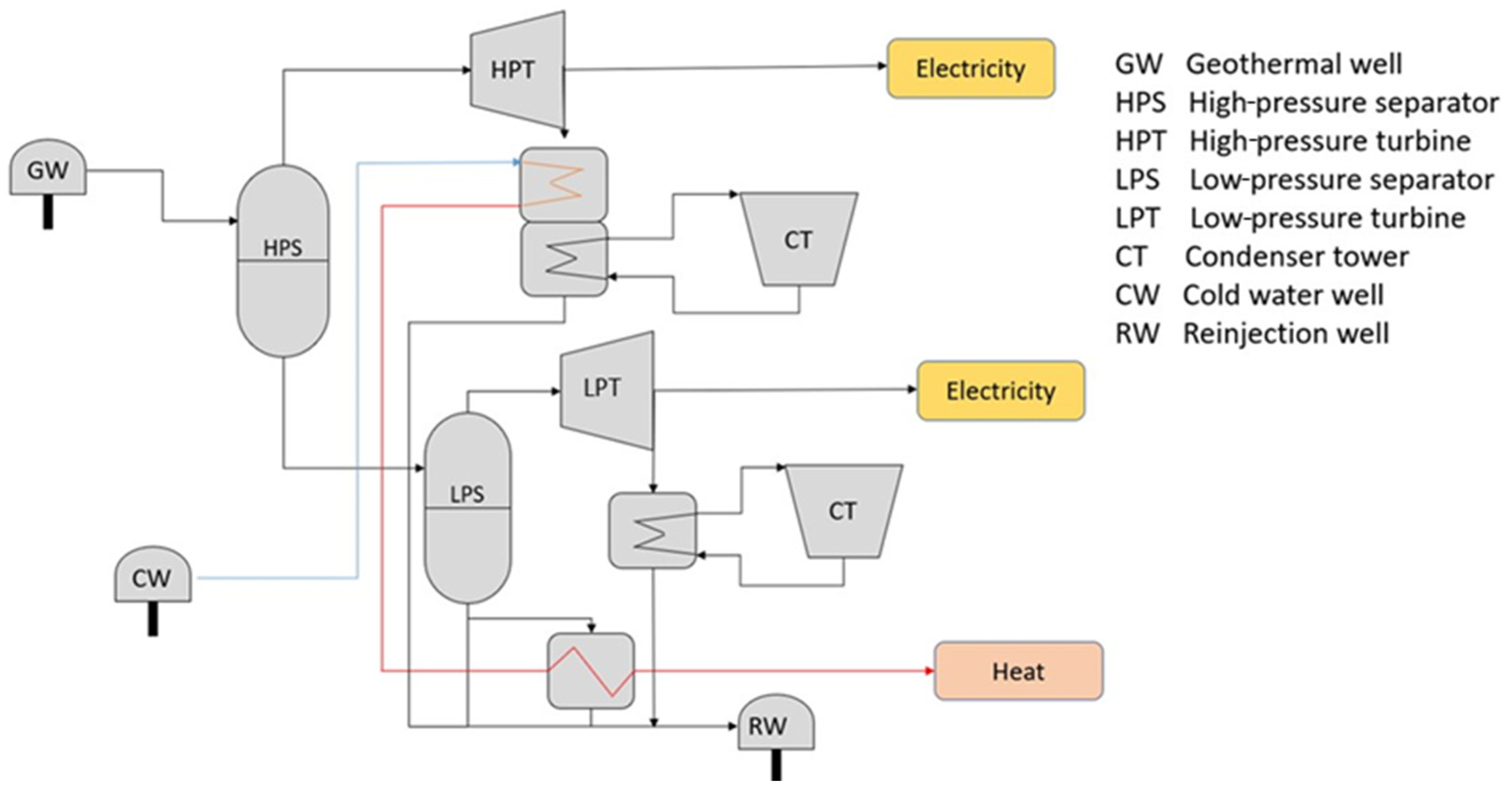
2.1. General Description of the Hellisheidi Power Plant

The Hellisheidi power plant is a flash-steam geothermal CHP plant located in southwest Iceland, around 30 km east of Iceland’s capital, Reykjavik. The power plant was commissioned in 2006, with an initial electricity (E) production capacity of 90 MWe and no heating (H), but has since then been developed further. Currently, the electric production capacity of the plant is 303 MWe, delivering electricity to Iceland’s national grid, and the thermal capacity is 133 MWt, supplying district heating to Iceland’s capital area.
The plant utilizes energy contained in the geothermal fluid extracted from deep wells (with average depths of 2247 m for wide wells and 2346 m for narrow wells) located around the plant. In this plant, there is 36 km of pipes. The two-phase fluid is run through insulated steel pipes to high-pressure separators, where the geothermal fluid is separated into steam and brine. The steam goes on to produce electricity in high-pressure turbines, while the brine goes through a second separation stage, where electricity is produced under a lower pressure. Hot water is produced by extracting fresh water and running it through heat exchangers located at the outlet of the high-pressure turbine and the outlet of the low-pressure separator. A simplified flow diagram for the Hellisheidi geothermal power plant is presented in Figure 1.
Since 2014, the abatement of CO2 and H2S has been ongoing at the Hellisheidi plant on an industrial scale. With the abatement methods, called CarbFix and SulFix, the CO2 and H2S coming from plant’s outlet are dissolved in water and reinjected through reinjection wells back into the basaltic rock formation. The CarbFix method has proven to be highly efficient, with 95% of the CO2 being mineralized within two years after reinjection [20]. This abatement technology requires additional piping to transport gas from the power plant and water. The fluids are transported to a water scrubbing system, where the gas dissolves in water and is thereafter transported via pipelines to reinjection wells. In 2017, the reinjection of CO2 and H2S amounted to 10,000 tons and 5000 tons, respectively. This corresponded to 34% and 68% of the plant’s annual emissions, respectively [20].
Reference data for the energy production in the Hellisheidi power plant are presented in Table 1. The included data correspond to production based on the average performance over a 30-year lifetime for both heat and power production. The operational data used in this work refer to 2020.

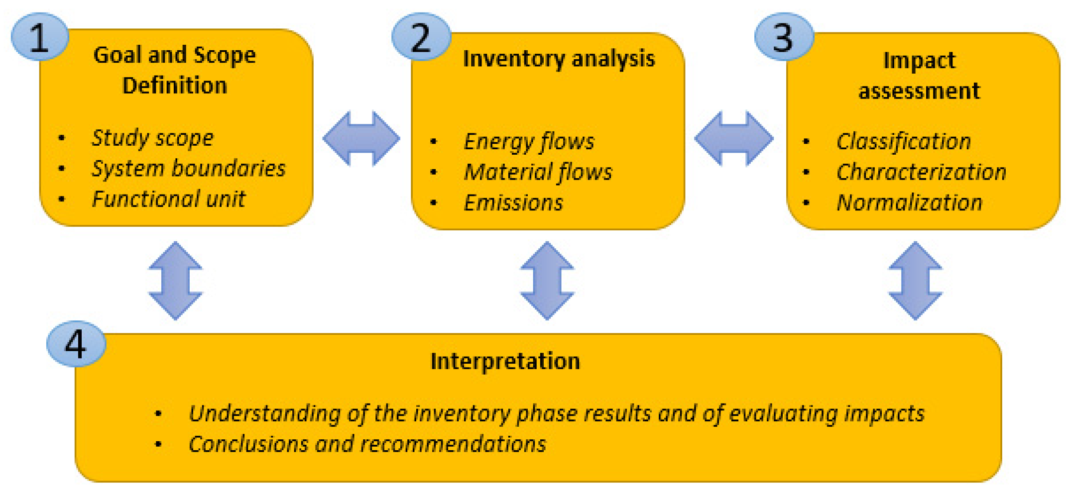
2.2. Life-Cycle Assessment (LCA) Methodology

LCA is a scientifically recognized methodology supported by the ISO standard 14040 series. As a general framework, LCA attempts to associate the emissions, resource extraction, and processes (i.e., inputs and outputs along the value chain) into environmental impact categories. The LCA approach has been widely recognized as a reference method that can be applied to the assessment of energy systems [7]. It has also demonstrated applicability for providing comparisons of geothermal systems with other renewable energy technologies [10,18], and to ensure comparability among LCA results from geothermal energy systems of different types and sizes [14].
Following the standard definition, this methodology is synthesized in four interrelated phases (see Figure 2) to harmonize its application: goal and scope definition, inventory analysis, impact evaluation, and the interpretation of results [14].

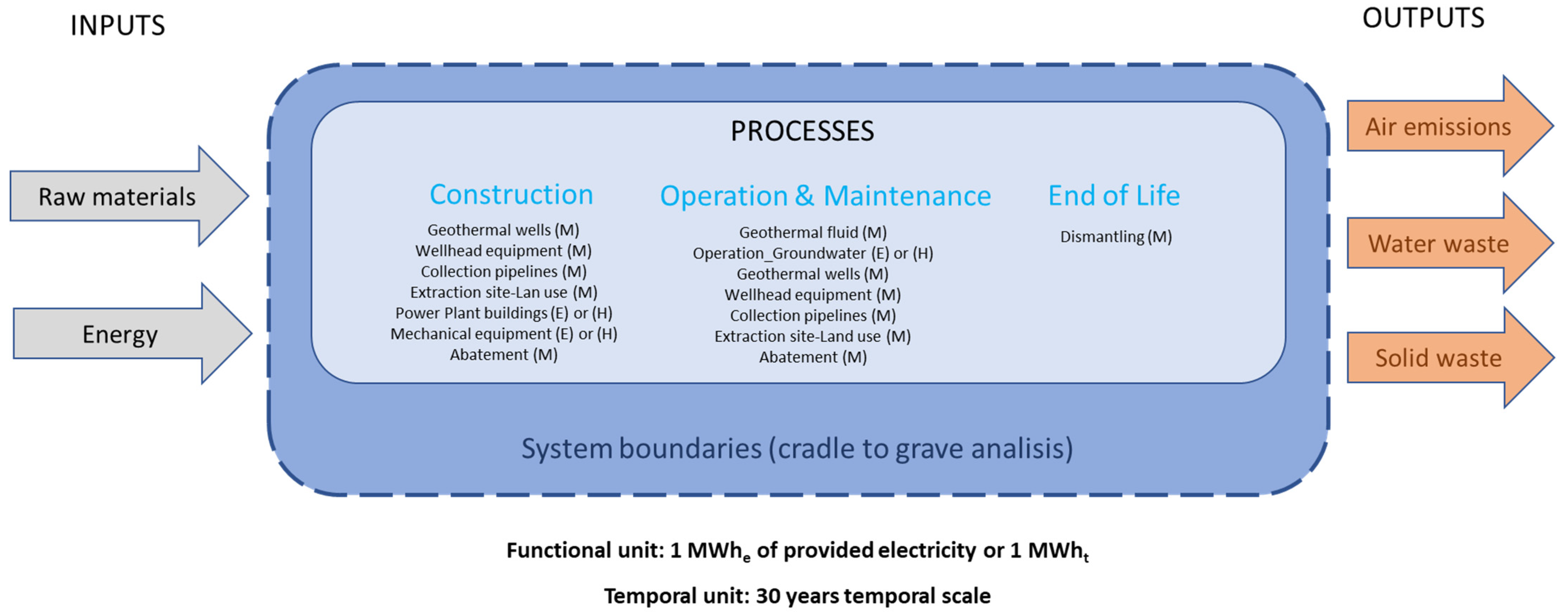
2.2.1. Goal and Scope

The main objective of this analysis was to quantify the magnitude of the environmental burden of the Hellisheidi double-flash cogeneration geothermal power plant based on applying exergy allocation factors. The material and energy burdens were quantified per functional unit, defined as the production of 1 kWh of electricity and 1 kWh of hot water for district heating. In addition, 30 years was considered as the timescale. All inputs and outputs related to the electricity and heat production processes were consistently managed and correlated based on these two references.
  • System description and boundaries
As can be seen in Figure 3, this study was based on the evaluation of the Hellisheidi power plant with a life-cycle perspective using a cradle-to-grave approach in order to develop a robust LCA study comparable to other geothermal systems.
The system boundaries defined in this study corresponded to the analysis of the power plant’s life-cycle stages. It comprised the assessment of the following phases: the construction, operation (including abatement operations and maintenance), and well closure of the geothermal plant (dismantling). This was similar to the system boundaries of the LCA study performed for other geothermal power plants worldwide, as reported by Tosti et al. for the Italian Bagnore geothermal power plant system [21].
The Hellisheidi power plant produces both electricity and hot water simultaneously. Some processes are exclusively attributable to the electricity product (i.e., E in Figure 3), while others are exclusively attributable to the heat product (i.e., H in Figure 3). Inevitably, there are also processes that are defined as multifunctional (i.e., M in Figure 3) and are used to produce both.
Due to multifunctional processes coexisting to simultaneously generate electricity and heat, there was a need to either assign or allocate the inputs and outputs to the relevant output flows [19]. Consequently, an allocation factor was considered according to a product logic that appropriately attributes material and energy inputs to properly quantify the corresponding environmental impacts to the respective outputs.
Several LCA studies have focused on evaluating the environmental performance of geothermal plants [20,22]. The majority of these works have been generally based on energy allocation [16,17] and the related cost allocation factor [18]. The allocation factor of energy means giving equal weight to electricity and heat, without taking into account that heat does not have the same energy quality as electricity. The allocation factor of the cost of energy does not consider the physical properties of energy, but only the economic ones. Other than these two options for allocation, a new approach that takes into account the physical properties of energy and homogenizes the two contributions by considering the quality of the energy (i.e., the exergy) has been identified to be less extensive [17,19]. This allocation procedure has been defined to deal with such multifunctionality as a proper allocation method, according to the ILCD Handbook [23]. This work applied an allocation factor based on exergy to provide new insights concerning the applicability of the latter option and attribute the environmental impacts to the power plant’s two main products.
  • Exergy allocation factors
In an analysis of energy systems, exergy can be considered as a representation of the qualities of different forms of energy by referring to the maximum work that can be obtained. In the case of electricity, there is correspondence. In fact, the amount of electricity produced is equal to the exergy (1). On the other hand, heat does not correspond directly to exergy. A conversion factor must be introduced, which is called the Carnot factor (2). This term depends on the temperatures of the two heat sources in which the exchange takes place (in this case, the geothermal fluid and the environment). The maximum work that can be produced by a heat source exchanging with the environment is represented by the Carnot cycle. Therefore, the exergy that results is equal to the product of the heat and the Carnot factor (3) [24]:
E x e l e c t r i c = W e l
θ = 1 T T e n v
E x t h e r m a l = Q θ
where Ex is the overall flow rate of exergy (kW, electricity or heat), θ is the Carnot factor (indicating the thermodynamic quality of the heat, depending on the average temperature of the heat interaction), and Q is the heat rate (kW). T and Tenv refer to the temperature of the system and of the environment, respectively, while Wel refers to the power rate (W).
The decision to use an allocation factor based on exergy derives from the intention to allocate the contribution of a mechanical component that is shared by the two energy systems—the heat exchanger at the output of the high-pressure turbine, which contributes to both the power plant and the heat production. In these terms, the system exergy converted from electricity and heat was chosen as the allocation factor to exclusively allocate all of the multifunctional processes (M).
Although the end products of the system are both forms of energy (i.e., electricity and heat), the allocation factor that determines the division of the environmental impacts between these two products is based on their exergy values. In other words, the exergy values corresponding to the two products were evaluated using the three equations above, and by summing the two contributions, the overall exergy produced by the system was determined. The exergy allocation factor is a ratio consisting of, in the numerator, the contribution of electrical exergy or heat exergy and, in the denominator, the overall exergy that is produced. As a result, the allocation factor applied for multifunctional processes was 93% in terms of electricity production and 7% for heat production. The electrical exergy and heat exergy were quantified by applying the corresponding exergy efficiency factors of 25% for heat and 100% for electricity to the net amounts of heat and power that were produced, as shown in Table 1.
  • Cutoff criteria
The cutoff criteria applied in this study considered the relative contributions of mass and energy to the functional unit. The following criteria were applied:
Materials: Flows of less than 1% of the cumulative mass were excluded because their environmental relevance was not a concern. However, it was ensured that the sum of the neglected material flows did not exceed 5% of the mass or environmental relevance.
Energy: Flows of less than 1% of the cumulative energy were excluded from this analysis.
In both cases, it was verified that the total neglected percentage was less than 3% with respect to all of the unit processes that were considered.

2.2.2. Life-Cycle Inventory (LCI)
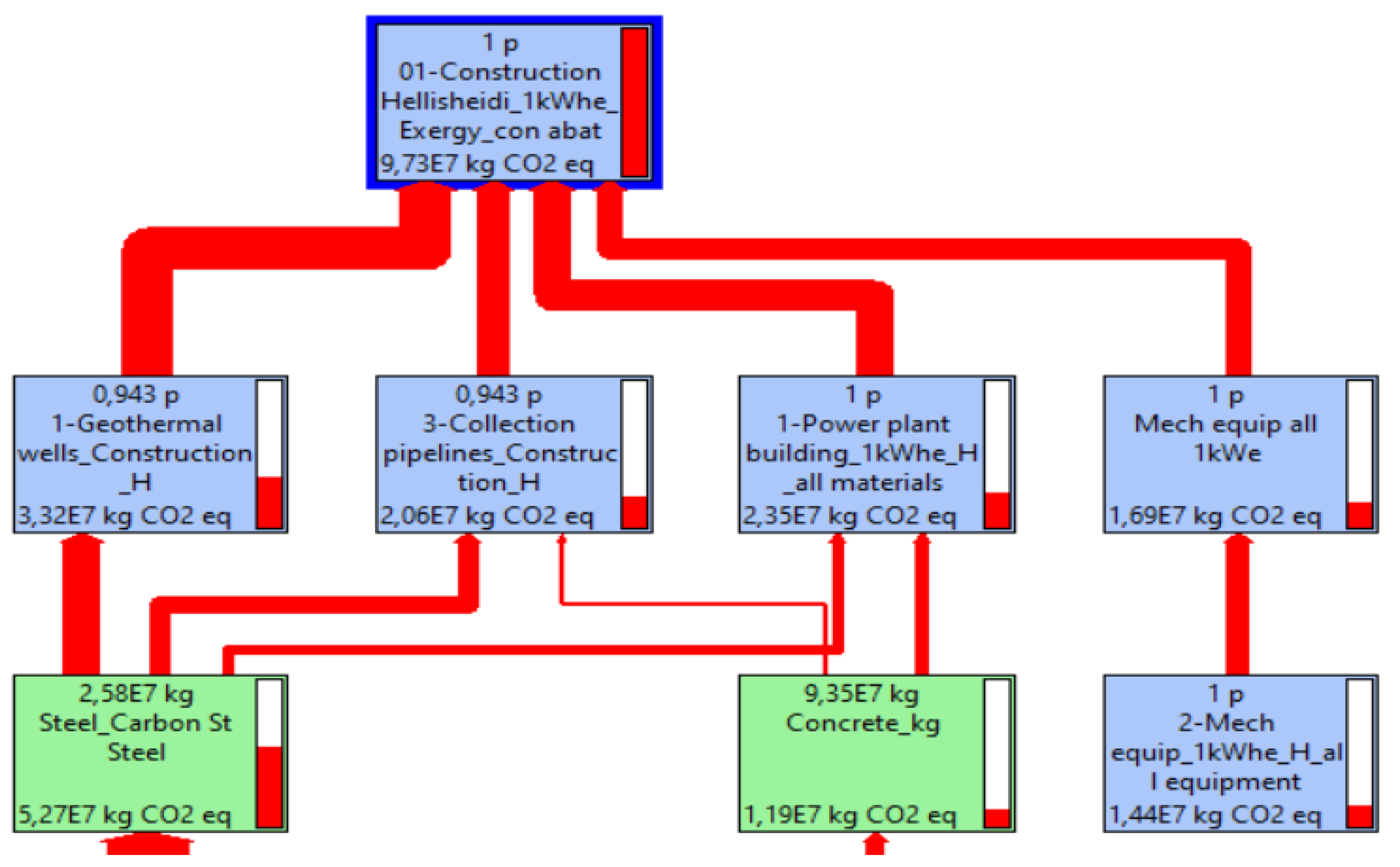
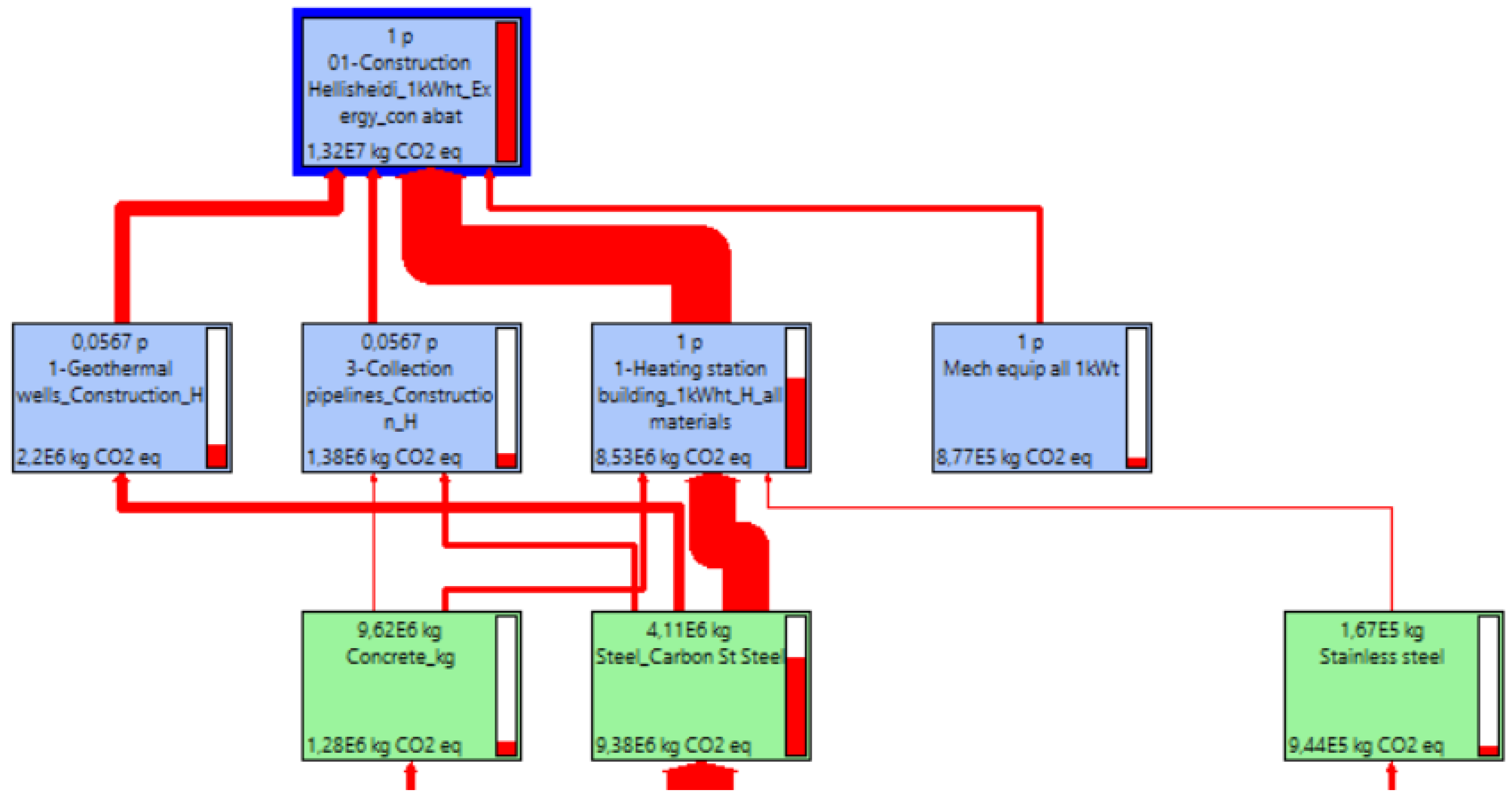
The LCI involved all of the inputs and outputs (i.e., energy and material) related to the system boundaries represented in Figure 3 for the geothermal power plant. In this work, firstly, an exhaustive review was conducted of previous inventories reported in the literature [13,16,17]. Based on this revision, primary data were initially collected for the three life-cycle stages, i.e., construction, operation and maintenance, and well closure. Secondly, the gathered data were updated to consider all of the improvements made to the geothermal power plant in terms of the wells (i.e., production, reinjection, and makeup), the installed capacity for power and heat production, the capacity factor, and the abatement equipment in recent years. Accordingly, this work presents the most updated data for the Hellisheidi geothermal power plant. Thirdly, all inputs and outputs were normalized according to the functional unit and timescale defined in the Goal and Scope Section. Finally, the generated inventory was then modeled by implementing ecoinvent v3.8—the most updated version of ecoinvent—compared to the previous studies based on ecoinvent v3.4. The most relevant information related to the life-cycle stages is included in the Supplementary Materials. Data concerning the main updated parameters of the wells are also included in this section.
  • Construction
This stage involved several processes related to the production of both power (E) and heat (H); therefore, they were considered as multifunctional processes (M). Other processes were only considered for power (P) or heat production. The processes assessed in this stage comprised the construction of geothermal wells (M), wellhead equipment (M), collection pipelines (M), power plant buildings (E and H), mechanical equipment (E and H), and extraction site land use (M). This stage also involved the construction of the abatement systems applied to both power and heat production.
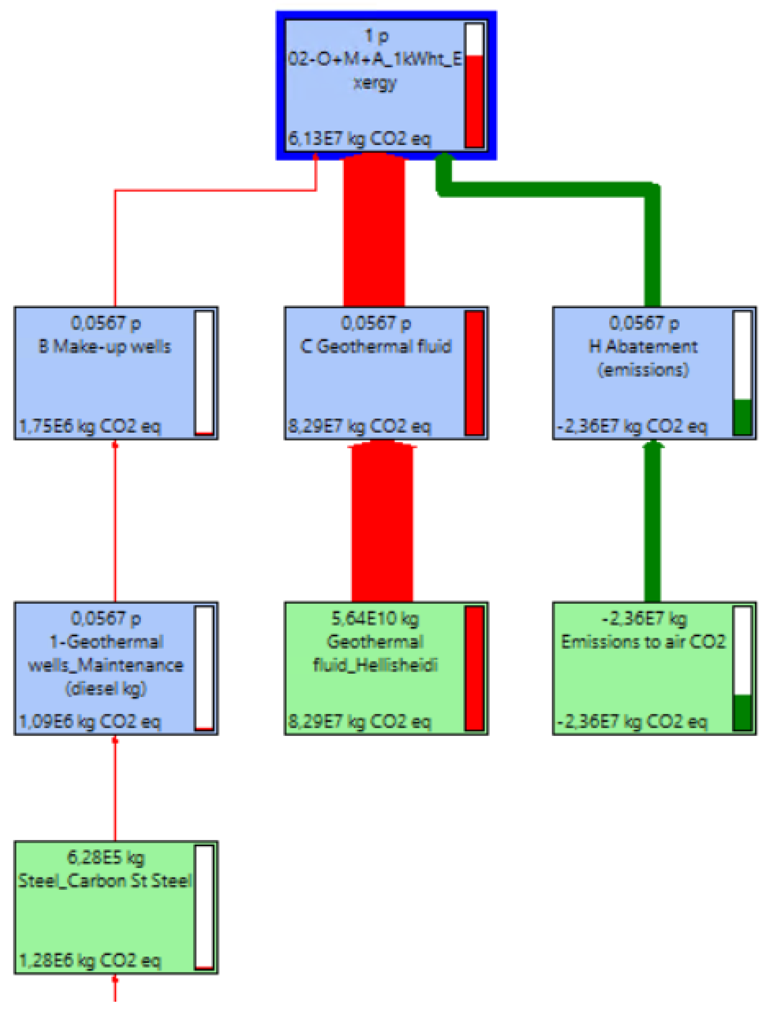
  • Operation and maintenance
This stage comprised inputs and outputs related to the operation and maintenance of the Hellisheidi geothermal power plant for power and heat production, including abatement processes. In terms of operation, the impacts were related to the consumption of geothermal fluid and groundwater. Concerning maintenance, the assessed inputs and outputs were those related to the makeup of the wells (i.e., the maintenance of the geothermal wells, wellhead equipment, and collection pipelines, as well as extraction site land use) and the chemicals required for maintenance and the replacement of mechanical components. Concerning the latter, 1% mechanical component replacement for power and heat production was assumed.
  • End of life
This stage is a multifunctional process that can be applied for both power and heating production. It was modeled in a simplified way due to the limitations of primary raw data. Accordingly, the inputs (materials) and outputs (wastes) considered in this work were related to the well closure of the geothermal plant (i.e., dismantling) after 30 years of operation. They were modeled by considering the well closure following a standard process of cementing, which was derived from ENEL GP data generated in the GEOENVI project [13].

2.2.3. Life-Cycle Impact Evaluation

In this study, the environmental analysis was developed using SimaPro software version Analyst 9.3.0.3. The ReCiPe 2016 v1.1 midpoint hierarchist method was the selected method of evaluation.
The ReCiPe midpoint method was selected because it is the one of the most recent and harmonized methods available in life-cycle impact assessment. The midpoint approach is considered to be more comprehensive for covering possible environmental interventions. It defines the environmental mechanism throughout the quantification of the impacts in the intermediate stages of the cause–effect chain. This approach allows for the calculation of 18 midpoint impact categories or environmental indicators. A detailed list of the indicators, with short descriptions, names, and acronyms, can be found in previous works [25,26]. This study explored the impacts related to all 18 midpoint impact categories—particularly the global warming potential (GWP, kg CO2 eq.).

3. Results and Discussion

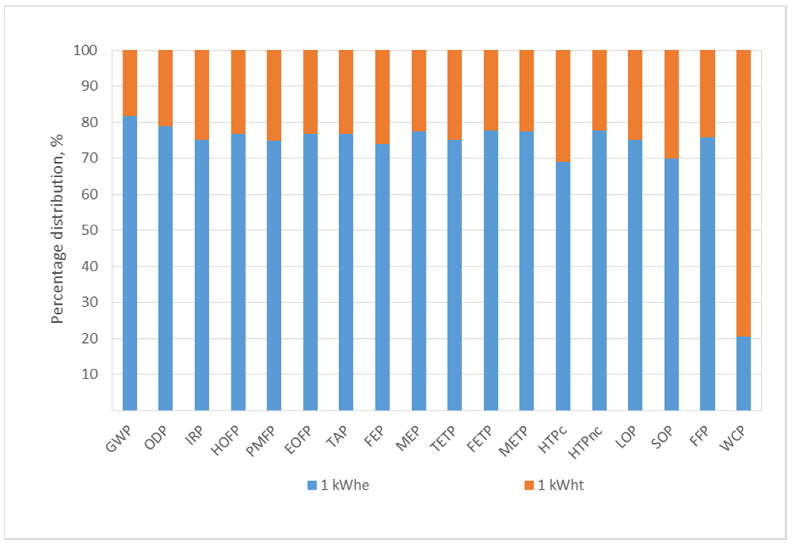
3.1. Assessment of Global Results

Figure 4 corresponds to the impacts related to the global process involving all of the life-cycle stages, based on the exergy allocation factor in terms of the normalized percentages of the 18 indicators that were studied. According to these results, electricity production (blue bars) represented the highest impact for almost all of the impact categories, except for water depletion. For this category, the orange bar (representing the impact fraction that was retraceable to heat production) was large (i.e., around 80%) due to the groundwater consumed for district heating production. This result was confirmed by performing a network analysis (see Figure 5).
In terms of the GWP, a total impact of 17.1 g CO2 eq. was attributed to the production of 1 kWhe of electricity, whereas 3.8 g CO2 eq. was related to the production of 1 kWht of heat, i.e., almost four times lower than the impact attributed to 1 kWhe of electricity production. This result for the GWP indicator is consistent with those presented by Karlsdottir et al. [17], who applied exergy allocation and the CML-IA baseline method. Karlsdottir et al. [17] determined that 1 kWh of electricity has an impact of ~20 g CO2 eq, whereas 1 kWh of heat generates ~5 g CO2 eq., i.e., 20% of the total impact in terms of the GHG emissions. The results for the combined production of heat and power indicated a total impact of 21 g CO2 eq/kWh, which was in the range of the results reported by Paulillo et al. [18], i.e., ~24 g CO2 eq. According to a study conducted by Paulillo et al. [18], the results for the Hellisheidi geothermal power plant were similar to those for other binary-cycle geothermal plants, as well as solar (photovoltaic) and hydropower plants; lower than those for other geothermal technologies and fossil-based technologies; and higher than those for nuclear and onshore wind. They also support the advantage of the LCA approach as a methodology to compare geothermal energy conversion with other renewable energy technologies, as reported by Zuffi et al. [10].

3.2. Assessment of Impacts in Terms of the Three Main Life-Cycle Stages

A more detailed comparison of the production processes was performed by considering the three life-cycle stages: construction, operation and maintenance, and end of life. The results presented in Figure 6 correspond to the related impacts based on the exergy allocation factor in terms of the normalized percentages for the 18 indicators that were studied. In this case, a similar tendency was identified for the two functional units, i.e., 1 kWhe of electricity production and 1 kWht of heat production.
The construction stage had a more significant environmental burden, with shares of around 60–70% and 70–80% for electricity and heat production, respectively, for almost all of the 18 indicators (see Figure 6a,b). An exception was found for GWP and WCP—the indicators where the construction stage had a rather low impact compared to the other two production processes. The impacts on these two indicators were mostly attributed to the OMA stage, with shares above 90% for both electricity and heat production. In particular, the stage of EoL was the one that had the lowest impact among all of the assessed indicators. The same trends can be seen in the work by A. Paulillo et al. [18], although the results were analyzed by taking into account the combination of both productions (i.e., heat and power).
To gain more insight into the GWP indicator results, a deeper analysis was carried out for the OMA stage by considering a network analysis with a node cutoff of 1% to produce 1 kWe and 1 kWt. As depicted in Figure 7 and Figure 8, similar trends were found for both processes. The abatement unit had benefits for CO2 reduction, although the impact of the CO2 emitted during the operation (i.e., geothermal fluid consumption) most affected the final result. Additional impacts on the GWP indicator were due to the consumption of steel related to the makeup of the wells. The results attained for the WCP indicator were mostly affected by the water consumption during the operation of the Hellisheidi geothermal power plant.

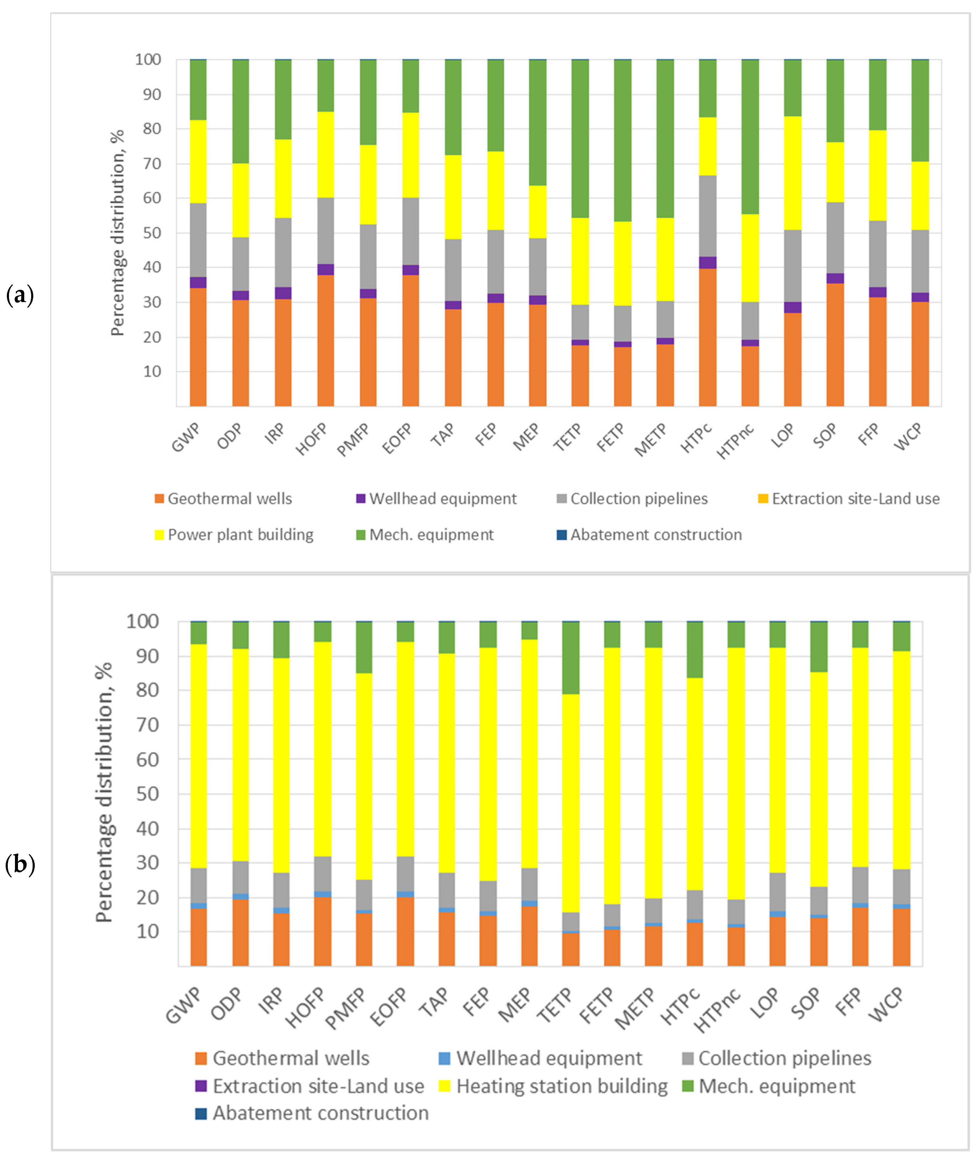
3.3. Environmental Impacts Related to Construction

Figure 9 is included to assess the environmental burden attained for the construction stage in terms of each impact category. The results are depicted for the 18 indicators, which were studied as normalized percentages. In this case, there were differences among the environmental burdens obtained for the two functional units defined in the production processes. On the one hand, in terms of electricity production, the mechanical equipment, geothermal wells, and power plant building had more significant impacts. In particular, the mechanical equipment exhibited a share of around 30–40% for indicators related to eutrophication and ecotoxicity. In addition, the geothermal wells generally had the highest contributions in the other impact categories, with estimates around 30%—particularly for those related to global warming and resource scarcity.
On the other hand, in terms of heating production, the heating station building yielded the highest environmental burden for the 18 categories, with an estimate of around 60% of the total impact. The geothermal well construction also had relevance compared to the remaining processes in the heat production stage. These results indicated trends similar to those presented in the literature by Colucci et al. [19] based on the inventories of 2015 and 2017 (older raw data).
A detailed assessment of the results was performed to elucidate the environmental burden attained for the GWP indicator. In this vein, a network analysis was performed with a node cutoff of 9% for the production of 1 kWe and 1 kWt in terms of the impact category that was explored.
According to Figure 10, the steel consumed during the geothermal well construction and the concrete associated with the power plant building were materials that substantially affected the environmental burden attained in the construction stage. A similar analysis for the other indicators was useful to elucidate the materials causing the related impacts.
Concerning 1 kWt, the results for the GWP indicator yielded similar trends. The impacts were substantially affected by the consumption of steel that was required for the construction of the heating station (see Figure 11).

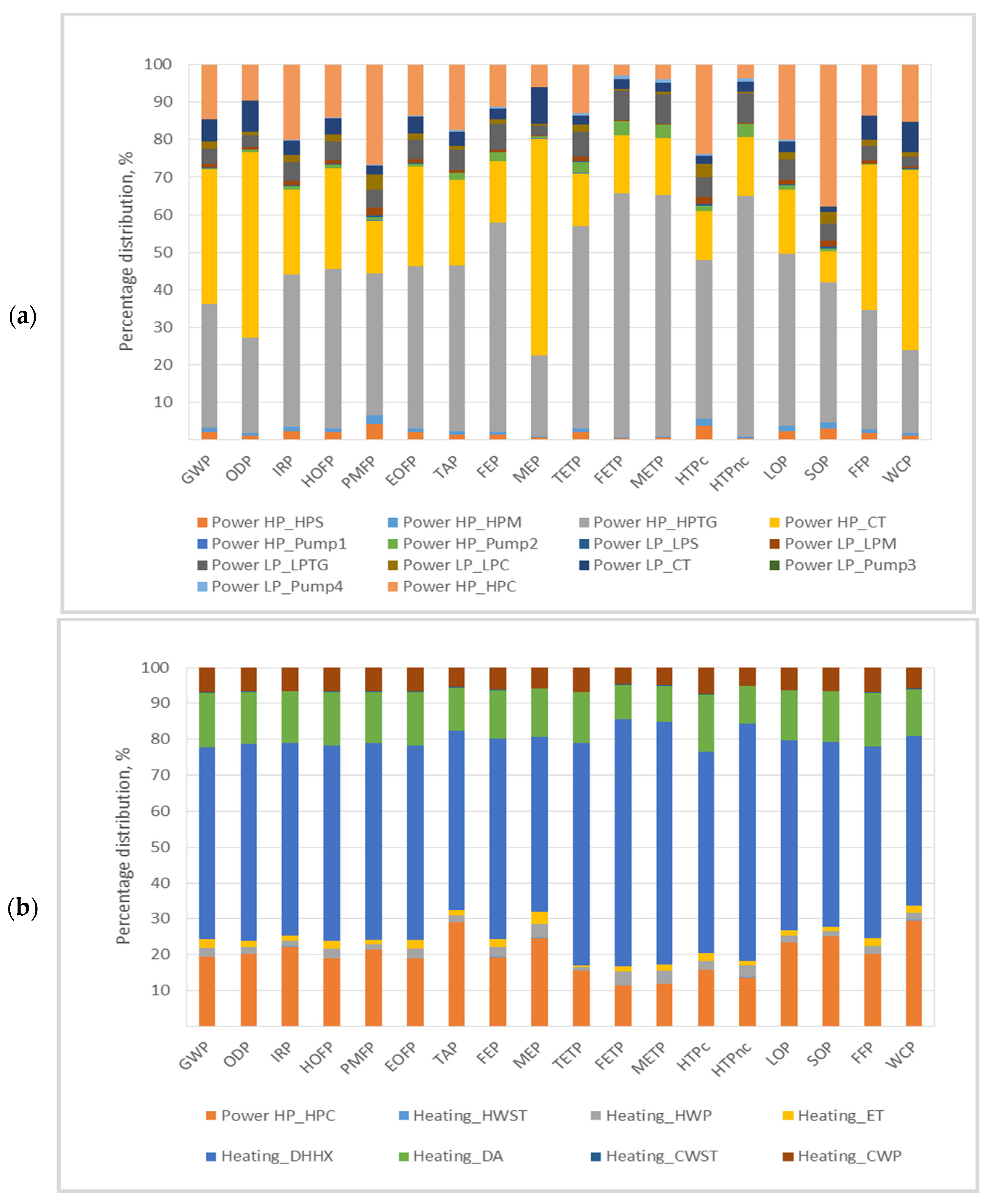
3.4. Influence of Mechanical Equipment on the Environmental Impact of the Plant

In this section, special attention was devoted to assessing the environmental burden attributed to the mechanical equipment components of the plant. The results are depicted in Figure 12.
According to Figure 12, in terms of electricity production, the HPTG (turbine generator) was the equipment with the most significant estimate for the environmental burden of the plant. Other equipment of relevance included the HP_CT (cooling tower) and the HP_HPC (condenser). These results are consistent with the results reported by Colucci et al. [19] based on the inventories of 2015 and 2017 (older raw data).
Regarding heating production, the DHHX (heat exchanger for district water heating) was the equipment with the most relevant effect on the environmental impact of the heating production. Other relevant equipment included the HP_HPC (condenser) and DA (deaerator). Similar trends were reported by Colucci et al. [19] based on inventories that were older than those applied in this study for the Hellisheidi CHP plant.
These results imply that improvements should be focused on the eco-design of the mentioned equipment to improve the sustainability of this geothermal power plant.

4. Conclusions

This work was dedicated to an environmental assessment of the Hellisheidi power plant. This study aimed to elucidate the environmental impacts of electricity and heat production at this double-flash geothermal power plant. In this vein, firstly, the most updated inventory of the plant was generated. Primary raw data concerning the geothermal wells and different technical parameters, along with secondary data from the database used for the LCA modeling, were updated.
Secondly, the LCI data were allocated based on the exergy approach, and the material and energy burdens were normalized per functional unit of 1 kWh of net electricity and 1 kWt of net heat produced. A cradle-to-grave approach was used; therefore, the life-cycle stages that were included were the (i) construction, (ii) operation (including abatement operations and maintenance), and (iii) well closure of the geothermal plant. All of the life-cycle stages from construction to dismantling were considered.
Based on the application of the exergy allocation method, the results highlighted that that the production of electricity represents most of the environmental impact of the Hellisheidi geothermal power plant, and that district heating, for almost all categories, represents a share of around 20%. In particular, in terms of the GWP, a total impact of 17.1 g CO2 eq. was attributed to the production of 1 kWhe of electricity, whereas 3.8 g CO2 eq. was related to the production of 1 kWht of heat, i.e., almost four times lower than the impact attributed to 1 kWhe of electricity production, as expected for this type of geothermal power plant based on previous reports.
The results in terms of the three life-cycle stages determined that the construction stage was the main contributor to the global environmental burden of the entire system for 16 of the 18 indicators, with shares of around 60–70% and 70–80% for electricity and heat production, respectively. For the other two indicators, i.e., GWP and WCP, the OMA stage was the dominant one, with a share above 90% for electricity and heat production. The impacts on these two indicators were due to the GHGs emitted and the water consumed during the plant’s operation, respectively. A positive effect was elucidated for the abatement units, which were also recognized to provide credits for minimizing CO2 emissions, as expected. The EoL stage was the one that had the lowest impact for all of the assessed indicators.
A deeper assessment of the construction stage showed that in terms of electricity production, the impacts were mostly attributed to the mechanical equipment, geothermal wells, and power plant building. In particular, the mechanical equipment exhibited a share of around 30–40% for indicators related to eutrophication and ecotoxicity. The geothermal wells generally had the highest contributions in the other impact categories, with an estimate of around 30% of the total impact in the construction stage—particularly for categories related to global warming and resource scarcity. In terms of the heating production, the heating station building yielded the highest environmental burden, with an estimate of around 60% of the total impact. For both electricity and heating production, the results were mostly related to the consumption of materials such as steel and concrete.
Finally, in terms of equipment, it was shown that the HPTG (turbine generator) most affected the environmental performance of the electricity production process. Furthermore, the DHHX (heat exchanger for district water heating) was the equipment with the most relevant effect on the environmental impact of the heating production.
Accordingly, improvements in equipment construction could provide better performance in terms of the environmental burden of the Hellisheidi geothermal power plant.

Supplementary Materials

The following supporting information can be downloaded at https://www.mdpi.com/article/10.3390/en16093616/s1.

Author Contributions

Conceptualization, M.D.-R., S.J., C.Z., M.D.M.-T. and G.M.; methodology, M.D.-R., C.Z. and G.M.; formal analysis and writing—original draft preparation, M.D.-R., S.J., C.Z., M.D.M.-T. and G.M.; writing—review and editing, M.D.-R. All authors have read and agreed to the published version of the manuscript.

Funding

This research received funding from the European Union’s Horizon 2020 Research and Innovation program under grant agreement No. 818169, the GECO project (Geothermal Emission Control, https://geco-h2020.eu/ accessed on 20 April 2023).

Data Availability Statement

The data presented in this study are available in the supplementary material here. Additional data is not available due to confidential issues.

Acknowledgments

The authors express their gratitude to the GECO project’s partners for their support in the development of this study.

Conflicts of Interest

The authors declare no conflict of interest.

Nomenclature

EoLEnd of life
EOFPOzone formation (terrestrial ecosystems)
Ex_electricWork exergy
Ex_ThermalHeat exergy
FEPFreshwater eutrophication
FETPFreshwater ecotoxicity
FFPFossil resource scarcity
GWPGlobal warming
HOFPOzone formation (human health)
HTPcHuman carcinogenic toxicity
HTPncHuman non-carcinogenic toxicity
IRPIonizing radiation
LCALife-cycle analysis or assessment
LCILife-cycle inventory
LOPLand use
MEPMarine eutrophication
METPMarine ecotoxicity
ODPStratospheric ozone depletion
OMAOperation, maintenance, and abatement operation
PMFPFine particulate matter formation
QHeat (W)
RESRenewable energy systems
SOPMineral resource scarcity
TTemperature of the system (° K)
T_envTemperature of environment
TAPTerrestrial acidification
TETPTerrestrial ecotoxicity
WCPWater consumption
W_elPower (electricity) (W)
θCarnot factor

References

  1. Paulillo, A.; Kim, A.; Mutel, C.; Striolo, A.; Bauer, C.; Lettieri, P. Influential parameters for estimating the environmental impacts of geothermal power: A global sensitivity analysis study. Clean. Environ. Syst. 2021, 3, 100054. [Google Scholar] [CrossRef]
  2. MDíaz-Ramírez, C.; Blecua-de-Pedro, M.; Arnal, A.; Post, J. Acid/base flow battery environmental and economic performance based on its potential service to renewables support. J. Clean. Prod. 2022, 330, 129529. [Google Scholar] [CrossRef]
  3. Arnal, Á.; Dıáz-Ramırez, M.; Acevedo, L.; Ferreira, V.; Garcıá-Armingol, T.; López-Sabiron, A.; Ferreira, G. Multicriteria analysis for retrofitting of natural gas melting and heating furnaces for sustainable manufacturing and industry 4.0. J. Energy Resour. Technol. Trans. ASME 2020, 142, 022203. [Google Scholar] [CrossRef]
  4. Royo, P.; Acevedo, L.; Arnal, Á.; Diaz-Ramírez, M.; García-Armingol, T.; Ferreira, V.; Ferreira, G.; López-Sabirón, A. Decision Support System of Innovative High-Temperature Latent Heat Storage for Waste Heat Recovery in the Energy-Intensive Industry. Energies 2021, 14, 365. [Google Scholar] [CrossRef]
  5. Tomasini-Montenegro, C.; Santoyo-Castelazo, E.; Gujba, H.; Romero, R.; Santoyo, E. Life Cycle Assessment of Geothermal Power Generation Technologies: An Updated Review. Appl. Therm. Eng. 2017, 114, 1119–1136. [Google Scholar] [CrossRef]
  6. Paulillo, A.; Kim, A.; Mutel, C.; Striolo, A.; Bauer, C.; Lettieri, P. Simplified models for predicting the environmental impacts of geothermal power generation. Clean. Environ. Syst. 2022, 6, 100086. [Google Scholar] [CrossRef]
  7. Hemeida, M.; Hemeida, A.; Senjyu, T.; Osheba, D. Renewable Energy Resources Technologies and Life Cycle Assessment: Review. Energies 2022, 15, 9417. [Google Scholar] [CrossRef]
  8. Douziech, M.; Tosti, L.; Ferrara, N.; Parisi, M.; Pérez-López, P.; Ravier, G. Applying harmonised geothermal life cycle assessment guidelines to the rittershoffen geothermal heat plant. Energies 2021, 14, 3820. [Google Scholar] [CrossRef]
  9. Milousi, M.; Pappas, A.; Vouros, A.; Mihalakakou, G.; Souliotis, M.; Papaefthimiou, S. Evaluating the Technical and Environmental Capabilities of Geothermal Systems through Life Cycle Assessment. Energies 2022, 15, 5673. [Google Scholar] [CrossRef]
  10. Zuffi, C.; Manfrida, G.; Asdrubali, F.; Talluri, L. Life cycle assessment of geothermal power plants: A comparison with other energy conversion technologies. Geothermics 2022, 104, 102434. [Google Scholar] [CrossRef]
  11. Frick, S.; Kaltschmitt, M.; Schröder, G. Life cycle assessment of geothermal binary power plants using enhanced low-temperature reservoirs. Energy 2010, 35, 2281–2294. [Google Scholar] [CrossRef]
  12. Pratiwi, A.; Ravier, G.; Genter, A. Life-cycle climate-change impact assessment of enhanced geothermal system plants in the Upper Rhine Valley. Geothermics 2018, 75, 26–39. [Google Scholar] [CrossRef]
  13. GEOENVI Project: Tackling the Environmental Concerns for Deploying Geothermal Energy in Europe, Grant agreement ID: 818242. (2018–2021). Available online: https://www.geoenvi.eu/ (accessed on 20 April 2023).
  14. Parisi, M.; Douziech, M.; Tosti, L.; Pérez-López, P.; Mendecka, B.; Ulgiati, S.; Fiaschi, D.; Manfrida, G.; Blanc, I. Definition of LCA Guidelines in the Geothermal Sector to Enhance Result Comparability. Energies 2020, 13, 3534. [Google Scholar] [CrossRef]
  15. Parisi, M.; Ferrara, N.; Torsello, L.; Basosi, R. Life cycle assessment of atmospheric emission profiles of the Italian geothermal power plants. J. Clean. Prod. 2019, 234, 881–894. [Google Scholar] [CrossRef]
  16. MKarlsdóttir, R.; Pálsson, Ó.; Pálsson, H.; Maya-Drysdale, L. Life cycle inventory of a flash geothermal combined heat and power plant located in Iceland. Int. J. Life Cycle Assess. 2015, 20, 503–519. [Google Scholar] [CrossRef]
  17. MKarlsdottir, R.; Heinonen, J.; Palsson, H.; Palsson, O. High-Temperature Geothermal Utilization in the Context of European Energy Policy—Implications and Limitations. Energies 2020, 13, 3187. [Google Scholar] [CrossRef]
  18. Paulillo, A.; Striolo, A.; Lettieri, P. The environmental impacts and the carbon intensity of geothermal energy: A case study on the Hellisheiði plant. Environ. Int. 2019, 133, 105226. [Google Scholar] [CrossRef] [PubMed]
  19. Colucci, V.; Manfrida, G.; Mendecka, B.; Talluri, L.; Zuffi, C. LCA and Exergo-Environmental Evaluation of a Combined Heat and Power Double-Flash Geothermal Power Plant. Sustainability 2021, 13, 1935. [Google Scholar] [CrossRef]
  20. Karlsdottir, M.; Heinonen, J.; Palsson, H.; Palsson, O. Life Cycle Assessment of a Geothermal Combined Heat and Power Plant Based on High Temperature Utilization. Geothermics 2020, 84, 101727. [Google Scholar] [CrossRef]
  21. Tosti, L.; Ferrara, N.; Basosi, R.; Parisi, M. Complete Data Inventory of a Geothermal Power Plant for Robust Cradle-to-Grave Life Cycle Assessment Results. Energies 2020, 13, 2839. [Google Scholar] [CrossRef]
  22. Basosi, R.; Bonciani, R.; Frosali, D.; Manfrida, G.; Parisi, M.; Sansone, F. Life Cycle Analysis of a Geothermal Power Plant: Comparison of the Environmental Performance with Other Renewable Energy Systems. Sustainability 2020, 12, 2786. [Google Scholar] [CrossRef]
  23. European Commission. Joint Research Centre. International Reference Life Cycle Data System. (ILCD) Handbook: Framework and Requirements for Life Cycle Impact Assessment Models and Indicators; Publications Office of the European Union: Luxembourg, 2010; ISBN 978-92-79-17539-8. ISSN 1018-5593. [Google Scholar] [CrossRef]
  24. Sayyaadi, H. Modelling, Assessment, and Optimization of Energy Systems; Academic Press: London, UK, 2021; ISBN 978-0-12-816656-7. [Google Scholar]
  25. Díaz-Ramírez, M.; Ferreira, V.; García-Armingol, T.; López-Sabirón, A.; Ferreira, G. Battery manufacturing resource assessment to minimise component production environmental impacts. Sustainability 2020, 12, 6840. [Google Scholar] [CrossRef]
  26. Díaz-Ramírez, M.; Ferreira, V.; García-Armingol, T.; López-Sabirón, A.; Ferreira, G. Environmental Assessment of Electrochemical Energy Storage Device Manufacturing to Identify Drivers for Attaining Goals of Sustainable Materials 4.0. Sustainability 2020, 12, 342. [Google Scholar] [CrossRef]
Figure 1. Schematic representation of the Hellisheidi power plant.
Energies 16 03616 g001
Figure 2. Interrelated LCA phases.
Energies 16 03616 g002
Figure 3. System boundaries defined for the environmental assessment (LCA) of the Hellisheidi geothermal power plant. M: multifunctional process; E: process applied to electricity production; H: process applied to heat production.
Energies 16 03616 g003
Figure 4. Environmental impacts related to production of 1 kWe and 1 kWt.
Energies 16 03616 g004
Figure 5. Network analysis of water consumption indicator related to production of 1 kWt.
Energies 16 03616 g005
Figure 6. Environmental impacts related to each life-cycle stage: (a) Results of production of 1 kWe. (b) Results of production of 1 kWt.
Energies 16 03616 g006aEnergies 16 03616 g006b
Figure 7. Network analysis of the OMA stage for the global warming indicator, with a node cutoff of 1%. The results refer to the production of 1 kWe.
Energies 16 03616 g007
Figure 8. Network analysis of the OMA stage for the global warming indicator, with a node cutoff of 1%. The results refer to the production of 1 kWt.
Energies 16 03616 g008
Figure 9. Environmental impacts related to the construction stage: (a) Results of the production of 1 kWe. (b) Results of the production of 1 kWt.
Energies 16 03616 g009
Figure 10. Network analysis of the construction stage for the production of 1 kWe. The results refer to the global warming indicator, with a node cutoff of 9%.
Energies 16 03616 g010
Figure 11. Network analysis of the construction stage for the production of 1 kWe. The results refer to the global warming indicator, with a node cutoff of 6%.
Energies 16 03616 g011
Figure 12. Environmental impacts related to the mechanical equipment: (a) Results of the production of 1 kWe. (b) Results of the production of 1 kWt.
Energies 16 03616 g012
Table 1. Main characteristics of the Hellisheidi power plant.
Power PlantElectricity ProductionHeat Production
Installed capacity (MW)303133
Capacity factor (dimensionless)0.870.55
Net electricity in 30 years (GWh)65963---
Net heat in 30 years (GWh)---1922
Disclaimer/Publisher’s Note: The statements, opinions and data contained in all publications are solely those of the individual author(s) and contributor(s) and not of MDPI and/or the editor(s). MDPI and/or the editor(s) disclaim responsibility for any injury to people or property resulting from any ideas, methods, instructions or products referred to in the content.

