Review

Diffusion Absorption Refrigeration Systems: An Overview of Thermal Mechanisms and Models

by
Baby-Jean Robert Mungyeko Bisulandu
1,2,
Rami Mansouri
1 and
Adrian Ilinca
3,*
1
Laboratoire de Recherche en Energie Eolienne (LREE), Université du Québec à Rimouski (UQAR), 300 All. des Ursulines, Rimouski, QC G5L 3A1, Canada
2
Institut de Recherche Futuris—Futuris Research Institute (InReF), OEFC & Faculté Polytechnique, Université Kongo, Mbanza-Ngungu P.B. 202, Kongo Central, Democratic Republic of the Congo
3
Département de Génie Mécanique, École de Technologie Supérieure, Université du Québec, 1100, Rue Notre-Dame Ouest, Montréal, QC H3C 1K3, Canada
*
Author to whom correspondence should be addressed.
Energies 2023, 16(9), 3610; https://doi.org/10.3390/en16093610
Submission received: 16 March 2023 / Revised: 3 April 2023 / Accepted: 18 April 2023 / Published: 22 April 2023
(This article belongs to the Special Issue The Future of Renewable Energies)

Abstract

:
The energy transition, originating in the limitation of fossil resources and greenhouse gas (GHG) emission reduction, is the basis of many studies on renewable energies in different industrial applications. The diffusion absorption refrigeration machines are very promising insofar as they allow the use of renewable resources (solar, geothermal, waste gas, etc.). This technology is often considered an alternative to vapor compression systems in cooling and refrigeration applications. This paper aims to overview the thermal mechanisms related to modeling system energy sources and highlight the primary methodologies and techniques used. We study and analyze the technology’s current challenges and future directions and, finally, identify the gaps in the existing models to pave the way for future research. The paper also gives a classification of absorption refrigeration systems (ARS) to position and limit the scope of the study. The paper will help researchers who approach the various aspects to have a global synthetic analysis of the mechanisms characterizing the modeling of energy sources of absorption refrigeration machines.

Highlights

  • Analytical models of the diffusion or/and absorption of refrigerator energy sources are presented.
  • Designs and technologies of generators and bubble pumps are discussed.
  • Different optimization strategies for the energy performance of refrigeration machines are presented and discussed.

1. Introduction

Due to many countries’ fossil fuel depletion and energy-saving policies, absorption chillers are increasingly considered an alternative to compression chillers. Absorption chillers can operate on relatively low energy sources, such as solar heat, geothermal energy, and waste gas heat from industrial processes. The trend of absorption refrigeration machines is explained by the reserve reduction of fossil fuel and non-renewable resources that increase purchase costs. Data from the International Institute of Refrigeration (IIF) show that 17% of the world’s electricity production is consumed to meet thermal comfort needs such as cooling and heating. Conventional air-conditioning and refrigeration systems mostly use energy from non-renewable sources such as coal, oil, and natural gas [1].
Today, the concept of the energy transition, a policy to promote the use of green energies (considered less polluting), strongly encourages the refrigeration sector in its march towards the full use of sustainable systems (absorption refrigeration machines). According to Asfand and Bourouis [2], the world is facing an energy shortage problem. It is expected that the interest in absorption refrigeration systems will increase in the future because they can use renewable energy sources and environmentally friendly refrigerants that do not contribute to the depletion of the ozone layer. Many absorption refrigeration machine designs have been developed and installed in different countries. Much research is being carried out to realize economic and efficient thermal systems. It is a question of being able to choose and dimension in an optimal way the various constituent elements of the system (absorber, generator (or boiler), energy source, condenser, evaporator, heat exchanger (possibly), pump (possibly), etc.), or to be able to combine various technologies (combination of compression and absorption machines) or to combine several energy sources. It is essential to underline that absorption machines’ development is becoming increasingly important for air conditioning and conservation applications [3,4,5,6,7].
Thus, this paper aims to provide a comprehensive overview of the different thermal mechanisms related to modeling system energy sources, bubble generator/pump designs and technologies, methodologies, and techniques. It also aims to study and analyze the current challenges and future technology directions and, finally, to identify the shortcomings of existing models to mark out the road towards a mastered technology.
Several works in the literature explore diffusion absorption refrigeration machines using different energy sources [2,3,4,8,9,10,11,12,13,14,15,16,17,18,19,20,21,22,23,24,25,26,27,28,29,30,31,32,33,34,35,36,37,38,39,40,41,42]. For example, Dhindsa [43] discussed the different energy sources, including flat plate collectors, heat storage mediums, motor waste heat, phase change materials, and thermochemical absorption solar hybrid refrigeration systems.
In addition to the actual refrigeration machines, there are absorption chillers, which are the focus of the present research. Generally, water/NH3 and LiBr/water are refrigerants often used for absorption chillers. However, nowadays, many researchers use other fluid mixtures (LiNO3/NH3, LiBr + ZnBr2/CH3OH, LiNO3 + KNO3 + NaNO3/water, LiCl/water, Glycerol/water) to increase the system performance. Therefore, several authors have researched absorption chillers, including Medrano et al. [44]. They performed a refrigeration machine performance study, making mixtures of organic fluids trifluoroethanol (TFE)-tetraethylene glycol dimethyl ether (TEGDME or E181) and methanol-TEGDME. Alcântara et al. [45] focused on developing a mathematical model capable of simulating the quasi-dynamic behavior of absorption chillers using NH3/LiNO3 as the working fluid. Srikhirin et al. [13] stated that when a volatile absorbent such as water/NH3 is used, the system requires an additional component called a “rectifier,” which will purify the refrigerant before entering the condenser. Since the absorbent (water) is very volatile, it evaporates with ammonia (refrigerant). Without the rectifier, this water will condense and accumulate inside the evaporator, resulting in reduced performance.
The originality of the present article is that it gives a global overview of the thermal mechanisms involved in diffusion absorption refrigeration machines, emphasizing the choice of energy sources and existing generator technology.

2. A Brief Classification of Absorption Refrigeration Machines

The main thermal mechanisms involved in diffusion absorption refrigeration (DAR) systems are summarized as follows [32,33,34,35,36,37,38,39,40,41,42]:
-
The cooling capacity of such a machine depends on the diffusion rate of ammonia in the neutral gas, most commonly hydrogen;
-
The use of inert gas to regulate the pressure in the circuit (to keep the pressure constant). As such, the DAR machine operates at a single pressure level;
-
The heat exchangers allow the heating of the ammonia solution (used generally) sent to the generator. This exchange is possible thanks to the weak solution that enters the absorber. The other exchanger allows lowering the temperature of the solution coming from the condenser to reach the lowest possible temperature at the evaporator.
The main differences between the diffusion absorption refrigeration system and the traditional absorption refrigeration system are summarized [32,33,34,35,36,37,38,39,40,41,42]:
Diffusion–Absorption Refrigeration Systems
-
Ternary mixture: refrigerant, absorbent, and inert gas;
-
The use of two pairs of heat exchangers;
-
No pump or expansion valve;
-
These machines, using the water–ammonia couple, are used mostly for household applications;
-
The DAR is a single-pressure system;
-
The presence of inert gas, often hydrogen;
-
The coefficient of performance rarely exceeds 1.
Traditional Absorption Refrigeration Systems
-
Binary mixture;
-
Existence of a single heat exchanger;
-
Existence of 2 pressure levels: high-pressure (HP) and low-pressure (LP) (bi-pressure);
-
Use a pump and a regulator because of the two pressure levels.

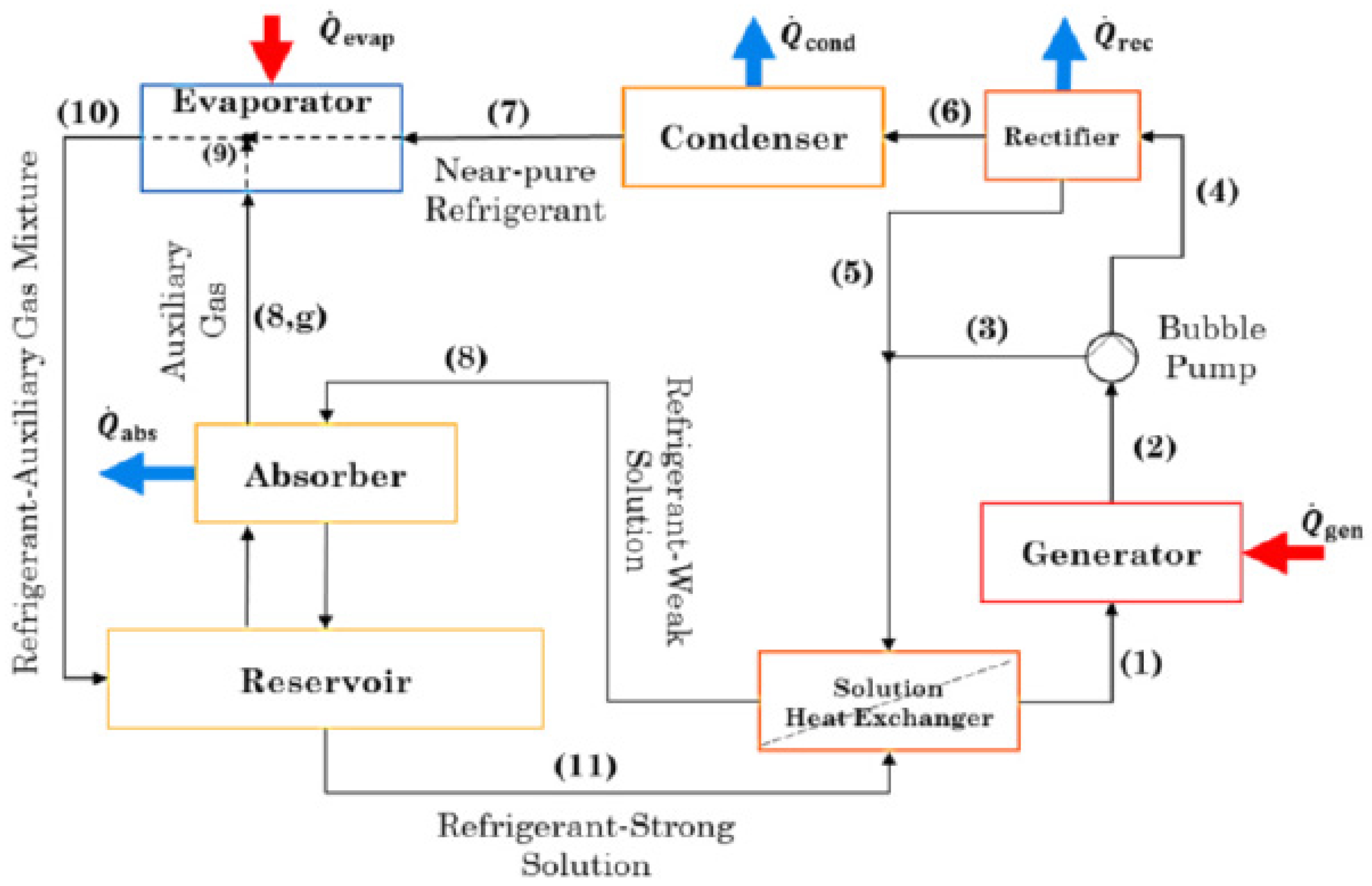
2.1. Diffusion–Absorption Refrigeration (DAR) Cycle

According to several sources [12,27,31,33,46], Von-Platen and Munters patented diffusion–absorption refrigeration (DAR), as a single-pressure refrigeration cycle, in the 1920s.
To illustrate the principle of DAR, Figure 1 below takes up the work of Harraz et al. [27], which shows the key processes of a DAR system with the application of ammonia–water and hydrogen as gas auxiliaries. Thus, the working principle of the diagram in Figure 1 is as follows [27]: a refrigerant-rich solution (1) is heated in the generator with ( Q ˙ g e n ) and it boils (2). Then, the refrigerant bubbles are rising and lift the solution through the bubble-pump’s inner tube. When exiting this tube, there is a separation between the vapour refrigerant (4) and the refrigerant-weak solution (3). When using water or a similar relatively volatile absorbent, before entering the condenser, the ascending vapour refrigerant should pass through a rectifier. In the rectifier, the vapour refrigerant is purified and is emitting heat ( Q ˙ r e c ) to the ambient. Then, in the condenser, the near-pure vapour refrigerant (6) rejects heat ( Q ˙ c o n d ) and exits in a liquid state. The refrigerant-weak solution (3) and reflux liquid (5) flow down the bubble-pump shell. In the next stage, the near-pure refrigerant goes into the evaporator, where is subcooled through a gas heat exchanger and evaporates into the auxiliary gas taking in heat ( Q ˙ e v a p ) from the cold space.
To maintain a single operating pressure, the DAR cycle uses a working fluid composed of a refrigerant, an absorbent, and an auxiliary gas [27,31]. The auxiliary gas is used to maintain a uniform pressure throughout the system and eliminate the use of a compressor [27].

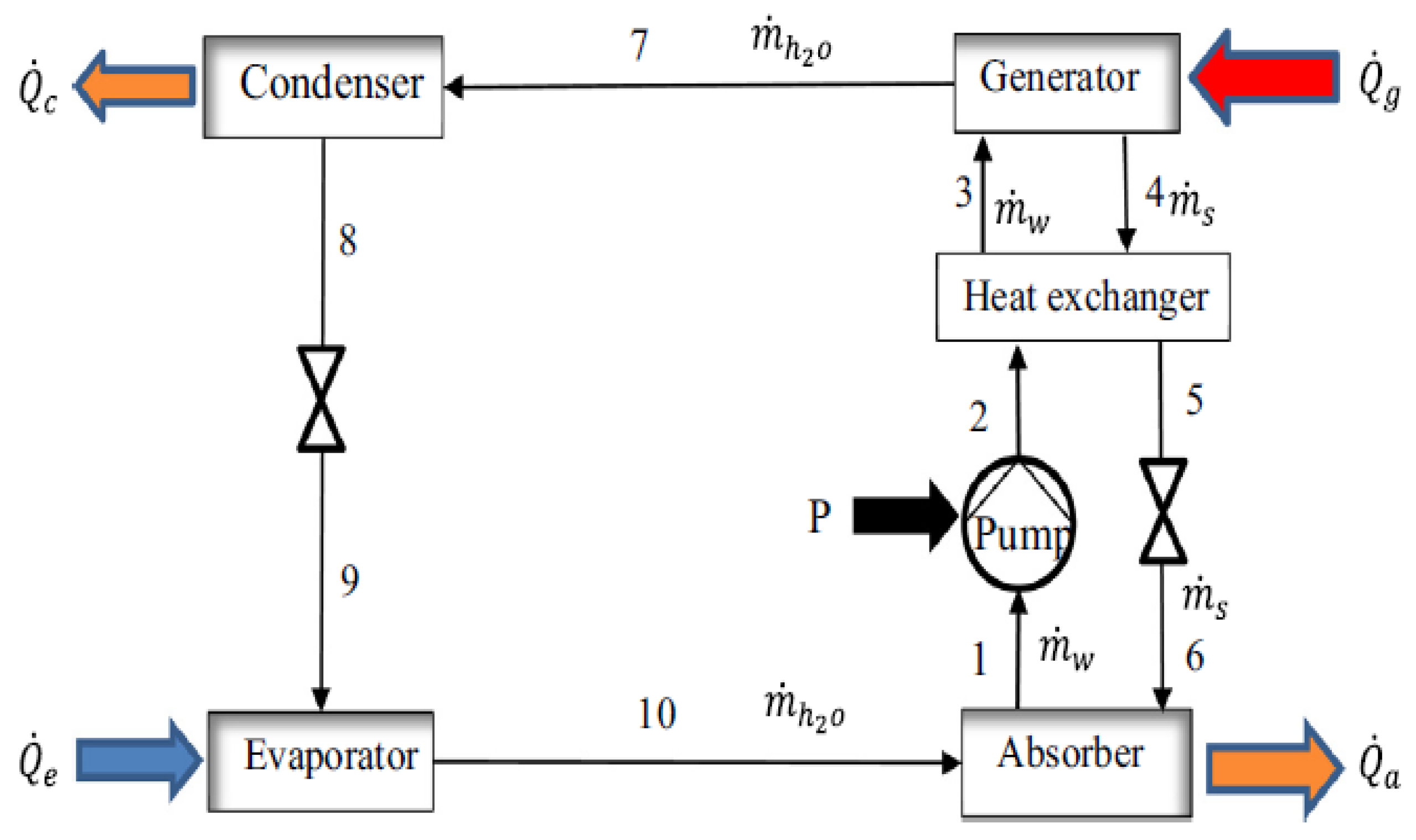
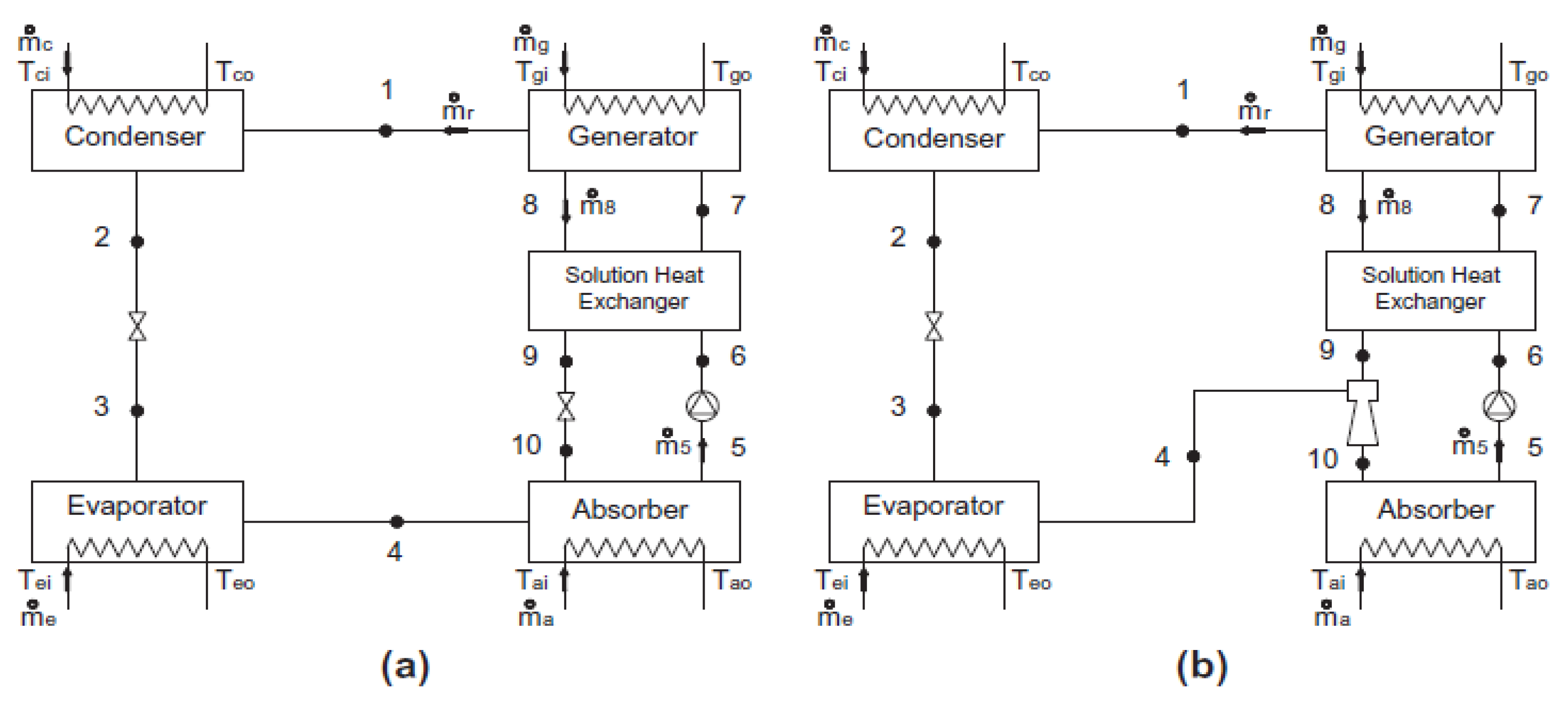
2.2. Dual-Pressure Absorption–Refrigeration (DPAR or ARS) Systems

Dual pressure absorption–refrigeration cycles typically use a binary mixture of working fluids (a refrigerant and an absorbent). According to Salmi et al. [47], the absorption refrigeration system is based on the physical phenomenon of the different boiling points of pure fluids and a mixture of compounds. For Watanabe [48] and Salmi et al. [47], absorption refrigeration systems use regenerative cycles to maintain the evaporator’s pressure difference and cooling effect (Figure 2).
Figure 2 summarizes the principle of a single-effect water-LiBr cycle. The cycle has an absorber, a device in which pure water vapor is absorbed into a solution. When heat is removed from the absorber, the thermodynamic equilibrium is disturbed, and pure water vapor flows out of the evaporator. The latent heat added to the evaporator is absorbed into the solution in the absorber. The weak water-LiBr solution in an absorber is cooled to maintain the process. A portion of the solution is pumped to the generator, where high-temperature heat is added to the solution to separate the pure water from the solution. The water evaporates in the generator and is led to the condenser. The strong water-LiBr solution generated in the generator is returned to the absorber (via an expansion valve) to maintain a constant LiBr concentration. The water evaporated in the generator is condensed to a liquid state in the condenser, and the condensation heat is released. After the condenser, the liquid water flows through the expansion valve to the evaporator, where low-temperature heat is added to evaporate the water (the refrigeration effect). In this case, the water is the refrigerant, and LiBr is absorbent. A recuperative heat exchanger is added between the generator and the absorber to improve the system’s performance [47].
Another configuration of ARS is in Figure 3, whose description is [49]: ABR uses a refrigerant and an absorbent as working fluids. First, the mixture is heated in the generator (QG), separating refrigerant vapor from a remaining absorbent/refrigerant liquid mixture. Then, the refrigerant vapor enters a condenser at high pressure and rejects heat (QC). A rectifier is necessary to complete separation for some working fluid combinations (NH3/H2O or organics). Then, the refrigerant expands in a throttling valve and goes into the evaporator. There, it is cooled by removing heat (QE) from the medium that needs cooling. Then, the heat (QA) is rejected in the absorber. There, it is mixed with the pure refrigerant from the evaporator, and the resulting liquid mixture is pumped back to the generator to complete the cycle.
Figure 3 illustrates the main features of a single-effect ABR process, the most basic cycle configuration. The process uses a mixture of working fluids, including a refrigerant and an absorbent. The heat source supplies heat ( Q ˙ G to the mixture in the generator, where the refrigerant vapor is separated from a remaining liquid absorbent/refrigerant mixture and flows into a high-pressure condenser, where the heat ( Q ˙ C ) is rejected. Separations are performed with a reboiler for some fluids, such as NH3/H2O or organics. The refrigerant is then expanded through a throttle valve and passed to the evaporator, which cools the fluid by removing heat ( Q ˙ E ). The mixture of refrigerant and absorbent that exits the other side of the generator is directed to the absorber, where the heat ( Q ˙ A ) is rejected. There it is mixed with the pure re-coolant from the evaporator, and the resulting liquid mixture is then pumped back into the generator to complete the cycle. Widespread modifications to the basic single-acting ABR arrangement include the addition of a solution (SHX) and a condenser-evaporator heat exchanger (CEHX) because they increase the efficiency of the cycle through internal heat recovery. A significant advantage of ABR over vapor compression refrigeration is that liquid pumping requires only a small fraction of the energy required by compression. Another significant advantage is the possibility of producing cooling from low-temperature heat sources [49].
Garousi Farshi et al. [50], in their work on the analysis of crystallization risk in double-effect absorption refrigeration systems, asserted that absorption–refrigeration systems are an alternative to vapor-compression ones in cooling and refrigeration applications. Maryami and Dehghan [51] have attested that the performance of absorption–refrigeration systems strongly depends on the properties of the pair of active substances and that ammonia–water and water–lithium bromide couples are the pairs of active substances commonly used in heat transfer. Asfand and Bourouis [2] attest that the absorption–refrigeration system (ARS) is a technology capable of utilizing heat directly for cooling purposes and has been considered one of the most widely used technologies for refrigeration and cooling applications since the early stages of refrigeration technology. According to Modi et al. [34], in the last decades, an impressive number of studies have been carried out by many researchers to explore different aspects of the absorption–refrigeration system (ARS). Concerning the fluids used, specific undesirable properties of ammonia (such as toxicity, volatility, and flammability) and lithium bromide (such as corrosion or crystallization of lithium bromide at high temperatures or high condensation) have prompted many researchers to search for new couples of active substances to improve the performance of absorption systems [2]. ARS is becoming more critical because it can be fuelled by renewable energy (like waste heat rejected by the industry, solar, geothermal, biomass, etc.) other than electricity [34].
In general, the ARS has the same structure. However, they differ by adding heat exchangers between the absorber and the generator and/or between the condenser and the evaporator. These additions only aim to increase the system’s performance, as the heat is easily recovered internally [49].

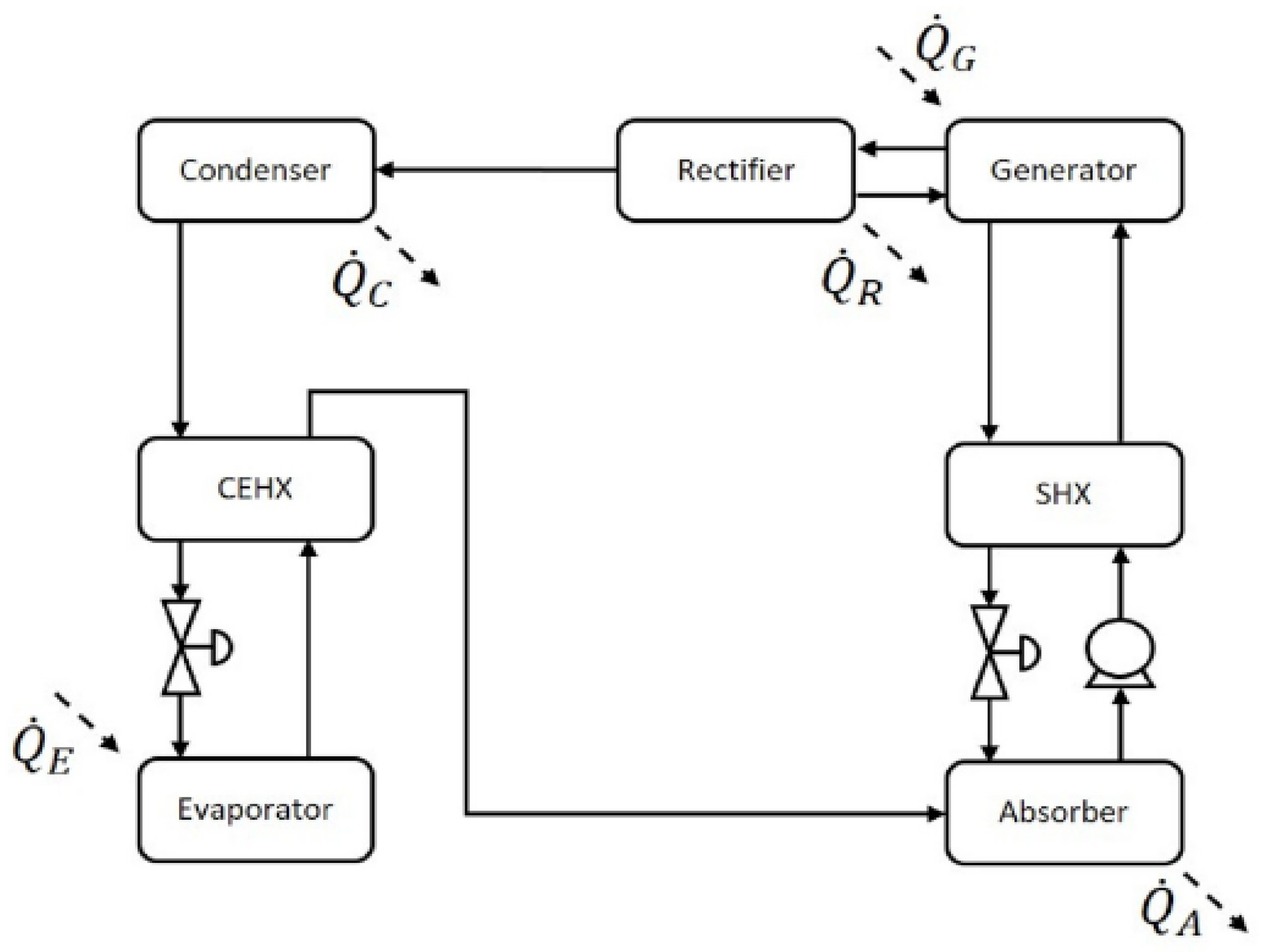
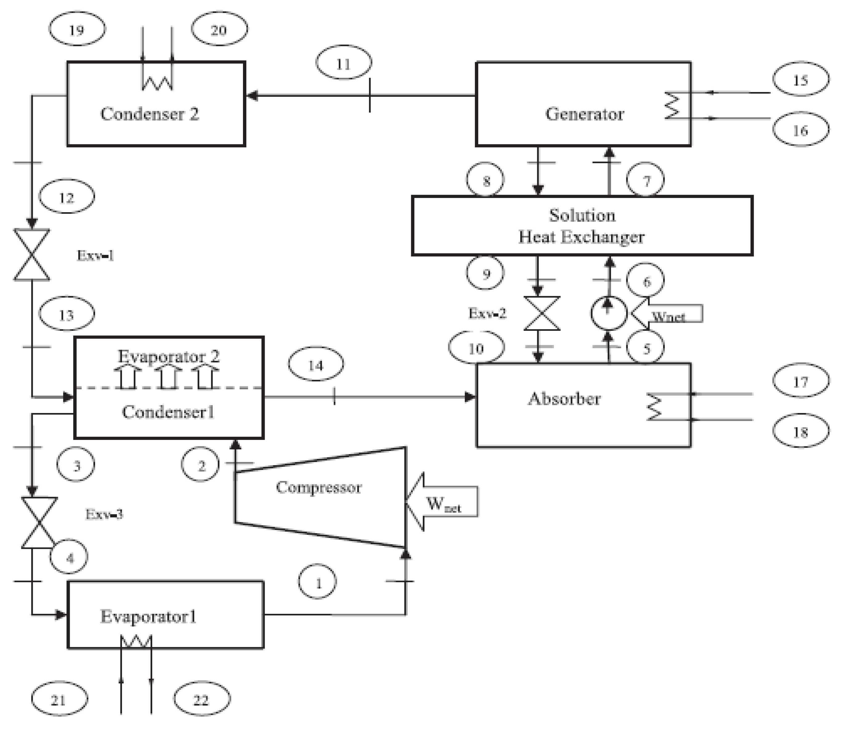
2.3. Hybrid ARS/DAR: Absorption–Compression Refrigeration (ACR) Systems

Currently, several projects use the hybrid (absorption–compression) system. This system generally operates at three pressure levels; the first pressure level concerns the refrigerant vapor leaving the evaporator. The intermediate pressure occurs after the isentropic compression of the refrigerant vapor. The fluid has the same pressure in the absorber. The condenser and generator operate at the third pressure level, the condensing pressure [32].
Figure 4 illustrates the general principle of a compression–absorption cascade refrigeration cycle. Cimsit et al. [52] distinguished two regions, the first is for vapor compression, where R-134a is used as the fluid, and the second is for absorption, which uses LiBr-H2O as the fluid. The cycle description in Figure 4 below is given in [52,53].
Figure 4 represents the general scheme of a cascade compression–absorption cycle, subdivided into two sections: vapor compression, which uses R-134a, and absorption, which uses LiBr-H2O as a refrigerant. In this cycle, a pump draws the weak LiBr solution from the absorber and forces it through a solution heat exchanger. Then, the high-pressure cooled mixture exits the exchanger and flows through the generator. After absorbing the heat applied to the generator, the water in the solution is driven out. Later, the strong LiBr solution exiting the generator undergoes a pressure drop as it passes through a valve. Then, the solution passes to the absorber. To improve the performance of the cycle by increasing the temperature in the state (6) and decreasing the temperature in the state (9), internal heating of the exchanger is used to recover the energy from the strong solution to the weak solution. After condensation by heat rejection into the ambient air, the cooling medium (water) leaves the condenser as a saturated liquid. The pressure of this flow is then reduced by the expansion valve and directed to the evaporator, which absorbs the heat rejected in the condenser from the vapor compression section and evaporates. This vapor then passes through the absorber and is absorbed by a hot solution.
On the other hand, the compressor increases the pressure of the refrigerant in the vapor compression section, and the refrigerant is sent to the condenser. After condensation, the pressure of the refrigerant drops as it passes through the de-tenser. Then the refrigerant is directed to the evaporator. Additionally, the cycle starts again [52].
He et al. [54] sought to make the conventional solar absorption–compression cascade refrigeration (SA-CCR) system efficient by an integrated air-cooled vapor compression refrigeration (ACR) cycle. The ACR cycle comprises two subsystems, a solar-powered single-effect absorption refrigeration (SSAR) and an electrically-powered dual-source vapor compression refrigeration (EDCR). The authors claim significant improvements. The efficiency and time of use of solar energy are dramatically improved and extended, respectively. The cooling/heating demand is always met by coupling an ACR cycle to the EDCR subsystem.
Peng et al. [55] proposed a hybrid absorption–compression cooling system with parallel subcooling and cooling to solve the system’s small-scale heat source versus large heat consumption. Chen et al. [56] proposed an absorption/absorption–compression refrigeration system with a wide operating range, aiming to improve the absorption–refrigeration system’s thermal energy utilization performance. They state that the absorption/absorption–compression refrigeration system offers a promising way to effectively utilize heat sources with a significant temperature change or multiple heat sources with different temperatures. Asensio-Delgado et al. [22], in their analysis of hybrid compression absorption refrigeration using low-GWP, HFC, or HFO/ionic liquid working pairs, showed that CA-ARS performs better even at lower generator temperatures.

2.4. Ejector–Absorption Refrigeration (EAR) Cycle and Other Hybrid Cycles

The advantage of the absorption system is that it can produce cold with a low-temperature energy source. In contrast, using an ejector system increases the performance of the refrigeration machine. In the literature, there are works on refrigerating machines equipped with an ejector. Vereda et al. [57] presented a numerical model of an ejector-absorption refrigerator operating in a steady state. They evaluate the influence of ejector geometry on cycle performance and determine the heat source’s temperature range in which a practical ejector should be used in the absorption cycle. In a cycle equipped with an ejector (see Figure 5), the role of the ejector is to entrain the refrigerant vapor from the evaporator to increase the pressure of the absorber without any additional energy consumption [57]. Dennis et Garzoli [58] use a variable geometry ejector with the cold store to achieve a high solar fraction for solar cooling. They reported that using an ejector increases system efficiency while avoiding the investment cost of acquisition of a large surface area of solar collector. Van Nguyen et al. [59] examined the influence of a variable geometry ejector on a small-scale solar air conditioning system’s performance, aiming to improve the operation of the fixed ejector. Figure 5a shows an arrangement of the conventional single-effect absorption refrigeration cycle, and Figure 5b depicts an arrangement of the ejector–absorption refrigeration cycle. The difference between the diagrams in Figure 5a,b is that a liquid/vapor ejector is located at the inlet of the absorber, replacing the solution expander (9–10). In Figure 5b, the ejector draws the refrigerant vapor from the evaporator (4), entraining it and mixing with it and consequently increasing the pressure of the absorber compared to the pressure of the evaporator thanks to a two-phase diffuser located at its outlet. The details of the cycle of Figure 5 are given in [57].
Fitó et al. [60] conducted a simulation study on the floor-coupled absorption refrigeration system coupled to a thermochemical process by sharing the same condenser, evaporator, and refrigerant. It was found that the COP of the system increased when the two pairs of solutions, namely the NH3/LiNO3 and NH3/BaCl2 pairs, were combined.

2.5. Comparison between DAR, DPAR or ARS, ACR, and EAR

This section gives a brief comparison between the different cycles above (see Table 1).
It is essential to point out that although ARS can operate at low heat source temperatures, they still suffer from temperature limitations, a significant obstacle to obtaining optimal COPs. Hence the importance of optimizing ARS technology (see [62]).

3. Models for Estimating Useful Energy for the System

There are studies in the literature based on clean energy (solar, geothermal, etc.) use and others that combine several clean and/or residual energy sources [63,64,65,66,67,68,69,70,71,72,73,74,75,76,77,78,79,80,81,82,83,84,85,86,87,88,89,90,91,92,93,94]. This section addresses and discusses only solar, geothermal, and waste gas heat sources.

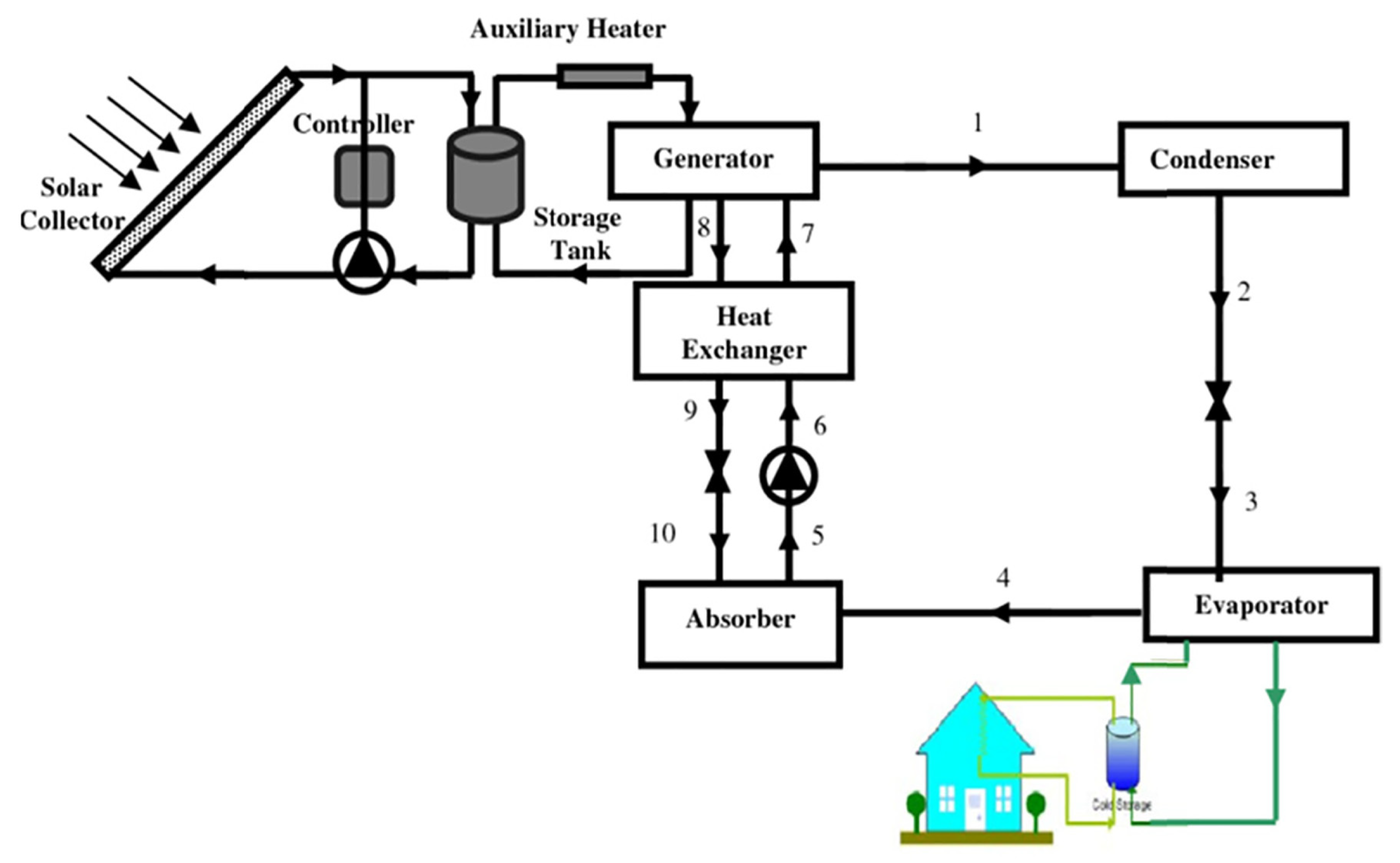
3.1. ARS/DAR Using Solar Energy Sources

3.1.1. Background

According to Siddiqui and Said [14], solar energy is a natural, available, and environmentally friendly source and presents a substantial potential renewable energy source. Solar energy can either be used directly, from the collector to the generator, passed through a water storage tank equipped with phase change materials, or even converted into electrical energy before use. Wang [10] studied the operating characteristics of an absorption–diffusion refrigerating machine using solar energy as the energy source. The solar water heater is an internal concentrator solar collector with a hot water tank. LiNO3-NH3-He was used as the working fluid, and an adiabatic sputter absorber with a plate solution cooler improved mass and heat transfer. An evaporation temperature of −13 °C, a cooling capacity of 1.9 W, and a COP of 1.156 were found. The solar energy source provided a temperature of 92.7 °C. Al-Hamed and Dincer [95] developed and evaluated the performance of a thermodynamic model of a combined ejector–absorption refrigeration cycle powered by a solar concentrator and a geothermal well. This work led to a COP value of 1.164 for a generator temperature of 98.7 °C. Dhindsa [43] discussed solar steam refrigeration systems and various techniques to improve their performance (see Figure 6).
Karamangil et al. [4] simulated a solar absorption refrigeration system and studied the effects of various system parameters, such as temperature and solution efficiency. This work showed that increased operating temperature increased the generator and evaporator performances. Zeiny et al. [96] used solar evaporation via nanofluids to significantly improve the photo-thermal conversion efficiency of direct absorption solar collectors. They concluded that the system’s efficiency increases when the nanofluid concentration is increased in the collection tubes exposed to direct sunlight. Finally, the study on solar absorption refrigeration systems working all day with a heat pump system proposed by Li et al. [97] highlighted the advantage of using a solar collector equipped with a heat storage system using phase change materials (PCM) and a heat pump. This system allowed for a cooling capacity of 9 kW throughout the day.

3.1.2. Models Proposed in the Literature

Several authors have worked on absorption refrigeration machines, focusing on the energy source [47,52,52,55,98,99,100,101,102,103,104,105,106,107,108,109,110,111,112,113,114]. Thus, to calculate the energy source, several configurations are possible: the use of solar collectors, the use of engine exhaust gases, etc. Furthermore, some authors have proposed methods and techniques to calculate the power to be transferred to the generator of solar refrigeration machines, in particular Li et al. [97]. The latter proposed the following (in two configurations): the solar collector and the energy storage system. The energy collected in the solar collector is modeled as follows:
Q ˙ u c A c o l = I s × η s c s
where Q ˙ u c is the effective output power of the collector (W), A c o l the illuminated surface of the collector (m2), I s the solar intensity or irradiation (W/m2) and η s c s the efficiency of the collector.
η s c s = M N t 1 s c s t a I s
With t a the ambient temperature (°C), t 1 s c s the inlet water temperature to the collector (°C), M and N are inherent characteristics of the collector. As an order of magnitude, M = 0.74 and N = 5.0 [97].
As for the energy storage system, Li et al. [97] model it by the following relations:
Q ˙ i n = Q ˙ u c Q ˙ o u t = Q ˙ g e n Q ˙ i n Q ˙ o u t
where Q ˙ i n is the amount of heat entering the energy storage system (W), Q ˙ o u t the amount of heat leaving the energy storage system (W) and Q ˙ g e n is the power transferred to the generator (W).
Pilatowsky et al. [115] modeled the storage tank using an average storage tank temperature ( T S T ), according to the following energy equation:
m C p f d T S T d t = Q ˙ i n + Q ˙ S + Q ˙ E N V
where Q ˙ i n is the rate of energy input to the storage tank from the hot fluid flow (W), Q ˙ S is the rate at which sensible energy is withdrawn from the tank to feed the load (W) and Q ˙ E N V is the rate of energy loss from the tank to the environment (W). Their expressions are given below:
Q ˙ i n = m ˙ h f C h f T i n T S T Q ˙ S = m ˙ L O C h f T S T T a Q ˙ E N V = U L A S T T S T T a
With m ˙ h f the mass flow rate of the hot fluid (kg/s), m ˙ L O the mass flow rate of the fluid feeding the load (kg/s), U L the overall heat transfer loss coefficient (W/m2/°C), C h f the heat capacity of the hot fluid (J/kg/°C) and A S T the exchange surface between the tank and the environment (m2).
The work of Pilatowsky et al. [115] established the following relationship:
Q ˙ g e n = m C p f d T S T d t
Boopathi Raja and Shanmugam [116] presented the relationships to calculate the instantaneous values of the solar thermal plant during the day as:
Q ˙ t = A c o l × G t Q ˙ c o l = m ˙ f c o l C p f c o l t 0 c o l t i c o l Q ˙ i t a n k = m ˙ × C p t 0 t a n k t i t a n k
The collector efficiency and the heat transfer rate of the generator given by Boopathi Raja and Shanmugam [116] are as follows:
η c o l = Q ˙ c o l / Q ˙ t
Q ˙ g e n = m ˙ × C p t i g t o g
where A c o l is the illuminated area of the collector (m2), G t solar intensity or irradiation (W/m2), t 0 t a n k the storage tank outlet temperature (°C) and t i t a n k the inlet temperature of the storage tank (°C).
Al-Hamed and Dincer [95] and Wageiallah Mohammed and Yanling [117] calculated the heat source’s power by the installation’s heat balance. Nikbakhti et al. [118] have modeled the energy balance of the solar collector by the following relationship:
m C p s c d T s c d t = η s c A s c I s + m ˙ s c C p h w T s c , i n T s c , o u t
where the left-hand side represents the solar collector’s internal energy change, the right-hand side’s first term indicates the amount of energy received from solar radiation, and the second term represents the heat gained by the heat transfer fluid.
The hot water outlet temperature of the solar collector and the thermal efficiency of the solar collector are estimated by the following relationships, respectively:
T s c , o u t = T s c + T s c , i n T s c e x p U s c A s c m ˙ s c C p h w
η s c = Q ˙ u t i l e Q ˙ s o l a i r e = m ˙ s c C p h w T s c , o u t T s c , i n A s c I s
As for the temperature of the hot water in the generator, Nikbakhti et al. [118] have modeled it by the following expression:
T h w , o u t , g e n = T g e n + T h w , i n T g e n e x p U g e n A g e n m ˙ h w C p h w
where U is the overall heat transfer coefficient (W/m2/K), A the section (m2), and the index h w symbolizes hot water.
He et al. [54] modeled the solar part similarly to Li et al. [97], but they opted for different values of N and M (M = 0.80 and N = 3.50).
Among the models above, the models presented by Li et al. [97], Pilatowsky et al. [115], Boopathi Raja and Shanmugam [116], and He et al. [54] are global and complete. They consider energy collection at the collector, its storage, and its use at the generator level. At the same time, authors give correlations that only consider the energy collected and its use or stored energy and its use. Although both solar electric and solar thermal systems can produce refrigeration, solar thermal absorption systems are found to be comparatively more efficient. Therefore, such systems are more suitable for applications in remote areas where conventional power sources are unavailable or expensive. They are also more suitable due to using environmentally friendly working fluids as refrigerants instead of chlorofluorocarbons [14].

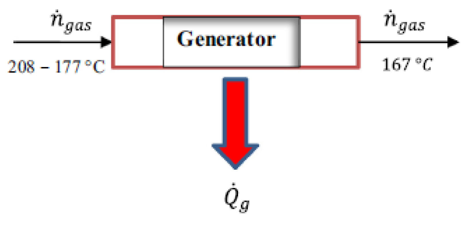
3.2. ARS/DAR Using Waste Gas or Waste Heat as Energy Sources

3.2.1. Background

The heat contained in residual gases is increasingly used in industry. Many studies on absorption machines use energy from industrial waste gases or internal combustion engines. Adjibade et al. [3] experimentally studied H2O-NH3-H2 diffusion absorption refrigeration under two energy sources: electrical energy and internal combustion engine (ICE) exhaust gas. To evaluate the behavior of the system’s components for each energy source, the authors resort to the dynamic method, which reveals that the system using the exhaust gases of the ICE presented better performances compared to the case of electric energy. Manzela et al. [119] asserted that internal combustion engines were potential energy sources for absorption refrigeration systems. Kaewpradub et al. [120] have developed a single-effect absorption refrigeration system that uses LiBr-H2O as the solution and engine exhaust as the energy source. Several parameters were considered to evaluate the performance of the machine: the rotational speed of the engine, the opening position of the expansion valve (both at the separating outlet and the condenser outlet), the temperature of the refrigerant at the outlet of the condenser, and the flow rate of LiBr-water solution. Jianbo et al. [121] proposed a cascade absorption–compression refrigeration machine that utilizes waste heat from the internal combustion engine of vehicles, where the exhaust gases and the engine coolants heat the working fluids of the high-pressure generator and the low-pressure generator. Novella et al. [98] proposed a thermodynamic model to analyze an absorption refrigeration cycle used to cool the intake air temperature in an internal combustion engine, using engine exhaust gases as a heat source. They showed that it is possible to lower the intake airflow temperature to less than 5 °C by using the residual thermal energy in the exhaust gases.
Aly et al. [99] work on the thermal performance of a diffusion absorption refrigerator powered by the diesel engine exhaust waste heat as an energy source, concluding that excessive heat harms the overall system performance. Yuan et al. [122] presented theoretical and experimental studies of a marine engine exhaust heat recovery system based on refrigeration and freezing before desalination. While the first system is dedicated to refrigeration, the desalination system uses seawater as a phase change energy storage material. A value of 16% was found as the coefficient of performance. Meanwhile, the system’s total cooling capacity varied from 6.1 kW to 9.9 kW.
Ziapour and Tavakoli [100] developed a thermodynamic model of a diffusion absorption refrigeration heat pipe cycle using a thermosiphon as the energy source. The authors carried out the exergy analysis of the cycles based on the second law of thermodynamics, intending to calculate the exergy destruction in the process. As a result, high COP values were achieved with low thermosyphon temperatures, low weak solution (lean mix) concentrations, and high evaporator temperatures.
Nikbakhti et al. [118] developed an adsorption-absorption integrated refrigeration system powered by low-quality heat sources. As such, they solve the problems encountered by single-effect absorption systems (drop in performance when the heat source temperature drops below 85 °C) and single-effect double-lift absorption system problems (crystallization and corrosion). This experiment gave the following results: a heat source temperature of 60 °C, a cooling capacity of 13.7 kW, and a COP of 0.4.
Soliman et al. [123] designed an absorption cycle using phase change materials (PCM) fueled by automotive exhaust gases. This cycle features a counter plate generator with rectangular ribs and split cells, filled with multiple MCPs to store exhaust gas energy throughout the charging process in the diesel engine to run the cycle absorption. The authors claim that the exhaust energy was not high enough to run the system, hence the use of PCMs, which provide additional energy to run the cycle up to the melting temperature of the MCP type. They found COP values of 0.767 to 0.778 for engine speeds ranging from 1500 to 2000 rpm.
Mbikan and Al-Shemmeri [124] developed a computer model of a water-ammonia absorption refrigeration system powered by energy produced by burning biomass.

3.2.2. Models Proposed in the Literature

As for calculating the generator’s power output, in the case of absorption chillers using exhaust gas as an energy source, the literature gives a list of models, some of which are close. For example, Aly et al. [99], Adjibade et al. [3], and Manzela et al. [119] have modeled the instantaneous power of the heat source by the following relationship:
Q ˙ g e n = m ˙ e x h h e x h , i n h e x h , o u t Q ˙ i n s
where m ˙ e x h is the engine exhaust gas mass flow rate (kg/s), h e x h , i n the specific enthalpy of the engine exhaust gas at the inlet to the steam generator (J/kg), h e x h , o u t the specific enthalpy of the engine exhaust gas at the outlet of the steam generator, and Q ˙ i n s the heat transfer from the engine exhaust gases to the environment through the insulated wall of the steam generator (W).
The following expression gives the engine exhaust gas mass flow rate:
m ˙ e x h = ρ F γ ˙ F 1 A / F
With ρ F the density of the fuel (kg/m3), γ ˙ F the volume flow rate of the fuel (m3/s), A the airflow (kg/s), and F fuel flow (kg/s). The report A / F is nothing more than the air/fuel ratio.
Aly et al. [99] modeled the engine exhaust mass flow as follows:
m ˙ e x h = ρ e x h γ ˙ e x h
where ρ e x h the density of the exhaust gases (kg/m3) and γ ˙ e x h the exhaust gas volume flow (m3/s).
Manzela et al. [119] calculated the enthalpy change of the exhaust gases by the following expression:
h i n h o u t = i = 1 j y i h i n h o u t i
where y i , h i n and h o u t are the mass fraction, the input enthalpy (kJ/kg) and the output enthalpy (kJ/kg) respectively of the exhaust gas components CO, CO2, HC, H2O, O2 and N2.
To solve the above equations, Manzela et al. [119] measured the concentration of the exhaust gas components experimentally, and the enthalpy values were taken from thermodynamic tables based on the exhaust gas temperature.
Novella et al. [98], Jianbo et al. [121], Agostini et al. [125], Karamangil et al. [4], Ersöz [126], Taieb et al. [127], Yuan et al. [122], Ziapour and Tavakoli [100], and Ouadha and El-Gotni [128] calculated the power of the heat source by the heat balance of the installation. Yildiz [102] gave the following equation:
Q ˙ g e n = W ˙ e l e c t η e l e c t Q ˙ g e n = m F H u η c b F t
where W ˙ e l e c t is the power consumption (W), η e l e c t electrical efficiency (assumed to be 0.99), m F fuel consumption (kg), t is the duration of the test (s), Hu is the net calorific value (J/kg) and η c b F the combustion efficiency of the fuel (assumed to be 0.90).
Mansouri et al. [129] proposed to calculate Q ˙ g e n directly from the coefficient of performance relationship, indirectly deducing the cooling capacity from the measured temperatures and appropriate heat transfer models in a multi-step procedure. Salmi et al. [47] modeled the heat recovery process using the diagram in Figure 7, which translates mathematically into the following expression:
Q ˙ g = Q ˙ g e n = i = 1 j n ˙ g a s h i n h o u t
where n ˙ g a s is the molar flow (mole/kg) for each substance in the exhaust gas. The enthalpies h i n and h o u t (J/mole) are for each flue gas species at the inlet temperature (taken from the data) and at the outlet temperature (167 °C).

3.3. ARS/DAR Using Geothermal Resources as Energy Sources

There is very little work in the literature on absorption chillers using geothermal energy as an energy source, which gives the methods used to calculate the useful power of the generator. Wu et al. [130] developed a model to evaluate and optimize the performance of a new combined geothermal cooling and power system integrating an organic flash cycle with an ammonia–water absorption refrigeration cycle. They calculated the power supplied to the generator using the heat balance of the system. Salhi et al. [104] studied the possibility of using geothermal energy (whose temperature is between 60 and 94 °C) as an energy source that can power the combined compression–absorption refrigeration system. The COP values found were between 0.184 and 0.595. Salhi et al. [104] estimated the heat supplied to the generator in the absorption system, derived from a geothermal water source, by the following relationship:
Q ˙ g e n = m ˙ f × C p f T w T g Δ T p n
where Δ T p n is the temperature difference between the generator and the evaporator pinch-off temperature and is set at 5 K, m ˙ f the flow rate of the geothermal water (kg/s), C p f the specific heat of the geothermal water flow (J/kg/K), T w the temperature of the geothermal well (K) and T g the generator temperature (K).
Tetemke et al. [131] analyzed a geothermal-powered vapor absorption refrigeration system and modeled the power supplied to the generator by the following relationship:
Q ˙ g e n = T H T a t m / 1 h i A i + l n r 0 / r i 2 π k L C + 1 h 0 A 0
where T H is the hot water temperature (K), L C the length of the cylindrical tube (m), r 0 and r i outer and inner radii of the tube, respectively (m), h 0 and h i external and internal convection coefficients of the tube, respectively (W/m2) and k the thermal conductivity of the pipe material (W/m/K). To solve the above equation, it is necessary to know the total length of the tube L C or calculate it, the tube’s material properties, and the tube’s diameter.
Yilmaz and Kaska [132] studied the performance and optimization of a geothermal absorption-assisted hydrogen liquefaction system pre-cooling refrigeration cycle. They estimated the power transferred to the generator by the following expression:
Q ˙ g e n = m ˙ g e o h g e o , i n h g e o , o u t
where m ˙ g e o flow rate of the geothermal fluid (kg/s), h g e o , i n and h g e o , o u t are, respectively, specific input and output enthalpies of the geothermal fluid (J/kg).
The different models mentioned above, as well as other models, are summarised in Table 2.
Considering the work covered in the literature, it would be important to incorporate an energy storage system between the geothermal source and the generator to make the energy supply sustainable during fluctuations.
Equations (1)–(22) and those described in Table 2 are derived from different configurations of energy sources, allowing the operation of diffusion absorption refrigeration machines. In addition, these equations allow the calculation of the heat Q ˙ g e n required to operate the generator, which produces steam through the heat received from a heat source external to the circuit.
In this article, several sources of heat Q ˙ g e n are presented as solar, geothermal, and hot waste gases from thermal engines or industrial processes.

4. Recent Developments and Advancements

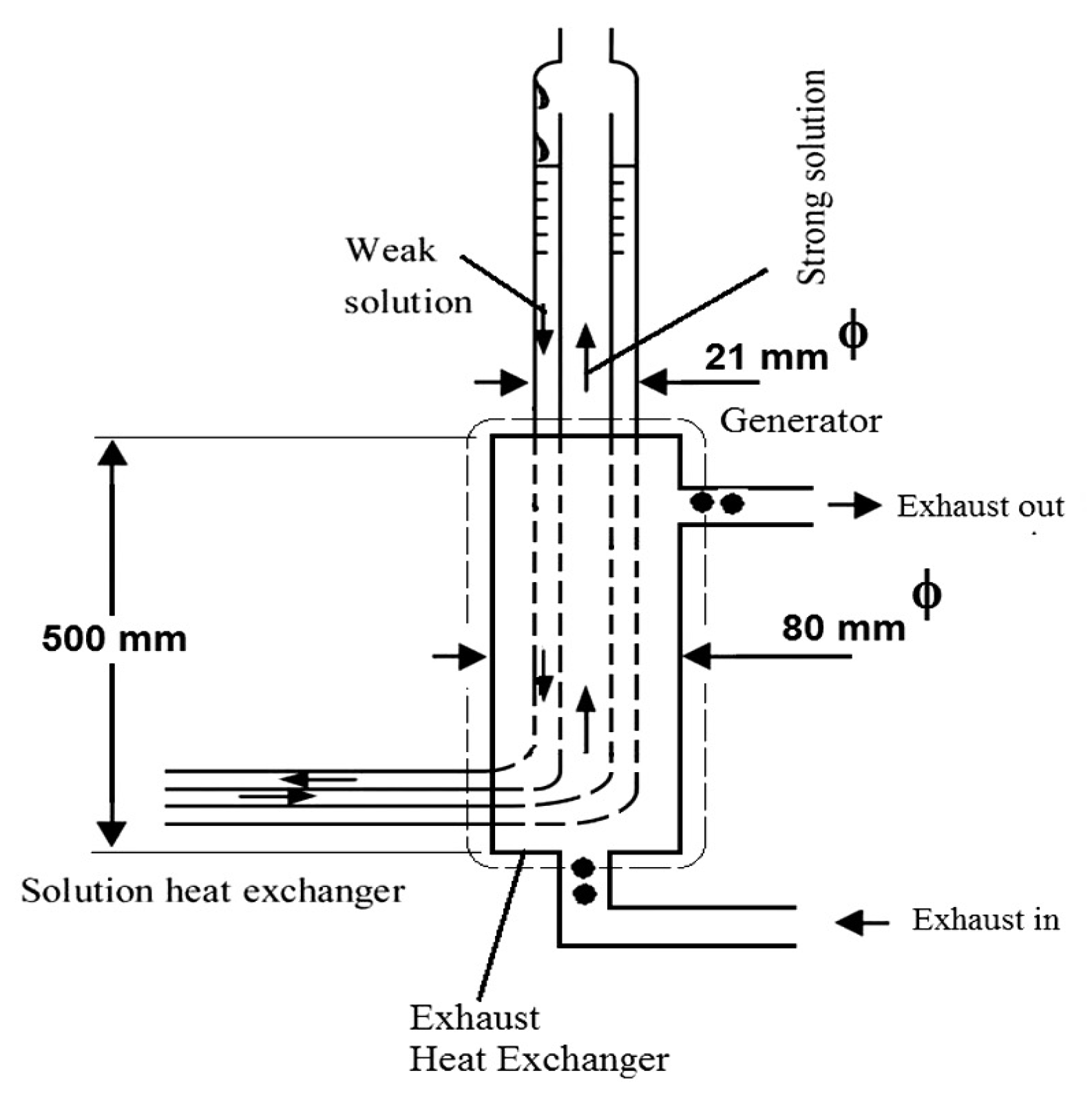
4.1. Design and Technology of Bubble Pumps and/or Generators

The generator is the primary part where the system is supplied with energy. Its location and/or structure are of particular interest because the efficiency of the refrigerating machine depends on it. Several types and designs of generators have been developed in recent years, which differ in how they exchange energy with the strong (or weak) solution. Some generators are coupled to the bubble pump, thus forming a single piece. In this case, we discuss integrating the bubble pump into the generator. Bubble pumps have been used in VARS (Vapour Absorption Refrigeration System) for an ammonia-water working fluid since the 1920s, using the Platen et Munters cycle [46], known as the diffusion absorption refrigeration cycle (DAR) or Einstein cycle (1928) [142].
Generally, the bubble pump aims to pump the solution from the lower to the system’s upper level [12]. Thus, in the literature, several models and designs have been developed. Jianbo et al. [121] used a multi-wire coil tube heat exchanger with a separator as a high-pressure generator to connect the exhaust and absorption refrigeration systems. Aly et al. [99] presented the configuration of Figure 8, a heat exchanger used to transfer heat between the exhaust gases coming from the engine and the strong solution entering the generator. It is designed as a shell and shell heat exchanger with a 50 cm length and 8 cm diameter, while the shell is made of 1 mm thick low carbon steel. Adjibade et al. [3] proposed an exchange similar to that of Aly et al. [99] (see Figure 9).
Figure 8 illustrates the heat supply to the generator through a heat exchanger. The heat exchanger transfers heat between the exhaust gases from the engine and the strong solution entering the generator. This heat exchanger is designed as a shell and tube heat exchanger with a shell length of 50 cm and a diameter of 8 cm. The shell is made of 1 mm thick low-carbon steel. Thermocouples measure the temperatures of the exhaust gases entering and leaving the heat exchanger and several points inside the refrigerator [99].
Figure 9 represents the connection diagram of the refrigerator with the energy source, the exhaust pipe. The hot gases entering the generator heat the H2O-NH3-H2 mixture before being returned to the condenser via the bubble pump. The outlet of the gases used to heat the mixture is also shown.
Rodríguez-Muñoz and Belman-Flores [143] presented and discussed some types of bubble pump (Figure 10 and Figure 11). Figure 10 shows a multi-tube bubble pump used in the work of Vicatos and Bannett [144]. The advantage of this type of pump is that it does not limit the fluid flow speed and allows an increased cooling capacity by up to 13% of its lower activation temperature compared to a pump with a single tube.
The authors presented the three generator/bubble pump configurations: in the first configuration (Figure 11a), the generator and the bubble pump are completely separated, the heat is directly supplied to the rich solution without heat transfer to the poor solution, the two tubes are insulated to avoid losses. In the second configuration (Figure 11b), heat is supplied to the scope solution by heat transfer from the bubble pump to the outer tube. The outer tube is isolated from its environment. In the third configuration, the two tubes are fully attached (Figure 11c), and heat is supplied to the rich solution by the lean solution. It also separates the refrigerant from the lean solution, which flows from the lower part of the pump (configuration used in commercial equipment) [143].
Jianbo et al. [121] presented two generators (see Figure 12): low-pressure and high-pressure. In the first configuration (low-pressure generator), the water from the internal combustion engine jacket enters the heat exchanger and heats the solution. The higher concentration of the NH3-H2O mixture is sprayed on the outer surface of the coiled tube and heated by the jacket water. Thus, we obtain the refrigerant vapor on the outer surface of the coiled tube. This part represents the multi-wire serpentine tube heat exchanger with a separator intended to connect the exhaust and absorption refrigeration systems and is used as a high-pressure generator.
In the second configuration (high pressure), the generator is a tubular multiwire coil exchanger with a separator. Its operation principle is as follows: the exhaust gases will heat the fluids flowing inside the coiled tubes. As a result, the strong solution of the NH3-H2O mixture changes from a single-phase to a two-phase (vapor-liquid) state, and the vapor flows into the separator with the riser tubes, effectively decreasing the superheat of the vapor and lowering the thermal load of the generator (high pressure) and the condenser. After the vapor-liquid two-phase fluids are heated, they flow into a separator, where vapor and solution are separated. According to Jianbo et al. [121], the exchanger has the advantage of direct heat exchange between the working fluids and the exhaust gases. Moreover, it does not need a second heat exchange system. Figure 13 shows a system equipped with a bubble pump, operating as a thermally driven pump, containing a vertical lift tube connected to the generator and the separator [142].
Figure 13 also shows how the heat input from the generator is used to vaporize and separate the refrigerant from the liquid mixture and pump the solution through the bubble pump. Heat is supplied to the generator in this configuration, and vapors are formed in the liquid. The presence of a bubble pump above the generator allows creating the vapor bubbles by evaporation. This increases the buoyancy of the liquid and makes the liquid rise through the lifting tube in two-phase flow conditions [142]. The temperature of the weak solution leaving the generator is the highest temperature of the working fluid. In the SHX, the hot weak solution leaving the generator gives energy to the rich solution in the absorber, which has a lower temperature. The weak solution (return path) absorbs the refrigerant vapors from the generator into the absorber.
The boiler-bubble pump design of Figure 11c, presented by Ben Ezzine et al. [12], has similarities with Rodríguez-Muñoz and Belman-Flores [143].
The machine in Figure 14 consists of an absorber, an evaporator, a gas and solution heat exchanger, a rectifier, a condenser, and a generator combining the boiler and the bubble pump. It relies on a bubble pump to pump the solution from the lower to the upper level. The rich solution exiting the absorber flows to the heated generator, causing the evaporation of a part of the refrigerant (R124). The resulting vapor bubbles rise in the tube. Due to the small diameter of the pump tube, each bubble acts like a gas piston and lifts a small plug of liquid upwards. The weak solution flows back down to the absorber via an SHX solution heat exchanger. The vapor leaving the generator contains a residual absorbent (DMAC) that is removed by condensation in the rectifier. The R124 vapor (1) is then condensed in the air-cooled condenser, and the liquid refrigerant is introduced into the evaporator. As this evaporator is charged with hydrogen, the partial pressure of the R124 liquid decreases rapidly and, as a result, it starts to evaporate at low temperatures producing useful cold. The resulting heavy R124/hydrogen vapor mixture flows from the evaporator and falls into the air-cooled absorber. The weak solution absorbs the refrigerant from the vapor phase forming an R124-rich solution. The residual hydrogen-R124 gas mixture flows back to the evaporator, and the rich solution flows down to the generator via the solution heat exchanger, where it is preheated. The DAR is a self-circulating system. The circulation is solely due to the differences in gravity and density of the working fluid [12].
Belman-Flores et al. [145] presented an analytical model of the bubble pump in a commercial diffusion/absorption refrigerator, in which the refrigeration system’s cooling capacity and the coefficient of performance are evaluated. They depend on geometric and operational parameters such as heat contribution, diameter ratio, and the bubble tube. In the technologies proposed by Srikhirin [13] and Belman-Flores et al. [145], the weak solution enters through the absorber without being in contact with the mixture passing through the generator. Therefore, they are similar to Rodríguez-Muñoz and Belman-Flores [143] configuration of Figure 11a.
Figure 15 shows a schematic diagram of this system. An auxiliary gas is charged into the evaporator and absorber. Therefore, this system has no pressure differential, and the bubble pump can be used. The cooling effect is achieved based on the partial pressure principle. Since the auxiliary gas is charged into the evaporator and absorber, the partial pressure of ammonia in the evaporator and absorber is kept low enough to correspond to the required temperature inside the evaporator. The auxiliary gas must be non-condensable such as hydrogen or helium [13].
In general, the DAR system uses hydrogen as an auxiliary gas, although hydrogen can be dangerous in the event of a leak. In this configuration, helium is an alternative auxiliary gas introduced to replace hydrogen.
The main feature of a bubble pump is its ability to change the fluid’s flow phase. When a bubble pump is used in VARS, the refrigeration cycle is almost a single-pressure system because there is a minimal pressure difference between the condenser and the evaporator due to flow friction and gravity [142]. It is different in the case of hybrid machines, particularly those equipped with an ejector, which increases the pressure from the evaporator to the absorber. It is also different from hybrid machines equipped with a compressor. Belman-Flores et al. [145] reported that the main advantage of DAR is that it does not require a mechanical/electrical pump or compressor to generate the pressure increase as in the case of conventional refrigeration cycles. Given the abovementioned considerations, it is clear that trade-offs must be made between energy performance, pressure level, energy consumption, and investment cost.

4.2. Influence of Energy Source on System Parameters

The energy source of a diffusion absorption refrigeration machine greatly influences the system parameters (temperature, pressure, etc.). Adjibade et al. [3] stated that the temperature of the generator greatly influences that of the evaporator and the ammonia vaporization. The authors reveal that the temperature of the evaporator negatively correlates with the temperature of the generator. In contrast, one of the condenser/absorber has a positive correlation with the temperature of the generator. According to Kaewpradub et al. [120], decreasing refrigerant temperature at the condenser outlet increases the cooling load and the COP. They also asserted that the LiBr-water solution’s temperature at the generator outlet increases with the engine speed. Additionally, the cooling load and the COP decrease with the temperature of the coolant at the outlet of the condenser.
The work presented by Manzela et al. [119] showed that the wider the valve opening, the lower the average steady-state temperature reached inside the refrigerator (between 5 and 13 °C), and the lower the COP. This led them to think of a system to control the mass flow of the exhaust gases, which makes it possible to optimize the operation of the absorption refrigeration system. According to Aly et al. [99], excessive exhaust gas temperatures make it difficult for water vapor to condense in the separator and directly impact the refrigeration capacity and the cycle COP. On the other hand, the authors state that optimizing the system component design makes sense since the evaporator and generator dimensions greatly influence the COP. As for Yuan et al. [122], the increase in the generation temperature also implies an increase in the COP. Li et al. [97] asserted that the collector inlet temperature is directly determined by the phase transition temperature (PTT) of the PCM in the heat storage system (HSS) and influences the performance of the solar collector system (SCS) and heat pump system (HPS).
Table 3 shows the key parameters of different models of absorption refrigeration machines found in the literature.

4.3. Current Status, Challenges, and the Future Direction of Technology

This section discusses the different models and designs for modeling the power source of absorption machines power source. Current techniques include the addition of new heat exchangers and designing generators integrating both the boiler and the bubble pump. The diffusion and/or absorption refrigeration machines (ARS, DAR, etc.) are used in many industrial and building sector (tertiary) applications. The scarcity and depletion of fossil fuels (which encourages the use of alternative energies), the management and storage of energy, and the intermittency of renewable resources (solar, for example) are real challenges facing diffusion and/or absorption refrigeration machines. The issue of energy management and storage remains a significant issue that encompasses both the choice of energy sources and the availability of energy at all times. Other challenges faced by absorption machine generators are, among others, energy optimization (recovery, storage, and valorization of waste heat internally, optimization of process control laws, etc.), limitation of the temperature of the heat source used, and the control, the automatic and optimal control of the generator by taking into account all the operating parameters of the process.

4.3.1. Energy Management and Storage—Intermittency of Renewable Resources

Energy management is today one of the main issues directly related to global energy resources. Absorption machines generally use intermittent renewable energy sources, some of which need storage. Thermal energy storage can be an excellent option to mitigate the intermittency of renewables. Hence the need to store them to ensure the long-term operation of absorption machines. There are several types of energy storage. The commonly encountered classification is as follows:
  • Sensible heat storage systems. In these systems, we use the thermal power from the solar collector and raise the temperature of a liquid or a solid (water, thermal oil, molten salt, rock, sand, etc.). Its low cost and low toxicity of materials make this technology widely spread [136,147];
  • Latent heat storage systems. These systems are based on a phase transition of the storage material. A high energy storage density characterizes by using a Phase Change Material (PCM) at a nearly constant temperature [138,148,149,150,151];
  • Thermochemical storage systems. These systems use reversible exothermic/endothermic chemical reactions. They are more complex and expensive but have a high storage density and are compact and efficient [136,152].
Rosiek and Batlles [153] investigated how to find the optimal conditions and operating parameters of the solar system using energy storage tanks. The results show that using two water storage tanks is crucial to maintain the system’s operation with irregular solar radiation. Finally, Luján et al. [136] worked on the influence of different thermal storage capacities and thermal energy consumption strategies in a solar air conditioning system. In this work, the intermittency of solar energy was not problematic because the refrigeration needs were almost synchronized with the hours of sunshine. The main novelty of this article is the introduction of a systematic approach to determine the optimal sizing of a hot thermal storage tank according to the nominal thermal power demands in an adjustable jet-ejector refrigeration system.
Khan et al. [154] have proposed using phase change materials (PCM) as an energy storage system in food preservation and space cooling applications. They claim that the high heat of fusion thermal energy storage (TES) system is efficient and well suited for such applications. Zhu et al. [155] affirmed that the absorption refrigeration system with PCM could produce cooling rationally compared with the traditional system. For Li [156], the latent form stores and removes latent heat from phase change materials (PCM) at the narrow phase transition temperature range, for which a more compact storage unit can be realized.

4.3.2. Energy Optimization—Automatic Control and Piloting of the Generator

The energy optimization of absorption refrigeration machines is a hot topic. Facing resource limitations and the intermittency of renewable sources, optimizing the energy consumption of absorption refrigeration machines is essential. According to Asfand et Bourouis [2], traditional ARS generally suffer from large sizes due to unsatisfactory heat and mass transfer efficiencies in absorbers, limiting their small capacity applications. Energy optimization can be done in several ways while considering a certain number of constraints: internal energy recovery, installing heat exchangers, and seeking to increase the temperature of the solution at the generator input so that the energy consumed at this level is as low as possible. As for the problem of intermittency, the most effective solution seems to be storage tanks and the hybrid use of energy sources.
Luján et al. [136] talked about trade-offs between key performance indicators, mainly cooling capacity, thermal coefficient of performance, and the ability of the system to operate appropriately by ensuring an adequate thermal level in the storage tank. Considerable efforts have been made to overcome the low thermal efficiency of absorption refrigeration machines (especially ARS and DAR). Jiang et al. [61] mentioned nanofluids to improve the performance of ARS, in particular, the efficiency of heat and mass transfer.
In the case of a hybrid energy system, the control and automatic control of the generator must be done optimally so that the refrigerating machine covers the need for refrigeration in any period of demand.

4.3.3. The Future Direction of Technology

The future trend in generator technology of absorption chillers may focus on using hybrid power sources, generators equipped with a two-stage heat exchanger, and ejectors or ejector jets. A hybrid energy installation is attractive in the case of intermittent energy supply. Furthermore, using generators equipped with a two-stage exchanger is a promising technology, making it possible to increase the system’s performance.
As for the ejectors of absorption refrigeration machines, they are now increasingly used, although the technology has not yet reached maturity. Nevertheless, these latest techniques are very promising solutions. They consist of installing the ejectors between the evaporator and the absorber to increase the pressure of the absorber without any additional energy consumption [57].
Figure 16 represents the re-adjustable solar jet ejector refrigeration system (ARS), which uses the solar energy captured by the collector to evaporate a high-pressure refrigerant. The system has a parabolic trough collector, a solar concentrator, and a thermal storage system (TSS). The TSS of the ARS serves as a heat reservoir, and its purpose is to drive the ARS in the absence of solar irradiance [136]. According to Luján et al. [136], the ARS incorporates a sensible heat storage tank, the most commonly used storage device in thermal drive cooling applications. For Toghyani et al. [157], the utilization of the ejector facilitates the increase of pressure without causing any complication or increase of mechanical energy consumption in the system. They also said that the use of the ejector-absorption cooling system includes simplicity in installation, design, and operation.
Other future solutions are also mentioned in the literature. Jiang et al. [61] expressed their intention to propose approaches for future study on the type and corresponding concentration of nanofluid that would improve the performance of each part of the system. Luján et al. [136] have taken up the recommendations on the adoption of advanced strategies such as thermal storage systems [58,59,158,159], jet ejectors with adjustable geometry [59,160,161], multi-ejector systems [162,163] or a combination of these technical solutions to increase flexibility and price competitiveness of refrigeration system.

5. Conclusions

This article critically reviews the different thermal mechanisms related to modeling energy sources of absorption refrigeration machines, the main methodologies and techniques used, and the designs of generators and/or bubble pumps. We analyzed in detail the aspects related to the methodology and concepts of different models for evaluating the energy required for the diffusion and/or absorption refrigeration system. We present the characteristics of the different refrigerants used, the cycles of absorption refrigerating machines, and the influence of the energy source on system parameters. The methods and techniques for modeling the energy source, leading to the challenges and future direction of absorption chiller technology, were discussed at length.
The literature review shows a great extent in the conceptual formulation of energy evaluation models in the generator. This considers the type of energy sources, refrigerants used, and the final need. This state-of-the-art study has also enabled it to master the trends in developing absorption and/or diffusion refrigeration machines. Today, this trend goes more to adding devices such as ejectors and heat exchangers to recover the heat that could be lost internally. Water storage and phase change material reservoirs are also increasingly used and hold a promising future in solving the intermittency of renewable sources. Controversial and divergent assumptions are clarified, and a global, coherent, and consistent approach is proposed. The study will allow researchers interested in this subject to push back the current frontiers and limits in modeling the energy source of absorption refrigeration machines.
The significant challenges facing diffusion absorption refrigeration systems are:
-
low coefficient of performance (COP);
-
domestic use (refrigerators, home freezers);
-
are limited by the refrigerants used;
-
the toxicity of the refrigerant used.
Future work on the development of diffusion absorption refrigeration machines should investigate using other less expensive refrigerants capable of operating such machines and try adding new components to improve the performance (COP).

Funding

The authors thank the Futuris Research Institute (InReF) of the Democratic Republic of The Congo for financially supporting the postdoctoral research stay. They also acknowledge NSERC support through a research grant.

Data Availability Statement

The data and some results of this model are available from the corresponding author upon reasonable request.

Conflicts of Interest

The authors declare no competing interest.

Abbreviations

SymbolSignificationUnit
A sectionm2
C p thermal capacityJ/kg/K
G t solar intensity or irradiation W/m2
I s solar intensity or irradiationW/m2
m masskg
m ˙ mass flow ratekg/s
Q ˙ c o n d heat rejecting heat by condenserW
Q ˙ e v a p heat of evaporatorW
Q e x exhaust heat exchangeW
Q ˙ g e n power transferred to the generatorW
Q ˙ i n amount of heat entering the energy storage systemW
Q ˙ o u t amount of heat leaving the energy storage systemW
Q ˙ r e c rectified emitting heat to the ambientW
Q ˙ u c effective output power of the collectorW
T temperatureK
t a ambient temperature°C
t 1 s c s inlet water temperature to the collector°C
t 0 t a n k storage tank outlet temperature °C
t i t a n k inlet temperature of the storage tank °C
U overall heat transfer coefficient W/m2/K
γ ˙ e x h exhaust gas volume flowm3/s
ρ bulk densitykg/m3
η s c s efficiency of the collector%
c o l collector
e x h exhaust gas
g e n generator
g e o geothermal
h w hot water.
t h thermal
ABRAbsorption Refrigeration
ACRAir-cooled vapor compression refrigeration
ARSAbsorption refrigeration systems
COPCoefficient of performance
DARDiffusion-absorption refrigeration
DPARDual-pressure absorption-refrigeration
EAREjector-absorption refrigeration
EDCRElectrically-powered dual-source vapor compression refrigeration
GHGgreenhouse gas
GWPGlobal Warming Potential
HFCHydrofluorocarbon refrigerants
HFOHydrofluoroolefin refrigerants
HPSHeat pump system
HSSHeat storage system
ICEInternal combustion engine
IIFInternational Institute of Refrigeration
PCMPhase change materials
PTTPhase transition temperature
SA-CCRSolar absorption-compression cascade refrigeration
SCSSolar collector system
SSARSolar-powered single-effect absorption refrigeration
TEGDMETetraethylene glycol dimethyl ether
TFETrifluoroethanol
TESThermal energy storage
VARSVapour Absorption Refrigeration System

References

  1. Chauhan, P.R.; Kaushik, S.C.; Tyagi, S.K. Current Status and Technological Advancements in Adsorption Refrigeration Systems: A Review. Renew. Sustain. Energy Rev. 2022, 154, 111808. [Google Scholar] [CrossRef]
  2. Asfand, F.; Bourouis, M. A Review of Membrane Contactors Applied in Absorption Refrigeration Systems. Renew. Sustain. Energy Rev. 2015, 45, 173–191. [Google Scholar] [CrossRef]
  3. Adjibade, M.I.S.; Thiam, A.; Awanto, C.; Azilinon, D. Experimental Analysis of Diffusion Absorption Refrigerator Driven by Electrical Heater and Engine Exhaust Gas. Case Stud. Therm. Eng. 2017, 10, 255–261. [Google Scholar] [CrossRef]
  4. Karamangil, M.I.; Coskun, S.; Kaynakli, O.; Yamankaradeniz, N. A Simulation Study of Performance Evaluation of Single-Stage Absorption Refrigeration System Using Conventional Working Fluids and Alternatives. Renew. Sustain. Energy Rev. 2010, 14, 1969–1978. [Google Scholar] [CrossRef]
  5. Starace, G.; De Pascalis, L. An Enhanced Model for the Design of Diffusion Absorption Refrigerators. Int. J. Refrig. 2013, 36, 1495–1503. [Google Scholar] [CrossRef]
  6. Zohar, A.; Jelinek, M.; Levy, A.; Borde, I. Numerical Investigation of a Diffusion Absorption Refrigeration Cycle. Int. J. Refrig. 2005, 28, 515–525. [Google Scholar] [CrossRef]
  7. Chua, H.T.; Toh, H.K.; Ng, K.C. Thermodynamic Modeling of an Ammonia–Water Absorption Chiller. Int. J. Refrig. 2002, 25, 896–906. [Google Scholar] [CrossRef]
  8. Redko, A.; Redko, O.; DiPippo, R. 1—Principles and Operation of Refrigeration and Heat Pump Systems. In Low-Temperature Energy Systems with Applications of Renewable Energy; Redko, A., Redko, O., DiPippo, R., Eds.; Academic Press: Cambridge, MA, USA, 2020; pp. 1–45. [Google Scholar]
  9. Narváez-Romo, B.; Chhay, M.; Zavaleta-Aguilar, E.W.; Simões-Moreira, J.R. A Critical Review of Heat and Mass Transfer Correlations for LiBr-H2O and NH3-H2O Absorption Refrigeration Machines Using Falling Liquid Film Technology. Appl. Therm. Eng. 2017, 123, 1079–1095. [Google Scholar] [CrossRef]
  10. Wang, H. A New Style Solar-Driven Diffusion Absorption Refrigerator and Its Operating Characteristics. Energy Procedia 2012, 18, 681–692. [Google Scholar] [CrossRef]
  11. Godinho de Rezende, T.T.; Teixeira, F.N.; Antônio da Silva, J.; Monteiro Guimarães, L.G.; dos Guzella, M.S. A Non-Intrusive Method for Evaluation Ammonia Mass Flow Rate in the Condenser for Diffusion-Absorption Refrigerators. Flow Meas. Instrum. 2020, 72, 101695. [Google Scholar] [CrossRef]
  12. Ben Ezzine, N.; Garma, R.; Bellagi, A. A Numerical Investigation of a Diffusion-Absorption Refrigeration Cycle Based on R124-DMAC Mixture for Solar Cooling. Energy 2010, 35, 1874–1883. [Google Scholar] [CrossRef]
  13. Srikhirin, P.; Aphornratana, S.; Chungpaibulpatana, S. A Review of Absorption Refrigeration Technologies. Renew. Sustain. Energy Rev. 2001, 5, 343–372. [Google Scholar] [CrossRef]
  14. Siddiqui, M.U.; Said, S.A.M. A Review of Solar Powered Absorption Systems. Renew. Sustain. Energy Rev. 2015, 42, 93–115. [Google Scholar] [CrossRef]
  15. Wang, D.C.; Li, Y.H.; Li, D.; Xia, Y.Z.; Zhang, J.P. A Review on Adsorption Refrigeration Technology and Adsorption Deterioration in Physical Adsorption Systems. Renew. Sustain. Energy Rev. 2010, 14, 344–353. [Google Scholar] [CrossRef]
  16. Hassan, H.Z.; Mohamad, A.A. A Review on Solar Cold Production through Absorption Technology. Renew. Sustain. Energy Rev. 2012, 16, 5331–5348. [Google Scholar] [CrossRef]
  17. Keppler, D. Absorption Chillers as a Contribution to a Climate-Friendly Refrigeration Supply Regime: Factors of Influence on Their Further Diffusion. J. Clean. Prod. 2018, 172, 1535–1544. [Google Scholar] [CrossRef]
  18. Nikbakhti, R.; Wang, X.; Hussein, A.K.; Iranmanesh, A. Absorption Cooling Systems—Review of Various Techniques for Energy Performance Enhancement. Alex. Eng. J. 2020, 59, 707–738. [Google Scholar] [CrossRef]
  19. Eames, I.W.; Worall, M.; Wu, S. An Experimental Investigation into the Integration of a Jet-Pump Refrigeration Cycle and a Novel Jet-Spay Thermal Ice Storage System. Appl. Therm. Eng. 2013, 53, 285–290. [Google Scholar] [CrossRef]
  20. Zhang, L.; Wu, Y.; Zheng, H.; Guo, J.; Chen, D. An Experimental Investigation on Performance of Bubble Pump with Lunate Channel for Absorption Refrigeration System. Int. J. Refrig. 2006, 29, 815–822. [Google Scholar] [CrossRef]
  21. Wu, W.; Wang, B.; Shi, W.; Li, X. An Overview of Ammonia-Based Absorption Chillers and Heat Pumps. Renew. Sustain. Energy Rev. 2014, 31, 681–707. [Google Scholar] [CrossRef]
  22. Asensio-Delgado, J.M.; Asensio-Delgado, S.; Zarca, G.; Urtiaga, A. Analysis of Hybrid Compression Absorption Refrigeration Using Low-GWP HFC or HFO/Ionic Liquid Working Pairs. Int. J. Refrig. 2022, 134, 232–241. [Google Scholar] [CrossRef]
  23. Mehrpooya, M.; Mousavi, S.A.; Asadnia, M.; Zaitsev, A.; Sanavbarov, R. Conceptual Design and Evaluation of an Innovative Hydrogen Purification Process Applying Diffusion-Absorption Refrigeration Cycle (Exergoeconomic and Exergy Analyses). J. Clean. Prod. 2021, 316, 128271. [Google Scholar] [CrossRef]
  24. Bourseau, P.; Mora, J.C.; Bugarel, R. Couplage de Machine à Absorption-Diffusion et de Capteur Solaire. Int. J. Refrig. 1987, 10, 209–216. [Google Scholar] [CrossRef]
  25. Taieb, A.; Mejbri, K.; Bellagi, A. Detailed Thermodynamic Analysis of a Diffusion-Absorption Refrigeration Cycle. Energy 2016, 115, 418–434. [Google Scholar] [CrossRef]
  26. Mousavi, S.A.; Mehrpooya, M.; Delpisheh, M. Development and Life Cycle Assessment of a Novel Solar-Based Cogeneration Configuration Comprised of Diffusion-Absorption Refrigeration and Organic Rankine Cycle in Remote Areas. Process Saf. Environ. Prot. 2022, 159, 1019–1038. [Google Scholar] [CrossRef]
  27. Harraz, A.A.; Freeman, J.; Wang, K.; Dowell, N.M.; Markides, C.N. Diffusion-Absorption Refrigeration Cycle Simulations in GPROMS Using SAFT-γ Mie. Energy Procedia 2019, 158, 2360–2365. [Google Scholar] [CrossRef]
  28. Adjibade, M.I.S.; Thiam, A.; Awanto, C.; Ndiogou, B.A.; Sambou, V. Dynamic Investigation of the Diffusion Absorption Refrigeration System NH3-H2O-H2. Case Stud. Therm. Eng. 2017, 10, 468–474. [Google Scholar] [CrossRef]
  29. Iranmanesh, A.; Mehrabian, M.A. Dynamic Simulation of a Single-Effect LiBr–H2O Absorption Refrigeration Cycle Considering the Effects of Thermal Masses. Energy Build. 2013, 60, 47–59. [Google Scholar] [CrossRef]
  30. Ben Jemaa, R.; Mansouri, R.; Bellagi, A. Dynamic Testing and Modeling of a Diffusion Absorption Refrigeration System. Int. J. Refrig. 2016, 67, 249–258. [Google Scholar] [CrossRef]
  31. Yildiz, A.; Ersöz, M.A.; Gözmen, B. Effect of Insulation on the Energy and Exergy Performances in Diffusion Absorption Refrigeration (DAR) Systems. Int. J. Refrig. 2014, 44, 161–167. [Google Scholar] [CrossRef]
  32. Lounissi, D.; Bouaziz, N.; Ganaoui, M. Energetic and Exergetic Analysis of a Novel Mixture for an Absorption/Compression Refrigeration System: R245fa/DMAC. Energy Procedia 2017, 139, 288–293. [Google Scholar] [CrossRef]
  33. Yıldız, A.; Ersöz, M.A. Energy and Exergy Analyses of the Diffusion Absorption Refrigeration System. Energy 2013, 60, 407–415. [Google Scholar] [CrossRef]
  34. Modi, B.; Mudgal, A.; Patel, B. Energy and Exergy Investigation of Small Capacity Single Effect Lithium Bromide Absorption Refrigeration System. Energy Procedia 2017, 109, 203–210. [Google Scholar] [CrossRef]
  35. Sieres, J.; Fernández-Seara, J. Evaluation of the Column Components Size on the Vapour Enrichment and System Performance in Small Power NH3–H2O Absorption Refrigeration Machines. Int. J. Refrig. 2006, 29, 579–588. [Google Scholar] [CrossRef]
  36. Janghorban Esfahani, I.; Yoo, C.K. Exergy Analysis and Parametric Optimization of Three Power and Fresh Water Cogeneration Systems Using Refrigeration Chillers. Energy 2013, 59, 340–355. [Google Scholar] [CrossRef]
  37. Mazouz, S.; Mansouri, R.; Bellagi, A. Experimental and Thermodynamic Investigation of an Ammonia/Water Diffusion Absorption Machine. Int. J. Refrig. 2014, 45, 83–91. [Google Scholar] [CrossRef]
  38. Ben Jemaa, R.; Mansouri, R.; Boukholda, I.; Bellagi, A. Experimental Characterization and Performance Study of an Ammonia–Water–Hydrogen Refrigerator. Int. J. Hydrog. Energy 2017, 42, 8594–8601. [Google Scholar] [CrossRef]
  39. Jemaa, R.B.; Mansouri, R.; Boukholda, I.; Bellagi, A. Experimental Investigation and Exergy Analysis of a Triple Fluid Vapor Absorption Refrigerator. Energy Convers. Manag. 2016, 124, 84–91. [Google Scholar] [CrossRef]
  40. Sieres, J.; Fernández-Seara, J. Experimental Investigation of Mass Transfer Performance with Some Random Packings for Ammonia Rectification in Ammonia–Water Absorption Refrigeration Systems. Int. J. Therm. Sci. 2007, 46, 699–706. [Google Scholar] [CrossRef]
  41. Benhmidene, A.; Hidouri, K.; Chaouachi, B.; Gabsi, S.; Bourouis, M. Experimental Investigation on the Flow Behaviour in a Bubble Pump of Diffusion Absorption Refrigeration Systems. Case Stud. Therm. Eng. 2016, 8, 1–9. [Google Scholar] [CrossRef]
  42. Mansouri, R.; Bourouis, M.; Bellagi, A. Experimental Investigations and Modelling of a Small Capacity Diffusion-Absorption Refrigerator in Dynamic Mode. Appl. Therm. Eng. 2017, 113, 653–662. [Google Scholar] [CrossRef]
  43. Dhindsa, G.S. Review on Performance Enhancement of Solar Absorption Refrigeration System Using Various Designs and Phase Change Materials. Mater. Today Proc. 2021, 37, 3332–3337. [Google Scholar] [CrossRef]
  44. Medrano, M.; Bourouis, M.; Coronas, A. Double-Lift Absorption Refrigeration Cycles Driven by Low±temperature Heat Sources Using Organic fluid Mixtures as Working Pairs. Appl. Energy 2001, 68, 173–185. [Google Scholar] [CrossRef]
  45. Alcântara, S.C.S.; Lima, A.A.S.; Ochoa, A.A.V.; Leite, G.D.N.P.; da Costa, J.Â.P.; dos Santos, C.A.C.; Cavalcanti, E.J.C.; Michima, P.S.A. Implementation of the Characteristic Equation Method in Quasi-Dynamic Simulation of Absorption Chillers: Modeling, Validation and First Results. Energy Convers. Manag. X 2022, 13, 100165. [Google Scholar] [CrossRef]
  46. Von Platen, B.; Munters, C. Refrigeration. U.S. Patent US1678277A, 1928. [Google Scholar]
  47. Salmi, W.; Vanttola, J.; Elg, M.; Kuosa, M.; Lahdelma, R. Using Waste Heat of Ship as Energy Source for an Absorption Refrigeration System. Appl. Therm. Eng. 2017, 115, 501–516. [Google Scholar] [CrossRef]
  48. Watanabe, H. Field Experience with Large Absorption Heat Pump (Type I) and Heat Transformers (Type II); Sanyo Electric Tokki Co., Ltd.: Tokyo, Japan.
  49. Papadopoulos, A.I.; Kyriakides, A.-S.; Seferlis, P.; Hassan, I. Absorption Refrigeration Processes with Organic Working Fluid Mixtures—A Review. Renew. Sustain. Energy Rev. 2019, 109, 239–270. [Google Scholar] [CrossRef]
  50. Garousi Farshi, L.; Seyed Mahmoudi, S.M.; Rosen, M.A. Analysis of Crystallization Risk in Double Effect Absorption Refrigeration Systems. Appl. Therm. Eng. 2011, 31, 1712–1717. [Google Scholar] [CrossRef]
  51. Maryami, R.; Dehghan, A.A. An Exergy Based Comparative Study between LiBr/Water Absorption Refrigeration Systems from Half Effect to Triple Effect. Appl. Therm. Eng. 2017, 124, 103–123. [Google Scholar] [CrossRef]
  52. Cimsit, C.; Ozturk, I.T.; Kincay, O. Thermoeconomic Optimization of LiBr/H2O-R134a Compression-Absorption Cascade Refrigeration Cycle. Appl. Therm. Eng. 2015, 76, 105–115. [Google Scholar] [CrossRef]
  53. Cimsit, C.; Ozturk, I.T. Analysis of Compression–Absorption Cascade Refrigeration Cycles. Appl. Therm. Eng. 2012, 40, 311–317. [Google Scholar] [CrossRef]
  54. He, H.; Wang, L.; Yuan, J.; Wang, Z.; Fu, W.; Liang, K. Performance Evaluation of Solar Absorption-Compression Cascade Refrigeration System with an Integrated Air-Cooled Compression Cycle. Energy Convers. Manag. 2019, 201, 112153. [Google Scholar] [CrossRef]
  55. Peng, Z.; Li, Z.; Zeng, J.; Yu, J.; Lv, S. Thermo-Economic Analysis of Absorption-Compression Hybrid Cooling Systems with Parallel Subcooling and Recooling for Small Scale Low-Grade Heat Source and Low Temperature Application. Int. J. Refrig. 2022, 138, 220–232. [Google Scholar] [CrossRef]
  56. Chen, Y.; Han, W.; Jin, H. Analysis of an Absorption/Absorption–Compression Refrigeration System for Heat Sources with Large Temperature Change. Energy Convers. Manag. 2016, 113, 153–164. [Google Scholar] [CrossRef]
  57. Vereda, C.; Ventas, R.; Lecuona, A.; Venegas, M. Study of an Ejector-Absorption Refrigeration Cycle with an Adaptable Ejector Nozzle for Different Working Conditions. Appl. Energy 2012, 97, 305–312. [Google Scholar] [CrossRef]
  58. Dennis, M.; Garzoli, K. Use of Variable Geometry Ejector with Cold Store to Achieve High Solar Fraction for Solar Cooling. Int. J. Refrig. 2011, 34, 1626–1632. [Google Scholar] [CrossRef]
  59. Van Nguyen, V.; Varga, S.; Soares, J.; Dvorak, V.; Oliveira, A.C. Applying a Variable Geometry Ejector in a Solar Ejector Refrigeration System. Int. J. Refrig. 2020, 113, 187–195. [Google Scholar] [CrossRef]
  60. Fitó, J.; Coronas, A.; Mauran, S.; Mazet, N.; Stitou, D. Definition and Performance Simulations of a Novel Solar-Driven Hybrid Absorption-Thermochemical Refrigeration System. Energy Convers. Manag. 2018, 175, 298–312. [Google Scholar] [CrossRef]
  61. Jiang, W.; Song, J.; Jia, T.; Yang, L.; Li, S.; Li, Y.; Du, K. A Comprehensive Review on the Pre-Research of Nanofluids in Absorption Refrigeration Systems. Energy Rep. 2022, 8, 3437–3464. [Google Scholar] [CrossRef]
  62. Zhang, K.; Ma, H.; Li, Q.; Wang, D.; Song, Q.; Wang, X.; Kong, X. Thermodynamic Analysis and Optimization of Variable Effect Absorption Refrigeration System Using Multi-Island Genetic Algorithm. Energy Rep. 2022, 8, 5443–5454. [Google Scholar] [CrossRef]
  63. Ullah, K.R.; Saidur, R.; Ping, H.W.; Akikur, R.K.; Shuvo, N.H. A Review of Solar Thermal Refrigeration and Cooling Methods. Renew. Sustain. Energy Rev. 2013, 24, 499–513. [Google Scholar] [CrossRef]
  64. Busso, A.; Franco, J.; Sogari, N.; Cáceres, M. Attempt of Integration of a Small Commercial Ammonia-Water Absorption Refrigerator with a Solar Concentrator: Experience and Results. Int. J. Refrig. 2011, 34, 1760–1775. [Google Scholar] [CrossRef]
  65. Lounissi, D.; Bouaziz, N. Exergetic Analysis of an Absorption/Compression Refrigeration Unit Based on R124/DMAC Mixture for Solar Cooling. Int. J. Hydrog. Energy 2017, 42, 8940–8947. [Google Scholar] [CrossRef]
  66. Ben Ezzine, N.; Garma, R.; Bourouis, M.; Bellagi, A. Experimental Studies on Bubble Pump Operated Diffusion Absorption Machine Based on Light Hydrocarbons for Solar Cooling. Renew. Energy 2010, 35, 464–470. [Google Scholar] [CrossRef]
  67. Lin, P.; Wang, R.Z.; Xia, Z.Z. Numerical Investigation of a Two-Stage Air-Cooled Absorption Refrigeration System for Solar Cooling: Cycle Analysis and Absorption Cooling Performances. Renew. Energy 2011, 36, 1401–1412. [Google Scholar] [CrossRef]
  68. Sayadi, Z.; Ben Thameur, N.; Bourouis, M.; Bellagi, A. Performance Optimization of Solar Driven Small-Cooled Absorption–Diffusion Chiller Working with Light Hydrocarbons. Energy Convers. Manag. 2013, 74, 299–307. [Google Scholar] [CrossRef]
  69. Fernandes, M.S.; Brites, G.J.V.N.; Costa, J.J.; Gaspar, A.R.; Costa, V.A.F. Review and Future Trends of Solar Adsorption Refrigeration Systems. Renew. Sustain. Energy Rev. 2014, 39, 102–123. [Google Scholar] [CrossRef]
  70. Anyanwu, E.E. Review of Solid Adsorption Solar Refrigeration II:: An Overview of the Principles and Theory. Energy Convers. Manag. 2004, 45, 1279–1295. [Google Scholar] [CrossRef]
  71. Best, R.; Ortega, N. Solar Refrigeration and Cooling. Renew. Energy 1999, 16, 685–690. [Google Scholar] [CrossRef]
  72. Kim, D.S.; Infante Ferreira, C.A. Solar Refrigeration Options—A State-of-the-Art Review. Int. J. Refrig. 2008, 31, 3–15. [Google Scholar] [CrossRef]
  73. N’Tsoukpoe, K.E.; Yamegueu, D.; Bassole, J. Solar Sorption Refrigeration in Africa. Renew. Sustain. Energy Rev. 2014, 35, 318–335. [Google Scholar] [CrossRef]
  74. Dardouch, J.; Charia, M.; Bernatchou, A.; Dardouch, A.; Malaine, S.; Jeffali, F. Study of a Solar Absorption Refrigeration Machine in the Moroccan Climate. Mater. Today Proc. 2019, 13, 1197–1204. [Google Scholar] [CrossRef]
  75. Habib, K.; Saha, B.B.; Chakraborty, A.; Oh, S.T.; Koyama, S. Study on Solar Driven Combined Adsorption Refrigeration Cycles in Tropical Climate. Appl. Therm. Eng. 2013, 50, 1582–1589. [Google Scholar] [CrossRef]
  76. Sumathy, K.; Yeung, K.H.; Yong, L. Technology Development in the Solar Adsorption Refrigeration Systems. Prog. Energy Combust. Sci. 2003, 29, 301–327. [Google Scholar] [CrossRef]
  77. Zhao, H.; Zhang, M.; Lv, J.; Yu, G.; Zou, Z. Thermal Conductivities Study of New Types of Compound Adsorbents Used in Solar Adsorption Refrigeration. Energy Convers. Manag. 2009, 50, 1244–1248. [Google Scholar] [CrossRef]
  78. El-Shaarawi, M.A.I.; Said, S.A.M.; Siddiqui, F.R. Unsteady Thermodynamic Analysis for a Solar Driven Dual Storage Absorption Refrigeration Cycle in Saudi Arabia. Sol. Energy 2014, 110, 286–302. [Google Scholar] [CrossRef]
  79. Best, B.R.; Aceves, H.J.M.; Islas, S.J.M.; Manzini, P.F.L.; Pilatowsky, F.I.; Scoccia, R.; Motta, M. Solar Cooling in the Food Industry in Mexico: A Case Study. Appl. Therm. Eng. 2013, 50, 1447–1452. [Google Scholar] [CrossRef]
  80. Choudhury, B.; Chatterjee, P.K.; Sarkar, J.P. Review Paper on Solar-Powered Air-Conditioning through Adsorption Route. Renew. Sustain. Energy Rev. 2010, 14, 2189–2195. [Google Scholar] [CrossRef]
  81. Anyanwu, E.E. Review of Solid Adsorption Solar Refrigerator I: An Overview of the Refrigeration Cycle. Energy Convers. Manag. 2003, 44, 301–312. [Google Scholar] [CrossRef]
  82. Aman, J.; Ting, D.S.-K.; Henshaw, P. Residential Solar Air Conditioning: Energy and Exergy Analyses of an Ammonia–Water Absorption Cooling System. Appl. Therm. Eng. 2014, 62, 424–432. [Google Scholar] [CrossRef]
  83. Rossetti, A.; Armanasco, F. Performance Evaluation of a Medium-Temperature Solar Cooling Plant. Energy Procedia 2015, 81, 1198–1211. [Google Scholar] [CrossRef]
  84. Rossetti, A. Performance Analysis of an Advanced Variable Configuration Solar Cooling Plant with an MPC Controller. Part A: Model and Validation. Int. J. Refrig. 2018, 93, 213–223. [Google Scholar] [CrossRef]
  85. Lazzarin, R.M.; Noro, M. Past, Present, Future of Solar Cooling: Technical and Economical Considerations. Sol. Energy 2018, 172, 2–13. [Google Scholar] [CrossRef]
  86. Iranmanesh, A.; Mehrabian, M.A. Optimization of a Lithium Bromide–Water Solar Absorption Cooling System with Evacuated Tube Collectors Using the Genetic Algorithm. Energy Build. 2014, 85, 427–435. [Google Scholar] [CrossRef]
  87. N’Tsoukpoe, K.E.; Le Pierrès, N.; Luo, L. Experimentation of a LiBr-H2O Absorption Process for Long Term Solar Thermal Storage. Energy Procedia 2012, 30, 331–341. [Google Scholar] [CrossRef]
  88. Chekirou, W.; Chikouche, A.; Boukheit, N.; Karaali, A.; Phalippou, S. Dynamic Modelling and Simulation of the Tubular Adsorber of a Solid Adsorption Machine Powered by Solar Energy. Int. J. Refrig. 2014, 39, 137–151. [Google Scholar] [CrossRef]
  89. Mortazavi, M.; Schmid, M.; Moghaddam, S. Compact and Efficient Generator for Low Grade Solar and Waste Heat Driven Absorption Systems. Appl. Energy 2017, 198, 173–179. [Google Scholar] [CrossRef]
  90. Juaidi, A.; Abdallah, R.; Ayadi, O.; Salameh, T.; Hasan, A.A.; Ibrik, I. Chapter 1—Solar Cooling Research and Technology. In Recent Advances in Renewable Energy Technologies; Jeguirim, M., Ed.; Academic Press: Cambridge, MA, USA, 2021; pp. 1–44. [Google Scholar]
  91. Kim, D.S.; Infante Ferreira, C.A. Air-Cooled LiBr–Water Absorption Chillers for Solar Air Conditioning in Extremely Hot Weathers. Energy Convers. Manag. 2009, 50, 1018–1025. [Google Scholar] [CrossRef]
  92. Cascetta, F.; Di Lorenzo, R.; Nardini, S.; Cirillo, L. A Trnsys Simulation of a Solar-Driven Air Refrigerating System for a Low-Temperature Room of an Agro-Industry Site in the Southern Part of Italy. Energy Procedia 2017, 126, 329–336. [Google Scholar] [CrossRef]
  93. Hassan, H.Z.; Mohamad, A.A. A Review on Solar-Powered Closed Physisorption Cooling Systems. Renew. Sustain. Energy Rev. 2012, 16, 2516–2538. [Google Scholar] [CrossRef]
  94. Saikia, K.; Vallès, M.; Fabregat, A.; Saez, R.; Boer, D. A Bibliometric Analysis of Trends in Solar Cooling Technology. Sol. Energy 2020, 199, 100–114. [Google Scholar] [CrossRef]
  95. Al-Hamed, K.H.M.; Dincer, I. Investigation of a Concentrated Solar-Geothermal Integrated System with a Combined Ejector-Absorption Refrigeration Cycle for a Small Community. Int. J. Refrig. 2019, 106, 407–426. [Google Scholar] [CrossRef]
  96. Zeiny, A.; Jin, H.; Lin, G.; Song, P.; Wen, D. Solar Evaporation via Nanofluids: A Comparative Study. Renew. Energy 2018, 122, 443–454. [Google Scholar] [CrossRef]
  97. Li, H.; Zhang, X.; Yang, C. Analysis on All-Day Operating Solar Absorption Refrigeration System with Heat Pump System. Procedia Eng. 2015, 121, 349–356. [Google Scholar] [CrossRef]
  98. Novella, R.; Dolz, V.; Martín, J.; Royo-Pascual, L. Thermodynamic Analysis of an Absorption Refrigeration System Used to Cool down the Intake Air in an Internal Combustion Engine. Appl. Therm. Eng. 2017, 111, 257–270. [Google Scholar] [CrossRef]
  99. Aly, W.I.A.; Abdo, M.; Bedair, G.; Hassaneen, A.E. Thermal Performance of a Diffusion Absorption Refrigeration System Driven by Waste Heat from Diesel Engine Exhaust Gases. Appl. Therm. Eng. 2017, 114, 621–630. [Google Scholar] [CrossRef]
  100. Ziapour, B.M.; Tavakoli, M. Performance Study on a Diffusion Absorption Refrigeration Heat Pipe Cycle. Int. J. Therm. Sci. 2011, 50, 592–598. [Google Scholar] [CrossRef]
  101. Bellos, E.; Chatzovoulos, I.; Tzivanidis, C. Yearly Investigation of a Solar-Driven Absorption Refrigeration System with Ammonia-Water Absorption Pair. Therm. Sci. Eng. Prog. 2021, 23, 100885. [Google Scholar] [CrossRef]
  102. Yildiz, A. Thermoeconomic Analysis of Diffusion Absorption Refrigeration Systems. Appl. Therm. Eng. 2016, 99, 23–31. [Google Scholar] [CrossRef]
  103. Chen, Y.; Han, W.; Jin, H. Thermodynamic Performance Optimization of the Absorption-Generation Process in an Absorption Refrigeration Cycle. Energy Convers. Manag. 2016, 126, 290–301. [Google Scholar] [CrossRef]
  104. Salhi, K.; Korichi, M.; Ramadan, K.M. Thermodynamic and Thermo-Economic Analysis of Compression–Absorption Cascade Refrigeration System Using Low-GWP HFO Refrigerant Powered by Geothermal Energy. Int. J. Refrig. 2018, 94, 214–229. [Google Scholar] [CrossRef]
  105. Berdasco, M.; Vallès, M.; Coronas, A. Thermodynamic Analysis of an Ammonia/Water Absorption–Resorption Refrigeration System. Int. J. Refrig. 2019, 103, 51–60. [Google Scholar] [CrossRef]
  106. Cai, D.; He, G.; Tian, Q.; Tang, W. Thermodynamic Analysis of a Novel Air-Cooled Non-Adiabatic Absorption Refrigeration Cycle Driven by Low Grade Energy. Energy Convers. Manag. 2014, 86, 537–547. [Google Scholar] [CrossRef]
  107. Godefroy, A.; Perier-Muzet, M.; Mazet, N. Thermodynamic Analyses on Hybrid Sorption Cycles for Low-Grade Heat Storage and Cogeneration of Power and Refrigeration. Appl. Energy 2019, 255, 113751. [Google Scholar] [CrossRef]
  108. Ebrahimi, K.; Jones, G.F.; Fleischer, A.S. Thermo-Economic Analysis of Steady State Waste Heat Recovery in Data Centers Using Absorption Refrigeration. Appl. Energy 2015, 139, 384–397. [Google Scholar] [CrossRef]
  109. Heng, Z.; Feipeng, C.; Yang, L.; Haiping, C.; Kai, L.; Boran, Y. The Performance Analysis of a LCPV/T Assisted Absorption Refrigeration System. Renew. Energy 2019, 143, 1852–1864. [Google Scholar] [CrossRef]
  110. Martínez-Maradiaga, D.; Bruno, J.C.; Coronas, A. Steady-State Data Reconciliation for Absorption Refrigeration Systems. Appl. Therm. Eng. 2013, 51, 1170–1180. [Google Scholar] [CrossRef]
  111. Wonchala, J.; Hazledine, M.; Goni Boulama, K. Solution Procedure and Performance Evaluation for a Water–LiBr Absorption Refrigeration Machine. Energy 2014, 65, 272–284. [Google Scholar] [CrossRef]
  112. Gomri, R. Second Law Comparison of Single Effect and Double Effect Vapour Absorption Refrigeration Systems. Energy Convers. Manag. 2009, 50, 1279–1287. [Google Scholar] [CrossRef]
  113. Mehrpooya, M.; Ghorbani, B.; Ali Mousavi, S.; Zaitsev, A. Proposal and Assessment of a New Integrated Liquefied Natural Gas Generation Process with Auto-Cascade Refrigeration (Exergy and Economic Analyses). Sustain. Energy Technol. Assess. 2020, 40, 100728. [Google Scholar] [CrossRef]
  114. Canbolat, A.S.; Bademlioglu, A.H.; Arslanoglu, N.; Kaynakli, O. Performance Optimization of Absorption Refrigeration Systems Using Taguchi, ANOVA and Grey Relational Analysis Methods. J. Clean. Prod. 2019, 229, 874–885. [Google Scholar] [CrossRef]
  115. Pilatowsky, I.; Rivera, W.; Romero, J.R. Performance Evaluation of a Monomethylamine–Water Solar Absorption Refrigeration System for Milk Cooling Purposes. Appl. Therm. Eng. 2004, 24, 1103–1115. [Google Scholar] [CrossRef]
  116. Boopathi Raja, V.; Shanmugam, V. A Review and New Approach to Minimize the Cost of Solar Assisted Absorption Cooling System. Renew. Sustain. Energy Rev. 2012, 16, 6725–6731. [Google Scholar] [CrossRef]
  117. Wageiallah Mohammed, O.; Yanling, G. Comprehensive Parametric Study of a Solar Absorption Refrigeration System to Lower Its Cut In/Off Temperature. Energies 2017, 10, 1746. [Google Scholar] [CrossRef]
  118. Nikbakhti, R.; Wang, X.; Chan, A. Performance Analysis of an Integrated Adsorption and Absorption Refrigeration System. Int. J. Refrig. 2020, 117, 269–283. [Google Scholar] [CrossRef]
  119. Manzela, A.A.; Hanriot, S.M.; Cabezas-Gómez, L.; Sodré, J.R. Using Engine Exhaust Gas as Energy Source for an Absorption Refrigeration System. Appl. Energy 2010, 87, 1141–1148. [Google Scholar] [CrossRef]
  120. Kaewpradub, S.; Sanguanduean, P.; Katesuwan, W.; Chimres, N.; Punyasukhananda, P.; Asirvatham, L.G.; Mahian, O.; Dalkilic, A.S.; Wongwises, S. Absorption Refrigeration System Using Engine Exhaust Gas as an Energy Source. Case Stud. Therm. Eng. 2018, 12, 797–804. [Google Scholar] [CrossRef]
  121. Jianbo, L.; Kai, L.; Xiaolong, H.; Chen, Z.; Fulin, C.; Xiangqiang, K. A Novel Absorption–Compression Combined Refrigeration Cycle Activated by Engine Waste Heat. Energy Convers. Manag. 2020, 205, 112420. [Google Scholar] [CrossRef]
  122. Yuan, H.; Sun, P.; Zhang, J.; Sun, K.; Mei, N.; Zhou, P. Theoretical and Experimental Investigation of an Absorption Refrigeration and Pre-Desalination System for Marine Engine Exhaust Gas Heat Recovery. Appl. Therm. Eng. 2019, 150, 224–236. [Google Scholar] [CrossRef]
  123. Soliman, A.S.; Zhu, S.; Xu, L.; Dong, J.; Cheng, P. Design of an H2O-LiBr Absorption System Using PCMs and Powered by Automotive Exhaust Gas. Appl. Therm. Eng. 2021, 191, 116881. [Google Scholar] [CrossRef]
  124. Mbikan, M.; Al-Shemmeri, T. Computational Model of a Biomass Driven Absorption Refrigeration System. Energies 2017, 10, 234. [Google Scholar] [CrossRef]
  125. Agostini, B.; Agostini, F.; Habert, M. Modeling of a Von Platen-Munters Diffusion Absorption Refrigeration Cycle. J. Phys. Conf. Ser. 2016, 745, 032053. [Google Scholar] [CrossRef]
  126. Ersöz, M.A. Investigation the Effects of Different Heat Inputs Supplied to the Generator on the Energy Performance in Diffusion Absorption Refrigeration Systems. Int. J. Refrig. 2015, 54, 10–21. [Google Scholar] [CrossRef]
  127. Taieb, A.; Mejbri, K.; Bellagi, A. Theoretical Analysis of a Diffusion-Absorption Refrigerator. Int. J. Hydrog. Energy 2016, 41, 14293–14301. [Google Scholar] [CrossRef]
  128. Ouadha, A.; El-Gotni, Y. Integration of an Ammonia-Water Absorption Refrigeration System with a Marine Diesel Engine: A Thermodynamic Study. Procedia Comput. Sci. 2013, 19, 754–761. [Google Scholar] [CrossRef]
  129. Mansouri, R.; Bourouis, M.; Bellagi, A. Steady State Investigations of a Commercial Diffusion-Absorption Refrigerator: Experimental Study and Numerical Simulations. Appl. Therm. Eng. 2018, 129, 725–734. [Google Scholar] [CrossRef]
  130. Wu, C.; Xu, X.; Li, Q.; Li, X.; Liu, L.; Liu, C. Performance Assessment and Optimization of a Novel Geothermal Combined Cooling and Power System Integrating an Organic Flash Cycle with an Ammonia-Water Absorption Refrigeration Cycle. Energy Convers. Manag. 2021, 227, 113562. [Google Scholar] [CrossRef]
  131. Tetemke, Y.; Paramasivam, V.; Tadele, F.; Selvaraj, S.K. Analyzed of Vapor Absorption Refrigeration Systems Powered by Geothermal Energy: Site in Ethiopia. Mater. Today Proc. 2021, 46, 7570–7580. [Google Scholar] [CrossRef]
  132. Yilmaz, C.; Kaska, O. Performance Analysis and Optimization of a Hydrogen Liquefaction System Assisted by Geothermal Absorption Precooling Refrigeration Cycle. Int. J. Hydrog. Energy 2018, 43, 20203–20213. [Google Scholar] [CrossRef]
  133. Chen, D.; Xie, J.H. Heat Pump and Hot Water Installations; Chemical Industry Press: Beijing, China, 2009; pp. 20–34. [Google Scholar]
  134. Tian, Q.; Zhang, Y.F.; Li, X.Y.; Deng, N. Applicability Analysis on Solar Collectors for Air Conditions. Heating Ventilating and Air Conditioning. Heat. Vent. Air Cond. 2005, 2, 89–92. [Google Scholar]
  135. Li, N.; Luo, C.; Su, Q. A Working Pair of CaCl2–LiBr–LiNO3/H2O and Its Application in a Single-Stage Solar-Driven Absorption Refrigeration Cycle. Int. J. Refrig. 2018, 86, 1–13. [Google Scholar] [CrossRef]
  136. Luján, J.M.; Galindo, J.; Dolz, V.; Ponce-Mora, A. Optimization of the Thermal Storage System in a Solar-Driven Refrigeration System Equipped with an Adjustable Jet-Ejector. J. Energy Storage 2022, 45, 103495. [Google Scholar] [CrossRef]
  137. Bellos, E.; Tzivanidis, C.; Tsifis, G. Energetic, Exergetic, Economic and Environmental (4E) Analysis of a Solar Assisted Refrigeration System for Various Operating Scenarios. Energy Convers. Manag. 2017, 148, 1055–1069. [Google Scholar] [CrossRef]
  138. Du, S.; Wang, R.Z.; Chen, X. Development and Experimental Study of an Ammonia Water Absorption Refrigeration Prototype Driven by Diesel Engine Exhaust Heat. Energy 2017, 130, 420–432. [Google Scholar] [CrossRef]
  139. Lu, Y.; Roskilly, A.P.; Ma, C. A Techno-Economic Case Study Using Heat Driven Absorption Refrigeration Technology in UK Industry. Energy Procedia 2017, 123, 173–179. [Google Scholar] [CrossRef]
  140. Hu, Z.; Wan, Y.; Zhang, C.; Chen, Y. Compression-Assisted Absorption Refrigeration Using Ocean Thermal Energy. Renew. Energy 2022, 186, 755–768. [Google Scholar] [CrossRef]
  141. Gado, M.G.; Nada, S.; Ookawara, S.; Hassan, H. Energy Management of Standalone Cascaded Adsorption-Compression Refrigeration System Using Hybrid Biomass-Solar-Wind Energies. Energy Convers. Manag. 2022, 258, 115387. [Google Scholar] [CrossRef]
  142. Aman, J.; Henshaw, P.; Ting, D.S.-K. Performance Characterization of a Bubble Pump for Vapor Absorption Refrigeration Systems. Int. J. Refrig. 2018, 85, 58–69. [Google Scholar] [CrossRef]
  143. Rodríguez-Muñoz, J.L.; Belman-Flores, J.M. Review of Diffusion–Absorption Refrigeration Technologies. Renew. Sustain. Energy Rev. 2014, 30, 145–153. [Google Scholar] [CrossRef]
  144. Vicatos, G.; Bennett, A. Multiple Lift Tube Pumps Boost Refrigeration Capacity in Absorption Plants. J. Energy S. Afr. 2007, 18, 49–57. [Google Scholar] [CrossRef]
  145. Belman-Flores, J.M.; Rodríguez-Muñoz, J.L.; Rubio-Maya, C.; Ramírez-Minguela, J.J.; Pérez-García, V. Energetic Analysis of a Diffusion–Absorption System: A Bubble Pump under Geometrical and Operational Conditions Effects. Appl. Therm. Eng. 2014, 71, 1–10. [Google Scholar] [CrossRef]
  146. Elsayed, M.; Attia, A.; Tawfeek, S. Steady State Numerical Simulation and Studying Performance of a Modified Diffusion Absorption Refrigeration Cycle. Alex. Eng. J. 2022, 61, 2591–2600. [Google Scholar] [CrossRef]
  147. Sarbu, I.; Sebarchievici, C. A Comprehensive Review of Thermal Energy Storage. Sustainability 2018, 10, 191. [Google Scholar] [CrossRef]
  148. Al-Abidi, A.A.; Bin Mat, S.; Sopian, K.; Sulaiman, M.Y.; Lim, C.H.; Th, A. Review of Thermal Energy Storage for Air Conditioning Systems. Renew. Sustain. Energy Rev. 2012, 16, 5802–5819. [Google Scholar] [CrossRef]
  149. Reddy, K.S.; Mudgal, V.; Mallick, T.K. Review of Latent Heat Thermal Energy Storage for Improved Material Stability and Effective Load Management. J. Energy Storage 2018, 15, 205–227. [Google Scholar] [CrossRef]
  150. Xu, H.J.; Zhao, C.Y. Analytical Considerations on Optimization of Cascaded Heat Transfer Process for Thermal Storage System with Principles of Thermodynamics. Renew. Energy 2019, 132, 826–845. [Google Scholar] [CrossRef]
  151. Al-Mudhafar, A.H.N.; Nowakowski, A.F.; Nicolleau, F.C.G.A. Enhancing the Thermal Performance of PCM in a Shell and Tube Latent Heat Energy Storage System by Utilizing Innovative Fins. Energy Rep. 2021, 7, 120–126. [Google Scholar] [CrossRef]
  152. Pintaldi, S.; Perfumo, C.; Sethuvenkatraman, S.; White, S.; Rosengarten, G. A Review of Thermal Energy Storage Technologies and Control Approaches for Solar Cooling. Renew. Sustain. Energy Rev. 2015, 41, 975–995. [Google Scholar] [CrossRef]
  153. Rosiek, S.; Batlles, F.J. Integration of the Solar Thermal Energy in the Construction: Analysis of the Solar-Assisted Air-Conditioning System Installed in CIESOL Building. Renew. Energy 2009, 34, 1423–1431. [Google Scholar] [CrossRef]
  154. Khan, M.M.A.; Saidur, R.; Al-Sulaiman, F.A. A Review for Phase Change Materials (PCMs) in Solar Absorption Refrigeration Systems. Renew. Sustain. Energy Rev. 2017, 76, 105–137. [Google Scholar] [CrossRef]
  155. Zhu, H.; Guo, B.; Geng, W.; Chi, J.; Guo, S. Simulation of an Improved Solar Absorption Refrigeration System with Phase Change Materials. Energy Rep. 2022, 8, 3671–3679. [Google Scholar] [CrossRef]
  156. Li, G. Energy and Exergy Performance Assessments for Latent Heat Thermal Energy Storage Systems. Renew. Sustain. Energy Rev. 2015, 51, 926–954. [Google Scholar] [CrossRef]
  157. Toghyani, S.; Afshari, E.; Baniasadi, E. Performance Evaluation of an Integrated Proton Exchange Membrane Fuel Cell System with Ejector Absorption Refrigeration Cycle. Energy Convers. Manag. 2019, 185, 666–677. [Google Scholar] [CrossRef]
  158. Tashtoush, B.; Alshare, A.; Al-Rifai, S. Hourly Dynamic Simulation of Solar Ejector Cooling System Using TRNSYS for Jordanian Climate. Energy Convers. Manag. 2015, 100, 288–299. [Google Scholar] [CrossRef]
  159. Diaconu, B.M.; Varga, S.; Oliveira, A.C. Numerical Simulation of a Solar-Assisted Ejector Air Conditioning System with Cold Storage. Energy 2011, 36, 1280–1291. [Google Scholar] [CrossRef]
  160. Varga, S.; Lebre, P.M.S.; Oliveira, A.C. CFD Study of a Variable Area Ratio Ejector Using R600a and R152a Refrigerants. Int. J. Refrig. 2013, 36, 157–165. [Google Scholar] [CrossRef]
  161. Wang, L.; Liu, J.; Zou, T.; Du, J.; Jia, F. Auto-Tuning Ejector for Refrigeration System. Energy 2018, 161, 536–543. [Google Scholar] [CrossRef]
  162. Besagni, G.; Mereu, R.; Inzoli, F. Ejector Refrigeration: A Comprehensive Review. Renew. Sustain. Energy Rev. 2016, 53, 373–407. [Google Scholar] [CrossRef]
  163. Chen, J.; Jarall, S.; Havtun, H.; Palm, B. A Review on Versatile Ejector Applications in Refrigeration Systems. Renew. Sustain. Energy Rev. 2015, 49, 67–90. [Google Scholar] [CrossRef]
Figure 1. A simple block diagram of a DAR system [27].
Energies 16 03610 g001
Figure 2. A schematic of a single-effect water-LiBr absorption refrigeration cycle [47].
Energies 16 03610 g002
Figure 3. Single effect ABR cycle [49].
Energies 16 03610 g003
Figure 4. Flow diagram of the LiBr/H2O-R134a, the single effect compression–absorption cascade refrigeration cycle [52].
Energies 16 03610 g004
Figure 5. (a) Conventional absorption refrigeration cycle and (b) ejector–absorption refrigeration cycle [57].
Energies 16 03610 g005
Figure 6. Schematic illustration of solar absorption refrigeration system [43].
Energies 16 03610 g006
Figure 7. The generator heating process using exhaust gases [47].
Energies 16 03610 g007
Figure 8. Exhaust gas heat exchanger—strong solution [99].
Energies 16 03610 g008
Figure 9. Type of generator offered by Adjibade et al. [3].
Energies 16 03610 g009
Figure 10. Bubble pump configuration with several tubes [143].
Energies 16 03610 g010
Figure 11. Different bubble pump configurations [143].
Energies 16 03610 g011
Figure 12. Generator structure: low pressure (above) and high pressure (below) [121].
Energies 16 03610 g012aEnergies 16 03610 g012b
Figure 13. Bubble Pump in Vapor Absorption Refrigeration System [142].
Energies 16 03610 g013
Figure 14. Simplified diagram of the DAR [12].
Energies 16 03610 g014
Figure 15. A diffusion absorption refrigerator; DAR, a schematic diagram is proposed [13].
Energies 16 03610 g015
Figure 16. Solar-driven jet-ejector refrigeration system with storage tank [136].
Energies 16 03610 g016
Table 1. Comparison of different absorption machines.
Types of RefrigerationPressure LevelAdvantagesDisadvantages
DARLevel 1
-
Passive operation [27].
-
Silent Operation [27,31].
-
Reliable system [31].
-
No vibration.
-
Long life and low maintenance.
-
Low investment cost.
-
System can be powered by different energy sources: electricity, sun, LPG, and waste heat [31].
-
Low cooling capacity of the DAR system (The cooling capacity of the DAR system is low, not only because the presence of the auxiliary gas inside the evaporator reduces the mass flow of the refrigerator in the system but also because the heat loss to the ambient in the rectifier cannot be negligible [31])
DPAR or ARSLevel 2
-
Requires a small amount of energy to pump the liquid [49].
-
Ability to produce cooling from low-temperature heat sources [49].
-
Cold production does not require high power at the input shaft [50].
-
Possibility of using low-quality heat (solar thermal, fuel cells, waste heat, geothermal energy, etc.) [50].
-
Low yield [50,61].
-
Limitation of the temperature of the heat source used [50].
-
Limitation of small capacity applications [2].
ACRLevel 3
-
Acceptable energy efficiency [50,54,55,56].
-
Pumping liquid requires a large fraction of energy [49].
EARLevel 3
-
Increased pressure at the absorber [57].
-
Table 2. Summary of different energy source calculation models for absorption refrigeration machines.
Energy Source: Solar
Origin AuthorsUser AuthorsEquationsEntityApplication
Chen and Xie [133], Tian et al. [134]Li et al. [97] Q ˙ u c A c o l = I s × η s c s Solar CollectorAnalysis of an all-day operating solar absorption refrigeration system with a heat pump system
Q ˙ i n = Q ˙ u c
Q ˙ o u t = Q ˙ g e n
Q ˙ i n Q ˙ o u t
Energy storage tank
-Pilatowsky et al. [115] m C p f d T S T d t = Q ˙ i n + Q ˙ S + Q ˙ E N V
Q ˙ i n = m ˙ h f C h f T i n T S T
Q ˙ S = m ˙ L O C h f T S T T a
Q ˙ E N V = U L A S T T S T T a
Energy storage tankPerformance evaluation of mono methylamine–water solar absorption refrigeration system for milk cooling purposes
Q ˙ g e n = m C p f d T S T d t Energy in the generator
-Boopathi Raja and Shanmugam [116] Q ˙ t = A c o l × G t
Q ˙ c o l = m ˙ f c o l C p f c o l t 0 c o l t i c o l
Solar CollectorA review and new approach to minimize the cost of solar-assisted absorption cooling system, Renew
Q ˙ i t a n k = m ˙ × C p t 0 t a n k t i t a n k Energy storage tank
Q ˙ g e n = m ˙ × C p t i g t o g Energy in the generator
-Nikbakhti et al. [118] m C p s c d T s c d t = η s c A s c I s + m ˙ s c C p h w T s c , i n T s c , o u t Solar CollectorPerformance analysis of an integrated adsorption and absorption refrigeration system
T h w , o u t , g e n = T g e n + T h w , i n T g e n e x p U g e n A g e n m ˙ h w C p h w Hot water temperature at the generator
-Li et al. [135] Q ˙ g e n + m ˙ r f h h x , d = m ˙ r h d , c + m ˙ r f 1 h d , h x Energy in the generator A working pair of CaCl2–LiBr–LiNO3/H2O and its application in a single-stage solar-driven absorption refrigeration cycle
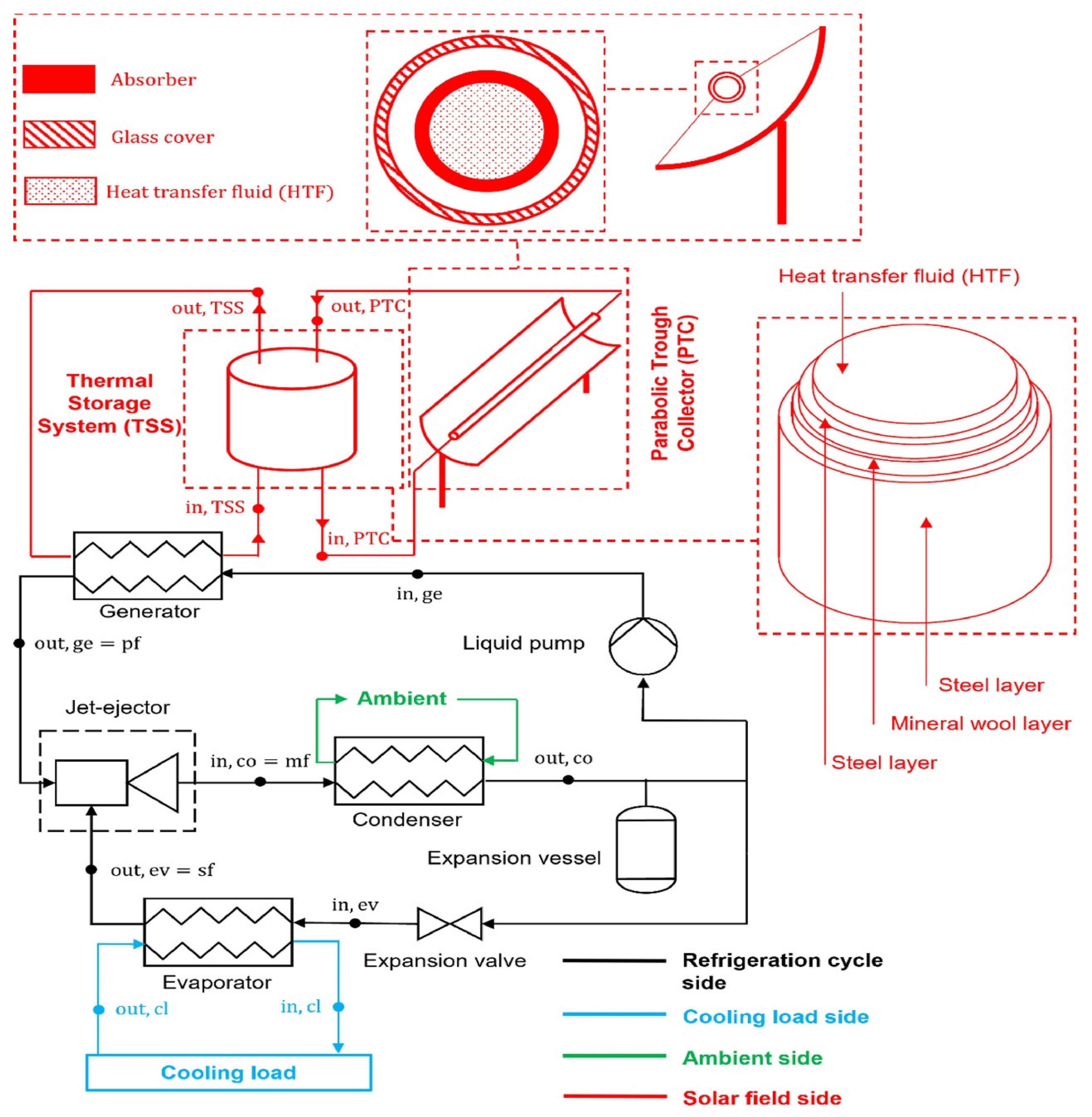
-Luján et al. [136] Q ˙ g e n = m ˙ p f h o u t , g e n t i n , g e n Nominal thermal power extracted from the thermal storage systemOptimization of the thermal storage system in a solar-driven refrigeration system equipped with an adjustable jet-ejector
-Bellos et al. [137] Q ˙ g e n = m ˙ h C p t h , i n t h , o u t Energy in the generator Energetic, Exergetic, Economic, and Environmental (4E) analysis of a solar-assisted refrigeration system for various operating scenarios
-Bellos et al. [101] Q ˙ g e n = m ˙ h C p t h , i n t h , o u t The generator heat inputYearly investigation of a solar-driven absorption refrigeration system with ammonia-water absorption pair
-Mousavi et al. [26] Q ˙ g e n = N P S C · A a p . F R · S Energy in the generatorDevelopment and life cycle assessment of a novel solar-based cogeneration configuration comprised of diffusion-absorption refrigeration and organic Rankine cycle in remote areas
Energy Source: Exhaust Gases or Heat
Origin AuthorsUser AuthorsEquationsEntityApplication
-Aly et al. [99], Adjibade et al. [3] Manzela et al. [119] Q ˙ g e n = m ˙ e x h h e x h , i n h e x h , o u t Q ˙ i n s Energy in the generator
-
Experimental analysis of diffusion absorption refrigerator driven by an electrical heater and engine exhaust gas [3];
-
Using engine exhaust gas as an energy source for an absorption refrigeration system [119]
-
Thermal performance of a diffusion absorption refrigeration system driven by waste heat from diesel engine exhaust gases [99]
-Yildiz [102] Q ˙ g e n = W ˙ e l e c t η e l e c t
Q ˙ g e n = m F H u η c b F t
Energy in the generator Thermoeconomic analysis of diffusion absorption refrigeration systems
-Du et al. [138] Q e x = ρ e x V e x C p e x T e x , i n T e x , o u t
C O P = Q e Q e x
The exhaust heat exchange (generator)Development and experimental study of an ammonia water absorption refrigeration prototype driven by diesel engine exhaust heat
-Chen et al. [56] Q ˙ g e n = Q ˙ c W · C O P C R S m e x h Energy in the generatorAnalysis of an absorption/absorption–compression refrigeration system for heat sources with large temperature change
Energy Source: Geothermal
Origin AuthorsUser AuthorsEquationsEntityApplication
-Salhi et al. [104] Q ˙ g e n = m ˙ f × C p f T w T g Δ T p n Energy in the generator Thermodynamic and thermo-economic analysis of compression–absorption cascade refrigeration system using low-GWP HFO refrigerant powered by geothermal energy
-Tetemke et al. [131] Q ˙ g e n = T H T a t m / 1 h i A i + l n r 0 / r i 2 π k L C + 1 h 0 A 0 Energy in the generator Analyzed vapor absorption refrigeration systems powered by geothermal energy
-Yilmaz and Kaska [132] Q ˙ g e n = m ˙ g e o h g e o , i n h g e o , o u t Energy in the generatorPerformance analysis and optimization of a hydrogen liquefaction system assisted by geothermal absorption pre-cooling cycle
Energy Source: Electrical
Origin AuthorsUser AuthorsEquationsEntityApplication
-Asensio-Delgado et al. [22], Karamangil et al. [4], Lu et al. [139] Q ˙ g e n + m ˙ r f h h x , d = m ˙ r h d , c + m ˙ r f 1 h d , h x
C O P t h = Q ˙ e v a p Q ˙ g e n
Energy in the generatorAnalysis of hybrid compression absorption refrigeration using low-GWP HFC or HFO/ionic liquid working pairs [22].
-
A simulation study of performance evaluation of a single-stage absorption refrigeration system using conventional working fluids and alternatives [4].
-
A techno-economic case study using heat-driven absorption refrigeration technology in UK industry [139]
-Yıldız and Ersöz [33] m ˙ 1 a h 1 a + Q ˙ g e n = m ˙ 3 h 3 + m ˙ 2 c h 2 c Energy in the generatorEnergy and exergy analyses of the diffusion absorption refrigeration system
Energy Source: Ocean Thermal Energy
Origin AuthorsUser AuthorsEquationsEntityApplication
-Hu et al. [140] Q ˙ g e n = 1 η h l Q ˙ S W S Energy in the generatorCompression-assisted absorption refrigeration using ocean thermal energy
Energy Sources: Hybrid Biomass-Solar-Wind Energies
Origin AuthorsUser AuthorsEquationsEntityApplication
-Gado et al. [141] M h o t · C p h o t d T t t d t = Q t h t U A t T t t T a t Thermal storage tankEnergy management of standalone cascaded adsorption-compression refrigeration system using hybrid biomass-solar-wind energies
Table 3. Summary of studies in the literature.
AuthorsFluids/SolutionSource of Energy Usedt° Heat Sourcet° Generationt° EvaporationCooling CapacityCOP
Jianbo et al. [121]LiBr-H2O--- -
Manzela et al. [119]-Engine exhaust gases--4–13 °C14.9–18.4 W-
Nikbakhti et al. [118]LiBr-H2OSolar energy60 °C--13.7 kW0.4
Aly et al. [99]NH3-H2OEngine exhaust gases210 and 220 °C 10 at 14.5 °C15.6–19.5 W0.10
Novella et al. [98]NH3-H2OEngine exhaust gases-165 °C.−10° C--
Kaewpradub et al. [120]LiBr-H2OEngine exhaust gases-105 °C 700 W0.275
Yuan et al. [122]NH3-H2OExhaust gases from marine engines250 °C at 350 °C125 °C at 145 °CAbout −21 °C6.1 kW at 9.9 kW0.16
Ziapour et Tavakoli [100]NH3-H2O-HeThermosiphon90 °C90 °C5 °C5–7 W0.18–0.20
Wang [10]LiNO3-NH3-HeSolar energy92.787.0 °K−13.0 °C1.9 kW0.156
Soliman et al. [123]H2O-LiBrEngine exhaust gases—Phase change materials (PCM) ---0.767 and 0.778
Salhi et al. [104]LiBr-H2O and LiCl-H2OGeothermal energy60–94 °C---0.432 and 0.659
Al-Hamed et Dincer [95]NH3-H2OSolar and geothermal energy 98.7 °C--1.164
Li et al. [97]LiBr-H2OSolar energy—PCM—Heat pump65 °C65 °C-9 kW-
Fitó et al. [60]NH3/LiNO3 and NH3/BaCl2Solar energy80 °C80 °C−10 °C-0.58
Ezzine et al. [12]R124-DMAC mixtureSolar energy90–180 °C 1 kW0.267–0.54
Canan Cimsit et al. [52]LiBr/H2O-R134a-378 K358 K263 K-0.33
Bellos et al. [101]NH3/waterSolar energy160 °C-−20 °C-0.255
Elsayed et al. [146]NH2/H2O/H2 190.5 °C −5 °C8.531 W0.235
Disclaimer/Publisher’s Note: The statements, opinions and data contained in all publications are solely those of the individual author(s) and contributor(s) and not of MDPI and/or the editor(s). MDPI and/or the editor(s) disclaim responsibility for any injury to people or property resulting from any ideas, methods, instructions or products referred to in the content.

