1. Introduction
In the three-phase power transformer, the electromagnetic forces acting on cleats and leads (C&L) conductors can be enormous. Especially in the case of an operational short circuit of power transformers with tertiary winding with a reduced power, the current density in C&L may reach the value of 280 A/mm
2, which gives a peak phase current of approximately 100 kA, as in the case of the power transformer shown in
Figure 1. The damage of the insulation of the cables in this transformer after the short circuit test is shown in
Figure 1. This figure depicts three cables from three different phases near the core press plate. The insulation of those cables was destroyed near the supporting ribs due to the oscillation of cables during the short circuit test. This kind of failure is very difficult to predict during the design phase of a power transformer. To prevent the failure of insulation, the electromagnetic forces acting on the cables must first be known. Because cables are close to the core press plate, which is made of ferromagnetic material, forces acting on the cables cannot be determined by using an analytical formula. These forces can be determined by using magnetic stimulation. After knowing the force acting on cables, dynamic mechanical simulation must be conducted to simulate the oscillation of cables, and some failure criteria for insulation must be proposed. Building such a complex multiphysics model is time-consuming and much knowledge is needed. As each power transformer is designed individually according to customer needs, the cleats and leads designer does not have enough time to perform such a time-consuming algorithm. The idea of this publication was to develop analytical formulas that will approximate forces acting on conductors in the steady state of AC current. Having such analytical formulas helps the designer to calculate forces very quickly without using magnetic numerical simulation. This paper will not discuss the mechanical part of the problem. The mechanical model of the cable is awaited in further research.
There is a very limited number of publications about forces acting on C&L conductors. However, there is a great number of papers focusing on short-circuit forces acting on the windings, and some of them will be described here. To determine short-circuit forces in windings, three main methods were used: numerical simulation, analytical formulas, and experiments. In ref. [
1], a finite element method (FEM) simulation was used to calculate the electromagnetic field in the core and windings and determine forces during short-circuit and inrush conditions. The authors prepared two-dimensional and three-dimensional models of windings and compared axial and radial forces obtained from both simulations. The main conclusion was that there was a significant difference between forces calculated by 3D and 2D simulations. The radial force in the case of the 2D simulation was underestimated. In ref. [
2], a magnetostatic analysis of the winding conductor was used to calculate the peak value of the force acting on windings. The peak forces calculated by the magnetostatic analysis were transferred to a static mechanical simulation to calculate the maximum deformation of the winding and determine its mechanical stiffness. Based on this coupled simulation, the critical buckling load for transformer winding was determined. The authors also prepared an experimental stand and measured the force in the short-circuit state and confirmed that the critical buckling load from the simulation differs by only 2.3% from the critical value obtained from the experiment. This publication shows how effective a good FEM method for the multiphysics system can be. Publication [
3] presents a full dynamic multiphysics model of windings. The authors used a 2D transient simulation to calculate the dynamic electromagnetic forces acting on windings during the short circuit. The authors developed a mechanical model of windings and applied calculated forces from electromagnetic simulation to those windings. Based on a transient mechanical simulation, the deformation in winding and stresses in conductors as a function of time was determined. A similar approach of a multiphysics dynamic simulation was used in ref. [
4] and ref. [
5]; however, here, both the electromagnetic simulation and mechanical simulation were made using 3D transient solvers in COMSOL software.
Based on the presented publications, it can be concluded that using a multiphysics model to calculate forces acting on winding conductors and the mechanical response is widely used. However, building such a model is time-consuming. Therefore, an analytical approach to calculating forces is needed. Analytical formulas for radial and axial short-circuit forces were developed in ref. [
6] and compared to results from numerical simulations. The results of the numerical simulation are in good agreement with the analytical formulas presented by the authors.
This paper concentrates on forces acting on the C&L of the power transformer. The authors found some selected publications discussing the geometry of straight conductors, which are similar to the problem in this paper. In ref. [
7], a geometry consisting of three parallel busbars was analyzed. The forces acting on the busbars were calculated using the analytical formula. A mechanical transient simulation was conducted to determine the deformation and mechanical stresses in the busbar. It should be mentioned that the use of analytical formulas to determine the forces was possible because the geometry was simple and there was no ferromagnetic material near the conductor, which is not the case with the system described in
Figure 1. In ref. [
8], a full multiphysics numerical model concerning electromagnetic, thermal, and mechanical phenomena was discussed. Based on this model, the dynamic deformation and equivalent stresses in busbars caused by electromagnetic forces and thermal effects were determined.
Comparing ref. [
9], which presents the classical approach to modeling of short circuit state of power transformers to the more up-to-date refs. [
10,
11], it can be concluded that the requirements for modeling of the short circuit state operation of power transformers have significantly increased and currently numerical simulations are used more frequently to better model physics of short circuit state.
The discussed problem of the failure of the insulation is very complex because it involves both electromagnetic and mechanical phenomena. In order to fully solve the discussed problem, a multiphysics simulation is needed, consisting of an electromagnetic simulation and mechanical simulation. This paper focuses only on determining forces acting on the conductors of the cleats and leads of a power transformer. The mechanical modeling of a cleats and leads conductor is in progress and will be discussed in the next paper. As the conductor of cleats and leads consists of hundreds of small copper wires wounded helically and insulation wrapped around the copper part, the mechanical modeling of such a system by the use of a numerical simulation is very difficult. Due to the complex geometry of the cables, the system is highly nonlinear, and force cannot be applied by one step, but by gradually increasing the force, which makes a mechanical simulation very difficult and time-consuming. Moreover, in this publication, the authors did not concentrate on the modeling of one case of a power transformer or a few cases, but rather developed a general approach on how to determine forces acting on cleats and leads conductors, analyzing the results from thousands of design points from parametric simulations and analytical formulas.
In
Section 2, the analytical formula for forces acting on the cleats and leads conductors in a standard three-phase system without a ferromagnetic plate is determined. In
Section 3, the authors describe the methods and results of the parametric numerical simulation of a magnetic field, concentrating on calculating forces acting on mentioned conductors. Firstly, the case without a ferromagnetic plate is discussed, and the results of the simulation are compared to the analytical equation from
Section 2. As the next step, a number of parametric simulations with geometry consisting of three cables and a magnetic plate are presented. The forces determined by the numerical simulation were compared to the standard analytical formula from
Section 2. In
Section 3, the influence of geometrical parameters, as well as eddy currents in plate and cables, on forces acting on conductors is discussed. Based on parametric numerical simulations, the authors checked which parameters have a significant influence on the forces acting on the conductors and developed new improved formulas for forces acting on conductors near a ferromagnetic conductive plate, which are discussed in
Section 4. In
Section 5, all conclusions from the whole publication are presented.
3. Numerical Simulations
The main goal of this publication was to study the forces acting on a three-phase system of cables situated close to the active part of the power transformer and carrying sinusoidal currents. This system is usually located near the ferromagnetic plate pressing the core as is shown in
Figure 1. The said plate is made of a conductive, ferromagnetic material and, as will be described later, its presence has a great influence on the forces acting on the cables. Therefore, the analytical Equation (4) cannot be used directly. In order to calculate forces acting on the conductors, a numerical simulation must be applied.
The numerical simulation was conducted in ANSYS Maxwell 2021 R1 software in the eddy current module. This solver assumes that all quantities, such as the current density and magnetic field density, are sinusoidal changing with a defined frequency, so it only calculates the steady state of the
AC current. The mentioned solver numerically solves the Maxwell equations in the form presented below [
12].
As a next step, the instantaneous force acting on each conductor was calculated by integrating Equation (9) over the volume of the cable [
12].
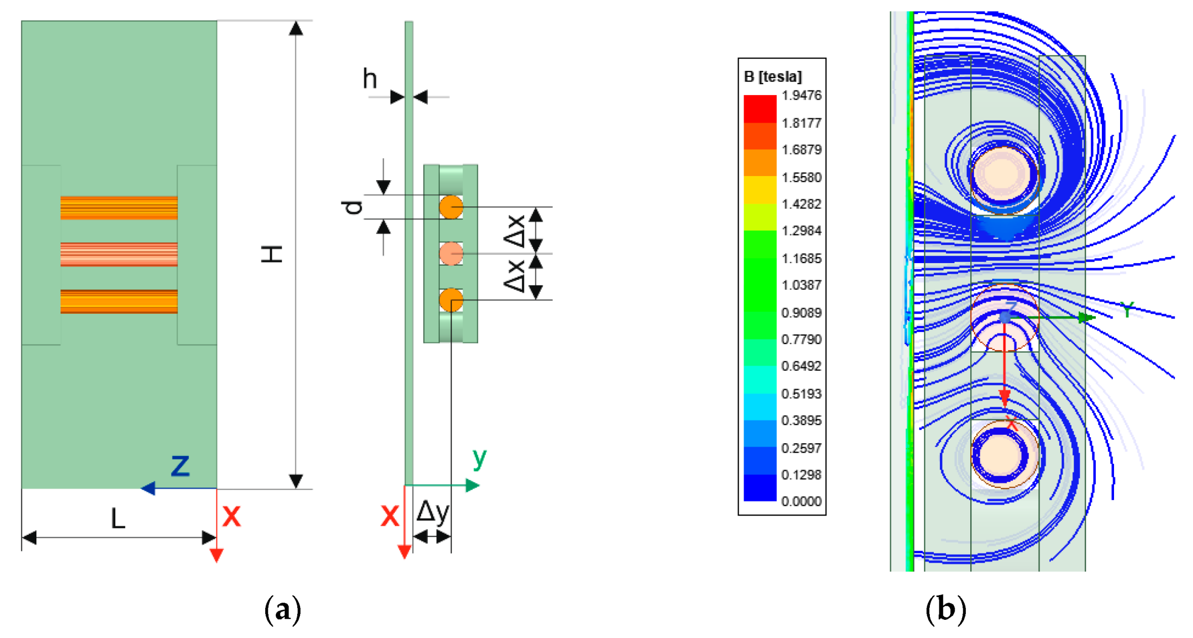
Firstly, a parametric model consisting of three parallel cables supported by wooden brackets near the ferromagnetic plate was created. (
Figure 3a) The presented parametric geometry is very close to the real geometry shown in
Figure 1. By modifying the parameters (
d, Δ
x, Δ
y,
L,
H,
h), the geometry of the model can be changed and the influence of geometrical parameters on the force acting on the conductors can be investigated. The boundary condition assigned to all external surfaces of the model is a magnetic field tangent. As the excitation, the total current flowing through the cross-section of the cable was assigned to be the AC with amplitude I.
In the first simulation, the plate was omitted and eddy currents in cables were neglected. The instantaneous forces acting on cables obtained from the simulation are shown in
Figure 2b. The force acting on the upper and bottom conductor consists of an
AC component of
frequency and a
DC component, whereas, for the middle conductor, only the
AC component is present. This is exactly as discussed in
Section 2. Moreover, the numerical values of the
DC force and
AC force amplitude from theoretical Equation (4) are the same as those calculated by Maxwell software. This consistency in results between the simulation and theoretical formulas confirms that the simulation model is correct.
In order to investigate the influence of the plate on forces, a simulation with a plate made of ferromagnetic material with constant relative permeability µ
r = 290 was conducted. Linear B-H characteristics were used to improve the speed of the simulation. The selected value of relative permeability was chosen according to the authors’ experience. The results of selected linear simulations were compared to the simulation with nonlinear characteristics, and the difference between those results was considerably low. Four different simulations were carried out for the same geometry to investigate the influence of eddy currents in the plate and conductors on forces acting on the cables. In the first simulation, the plate was assumed to be nonconductive, and the conductors were stranded (eddy currents were neglected). The forces acting on the cable in the
x-direction are shown in
Figure 4a. Comparing forces acting on cables near a non-conductive plate (
Figure 4a) to forces acting on the conductor when the plate is not present (
Figure 2b), it can be observed that the amplitude of forces is 25% higher when the plate is present. The force acting on the cables close to the nonconductive plate in the y-direction is shown in
Figure 4b. In the case of simulation without the plate, the force in the y-direction is zero. From those simulations, two main conclusions can be drawn. Firstly, adding a ferromagnetic plate increases the magnitude of the force in the x-direction. Secondly, when the plate is present, a new component of force in the y-direction is present. This finally confirms that using the standard analytical Equation (4) is not enough because it will underestimate the forces.
In the second simulation, the eddy currents in plates were added, but eddy currents in cables were neglected. The assumed conductivity of the plate was 6.7 × 10
6 S/m. The graphs of instantaneous forces are very similar to those shown in
Figure 4, so they will be omitted. After adding eddy currents to the plate, the force in the
x-direction is lower than when eddy currents were not included in the model. Moreover, the induced eddy currents in the plate caused a nonzero DC force acting on the middle conductor, which was not the case for simulations without eddy currents.
In the third simulation, only eddy currents in the cable were activated and the plate was non-conductive. In this case, the DC force for the middle conductor was again nonzero. This clearly shows that adding the eddy currents either in cables or in the plate causes the DC force in the middle conductor and that the system is unsymmetric (the amplitudes of forces acting on the upper and lower conductor are also not the same). Moreover, the AC component of force is bigger if eddy currents are present in cables. In the last simulation, both currents in the cable and plate were taken into consideration, and the superposition of effects discussed earlier was present in this case.
In order to investigate the influence of geometrical parameters such as the distance between cables Δ
x or distance between cables and plate Δ
y on forces, a parametric simulation for each of the previously mentioned simulations was conducted. In order to better analyze the results, the forces acting on cables without a plate calculated by analytical Formula (4) were treated as the reference and the correction factors were defined to better visualize the influence of the ferromagnetic plate and eddy currents in cables and in the plate. The correction factors for the
AC and
DC force for the bottom and upper conductor and AC force for the middle conductor, given in Equations (10) and (11), can be used. The mentioned correction factors define the ratio of the force when the plate is present to the force obtained from the analytical formula. The same concept of the correction factor cannot be used for the
DC force of the middle conductor, so the correction factor for the
DC force for the middle conductor is defined, according to (12), as the ratio of the
DC force with a plate to the
AC force according to the analytical formula. As the forces in the y direction are significantly lower than in the
x direction, they are not discussed in such detail.
Now, the results of the mentioned parametric simulation will be discussed using corrections factors. Analyzing
Figure 5a,b, it can be concluded that adding a plate always increases the force acting on the bottom conductor. The increase in force is bigger when the cables are very close to the ferromagnetic plate. Secondly, adding the eddy currents in plates always decrease the force in the bottom cable. However, adding the eddy current in the cables increases the force in the bottom cable. As can be seen, the increase in the force may reach 60% for the
AC component and 40% for the
DC component. This clearly shows that the influence of ferromagnetic plates and eddy currents in cables should not be neglected during the design process.
Analyzing
Figure 5c,d, it can be concluded that the forces acting on the upper conductor are lower than the forces acting on the bottom conductor (
Figure 5a,b) if eddy currents are included either in cables or in the plate. This means that the eddy currents make the system unsymmetric. Similarly, as for the lower conductor, the eddy currents in the plate decrease forces acting on the upper conductor, and eddy currents in cables increase the forces acting on the upper conductor. This asymmetry depends on different phases of currents in bottom and upper conductors, and not on the geometry of the system.
The same conclusions can be drawn for the
AC force acting on the middle conductor based on
Figure 6a. Eddy currents in the plate decrease the
AC force acting on the middle conductor, and eddy currents in conductors increase this force.
Figure 6b–d show the correction factor for the DC force acting on the middle conductor for different distances between cables (35, 50, and 100 mm, respectively). In the case where eddy currents are neglected both in the plate and conductors, the DC component is zero. After adding conductivity to the plate, this force is nonzero due to eddy currents in the plate. Similarly, in the case of a solid conductor near a non-conductive plate, the force is also nonzero due to eddy currents in cables. However, the direction of force caused by eddy currents in a conductor is opposite to the direction of force caused by eddy currents in the ferromagnetic plate. This cannot be seen in the graphs below because those graphs only analyze absolute values of forces. Finally, after adding the eddy currents in both the conductor and plate, the superposition of both forces exists. As the directions of the forces are opposite, the values of the forces are subtracted. The component of the force coming from eddy currents in the conductor mainly depends on the distance between conductors and the diameter of the conductor. The closer the conductors are to each other, the more important this force is. On the other side, the force caused by eddy currents in the ferromagnetic plate is strongly dependent on the distance between cables and the plate. The closer the cables are to the plate, the higher this force is. As a result, depending on the geometry, either the force caused by eddy currents in cables or the force caused by eddy currents in plates is higher, which can be seen in
Figure 6b–d.
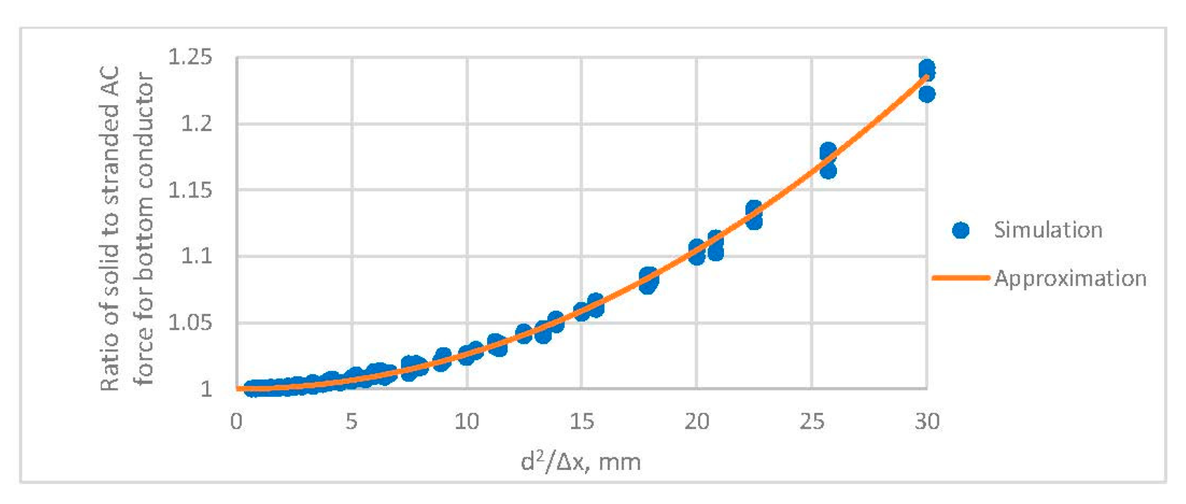
In the previous simulation, the diameter of the cable was assumed to be 30 mm. However, eddy currents in cables strongly depend on the diameter of the cable and the distance between the conductors. For this reason, a parametric simulation with the diameter of the cable changing from 10 to 30 mm and the distance between cables changing from 35 mm to 300 mm was performed.
Figure 7a presents the ratio of the
AC force acting on the bottom solid conductor to the
AC force acting on the stranded one for different values of the diameter of the cable and the distance between cables. This figure clearly shows that the influence of eddy currents is more significant for a large diameter of the cable and when cables are close to each other. This can be explained by the proximity effect. Due to the proximity effect, the magnetic field produced by one cable influences the current distribution in the second cable. The smaller the distance between the cables, the bigger the influence of the magnetic field induced by one conductor in the other one. The bigger the diameter of the cable, the smaller the resistance of the cable, and eddy currents in the cable have higher values. In
Figure 7b, the current density in the cable and the ferromagnetic plate is shown for phase angle 0. It can be seen that the current distribution is not uniform because one magnetic field of a neighboring conductor influences the current distribution in another one.
The mentioned ratio of solid to stranded
AC force for the bottom conductor can be approximated by Equation (13). A similar analysis was conducted for the other components of the force and the approximation functions will be described in the next section.


