Article

Exergy Load Distribution Analysis Applied to the Dehydration of Ethanol by Extractive Distillation

by
Camilo Andrés Guerrero-Martin
1,2,3,*,
Juan Sebastián Fernández-Ramírez
4,
Jaime Eduardo Arturo-Calvache
5,*,
Harvey Andrés Milquez-Sanabria
5,
Fernando Antonio da Silva Fernandes
2,
Vando José Costa Gomes
1,2,3,
Wanessa Lima e Silva
1,2,3,
Emanuele Dutra Valente Duarte
1,2,3,
Laura Estefanía Guerrero-Martin
1 and
Elizabete Fernandes Lucas
6,7,*
1
LOTEP—Laboratório de Operações e Tecnologias Energéticas Aplicadas na Indústria do Petróleo, Faculty of Petroleum Engineering, Federal University of Pará, Salinópolis 66075-110, Brazil
2
Department of Engineering, Federal University of Pará—Campus Salinópolis, Rua Raimundo Santana Cruz, 9 S/N, Bairro São Tomé, Salinópolis 68721-000, Brazil
3
LEEPER—Laboratório de Ensino de Engenharia de Poco e Reservatório, Faculty of Petroleum Engineering, Federal University of Pará, Salinópolis 68721-000, Brazil
4
Departamento de Ingeniería Química y Ambiental, Universidad Nacional de Colombia, Bogotá 111321, Colombia
5
Departamento de Ingeniería Química y Ambiental, Fundación Universidad de América, Bogotá 111221, Colombia
6
Metallurgical and Materials Engineering Program/COPPE/LADPOL, Federal University of Rio de Janeiro, Av. Horácio Macedo, 2030, Bloco F, Rio de Janeiro 21941-598, Brazil
7
Institute of Macromolecules/LMCP, Federal University of Rio de Janeiro, Rua Moniz Aragão, 360, Bloco 8G/CT2, Rio de Janeiro 21941-594, Brazil
*
Authors to whom correspondence should be addressed.
Energies 2023, 16(8), 3502; https://doi.org/10.3390/en16083502
Submission received: 17 January 2023 / Revised: 25 February 2023 / Accepted: 30 March 2023 / Published: 18 April 2023

Abstract

:
This study presents the analysis of the exergy load distribution in a separation process by extractive distillation for ethanol dehydration. The methodology carried out is divided into three parts: the calculation of the flow exergy considering the physical and chemical exergies of the distillation process; the calculation of the primary and transformed exergy contributions considering the consumed exergy; and finally, the overall process efficiency, which shows the real percentage of energy being used in the process. The simulation of an extractive distillation separation system is carried out using Aspen Plus®, from Aspen Tech Version 9. In general, heat transfer processes (heating or cooling) are the ones that generate the greatest exegetic destruction, which is why they must be the operations that must be optimized. As a result of our case study, the local exergy efficiency of the extractive distillation column is 13.80%, which is the operation with the greatest energy loss, and the overall exergy efficiency of the separation system is 30.67%. Then, in order to increase exergy efficiency, a sensitivity analysis is performed with the variation of the azeotrope feed, number of stages, reflux ratio, and solvent feed variation on ethanol purity to reach an overall efficiency of 33.53%. The purity of ethanol is classified as higher than that of the specified, 99.65%.

1. Introduction

Currently, there is a variety of raw materials for obtaining biofuels. Many studies use a series of products or by-products, such as tires [1], plastic waste [2], algae [3], wood [4], leaves or branches [5], due to the economic potential of biomass. Biofuel production is classified into four generations based on feedstock and production methods [6].
With the significant increase in biofuels, according to the International Energy Agency (IEA), the world demand for biofuels will grow by 28% during the period 2021–2026, which is equivalent to 41,000 million liters [7]. Worldwide, demand for bioethanol doubles that of biodiesel. By 2021, according to IEA data, the demand for this biofuel was 102 billion liters/year, while that of biodiesel was 44.5 billion liters/year [8]. Therefore, the productive sector of bioethanol is looking to develop separation technologies that allow the attainment of high efficiencies related to ethanol recovery and energy consumption [9].
One of the most commonly used technologies to separate ethanol is extractive distillation, due to its technical and economical practicality [10,11,12,13]. However, the concept of the efficiency of the acquisition of alcohol depends on the amount of energy consumed in the process. This develops a concept that allows relating the efficiencies of each operation present in the system with global efficiency [14]. This concept is called exergy load distribution, and it is defined as an integration of local efficiencies of energy quality and the waste of energy involved in a process [15,16,17].
When talking about exergy, the theoretical maximum work that can be obtained when a stream of matter or energy in a system in specific conditions reaches thermodynamic equilibrium with environmental conditions is discussed [18]. Therefore, there is energy involved in this equilibrium that could be usable but that cannot be used due to its quality [19]. This concept of energy quality is given by the destruction of exergy, which is explained as the thermodynamic irreversibility that a certain process or operation has when defined by specific conditions [20,21].
The application of exergy load distribution analysis in product design is reported in different research, including on water distribution systems [22], hybrid renewable energy systems in buildings [23], flue gas condensation waste heat recovery systems [24], biodiesel transesterification [25], bioethanol [26], biobutanol [27], methane [28], and hydrogen [29]. In the same way, process design can be analyzed by exergy load distribution: pyrolysis [30], combustion [31], gasification [32], and torrefaction processes [33]. This process analysis model allows for not only taking into account the technical aspects of the design but also taking into account environmental aspects, which are fundamental to sustainable development.
The thermochemical conversion processes used to transform biomass into fuels and chemicals are direct combustion, liquefaction, pyrolysis, fermentation, etc. [34]. The production of ethanol by the fermentation of sugar cane gained great importance in the Brazilian energy sector 15 years ago, having thus developed and improved its technology and industrial aspects. However, even with many studies about the type of raw material used in the manufacture of biofuels. Still, there are few studies on the design of the distillation column, which thus expends a lot of energy in the distillation process. In this way, we are presenting a sector that needs to improve in order to increase the efficiency of the energy generation process.
García-García et al. (2018) [35] propose an exergy analysis aimed at reducing energy consumption in an extractive distillation column. In this study, a conventional exergy analysis is observed, and a sensitivity analysis is performed, resulting in a decrease in the operating energy and an increase in the exergy efficiency of the column. These results show the relevance of integrating exergy into the processes; a simple analysis can greatly impact energy savings.
This work presents a study equivalent to the one developed by García-García et al. (2018) [35] for the extractive distillation process in ethanol dehydration, but using the exergy load method, which although not new, has few references available for this specific case study in the extractive distillation process. The exergy load method focuses on the analysis of the exergy losses that occur during the heat and mass transfer process in the distillation column, which allows a more detailed evaluation of the exergy efficiency. Using a sensitivity analysis, through the evaluation of the efficiencies of the constituent elements of the process as a complement to the usual exergy method, the distribution of loads between the elements is identified, resulting in an increase in process efficiency.
The Aspen Plus® process simulator is used to obtain the main thermodynamic parameters used for the evaluation and determination of the exergy in the process, as well as a parameter sensitivity analysis. As a result, the local exergy efficiency of the extractive distillation column is 13.80%, which is the operation with the greatest energy loss, and the overall exergy efficiency of the separation system is 32.38%. Then a sensitivity analysis was performed, and the results obtained describe that if the azeotrope feeding of the mixture is from the tenth stage, a higher overall efficiency is observed. Added to this, the purity of ethanol is classified as higher than that specified, being 33.53% and 99.65%, respectively, for a case that describes feeding on the eleventh stage and with sixteen steps in the column.

2. Materials and Methods

The first step for the exergetic analysis by load distribution is to calculate the physical and chemical exergies of the extractive distillation process streams, as follows:

2.1. Exergy Analysis

The exergy of flow, E ˙ i s , is defined as the sum of exergies involved in the process stream, i. However, the kinetic and potential exergy is negligible [36]. Therefore, the exergy of the flow is defined by the physical exergy, E ˙ f i , and chemical, E ˙ x i , which are known by Equation (1).
E ˙ i s = E ˙ f i + E ˙ x i
Physical exergy contributes to the flow exergy through changes in the pressure and temperature of the process stream; thus, Equation (2) defines the physical exergy.
E ˙ f i = m ˙ i ( ( h i h 0 ) T 0 ( s i s 0 ) )
where m ˙ i is the flow of matter entering the system, h i is the specific enthalpy of the mix in each state, h 0 is the specific enthalpy of the mix in reference state, s i and s 0 correspond to the entropy of the mix in a determined in each state and in reference state. Furthermore, T 0 , corresponds to the temperature of the reference state.
In chemical exergy, only the composition of each compound present in the mixture is considered, as well as chemical transformations that occur in the process [37]. It is defined by Equation (3).
E ˙ x i = i n k ( e x , i + R T 0 ln | x k | )
where the term n k is the molar flow of component k , x k is the molar fraction of component k in the mix; e x , i is the chemical molar exergy of the pure component k ; and R corresponds to the ideal gas constant.
In the evaluation of the destroyed exergy of the system, Equation (4) is applied, which shows the exergy of the specific flow, e i s ; the relation of heat losses, Q ˙ j ; and the consumption of the generation of work in a determined equipment, W ˙ j . The determination of destroyed exergy is performed for an operation j, and it is from these losses that the method to be studied is centered.
E ˙ d j = j ( 1 T o T j ) Q ˙ j W ˙ j +   i n m ˙ e i s   o u t m ˙ e i s
Once the above-mentioned exergies have been determined, the next step is to perform the load distribution analysis.

2.2. Analysis by Exergy Load Distribution

According to Sorin and Brodyansky [14], exergetic efficiency is defined as:
η e = A B = B D B = 1 D B
where A is the total product exergy of a system, B is the total exergy consumed in a system, and D is the total exergy losses in a system. The difference between the denominator and the numerator of Equation (5) must be equal to the total exergy losses, therefore:
D i = B i A i
D = D i
Substituting Equations (6) and (7) into Equation (5) and solving:
η e = 1 B i B   A i B i B i B = λ i η e , i + 1 λ i
where B i is the exergy consumed by each element of a system, λ i = B i B and η e , i =   A i B i
Considering the equations mentioned above, the exergy consumed by each element is divided into two groups: (I) the exergy consumed in every local operation makes up a part of the exergy consumed in the whole system, called primary exergy, λ p , i (Equation (9)) and (II) the exergy consumed by one element does not make up for a part of the exergy consumed in the whole system, called transformed exergy, λ t , i (Equation (15)).
In other words, the load of primary exergy refers to the difference between the flow of exergy, which passes through each local operation, and the total of the consumed exergy [10,11,38].
λ p , i = Δ E ˙ p , i s i Δ E ˙ p , i s
The primary exergy loads for each of the components of the technological scheme of the extractive distillation considered according to Equation (9) correspond to the following expressions:
λ p ,   H = ( E ˙ A Z E + E ˙ S O L V R E C E ˙ R E C S O L H E ˙ A Z E S A T ) T o t a l   e x e r g y   c o n s u m e d
λ p ,   M I X E R = ( E ˙ E N T R A I N E ˙ M A K E U P E ˙ R E C S O L V H ) T o t a l   e x e r g y   c o n s u m e d
λ p ,   C 1 = ( E ˙ E t O H + E ˙ M I X E ˙ A Z E S A T E ˙ E N T R A I N ) T o t a l   e x e r g y   c o n s u m e d
λ p ,   C 2 = ( E ˙ W A T E R + E ˙ S O L V E ˙ M I X ) T o t a l   e x e r g y   c o n s u m e d
λ p ,   P u m p = ( E ˙ S O L V R E C E ˙ S O L V ) T o t a l   e x e r g y   c o n s u m e d
On the other hand, the load of the transformed exergy will be equal to the difference between the flow exergy that has undergone a change within the local operation and the total of the consumed energy [14,15,16,17]. The load of transformed exergy can be easily identified in the units that increase the exergy in the entrance flow, that is, equipment that increases exergetic conditions (temperature, pressure, or chemical composition) for a posterior operation in the process.
λ t , i = Δ E ˙ t , i s i Δ E ˙ p , i s
The transformed exergy loads for each of the components of the technological scheme of the extractive distillation considered according to Equation (15) correspond to the following expressions:
λ t ,   P u m p = ( E ˙ S O L V R E C E ˙ S O L V ) T o t a l   e x e r g y   c o n s u m e d
λ t ,   M I X E R = ( E ˙ E N T R A I N E ˙ M A K E U P E ˙ R E C S O L V H ) T o t a l   e x e r g y   c o n s u m e d
If we add Equations (9) and (15), we have a portion of the exergy that enters an element or unit:
λ i = λ p , i + λ t , i
Considering that the sum of all primary exergy streams must be equal to one and replacing Equation (18) in Equation (8), we obtain the overall efficiency, which is defined as:
η = i [ λ p , i η i λ t , i ( 1 η i ) ]
This equation demonstrates the relationship between the exergetic efficiency of each local operation and the overall efficiency of the system. It can be said that the global efficiency can be improved by increasing the local efficiency, as long as it does not affect other parameters of the equation, or by decreasing the loads of primary or transformed exergy [14,15,16,17].

3. Results and Discussion

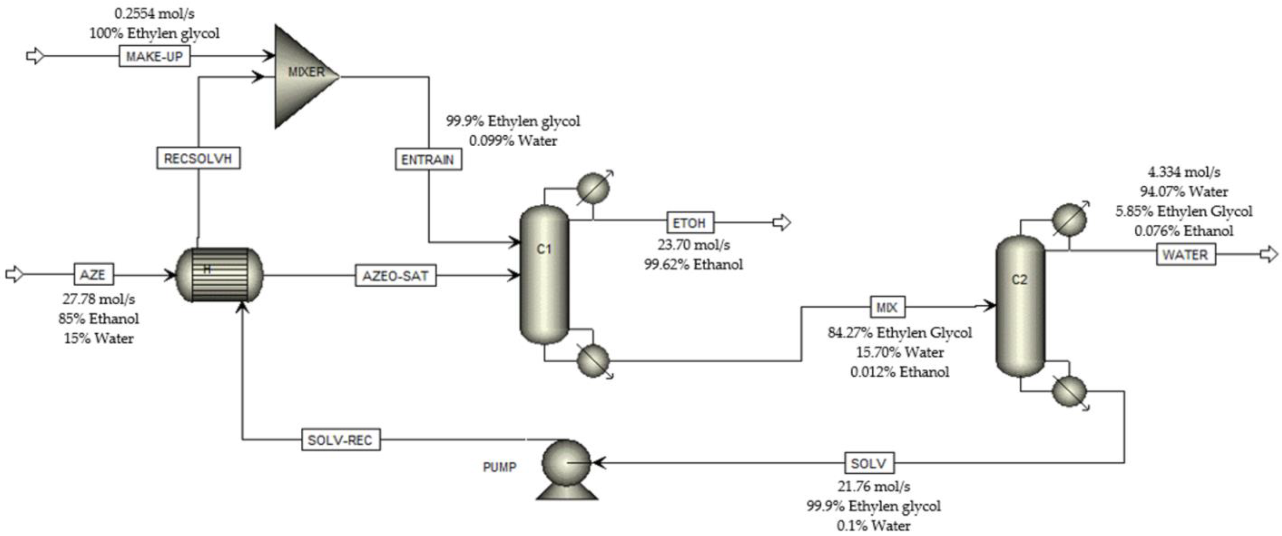
3.1. Extractive Distillation Process Simulation

The work of Uyazan et al. (2006) [38] is the starting point for the exergy study of the technological scheme of extractive distillation, but with a different solvent. In the build of the plant design to obtain anhydrous ethanol by extractive distillation, two distillation columns were used in series. The first carries out ethanol dehydration, using ethylene glycol as a solvent. The first distillation column is fed with a composition of 85 mol% ethanol, which is fed into the eleventh stage of the column (the AZEO-SAT stream) and ethylene glycol is fed pure to the fourth stage of the column (the ENTRAIN stream). Column C1 is operating at a pressure of 101.325 kPa; no pressure drop is considered in any of the column stages. The AZEO-SAT and ENTRAIN streams are incoming at a temperature of around 351.3 K (once the recycling is completed). The output MIX stream is at a temperature of 426.94 K, and the output ETOH stream is at a temperature of around 351 K. The product obtained at the top of the extractive distillation column is ethanol (the ETOH stream), with a purity of 99.62%, and the product at the bottom is a mixture composed mainly of ethylene glycol and water (84.27% and 15.71%, respectively). The MIX stream is the feed for column C2, which enters in stage four (Figure 1). An operating pressure of 2 kPa was specified for column C2, since these conditions reduce the energetic consumption and avoid high temperatures in the boiler. The SOLV stream (recovered ethylene glycol) goes through a heat exchanger, H, to be mixed with the MAKE-UP stream, which is pure ethylene glycol, thus completing the ethanol production process. The technological scheme was obtained in Aspen Plus®, as shown in Figure 1. The thermodynamic model selected to perform the simulation was the NRTL because it proved to be the best to correlate the experimental data obtained by Meirelles (1992) [39], such as the simulation data of the present study.
Table 1 shows the energy flows in the simulated system. When this system is compared with the study made by Uyazan et al. (2006) [38], it shows that the results are similar in terms of the energy consumed by distillation towers. From these results, an improvement in the efficiency of the column C1 can be made by improving the operating condition through an exergetic analysis of load distribution.

3.2. Determination of Flow Exergy

Table 2 shows the necessary thermodynamic parameters to evaluate the exergy of the process; it also shows the results of the physical, chemical, and flow exergy of the process streams. To know the molar chemical exergy of each component involved in the separation process, we used the standard chemical exergy tables reported by [40,41]. The standard exergy values for each of the chemical compounds in the process can be found in these tables. Values of 1356.9 kJ/mol, 0.9 kJ/mol, and 1214.21 kJ/mol are obtained for ethanol, water, and ethylene glycol, respectively. Once identified, Equation (3) is used to find the chemical exergy of each process stream. These tables have the limitation of only having general chemical compounds. In a case in which the standard exergy is not found, the process to calculate it is more rigorous. This process is better explained in [41].
This table shows that in the AZE stream, composed of ethanol and water, there is no contribution from physical exergy because this stream enters the heat exchanger under standard conditions; therefore, there is no variation in the thermal or mechanical components characteristic of these exergy types, the opposite of what occurs in the AZEO-SAT stream. Note that there is a change in the temperature with respect to the specified standard. However, there is a contribution to the chemical exergy in the AZE stream since there are changes in the exergy chemical balance of the compounds, ethanol, and water, since together they form a mixture to be separated, thus obtaining that the exergy of the flow is the same as the chemical exergy of the stream.
If the temperature of the WATER stream is observed, it is easy to deduce that the operation condenser temperature is lower than the temperature specified as a reference. This has an important impact on the exergy transferred by heat calculation since a negative term is shown in the heat transfer, which means that the exergy of the condensing medium decreases, generating a reduction in the loss of quality in the energy supplied to column C2. This will be better discussed in the next section.

3.3. Destroyed Exergy Determination

Once the flow exergy has been calculated, the destroyed energy balance is made for each operation in the process, as seen in Equation (4); this allows us to identify which equipment has the biggest irreversibility in the process. In Figure 2, it can be observed that the unit with the most exergy destruction is column C1, identified as the extractive distillation column, with a contribution percentage of 75.20% of the total exergy destroyed in the entire separation system (the thickness of the arrows agrees with the numerical value of the magnitude considered). This is mainly due to the large amount of energy required in the distillation unit for the condensation and overheating sequence in the streams that feed the tower, so speaking in terms of performance, column C1 is energetically inefficient [42].
As mentioned before, having a negative heat transfer in C2 from the environment to the condenser causes a decrease in the destroyed exergy, so it will be more efficient in terms of energy. The main cause is the sub-atmospheric condition in which the ethylene glycol recuperation tower works, making it more effective at separating without a considerable loss of useful energy. Table 3 shows the exergy destroyed in each of the operations.

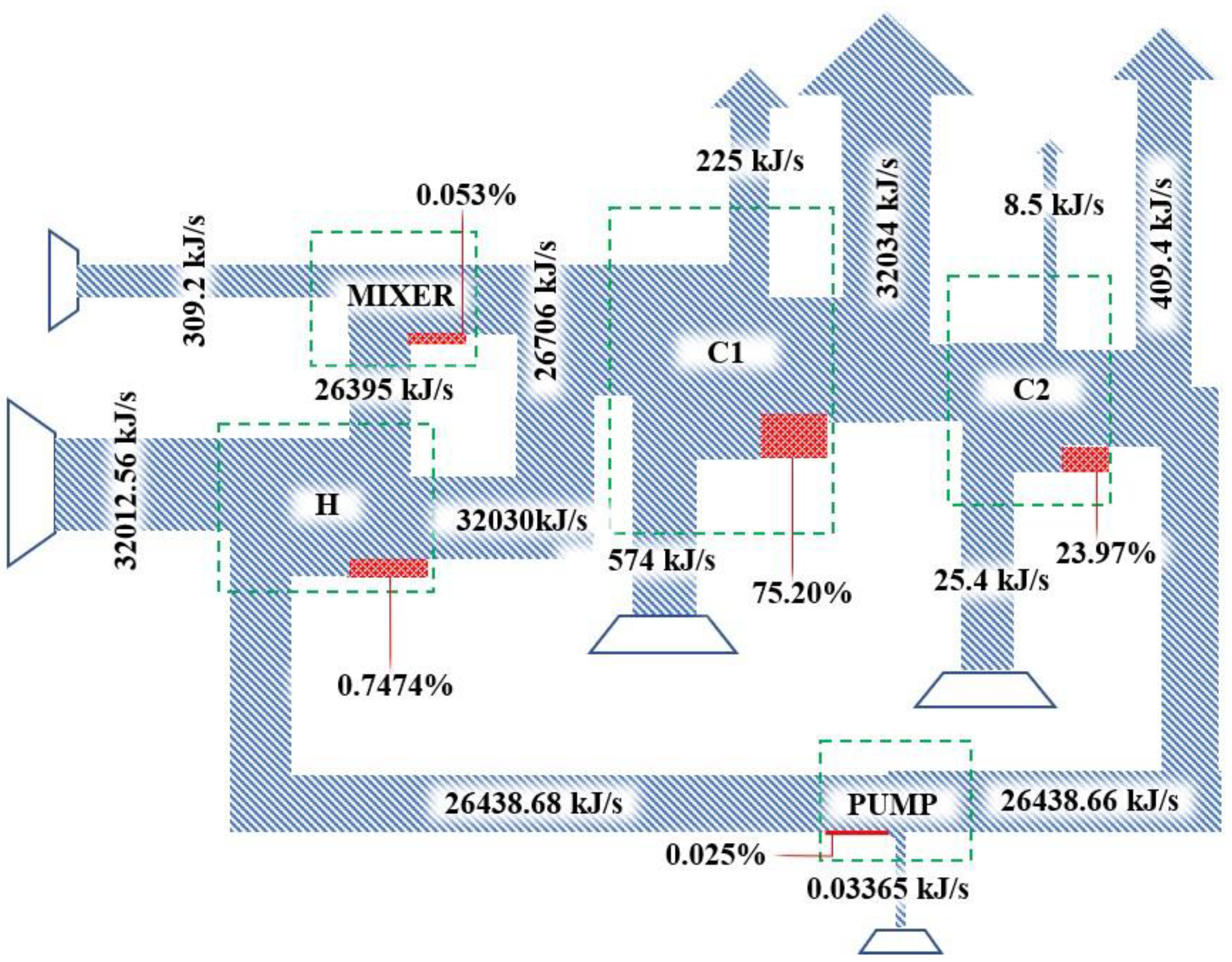
3.4. Application of the Exergy Load Distribution Method

As seen in Equations (9) and (15), primary and transformed exergy are given by total exergy consumption. This total exergy is known as the sum of the local flow exergy balances, that is, the sum of exergy flow differences in each unit of the alcohol dehydration process. Once this is identified, it is possible to know the primary exergy load of the separation system. It is noteworthy that primary exergy has a restriction in the process, and that the sum of primary exergetic loads must be equal to one [14].
To identify the transformed exergy, we look for an operation in which the exergy flow has changed from entry to exit. For this case and using Figure 2, it is evident that pump (PUMP) and mixer (MIXER) are only operations where exergy flow increases; therefore, there would be transformed exergy in the process. Exergetic efficiencies of each one of the operations of a process are determined by rational efficiencies [43], where energy availability and quality are related.
Once exergy loads and local efficiencies are determined, overall efficiency is evaluated, corresponding to Equation (19). Table 4 shows the results of each one of the components from the calculation of the overall efficiency of the process. In addition, it is observed that the efficiency of all separation systems is 30.67%, which means that in all separation processes, only this percentage of the available energy becomes useful work [44]. To carry out separation, 69.33% are energy losses due to thermodynamic imperfections.
It is possible to see that the unit with the most primary exergy is the solvent recuperation column, C2; this may be due to the work required by the recovery column to separate, according to specified solvent purity, water, and ethylene glycol at vacuum conditions. Observing the exergy flows of this operation (Table 2), it is evident that the minimum work required is 97.74 kJ/s, a value 1.5 times greater than the minimum work required by the extractive distillation column, C1, which operates at a condition of environmental pressure. Now, if the efficiency of C2 is observed, it can be noted that it has a local exergy efficiency that is 3 times greater than that of C1. In this case, it can be inferred that a vacuum operation allows for high efficiencies due to the decreased operation energetic loads, thereby decreasing the amount of exergy that is destroyed during the operation.
The analysis presented above is susceptible to improvement; therefore, a sensitivity analysis is carried out to increase the overall efficiency of the process by modifying the operating variables.

3.5. Sensitivity Analysis

To observe the variables that represent a change in the critical results of the exergy analysis [45], a sensitivity analysis was performed on the overall exergy efficiency of the process [46,47,48,49].

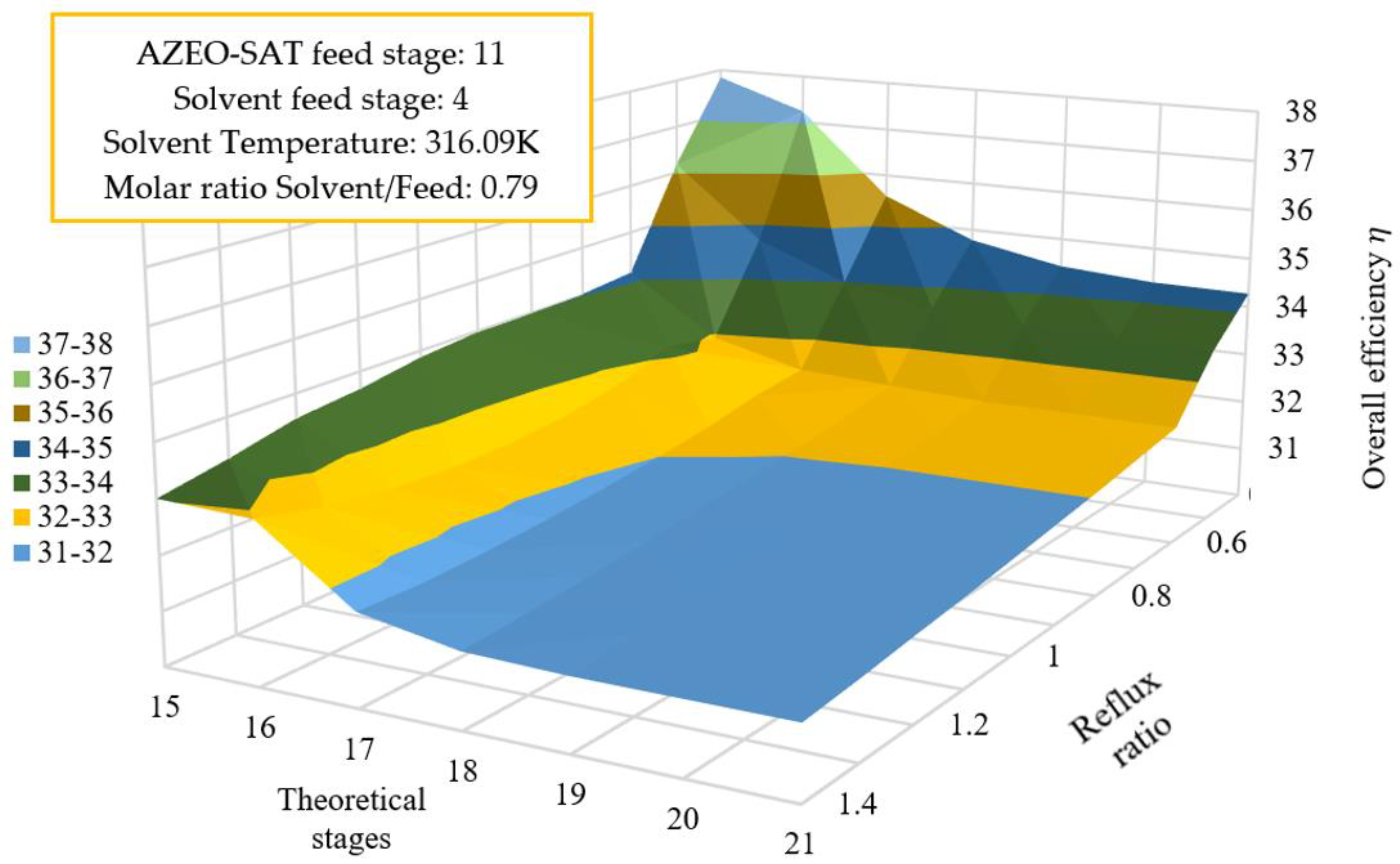
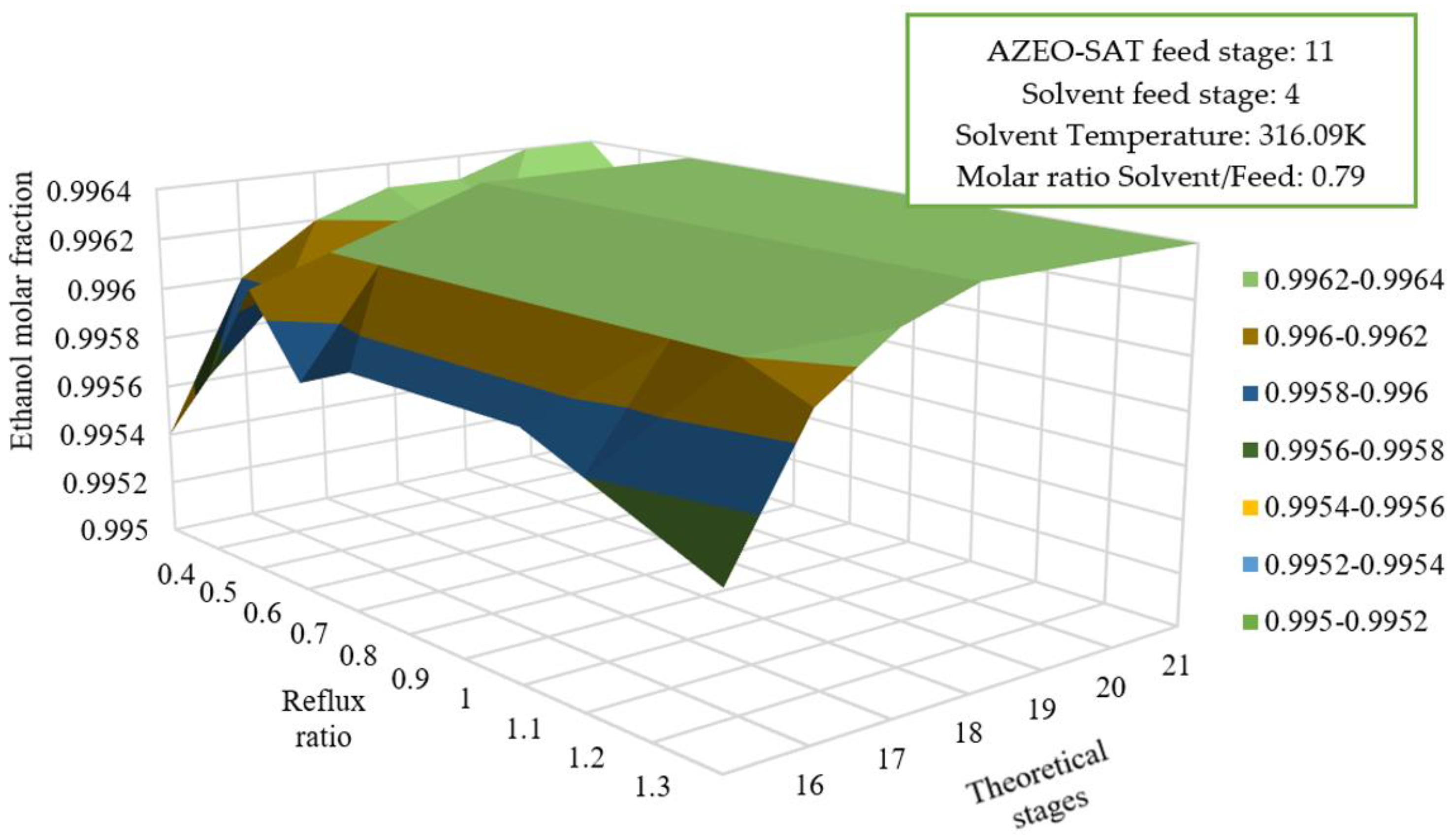
3.5.1. Reflux Ratio Effect, Number of Stages on the Overall Efficiency

Figure 3 shows the variation of the reflux ratio and number of theoretical stages on the overall efficiency of the process. It can be observed that, when decreasing the reflux ratio and number of stages, there is an increase in the overall efficiency of the separation system, which is attributed to the changing reflux ratio manipulating the primary and transformed exergy loads. However, when analyzing Figure 4, at the same point where overall efficiency is high, ethanol concentration decreased compared to what was initially proposed, so this ethanol fraction would not serve the same energy purpose. It is noteworthy that by modifying the number of stages, the extractive distillation column design is being directly acted upon, modifying its local efficiency, but in accordance with what was said above, to increase the overall process efficiency, the local efficiency must be increased. However, this requires restructuring the design of the equipment, in this case the tower, so it is more convenient to act on the exergy load in case the separation plant is in operation.

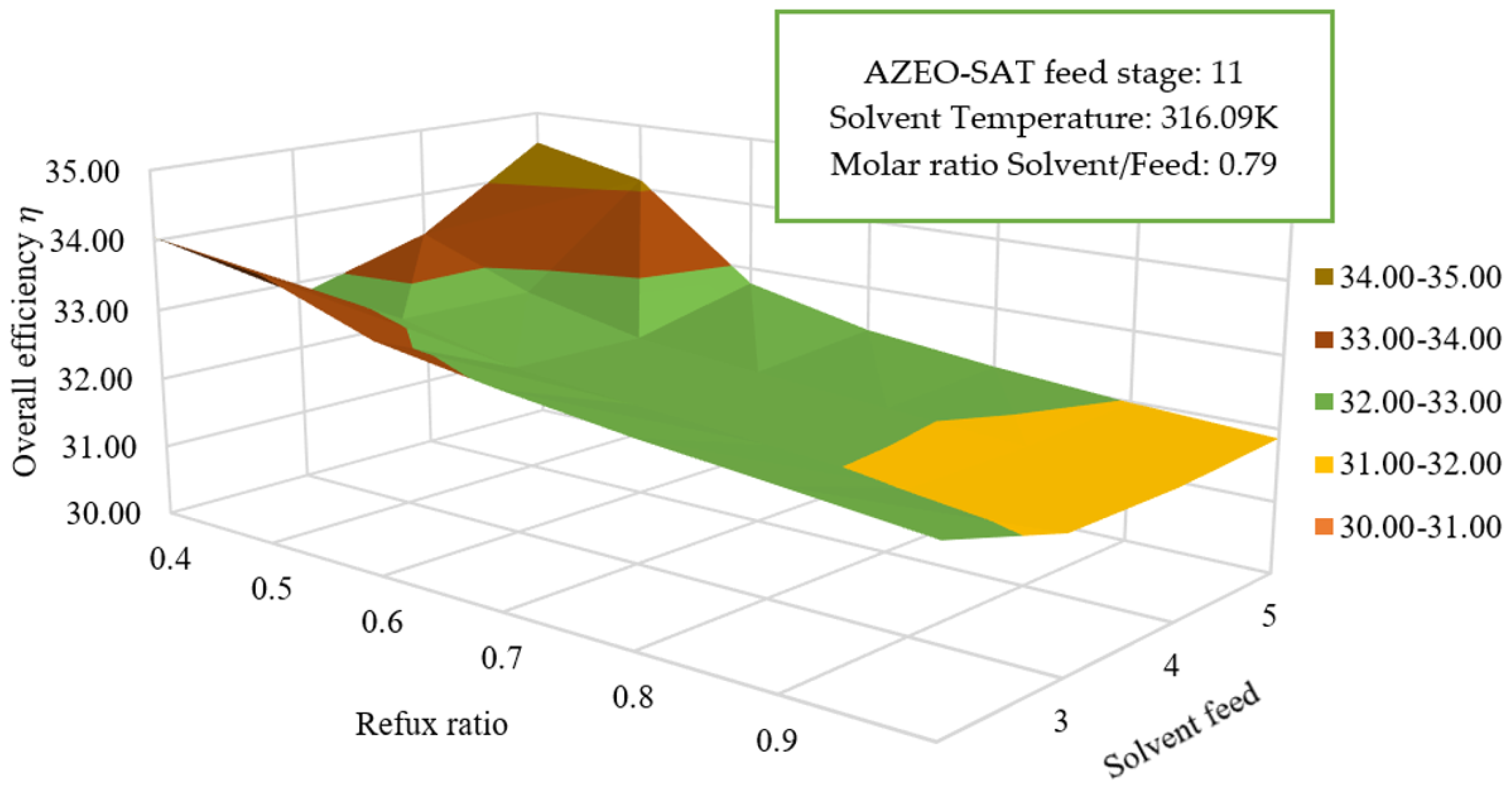
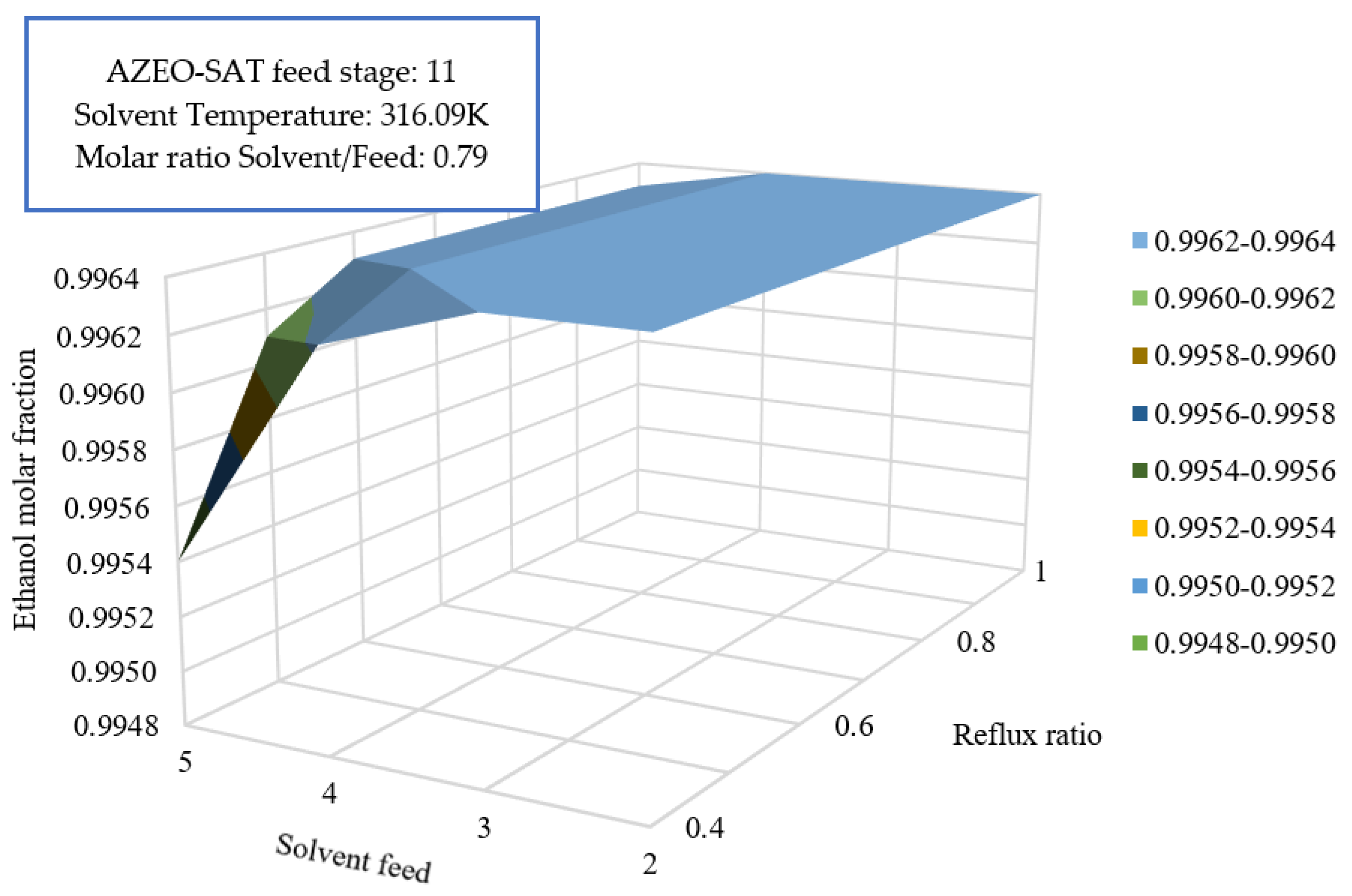
3.5.2. Reflux Ratio Effect and Solvent Feed on Overall Efficiency

Figure 5 shows the variation of the reflux ratio and solvent feed on the overall efficiencies of the process. When performing a variation of the solvent feed and the solvent feed stage on the overall efficiency, there are two points at which the overall efficiency of the system is high. This is because the configuration of the solvent feed and reflux ratios affects the minimum work of the extractive distillation tower [50] and the exergy loads, respectively. This minimum work configuration depends directly on the amount of exergy that enters the tower and its destruction; therefore, if the solvent feed stage changes, there will be a direct impact on minimum work and, at the same time, it will influence local efficiency, causing an increase in global efficiency. For this case, it can be said that for these two points where there is a maximum point of efficiency, there will be an extractive distillation, less exergy destruction, and, therefore, a higher minimum work and a high local efficiency. However, Figure 6 shows that the ethanol composition is not the one specified initially, so it will not be used for energetic purposes either.

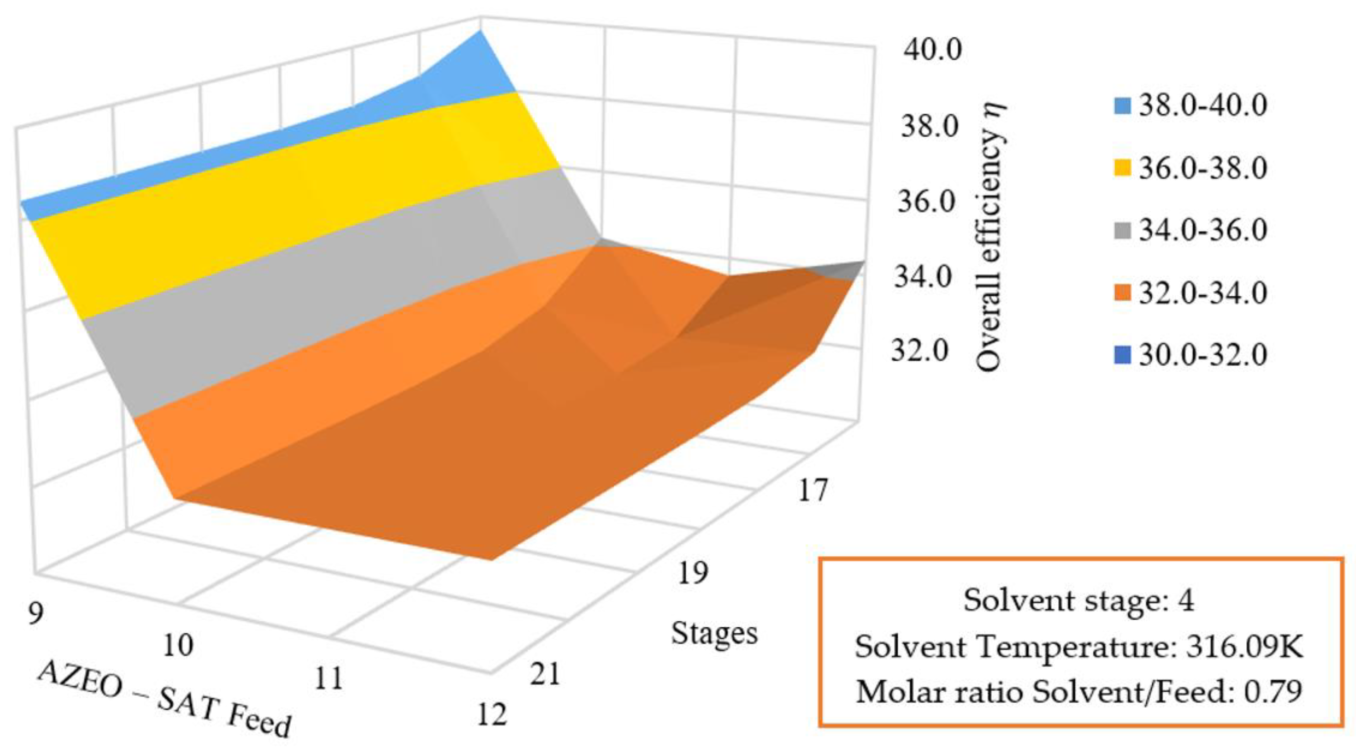
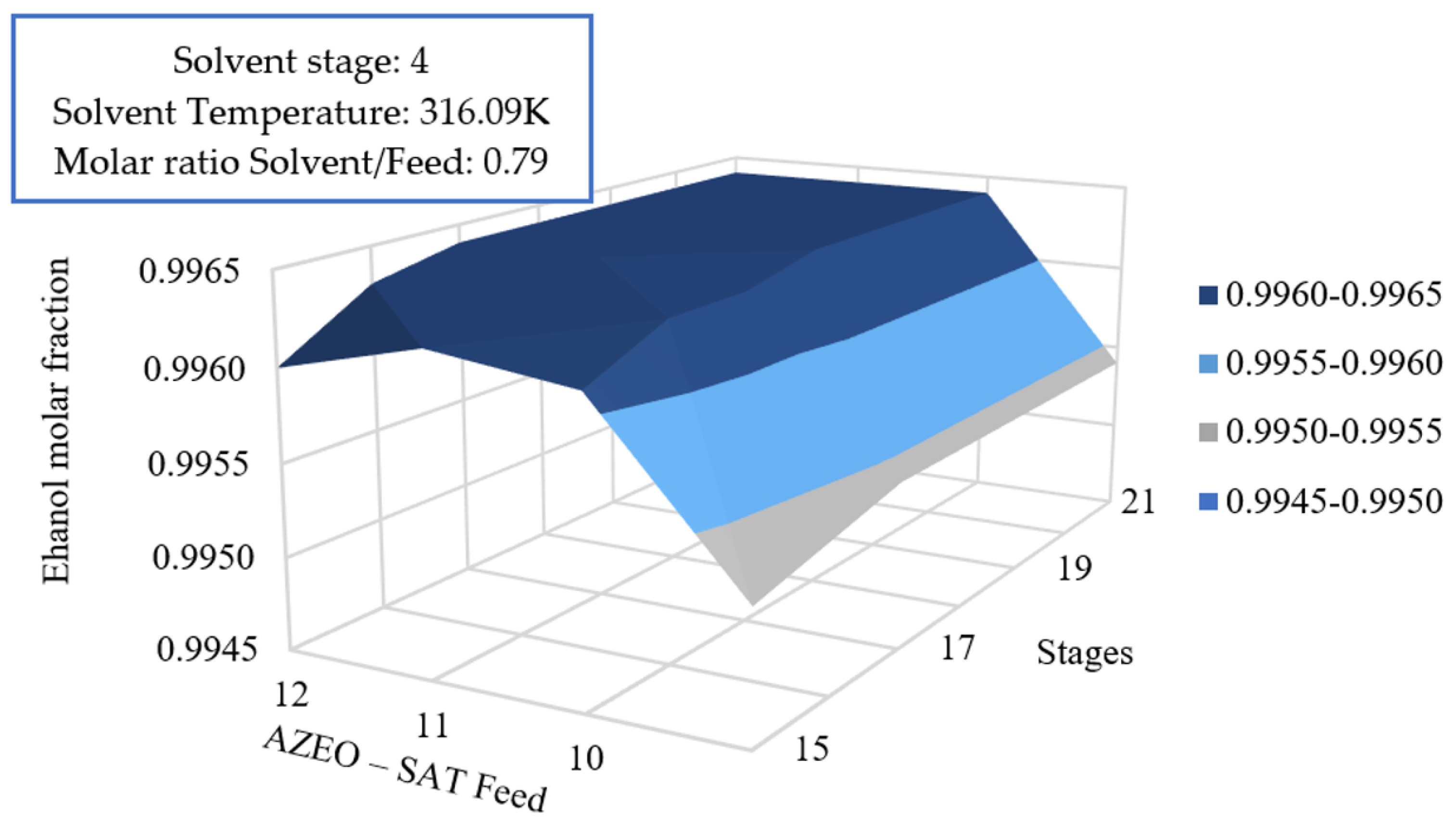
3.5.3. Effect of Azeotrope Feed and Number of Stages on the Global Efficiency

Figure 7 shows the reflux and solvent feed variations on ethanol purity. A series of maximum points of overall efficiency are established by the ninth feeding stage of the azeotrope. However, it is observed that by feeding a mix of ethanol and water to an extractive distillation column, the ethanol purity is lower than the specified value, so it does not work for energetic means (Figure 8). If the mix is fed to the tenth, eleventh, or twelfth stage, the highest overall efficiency is observed, around one percentage point higher, and the ethanol purity will be higher than the specified one. According to Figure 7 and Figure 8, if the azeotrope is fed to the eleventh stage and it is established in the column design that it will have sixteen stages, the overall efficiency of the process will be 33.53% and the ethanol purity will be 99.65%, showing that the manipulation of the extractive distillation column design configuration will involve an improvement in the energetic efficiency of the process. This trend is reported in other investigations, such as the one proposed by Guang et al. (2020) [50], who propose a hetero-azeotropic distillation process of an aqueous azeotropic solution of isopropanol and diisopropylether. Where the thermodynamic efficiency of the process is increased from 19.80% to 25.96%.

4. Conclusions

The implementation of the exergy load distribution method allowed for improving the energy efficiency of the process for dehydration of ethanol by extractive distillation, which allowed for identifying and determining energy wastes that are not seen with a normal analysis. The methodology carried out for the exergy analysis by load distribution is divided into three parts: the calculation of the flow exergy considering the physical and chemical exergies of the distillation process, the calculation of the primary and transformed exergy contribution considering the consumed exergy, and finally the overall process efficiency, which shows the real percentage of energy being used in the process. In the present study, it is observed that initially, the overall efficiency of the extractive distillation process was 30.67%, with azeotrope feed at stage 11, solvent feed at stage 4, and reflux ratio of 0.65. By performing the sensitivity analysis and modifying the reflux ratio in 0.5, with the solvent feed at stage 5 and the azeotrope feed at stage 13, an improvement of exergy overall efficiency of 33.53% was obtained. This led to a considerable improvement in the local efficiency of column C1 and the destroyed exergy was usable in the process, decreasing the energy consumed.
By combining the thermodynamic criteria with the analysis of the results presented, it was found that it is better to manipulate the design and configuration of the extractive distillation column than the energetic loads, which correspond to the flows of matter entering the column. This means that in the process design, it is very useful to consider this combined energetic and sensitivity analysis, as it allows the identification of critical operations that need to be improved. In a case where the process is already in operation, this analysis allows the identification of conditions and relationships of matter flows that allow an improvement in the energy use in the system. In future work, we intend to apply the methodology and criteria discussed in this study to salt extractive distillation processes and dividing wall distillation columns, coupled with the thermoeconomic assessment.

Author Contributions

Conceptualization, E.D.V.D. and L.E.G.-M.; Data curation, F.A.d.S.F., V.J.C.G. and W.L.e.S.; Formal analysis, J.E.A.-C., H.A.M.-S., W.L.e.S. and E.D.V.D.; Funding acquisition, C.A.G.-M. and F.A.d.S.F.; Methodology, J.S.F.-R., J.E.A.-C., H.A.M.-S. and V.J.C.G.; Project administration, C.A.G.-M., J.E.A.-C., H.A.M.-S., E.D.V.D. and L.E.G.-M.; Resources, F.A.d.S.F., V.J.C.G., L.E.G.-M. and E.F.L.; Software, J.S.F.-R., J.E.A.-C., H.A.M.-S. and W.L.e.S.; Supervision, V.J.C.G. and E.F.L.; Validation, J.S.F.-R. and J.E.A.-C.; Visualization, C.A.G.-M. and V.J.C.G.; Writing—original draft, J.S.F.-R., J.E.A.-C., H.A.M.-S. and E.F.L.; Writing—review and editing, J.S.F.-R., J.E.A.-C., C.A.G.-M., F.A.d.S.F., W.L.e.S., E.D.V.D., L.E.G.-M. and E.F.L. All authors have read and agreed to the published version of the manuscript.

Funding

This research received no external funding.

Data Availability Statement

Not applicable.

Acknowledgments

This work was supported for publication by PROPESP/UFPA (PAPQ).

Conflicts of Interest

The authors declare no conflict of interest.

References

  1. Altayeb, R.K. Liquid Fuel Production from Pyrolysis of Waste Tires: Process Simulation, Exergetic Analysis, and Life Cycle Assessment; American University of Sharjah: Sharjah, United Arab Emirates, 2015. [Google Scholar]
  2. Veksha, A.; Giannis, A.; Chang, V.W. Conversion of non-condensable pyrolysis gases from plastics into carbon nanomaterials: Effects of feedstock and temperature. J. Anal. Appl. Pyrolysis 2017, 124, 16–24. [Google Scholar] [CrossRef]
  3. Chernova, N.I.; Kiseleva, S.V.; Larina, O.M.; Sytchev, G.A. Manufacturing gaseous products by pyrolysis of microalgal biomass. Int. J. Hydrogen Energy 2019, 45, 1569–1577. [Google Scholar] [CrossRef]
  4. Lestinsky, P.; Palit, A. Wood pyrolysis using aspen plus simulation and industrially applicable model. GeoSci. Eng. 2016, 62, 11. [Google Scholar] [CrossRef]
  5. Klinger, J.L.; Westover, T.L.; Emerson, R.M.; Williams, C.L.; Hernandez, S.; Monson, G.D.; Ryan, J.C. Effect of biomass type, heating rate, and sample size on microwave-enhanced fast pyrolysis product yields and qualities. Appl. Energy 2018, 228, 535–545. [Google Scholar] [CrossRef]
  6. Alalwan, H.A.; Alminshid, A.H.; Aljaafari, H.A.S. Promising evolution of biofuel generations. Subject review. Renew. Energy Focus 2019, 28, 13. [Google Scholar] [CrossRef]
  7. IEA Biofuels. Renewables 2021. Available online: https://www.iea.org/reports/renewables-2021/biofuels?mode=transport&region=World&publication=2021&flow=Consumption&product=Ethanol (accessed on 2 January 2023).
  8. IEA Transport Biofuels. Renewable Energy Market Update—May 2022. Available online: https://www.iea.org/reports/renewable-energy-market-update-may-2022/transport-biofuels (accessed on 2 January 2023).
  9. Joseph, A.; Tulasi, Y.; Shrivastava, D.; Kiran, B. Techno-economic feasibility and exergy analysis of bioethanol production from waste. Energy Convers. Manag. X 2023, 18, 100358. [Google Scholar] [CrossRef]
  10. Gil, I.; Gómez, J.; Rodríguez, G. Control of an extractive distillation process to dehydrate ethanol using glycerol as entrainer. Comput. Chem. Eng. 2012, 39, 129–142. [Google Scholar] [CrossRef]
  11. Gil, I.; García, L.; Rodríguez, G. Simulation of ethanol extractive distillation with mixed glycols as separating agent. Braz. J. Chem. Eng. 2014, 31, 259–270. [Google Scholar] [CrossRef]
  12. Lauzurique, G.; Zumulacáguerri, L.; Pérez, O.; Curbelo, A. Simulación de la destilación extractiva para la obtención de etanol anhidro empleando glicoles. Sci. Teach. Technol. 2016, 53, 362–383. [Google Scholar]
  13. Batista, E.; Meirelles, A. Simulation and thermal integration SRV in extractive distillation column. J. Chem. Eng. Japan 1997, 30, 45–51. [Google Scholar] [CrossRef]
  14. Sorin, M.; Brodyansky, V. A method for thermodynamic optimization—I theory and application to an ammonia synthesis plant. Energy 1992, 17, 1019–1031. [Google Scholar] [CrossRef]
  15. Sorin, M.; Bonhivers, J.; Paris, J. Exergy efficiency and conservation of chemical reactions. Energy Convers. Manag. 1998, 39, 1863–1868. [Google Scholar] [CrossRef]
  16. Sorin, M.; Bonhivers, J.; Paris, J. Integrated exergy load distribution method and pinch analysis. Comput. Chem. Eng. 1999, 23, 497–507. [Google Scholar] [CrossRef]
  17. Sorin, M.; Hammache, A.; Diallo, O. Exergy Load Distribution Approach for Multi-step Process Design. Appl. Therm. Eng. 2000, 20, 1365–1380. [Google Scholar] [CrossRef]
  18. Moran, M.; Shapíro, H.; Boettner, D.; Bailey, M. Fundamentals of Engineering Thermodynamics; John Wiley Sons: New York, NY, USA, 2014. [Google Scholar]
  19. Luis, P. Exergy as a tool for measurement process intensification in chemical engineering. J. Chem. Technol. Biotechnol. 2013, 88, 1951–1958. [Google Scholar] [CrossRef]
  20. Cengel, Y.; Boles, M. Termodinámica; Mc Graw Hill Education: México, Mexico, 2011. [Google Scholar]
  21. Fernández, J. Análisis Termoeconómico de un Proceso de Producción de Biodiesel que Opera de Manera Convencional y oor Destilación Reactiva, Tesis (Grado en Ingeniería Química), Facultad de Ingeniería, Programa de Ingeniería Química; Fundación Universidad de América: Bogotá, Colombia, 2018. [Google Scholar]
  22. Bylka, J.; Mróz, T. Exergy evaluation of a water distribution system. Energies 2020, 13, 6221. [Google Scholar] [CrossRef]
  23. Kallio, S.; Siroux, M. Exergy and energy-economic approach to evaluate hybrid renewable energy systems in buildings. Energies 2023, 16, 1029. [Google Scholar] [CrossRef]
  24. Zhang, L.; Zhai, H.; He, J.; Yang, F.; Wang, S. Application of exergy analysis in flue gas condensation waste heat recovery systems evaluation. Energies 2022, 15, 7525. [Google Scholar] [CrossRef]
  25. Khoobbakht, G.; Kheiralipour, K.; Rasouli, H.; Rafiee, M.; Hadipour, M.; Karimi, M. Experimental exergy analysis of transesterification in biodiesel production. Energy 2020, 196, 117092. [Google Scholar] [CrossRef]
  26. Ortiz, P.; Marechal, F.; Oliveira, J. Exergy assessment and techno-economic optimization of bioethanol production routes. Fuel 2020, 279, 118327. [Google Scholar] [CrossRef]
  27. Meramo-Hurtado, S.; González-Delgado, A.; Rehmann, L.; Quiñones-Bolaños, E.; Mehrvar, M. Comparison of Biobutanol Production Pathways via Acetone–Butanol–Ethanol Fermentation Using a Sustainability Exergy-Based Metric. ACS Omega 2020, 5, 18710–18730. [Google Scholar] [CrossRef] [PubMed]
  28. Zhang, H.; Guo, C.; Jiao, Y.; Liu, X.; He, C.; Awasthi, M.; Liu, L.; Chang, C. Exergy analysis and optimization of bio-methane production from corn stalk pretreated by compound bacteria based on genetic algorithm. Bioresour. Technol. 2022, 346, 126413. [Google Scholar] [CrossRef] [PubMed]
  29. Zhang, Y.; Li, L.; Xu, P.; Liu, B.; Shuai, Y.; Li, B. Hydrogen production through biomass gasification in supercritical water: A review from exergy aspect. Int. J. Hydrogen Energy 2019, 44, 15727–15736. [Google Scholar] [CrossRef]
  30. Ayala-Ruíz, N.; Malagón-Romero, D.; Milquez-Sanabria, H. Exergoeconomic evaluation of a banana waste pyrolysis plant for biofuel production. J. Clean. Prod. 2022, 359, 132108. [Google Scholar] [CrossRef]
  31. Vilardi, G.; Verdone, N. Exergy analysis of municipal solid waste incineration processes: The use of O2-enriched air and the oxy-combustion process. Energy 2022, 239, 122147. [Google Scholar] [CrossRef]
  32. Mehrpooya, M.; Khalili, M.; Sharifzadeh, M. Model development and energy and exergy analysis of the biomass gasification process (Based on the various biomass sources). Renew. Sustain. Energy Rev. 2018, 91, 869–887. [Google Scholar] [CrossRef]
  33. Singh, R.; Jena, K.; Chakraborty, J.; Sarkar, A. Energy and exergy analysis for torrefaction of pigeon pea stalk (cajanus cajan) and eucalyptus (eucalyptus tereticornis). Int. J. Hydrogen Energy 2020, 45, 18922–18936. [Google Scholar] [CrossRef]
  34. Balat, M.; Balat, M.; Kırtay, E.; Balat, H. Main routes for the thermo-conversion of biomass into fuels and chemicals. Part 1: Pyrolysis systems. Energy Convers. Manag. 2009, 50, 3147–3157. [Google Scholar] [CrossRef]
  35. García-García, J.; Marmolejo-Correa, D.; Cárdenas-Guerra, J.; Morales-Rodríguez, R. Exergy analysis of an extractive distillation column for reducing energy consumption in a bioethanol production process. Comput. Aided Process Eng. 2018, 43, 513–518. [Google Scholar] [CrossRef]
  36. Sato, N. Chemical Energy An Exergy: An Introduction to Chemical Thermodynamics for Engineers; Elsevier Science: Amsterdam, The Netherlands, 2004. [Google Scholar]
  37. Liang, X.; Liu, Y.; Kang, L. Retrofit and optimization for vacuum gas oil hydrotreating system based on exergy load distribution analysis. Int. J. Exergy 2016, 21, 347–368. [Google Scholar] [CrossRef]
  38. Uyazán, A.; Gil, I.; Aguilar, J.; Rodríguez, G.; Caicedo, L. Producción de alcohol carburante por destilación extractiva: Simulación del proceso con glicerol. Rev. Ing. Investig. 2006, 26, 45–50. [Google Scholar]
  39. Meirelles, A.; Weiss, S.; Herfurth, H. Ethanol dehydration by extractive distillation. J. Chem. Technol. Biotechnol. 1992, 53, 181–188. [Google Scholar] [CrossRef]
  40. Szargut, J. Exergy Method: Technical and Ecological Applications; WIT Press: Southampton, UK, 2005. [Google Scholar]
  41. Kotas, T. Exergy Method of Thermal Plant Analysis; Butterwoth-Heinemann: Oxford, UK, 1985. [Google Scholar]
  42. Demirel, Y. Nonequilibrium Thermodynamics Transport and Rate Processes in Physical, Chemical and Biological Systems; Elsevier Science: Amsterdam, The Netherlands, 2007. [Google Scholar]
  43. Ghannadzadeh, A. Exergetic Balances and Analysis in a Process Simulator: A Way to Enhance Process Energy Integration. Ph.D. Thesis, Departamento de Ingeniería de Procesos y Medio Ambiente, Universidad de Toulouse, Toulouse, France, 2012. Available online: https://oatao.univ-toulouse.fr/9613/1/ghannadzadeh.pdf (accessed on 19 December 2022).
  44. Kanoglu, M.; Dincer, I.; Rosen, M. Understanding energy and exergy efficiencies for improved energy management in power plants. Energy Policy 2007, 35, 3967–3978. [Google Scholar] [CrossRef]
  45. Boyaghchi, F.; Molalei, H. Sensitivity analysis of exergy destruction in a real combined cycle power plant based on advanced exergy method. Energy Convers. Manag. 2015, 99, 374–386. [Google Scholar] [CrossRef]
  46. Demirel, Y. Thermodynamic analysis of separation systems. Sep. Sci. Technol. 2010, 39, 3897–3942. [Google Scholar] [CrossRef]
  47. Cano, N.A.; Céspedes-Zuluaga, S.; Guerrero-Martin, C.; Gallego, D. Exergy and emergy: Complementary tools for assessing the environmental sustainability use of biosolids generated in wastewater-treatment plant for energy-production. Química Nova 2022, 45, 4–15. [Google Scholar] [CrossRef]
  48. Ibañez-Gómez, L.F.; Albarracín-Quintero, S.; Céspedes-Zuluaga, S.; Montes-Páez, E.; Ando, O.H., Jr.; Carmo, J.P.; Guerrero-Martin, C.A. Process optimization of the flaring gas for field applications. Energies 2022, 15, 7655. [Google Scholar] [CrossRef]
  49. Cante Soler, C.A.; Guerrero Martin, C.A.; Malagueta, D.C. Feasibility of the Implementation of Solar Thermal Energy in Steam Assisted Gravity Drainage (Sagd) for Extra Heavy Oil Field in Colombia. Geoenergy Sci. Eng. 2023, 222, 211463. [Google Scholar] [CrossRef]
  50. Guang, C.; Shi, X.; Zhao, X.; Zhang, Z.; Li, G. Development and intensification of a four-column hybrid process of heteroazeotropic distillation and pressure-swing distillation. Chem. Eng. Process. Process Intensif. 2020, 150, 107875. [Google Scholar] [CrossRef]
Figure 1. Scheme of the extractive distillation separation system. Source: the authors.
Energies 16 03502 g001
Figure 2. Exergy balance in the process of obtaining fuel ethanol (the boxes in red show the percentage contribution to total exergy, the green stripes are the control volume to which the exergy balance is applied and the blue arrows are the exergy currents of the process). Source: the authors.
Energies 16 03502 g002
Figure 3. Variation of the reflux ratio and number of theoretical stages on the overall efficiency of the process.
Energies 16 03502 g003
Figure 4. Reflux ratio variation and the number of theoretical stages on the purity of ethanol.
Energies 16 03502 g004
Figure 5. Variation of reflux ratio and solvent feed on the overall efficiencies of the process.
Energies 16 03502 g005
Figure 6. Reflux ratio and solvent feed variation on ethanol purity.
Energies 16 03502 g006
Figure 7. Variation of the azeotrope feed and the number of stages on the overall efficiency of the process.
Energies 16 03502 g007
Figure 8. Variation of the azeotrope feed and the number of stages on ethanol purity.
Energies 16 03502 g008
Table 1. Energy consumption of the extractive distillation process.
Energy Consumption (kJ/kg ethanol)
(C1)(C2)Uzayan [38] (C1)Uzayan [38] (C2)
12773251249224
Table 2. Exergy flow in each of the process streams.
Stream E ˙ f i   ( kJ / s ) E ˙ x i   ( kJ / s ) E ˙ i s   ( kJ / s )
AZE032,012.5632,012.56
SOLV-REC23.5326,415.1626,438.69
AZEO-SAT17.4432,012.5632,030
RECSOLVH1.9926,415.1626,417.16
MAKE-UP0.174309.03309.27
ENTRAIN3.58126,710.7426,714.32
ETOH0.327332,036.5932,036.9
MIX86.9526,684.8526,771.81
WATER122.3308.6430.9
SOLV22.4926,415.5626,438.66
Table 3. Destroyed exergy in each operation.
Destroyed Exergy kJ/s
H2.8
Pump0.3
Mixer0.6
Column C1413.7
Column C2118.4
Table 4. Results of the exergy load distribution method.
Separation System by Extractive Distillation
Coefficients (%)HPumpMixerC1C2
λ p , i 2.460.020200.174338.6658.68
λ t , i 00.020200.174300
η i 80.9519.7899.913.4942.62
η 30.67
Disclaimer/Publisher’s Note: The statements, opinions and data contained in all publications are solely those of the individual author(s) and contributor(s) and not of MDPI and/or the editor(s). MDPI and/or the editor(s) disclaim responsibility for any injury to people or property resulting from any ideas, methods, instructions or products referred to in the content.

