1. Introduction
Adiponitrile is an important chemical intermediate used in producing hexanediamine (one of the primary raw materials of nylon 66) and other fine chemicals and organic synthesis fields [
1]. Waste liquid is produced when adiponitrile is synthesized by direct cyanidation of butadiene, which consists of adiponitrile isomers, 3-pentenenitrile, and hydrogen cyanide [
2]. The waste liquid needs to be treated before it can be discharged, and in the long run, the economic benefit of burning waste liquid is more excellent than other treatment methods. Liquid fuel can be burned efficiently after atomization. Atomization can divide the liquid jet into multiple particles, enhance gas–liquid mixing, improve the contact surface area of liquid and combustion-supporting gas, and improve combustion performance. The viscosity of adiponitrile waste liquid from a chemical plant is 1000–2000 cp, and it has the characteristics of complex composition, large flow rate, and unstable flow rate. The chemical plant tried to increase the temperature and use the ultrasonic wave to reduce the viscosity of the waste liquid, and replaced a variety of nozzles, but there are still some problems in the actual production, such as nozzle blockage, liquid agglomeration, poor gas–liquid mixing and so on. Currently, no atomizers can atomize adiponitrile waste liquid with high quality, so this paper tries to solve this problem.
The atomization mechanism and atomizer structure of low-viscosity liquids such as water and gasoline have been widely studied. Eggers and Dumouchel et al. classified atomization as fluid jet dynamics, and they have uniformly described and summarized atomization’s basic concepts and formulas [
3,
4]. Aalburg has studied viscosity change’s effect on the liquid jet’s breakup process and believes that when Ohnesorge Number (Oh) is greater than 1, the atomization process of high-viscosity liquid may change dramatically. It will be challenging to use experiments to assist the study [
5]. Li et al. carried out further research. They used AMR technology to simulate the breaking process of a high-viscosity liquid jet and compared the fluid jet breaking process of Oh = 0.004 and Oh = 2. They found that Oh would delay the time of liquid column deformation and ligament breakage, and they pointed out that higher viscosity will lead to larger droplet diameter [
6].
Atomization is a complex process. From the perspective of forces, the multiple forces acting on the liquid during breaking can be divided into external and internal forces. External forces are forces exerted by gravity, other fluids, or mechanical structures, and internal forces refer to viscous forces and surface tension. The viscous force prevents the deformation of the liquid, and the surface tension keeps the liquid spherical to make the liquid have the minimum surface area. When the external force of the liquid is greater than the internal force, the liquid begins to break when the force is unstable. The viscosity of adiponitrile waste liquid is about 1000 cp, and the Oh is about 1.94, so it is a high-viscosity liquid, and its viscous force is much greater than the surface tension.
From the perspective of the mechanism, the instability mechanism of liquid fragmentation mainly includes the Rayleigh–Taylor instability and the Kelvin–Helmholtz instability. Among them, the R-T instability is caused by the normal velocity gradient of the phase interface between different density fluids, and the K-H instability is caused by the tangential velocity gradient of the phase interface between gas and liquid [
7].
From the perspective of the process, the liquid breakup usually goes through a primary breakup and a secondary breakup. The liquid jet or liquid film will be broken into liquid filaments or flakes in the primary breakup. The fluid disturbances, such as small changes in velocity within the liquid, will gradually increase under fluid instability until these disturbances are enough to break the linear and flaky liquid into smaller ripple shapes. This process determines the detailed characteristics of the liquid spray’s form, structure, and droplet size distribution. In the secondary breakup, the large droplets and ripple-like liquids produced in the primary breakup are further decomposed into smaller droplets under the action of external and internal forces.
The atomization of viscous liquid is a long-term problem in the field of nozzle atomization. Currently, the main types of atomizers for high-viscosity liquids are pneumatic atomization nozzles and splash plate nozzles. Among them, the splash plate nozzle is mainly used to atomize the black liquor produced in the process of sulfate recovery. Pneumatic atomization nozzles, also known as two-fluid nozzles, can be divided into air-assisted, air-jet, and foam nozzles. A paint spray gun is a typical single-channel pneumatic atomizer for high-viscosity liquid, and the viscosity of paint is generally at 10–3000 cp, and the flow rate is less than 20 g/s. The nozzle designed in this paper can be used to atomize chemical waste liquid with a viscosity of about 1000 cp and a flow rate greater than 420 g/s. The basic structure of the nozzle comes from Li [
8]. They designed a coaxial three-channel nozzle and studied its performance in atomizing 762 cp glycerol under reverse pressure. The practicability of the nozzle was verified by experiment and simulation. A two-stage supersonic steam atomizer is presented in this paper. The atomization medium is the high-temperature saturated steam which can be easily provided in the chemical plant. The saturated steam will heat the waste liquid continuously in the pipe for about 1 m before the nozzle exit to reduce the waste liquid viscosity as much as possible. Then the Laval nozzle accelerates the saturated steam to supersonic speed, violently impacts the liquid, and finally achieves the purpose of atomization. To cope with the possibility of higher viscosity and higher flow of chemical waste liquid in the future, engineers need to design a variety of nozzles with similar structures. To shorten the time to verify the rationality of these nozzles, an economical and convenient computer simulation scheme should be explored to improve the economy. Using the VOF-DPM model for atomization simulation is an alternative that can significantly reduce the computational cost [
9].
At least three methods in Fluent can be utilized for atomization simulation. The first method is the VOF coupling surface tension model, which has been used by many scholars for atomization simulation but requires fine grids and many computing resources. This method is compatible with many turbulence models, such as k-ω and LES [
10]. After using appropriate UDF, it can also be coupled with DPM or other models to complete the simulation of secondary breakup. The second method focuses on phase interface tracking and uses the Coupled Level-set and volume of flow (CLSVOF) model, but CLSVOF is poorly compatible with continuous surface tension models [
11].
The third method is the VOF-DPM two-way coupling model, which can be used to improve the computational efficiency of atomization simulation. Since the appearance of Fluent 19.1, this method can be used to simulate the complete transformation process of liquid from continuous phase to discrete phase and is compatible with the continuous surface tension model. The VOF model predicts the initial jet and the primary breakup process, and the DPM model tracks the droplet trajectory and secondary breakup process, the VOF-DPM combines the advantages of two models and is a suitable calculation model for the study of jet breakup and liquid atomization [
12]. According to the set parameters standards such as minimum liquid mass diameter and asphericity, the solver can select the liquid blocks that can be converted from the VOF-DPM model and remove them from the VOF solver and convert them to the point mass in the Lagrange formula. Converting the liquid block to a discrete phase does not impose a volume change on the flow simulation of the continuous phase. Still, it creates a gas phase volume that is the same as the liquid phase volume in the VOF simulation, which can avoid the false momentum source in the conversion process and maintain the volume conservation. The converted droplets no longer need the fine grids, and if the Automatic Mesh Adaption in Fluent is used to coarsen the grid, the computational cost can be saved. At present, a small amount of literature has reported the use of VOD-DPM for simulation. The Schtze and Sami teams have verified that the VOF-DPM model can accurately forecast an air transverse jet’s SMD and droplet size distribution [
13,
14]. In addition, the conclusions of many papers also support the reliability of the VOF-DPM model provided by Fluent [
9,
15]. The reverse transition mechanism, namely DPM-to-VOF, has also been verified to be consistent with the experimental results of droplet film formation [
16]. However, there is little literature about applying the VOF-DPM model to simulate the atomization of high-viscosity liquid.
2. Geometry and Mesh
The basic structure of the nozzle is a coaxial three-channel nozzle for atomizing glycerol, and the core part is a three-layer casing structure. Considering that the viscosity of adiponitrile waste liquid is about 1.25 times that of glycerol, this paper’s coaxial three-channel nozzle is improved. The central gradually shrinking nozzle is changed into a Laval nozzle [
17,
18], and the thickness of the casing diaphragm and the length of the mixing chamber is adjusted according to the steady-state calculated velocity flow field, so that the high-viscosity waste liquid can be ejected and atomized normally with the steam. Before we performed the transient simulation in this article, we carried out some simple steady-state simulations to preliminarily verify the nozzle structure’s rationality. Limited by space, this article does not describe the specific process of steady-state simulation.
Figure 1 and
Table 1 show the basic structural parameters of the nozzle. The nozzle is a simple three-layer casing structure. The innermost fluid is first-stage steam, the middle fluid is high-viscosity waste liquid, and the outermost fluid is second-stage steam. The first-stage steam will enter the Laval nozzle and accelerate to about Mach 1.5, where the divergent tube is very short. Then the first-stage steam will flow through a straight pipe and enter the mixing chamber, and the flow channels of the waste liquid and second-stage steam are gradually shrinking sleeves. After the injection of the nozzle, the first-stage steam and the waste liquid flow out of the mixing chamber at high speed. Then the second-stage steam will impact the waste liquid from the side, and finally, the waste liquid and steam flow out gradually. In order to improve the calculation efficiency, as shown in
Figure 2, only the internal fluid domain of the nozzle and a small part of the combustion chamber fluid domain are taken as the calculation model, these fluid domains are the core areas where atomization breakup occurs, and the calculation cost is saved.
In the actual combustion chamber, the medium used to atomize the waste liquid is steam, the fuel is the waste liquid, and the oxidant is the pre-heated air. Primary and secondary air will enter the furnace downstream of the nozzle to participate in the combustion. However, in this article, we try to focus on atomization simulation, and no air will appear in the simulations in this article.
Regarding the mesh, due to the high flow rate of steam and clear mainstream direction, it is very suitable for drawing hexahedral mesh. Select Space Claim 22.1 software to draw a geometric model and divide the hexahedral structured grid. High-viscosity waste liquid flows slowly under the effect of the viscosity of the wall, Re is less than 200, and the grid requirements are lower. However, the pressure and speed of the steam are tremendous, leading to the Re exceeding 26,000, so the grid encryption is applied in the Laval nozzle and the hybrid ventricular fluid domain.
In this paper, the steam velocity exceeds 600 m/s, so for the transient simulation of high-speed fluid, we should try to ensure that the Courant Number is not more than 2. The Courant Number represents the ratio of the time step size to the characteristic time required for the fluid to flow through a local grid. In the one-dimensional grid, the Courant Number can be expressed as follows:
Here, u is the fluid velocity (m/s); Δt is the time step (s); Δx is the local grid size (m).
The VOF model cannot track liquid blocks smaller than mesh, so the minimum size of the grid depends on the size of the minimum droplet that may be generated. Considering the limitation of Courant Number, it is not easy to control the computational cost of hypersonic steam atomization simulation. If tiny droplets (about 50 μm) need to be tracked, a fine grid (less than 50 μm), a large number of grids, and a small time step (about 1 × 10⁻⁷ s) are required. Therefore, in this article, to balance the accuracy and economy, AMR technology is applied to the gas-liquid phase interface area.
Two Field Variable Registers are created in Cell Registers to record the meshes that need to be refined and coarsened. The settings of the two registers are similar. The refinement register and coarsening register will filter out all grids whose curvature of Liquid Volume Fraction is greater than 0.005 and less than 0.001, respectively. The values of Volume Fraction will scale by Global Maximum. Considering that the variable curvature of the liquid phase volume fraction is large, a level 2 transition layer is selected. The adaptive frequency of the grid is set to step by step every two times. In the calculation of this article, the maximum number of grids after the grid adaptive step is about 5,000,000, which has a high economy.
Set the AMR maximum refinement level to level 3, which means that a hexahedral mesh will be refined to 512 meshes at most when needed (
Figure 3). To prevent the number of meshes from rising too fast, the minimum mesh length of AMR is limited to 0.05 mm. These settings make the simulation accuracy of the VOF gas–liquid interface independent of the initial meshes.
However, the VOF interface will not appear in the Laval nozzle, and the AMR will not be applied, so it is still necessary to verify its grid independence. As shown in
Figure 4, five schemes with a different number of grids are selected. Under the same steam inlet absolute pressure, the variation trend of fluid Mach number along the axial distance is obtained. At the critical nozzle exit (44 mm), the grid number of 100,000 and 200,000 fluctuates considerably compared with other schemes. Schemes with a mesh number of 800,000 or more are more stable and close to the theoretical calculation value. In order to balance the calculation accuracy and economy, a scheme with a grid number of 800,000 is selected (
Figure 5).
Figure 6 is the contour of the grid and liquid phase volume fraction in the mixing chamber when the steam inlet absolute pressure is 1.1 MPa and the flow time is 0.1 ms and 1.0 ms. Due to the application of AMR technology, the grid is automatically refined at the gas–liquid interface. The refined hexahedral mesh remains regular, and the mesh direction is still consistent with the mainstream direction of the fluid.
3. Numerical Methods
3.1. Governing Equations
In this paper, the governing equations involved in simulating liquid atomization and breakup are mass, momentum, energy, and continuity equations [
19] as follows:
Here, is the density , is the time , is the velocity vector , is the scalar pressure , is the viscous stress tensor, is the gravitational acceleration (), is the volume surface tension (), is the total energy (), is the temperature , is the specific heat capacity , is the heat flux density of heat conduction . In the VOF model, the values of and in Equations (2)–(4) are weighted by the volume fraction of each phase. , , and are the volume fraction, density, and velocity of the phase, respectively.
3.2. Turbulence Models
The transient simulation of jet breakdown requires high accuracy and a well-analytical turbulent flow field. The Re number of the steam in the mixing chamber is more than 28,000, which is in a strong turbulent state. The simulation in this paper also involves high-viscosity liquids and annular jets, so Shear–Stress Transport (SST) k-ω Model is used, where SST means that the transport of turbulent shear stress is taken into account when defining turbulent viscosity [
20]. The equations of the SST k-ω model are as follows [
21]:
Here, represents the kinetic energy generation term calculated with the average velocity gradient, represents the density, is the turbulent energy, represents the average turbulent velocity, represents the coordinate component (j = 1, 2, 3, …), represents the special turbulence dissipation, and represents the cross-diffusion term, which serves as the coordination boundary between the standard k-ε model and the standard k-ω model.
3.3. Multiphase Models
The VOF model can track the phase interface between steam and waste liquid [
22]. The momentum equation of each phase in the calculation domain is solved and weighted averaged to obtain a single equation common to each phase. The sum of the volume fractions of each phase in the calculation domain is 1. The VOF model combined with the SST k-ω turbulence model can accurately simulate the breakup process of liquid. However, VOF can only simulate the primary breakup of liquid with high precision, and the DPM model must be added to simulate the secondary breakup of liquid more accurately [
23]. In this paper, the volume fraction tracking mode of VOF chooses the explicit formulation. Compared with the implicit formulation, this formulation has higher numerical accuracy, but the Courant Number seriously constrains it, so it is necessary to set a smaller time step to obtain more stable and accurate results. The explicit VOF formulation depends on time, and the volume fraction is discrete as follows [
9]:
Here, is the index of the last time step, is the volume fraction of the phase, is the density , is the mesh volume , is the volume flow through the grid surface based on the normal velocity, is the mass transfer from phase to phase , is the source term and defaults to 0.
The simulation of surface tension is calculated by the momentum equation based on CSF continuous surface tension model proposed by Brackbill et al. in Equation (6) [
24]. The CSF model regards surface tension as a pressure jump at the phase interface [
25]. The
and
of the fluid are weighted physical parameters, and their values depend on the volume fraction of the two gas–liquid phases.
Here, is the density , is the viscosity , is the velocity vector , is the pressure , is the interface deformation tensor , is the gravity acceleration , is the surface tension coefficient , is the two-phase interface curvature, and is the volume fraction gradient vector which is perpendicular to phase interface.
3.4. Discrete Phase Model
The DPM model uses Euler to describe fluid movements and the Lagrange method to describe particle motion [
26]. This model can track the flow of discrete droplets and the secondary breakup. Considering that the supersonic steam is more disturbed by droplets, the High-Res Tracking of DPM is turned on, and the mesh may be decomposed into tetrahedra when performing DPM computing to provide a more stable particle tracking algorithm. The droplets in the DPM model are different, as shown in the following [
21]:
Here, is the drag force, is the buoyancy force, is the gravitation, is the thermophoresis force, and is the Saffman force, which includes the Basset force and the Magnus force.
DPM particles will exchange heat with the fluid. The heat transfer equation between particle temperature and convective heat transfer on the particle surface is as follows [
20,
25]:
Here, is the particle’s mass , is the particle’s heat capacity , and are the local temperature of the particle and the continuous phase, respectively, is the time , is the particle’s surface area , and is the convective heat transfer coefficient .
Droplets will be affected by Kelvin–Helmholtz and Rayleigh–Taylor instabilities when they flow together with steam, so the secondary breakup of droplets in this paper is simulated by the KH-RT model as Equation (12). This model judges the mode and time of droplet breakup by the disturbance of unstable waves on the liquid surface.
Here, is the breaking time of the droplet , is the acceleration of the droplet in its motion direction , and are the liquid phase density and gas phase density , respectively, is the breaking time constant and usually takes the value 1.
3.5. Model Transition
The traditional atomization simulation (such as CLSVOF) uses the VOF model to simulate the primary breakup. It inputs the droplet parameters into the DPM model for secondary breakup atomization simulation, including position, velocity, temperature, and diameter. This paper uses the VOF-DPM model to complete the two-way coupling and transformation between the two models. The injection created in the DPM model does not produce new particles but is used to store the converted particles. In the VOF-DPM model setting, there are three parameters to determine whether the droplet can be converted. The first parameter is the Volume-Equivalent Sphere Diameter Range [
27], which is used to check the size of the liquid fragments in VOF, which is set to 0–500 μm in this article. The second and third parameters are used to check the shape of the liquid, which are Radius Standard Deviation and Radius-Surface Orthogonality, respectively. This article sets both parameters to 0.5. Set this mechanism to check every five time-steps in the calculation, and only liquid fragments that meet the above three criteria will be converted into DPM particles.
3.6. Solution Solvers
In the actual calculation, due to the complexity of the simulation, the Fixed time step advance type is used first, the Max Iterations Per Time Step is set to 100, the time step is set to 1 × 10
−9 s, the time step is set to 1000, and the flow time is 1 × 10
−6 s after the calculation. Then change the time step advance type to Adaptive and the Total flow time to 1 ms. These will help to have a stable and reliable flow field at the beginning of the simulation. The Autosave function is used to prevent the calculation from crashing. Global Courant Number is set to 1 to avoid the flow distance of high-speed steam exceeding one grid in each time step. Although AMR is used to improve computational efficiency, the cost of atomization simulation in this paper is still high. Two 48-core processors are used for parallel computing, but each case still takes more than 22 h. The VOF-DPM model is used in the atomization simulation of Wen, and the calculation time is as long as one month because the droplet conversion diameter is about 10 μm, which requires a finer grid and smaller time step [
28].
The density model of waste liquid adopts the incompressible model, and the viscosity is set to 1000 cp. The nozzle contains a Laval tube. The simulation of supersonic flow is simplified, and the ideal-gas model is selected as the density model of steam [
17,
29]. The equation of ideal-gas model is as follows [
30]:
Here, represents density , represents pressure , represents gas-law constant , represents temperature .
The waste liquid inlet is selected as the Mass-Flow-Inlet, the absolute total pressure is 501,325 Pa, the liquid phase mass flow rate is set to 1500 kg/h, and the temperature is set to 150 °C. The two streams of steam are selected as the Pressure-Inlet, the absolute total pressure is set to 1,128,177.2 Pa, and the temperature is set to the saturation temperature of 188 °C. The absolute total pressure of the Pressure-Outlet is set to 101,325 Pa. The operating pressure is set to 0 Pa.
Table 2 summarizes the critical numerical settings used in the simulation in this paper.
5. Conclusions
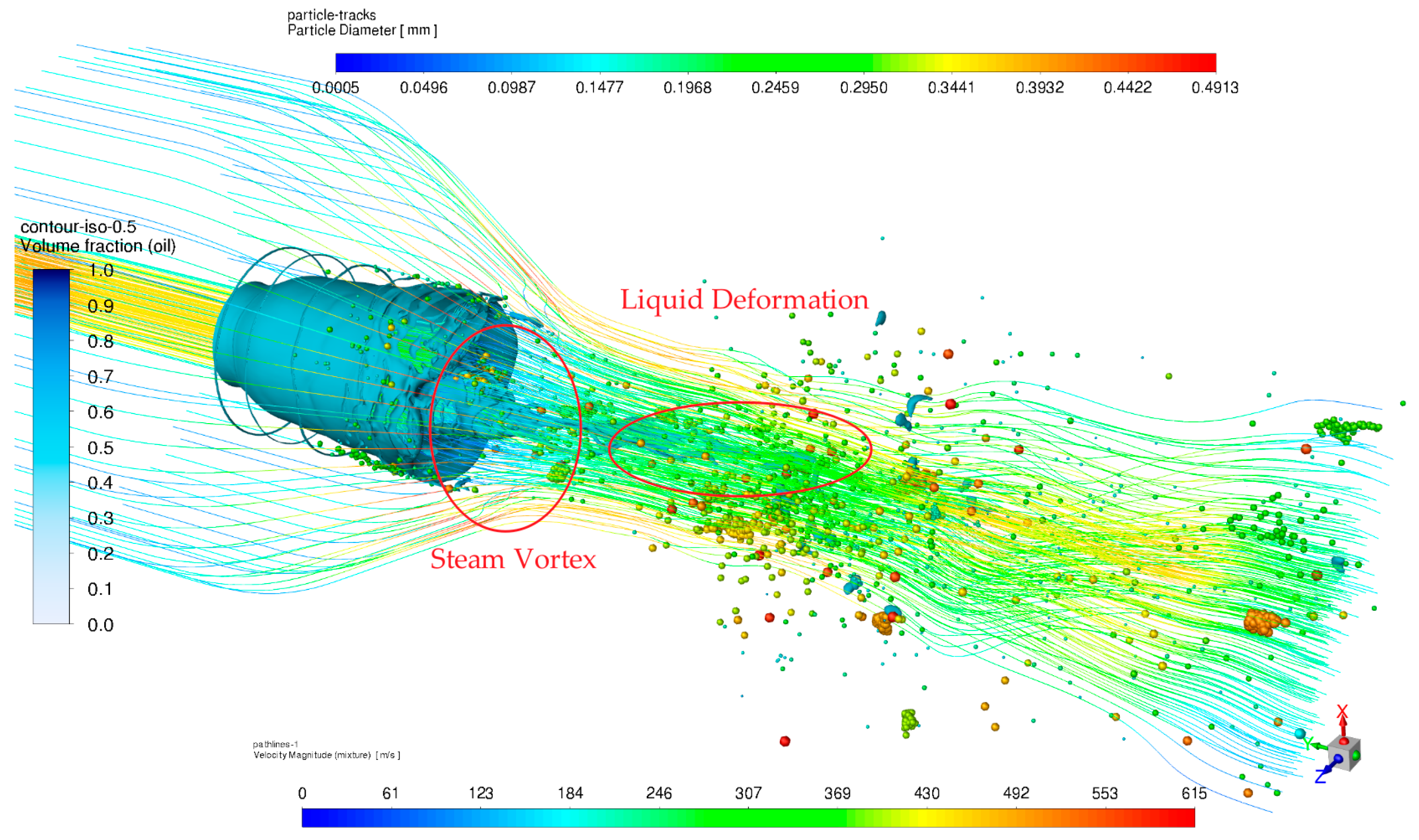
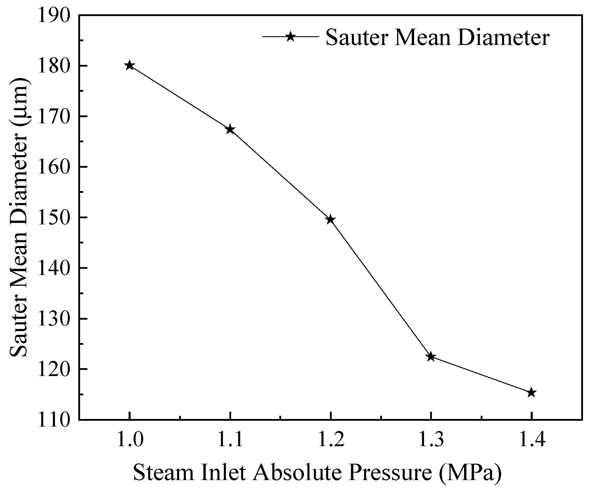
This paper studied the atomization performance of the two-stage supersonic steam atomizer for high-viscosity liquid: the primary and secondary breakup processes of adiponitrile waste liquid were simulated, visualized, and analyzed. VOF-DPM bi-directional coupling model is an efficient tool for studying the atomization process of high-viscosity liquids. It is suitable for simulating the primary and secondary breakup and visualizing the calculation results. Combined with AMR technology, the VOF-DPM can save considerable calculation costs and shorten the period of verifying the nozzle structure. The atomization simulation results show that the two-stage supersonic steam atomizer proposed in this paper is suitable for atomizing high-viscosity waste liquid. The SMD is lower than 180 μm, and the atomization quality and particle size distribution can meet the needs of efficient combustion.
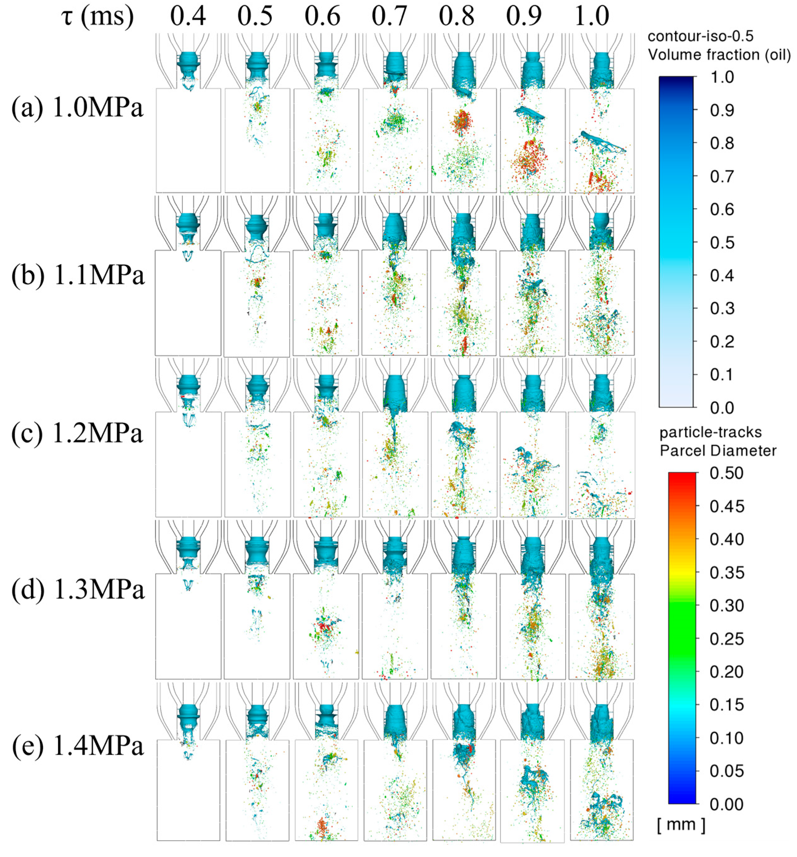
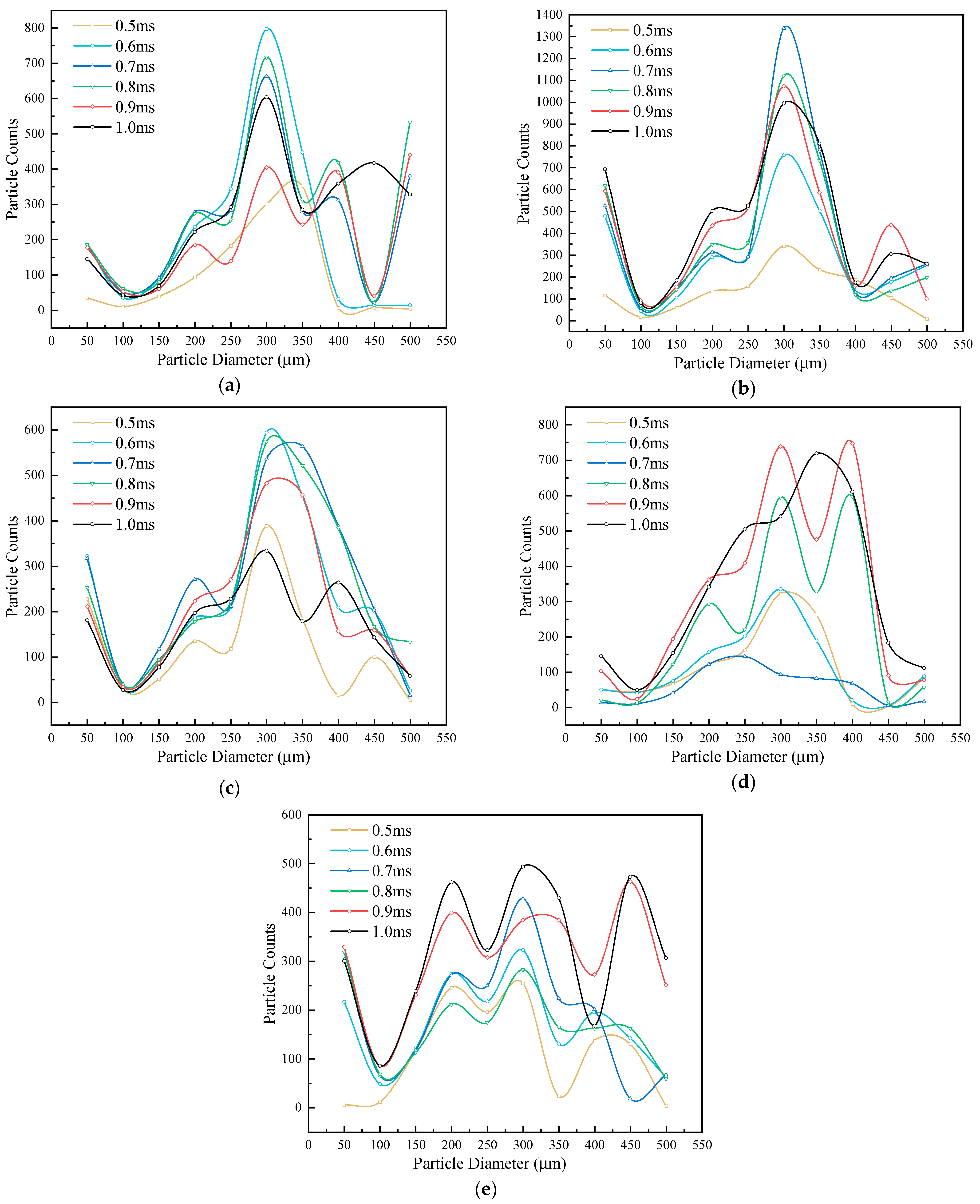
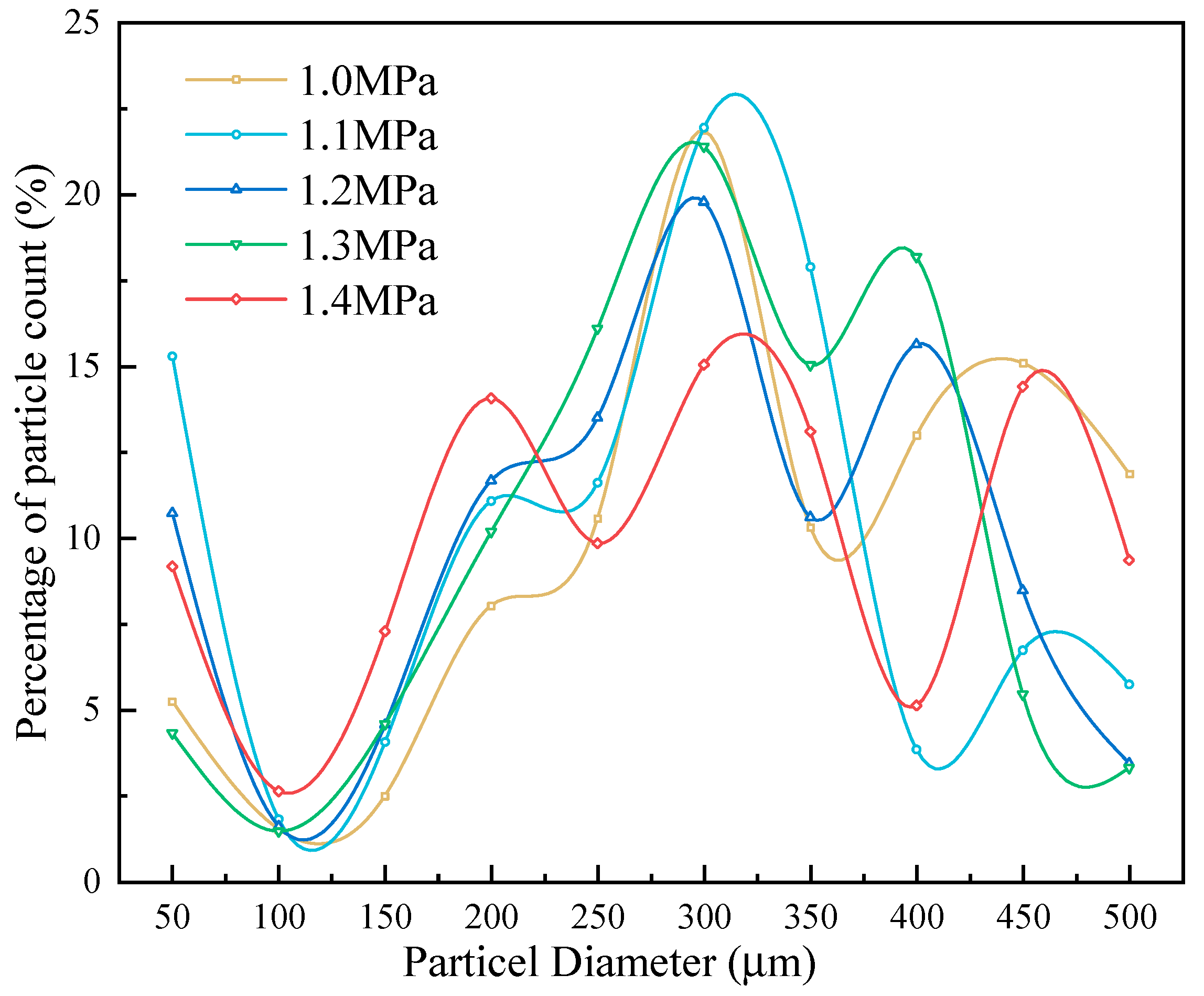
The absolute pressure of steam inlet significantly affects liquid fragmentation morphology, SMD, and particle size distribution. With the steam pressure increase, the liquid film’s main shape gradually changes from a large liquid circle to a short liquid filament. The number of liquid filaments near the liquid ring increases, and the liquid filament’s size gradually becomes smaller or even a liquid mass. The growth of the steam inlet absolute pressure also increases the steam speed. The steam wrapping the waste liquid will flow out of the nozzle earlier, so the stripped liquid film in the mixing chamber will meet with the second-stage steam in advance and produce smaller droplets. With a steam inlet absolute pressure increase, SMD becomes smaller, and the particle size distribution is more uniform. Still, at the same time, steam consumption is more, which will reduce the economy.
Due to the computational cost and robustness, the flow time in transient simulation is 1 ms. The study of extending the transient simulation flow time to the steady state has been underway further to reveal the atomization mechanism of high viscosity liquids.


