
Wireless Power Transfer in Electric Vehicles: A Review on Compensation Topologies, Coil Structures, and Safety Aspects

Abstract
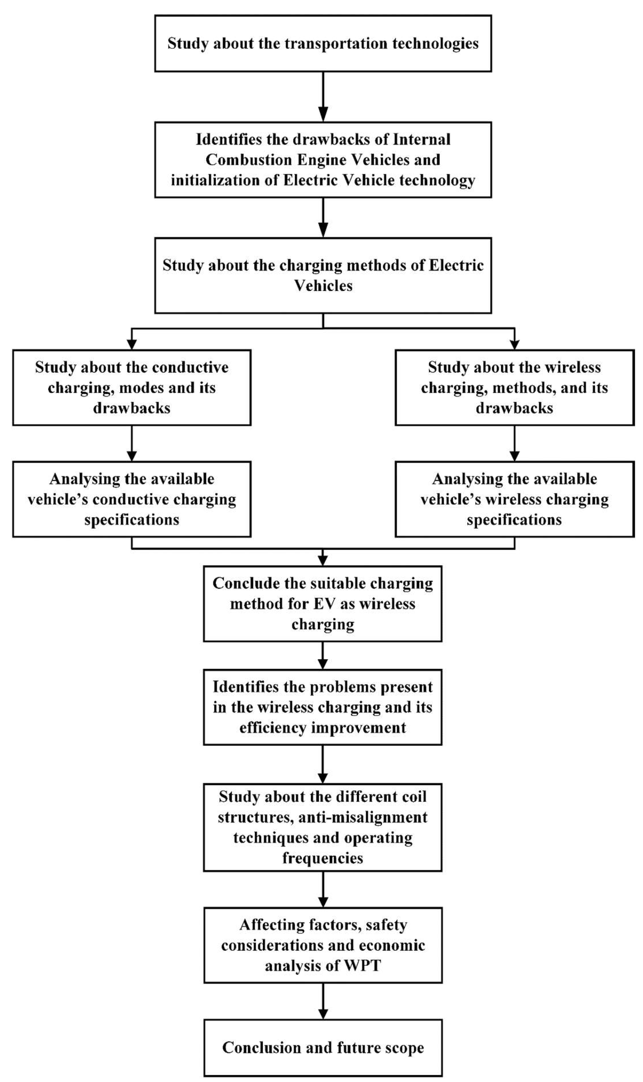
:1. Introduction
2. EV Charging Methods
2.1. Conductive Type, Plug-In Charging, or Wired Charging
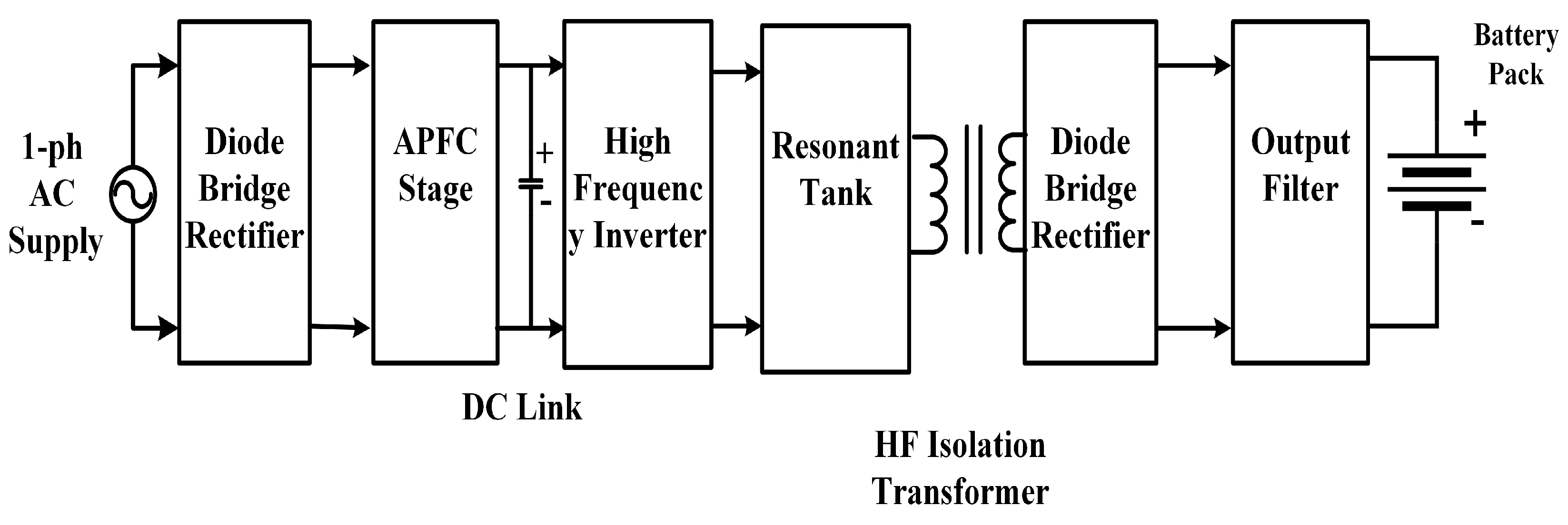
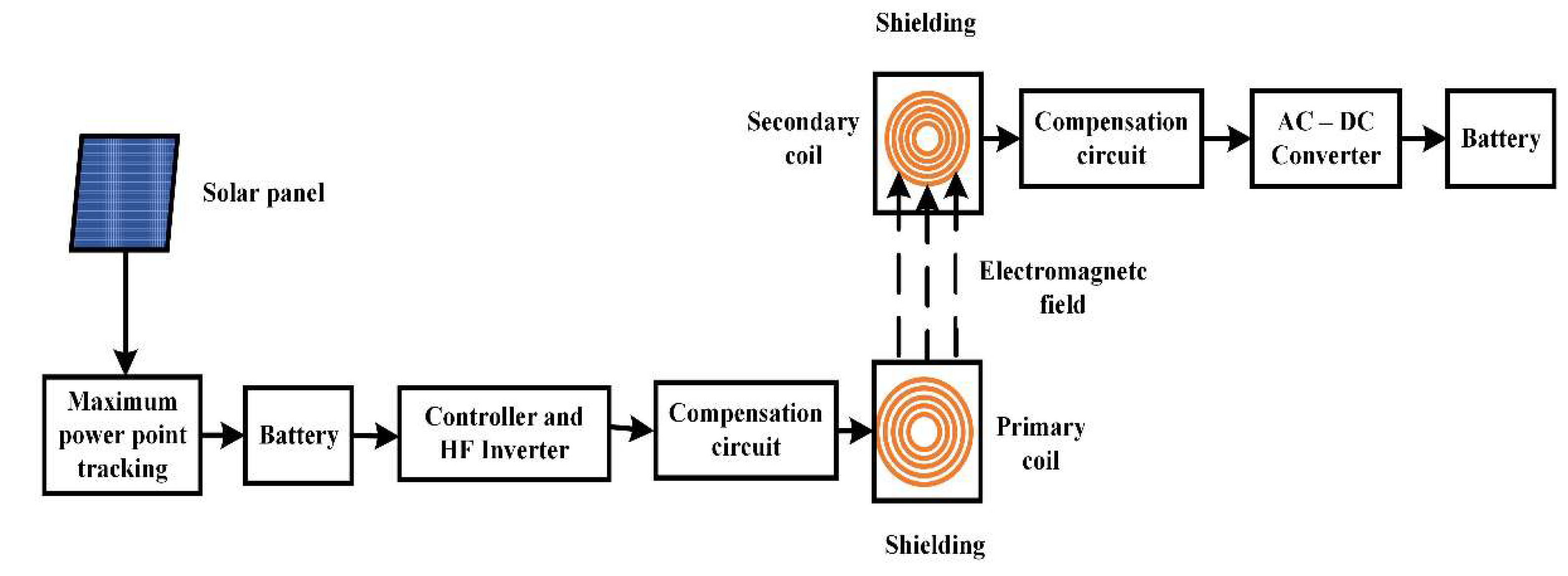
2.2. Wireless Charging System
3. Wireless Charging Technologies
3.1. Far-Field Charging
3.1.1. Microwave Power Transmission
3.1.2. Laser Power Transmission
3.2. Near-Field Charging
3.2.1. Capacitive Coupling Wireless Power Transfer
3.2.2. Coupled Magnetic Resonance Charging
3.2.3. Permanent Magnet Coupling Charging
3.2.4. Inductive Power Transfer
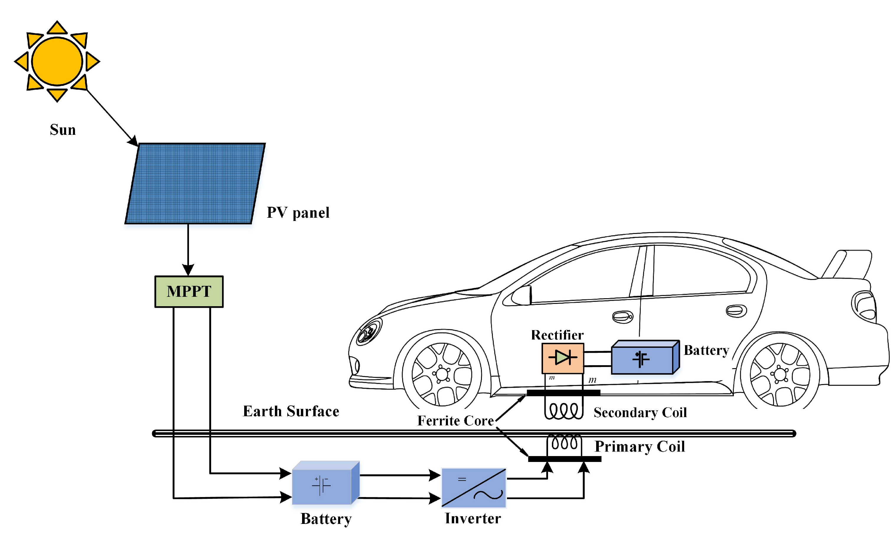
3.2.5. Static Charging
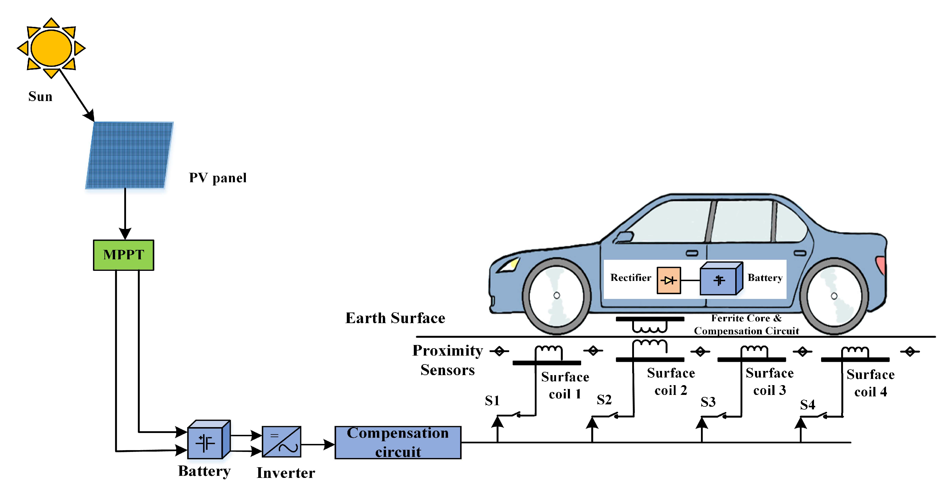
3.2.6. Dynamic Charging
4. Coil Structures
4.1. Polarized Pad Circular Coil
4.2. Polarized Rectangular Pad
4.3. Non-Polarized Pad Double-D Coil
4.4. Non-Polarized Pad Double-D Quadrature Coil
4.5. Non-Polarized Bi-Polar Double-D Coil
4.6. Tripolar Coil
4.7. Single-Layer Coils
4.7.1. U-Shape Coil
4.7.2. W-Shape Coil
4.7.3. I-Shape Coil
4.7.4. S-Shape Coil
4.7.5. N-Shape Coils
5. Operating Frequency
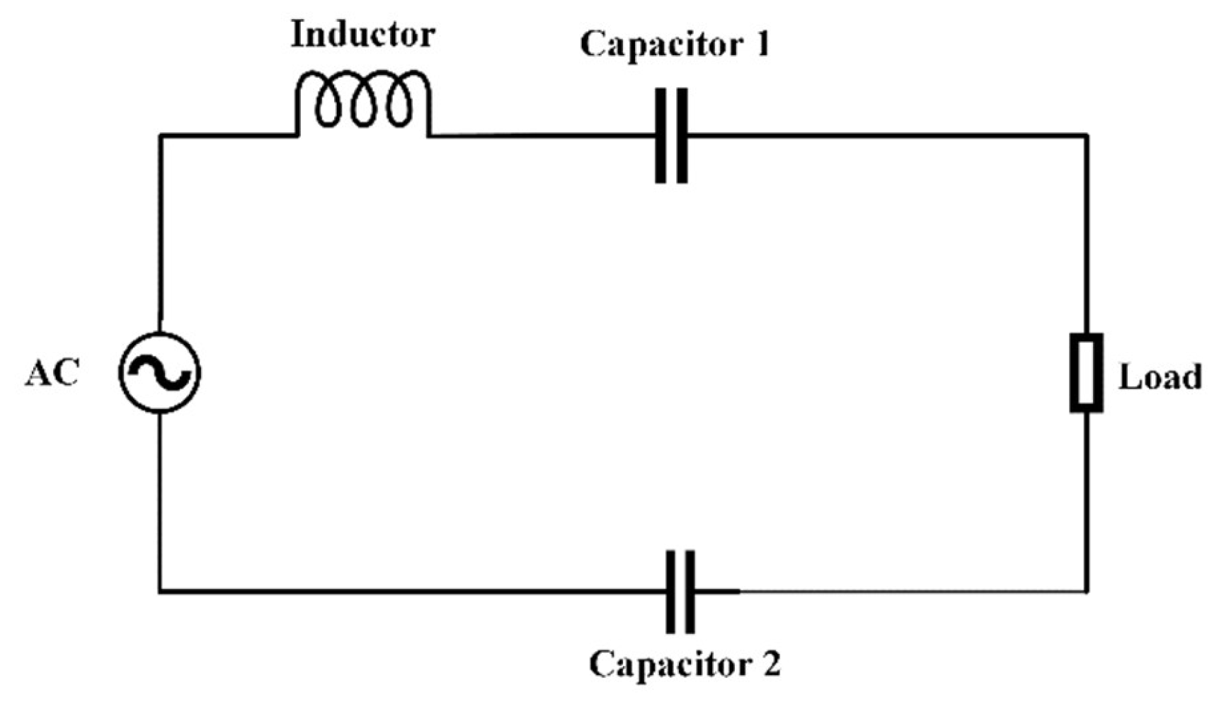
6. Compensation Topologies
- To generate reactive power at primary and secondary coils, which is required to generate a proper magnetic field. Additionally, primary coil compensation topologies are used to reduce the voltage and current ratings of input supply power, and secondary coil compensation topologies are used to improve the ability to transfer the power [216];
- To maintain the constant current and voltage [217];
- The coupling coefficient and quality factor can decide the maximum efficacy of the WPT system [218].
6.1. Basic Compensation Topology
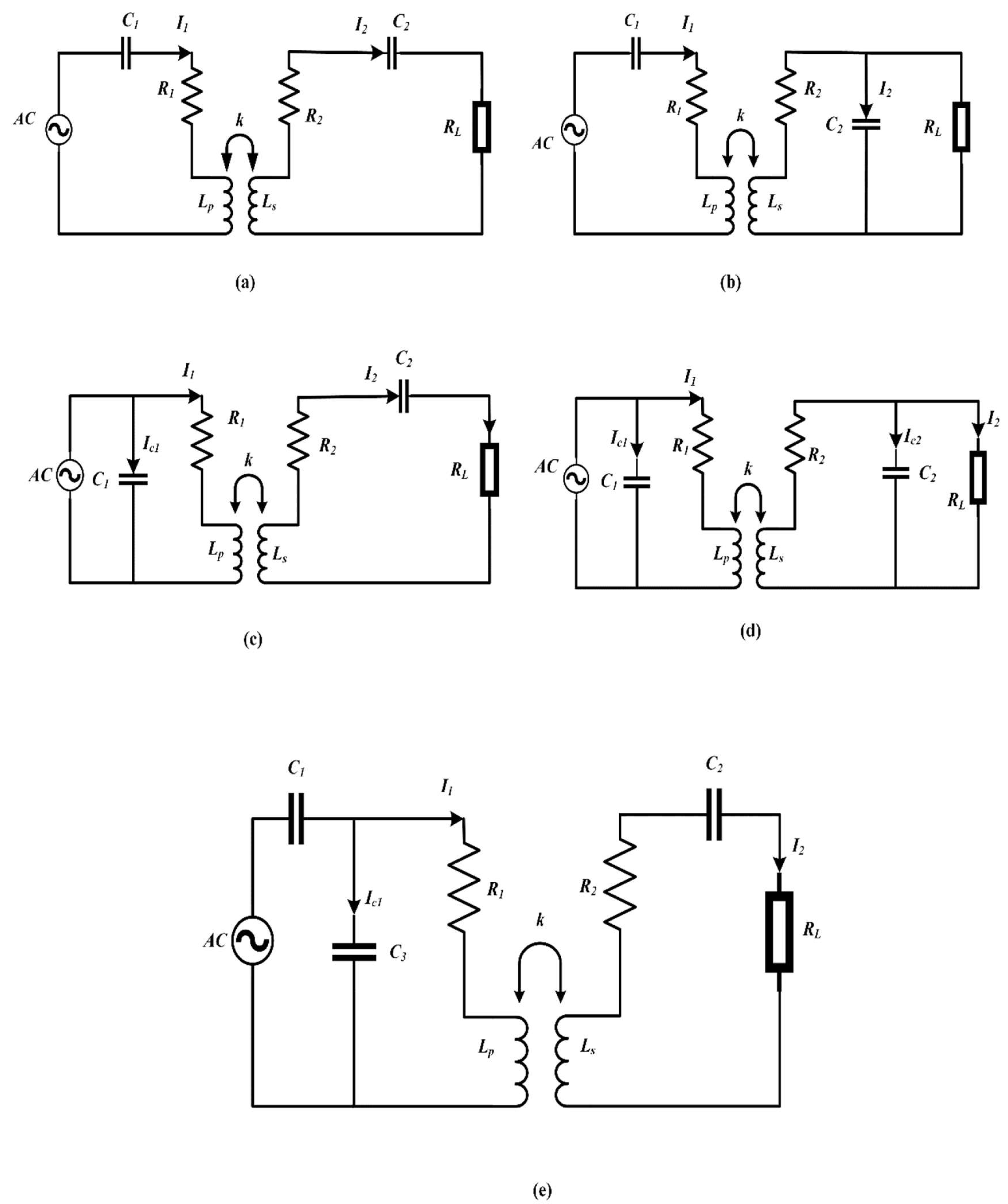
6.1.1. Series-Series Topology
6.1.2. Series-Parallel Topology
6.1.3. Parallel-Series Topology
6.1.4. Parallel-Parallel Topology
6.1.5. Series-Parallel-Series Topology
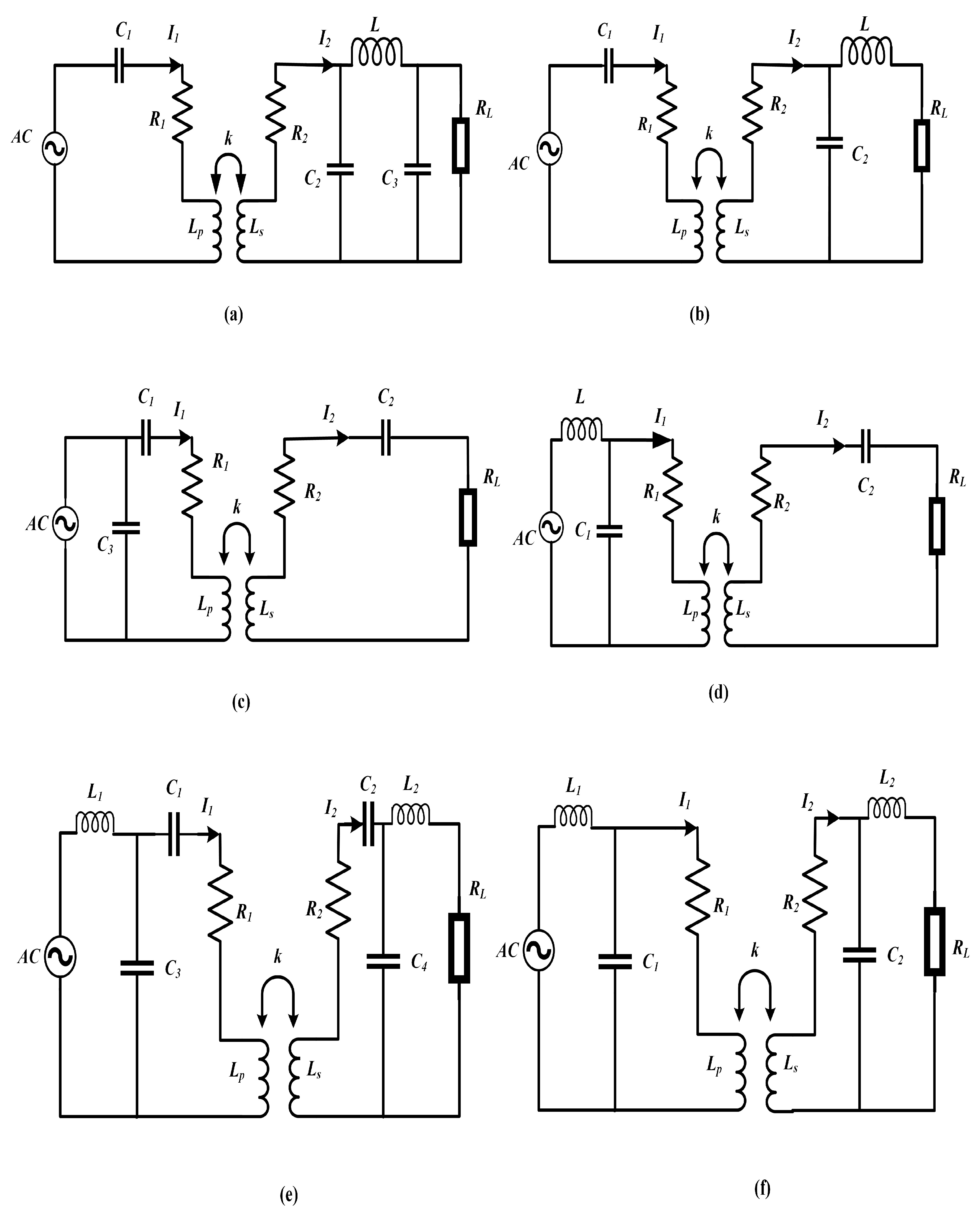
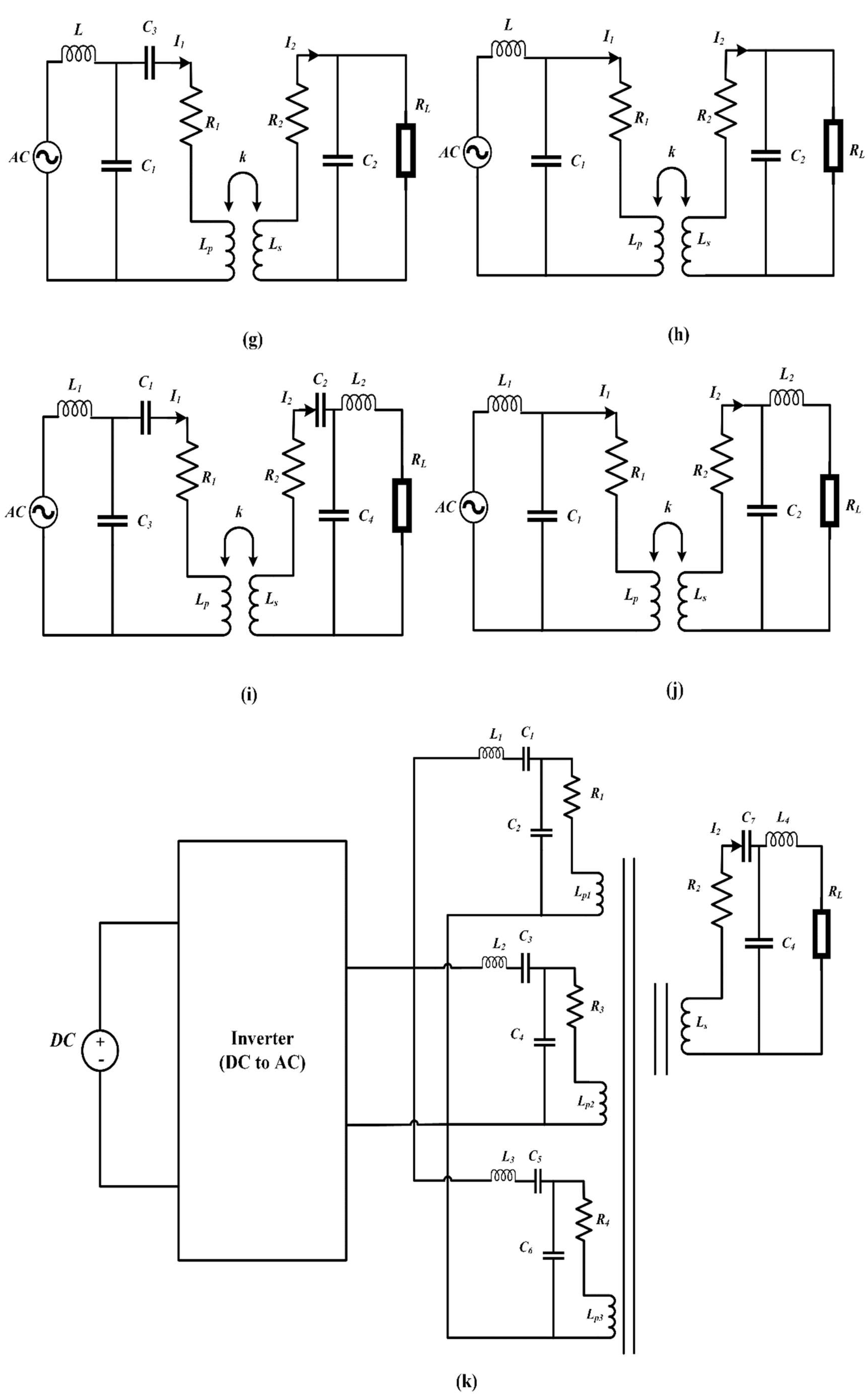
6.2. Hybrid Compensation Topologies

| Compensation Topologies | Coupling Coefficient (k) | Output Power, Voltage | Efficiency | N1, N2 | (mm) | (mm) | Airgap (mm) | Comments | |
|---|---|---|---|---|---|---|---|---|---|
| SS/LCC-LCC [239,240] | = 2, 3, 5 f = 85 | 0.135 | 1 kW, 50 V | 95% in SS, and 93% in LCC | 10, 8 | 500 | 400 | 200 | LCC-LCC compensation is more reliable for the electromagnetic field interface. |
| SS/LCC-LCC [241] | f = 85 | - | 7.7 kW 270–405 V | 96% in LCC | 800 | 600 | 200 | At lower values of mutual inductance, the LCC compensation has more efficiency. | |
| SS/LCL-LCL [243] | = 10 f = 85 | 0.1 | 3.3 kW | 93.1% in SS, 90% in LCC | 20 × 3, 17 × 2 layers | 550 × 400 mm2 | 240 × 240 mm2 | 100 | LCL-LCL compensation has a higher power factor value compared to SS. |
| LCC-LCC [244] | f = 79 R L = 10–200 | 0.18–0.32 | 7.5 kW 450 V | 96% | 1 | 800 | 600 | 200 | Resonant frequency (f) is not dependent on the load conditions or coupling coefficient. |
| LCC-LCC [245] | f = 95 | 0.14–0.30 | 5.6 kW 300–450 V | 95.36% | - | 600 | 600 | 150 | More induced couplings to increase the space between magnetic cores. |
| LCC-LCC [246] | f = 85 R L = 49.95 | 0.153 | 3.3 kW 405.7 V | 92.6% | 18, 16 | 600 | 300 | 150 | The battery has only a relationship with transmitter power and coupling coefficient, not with the compensation circuit. |
| LCC-LCC [247] | f = 85 | 0.1877 | 3 kW 300 V | 95.5% | - |
600 × 450 × 4 mm3 640 × 496 × 8 mm3 |
400 × 300 × 4 mm3 480 × 352 × 8 mm3 | 150 | A smaller level of transmitter and receiver design helps to neglect the extra-coupling effects. |
| Compensation Topologies | Resonant Frequency (kHz) | Coupling Coefficient (k) | Output Power, Voltage | Efficiency | Number of Turns and Dimensions of the Coils | Airgap (mm) | Comments |
|---|---|---|---|---|---|---|---|
| LCL-S LCC-S [248] | 140 | 0.18–0.32 | 1 kW, 90 V | LCC and LCL: 93% | Radius of the coil: 163 mm. | 100 | This compensation gives drastic transfer characteristics at different quality factor values. |
| Double-sided LCC [249] | 85 | 0.13 | 7.7 kW 270–405 V | 96% in LCC | Transmitter: 9 turns, 6 × (388 × 400 mm). Receiver: 9 turns, 485 × 400 mm. | 150 | This compensation topology is more suitable for reducing the power fluctuations of dynamic wireless charging. |
| LCL [250] | 85 | 0.037–0.054 | 5 kW | - | Transmitter and receiver: 350 mm × 700 mm. | 240 | By switching on the single primary coil, you can transfer the power throughout the track. |
| SS [251] | 79 | 0.4 | 20 kW | 80% | Transmitter: 9 turns, 10 cm × 75 cm. Receiver: 12 turns, 25 cm × 20 cm. | 100 | This system uses a new downscale prototype instead of a real-time model, operating at a frequency of 85 kHz. |
| SP [252] | 23 | - | 2 kW | 95.36% | Transmitter: 7 turns, 330 mm diameter. Receiver: 5 turns, 330 mm diameter. | 100 | There are different types of dynamic charging, like power variations due to positions and the decrement of the magnetic field below the safe limits with shielding effects. |
| SS [253,254] | 85 | - | - | 97.6% | Transmitter: 8 turns, width is 58 mm. Receiver: 8 turns, width is 38 mm. | 200 | Using the Surface Impedance Boundary Condition technique to study the induced losses and investigate the different lengths. |
7. Affecting Factors and Safety Considerations for WPT
8. Economic Analysis of Wireless Charging-Based Electric Vehicles
- A 50 EV parking area;
- 200 EV parking garage.
| Price per Pair of Charging Points [EUR] | ||
|---|---|---|
| Wireless | Wired | |
| Price of the charging system’s purchase | 7200 | 3800 |
| Initial cost of charging systems | 1200 | 500 |
| Additional price for maintenance/year | 22 | 92 |
| Price for maintenance/year | 30 | 40 |
8.1. Economic Facilities of Static Charging
8.2. Economic Facilities of Dynamic Charging
9. Conclusions and Future Scope
Author Contributions
Funding
Data Availability Statement
Acknowledgments
Conflicts of Interest
Abbreviations
| EV | Electric Vehicle |
| ICE | Internal Combustion Engine |
| DC | Direct Current |
| USA | United States of America |
| WPT | Wireless Power Transfer |
| V2G | Vehicle to Grid |
| G2V | Grid to Vehicle |
| AC | Alternating Current |
| ZVS | Zero Voltage Switching |
| ZCS | Zero Current Switching |
| LC | Inductor-Capacitor |
| EMI | Electromagnetic Interference |
| PHEV | Plug-in Hybrid Electric Vehicles |
| Hr | Hour |
| kWh | Kilowatt Hour |
| cm | Centimeter |
| Km | Kilometer |
| Euro | |
| Li-Ion | Lithium Ion |
| Sodium Nickel Chloride | |
| Ni-MH | Nickel Metal Hydride |
| Li-S | Lithium Sulfur |
| Kg | Kilogram |
| SOC | State of Charge |
| SOH | State of Health |
| CCWPT | Capacitive Coupling Wireless Power Transfer |
| CMR | Coupled Magnetic Resonance |
| IPT | Inductive Power Transfer |
| PMC | Permanent Magnet Coupled transfer |
| NASA | National Aeronautics and Space Administration |
| PCB | Printed Circuit Board |
| SHARP | Stationary High-Altitude Relay Platform |
| Input Voltage | |
| Output Voltage | |
| Load Resistance | |
| Capacitance | |
| MHz | Megahertz |
| GHz | Gigahertz |
| LED | Light Emitting Diode |
| RFID | Radio Frequency Identification |
| DWC | Dynamic Wireless Charging |
| TULIP | Transport Urban Libre Individual Public |
| ORNL | Oak Ridge National Laboratory |
| EMF | Electromotive Force |
| GPSSC | Grouped Periodic Series Spiral Coupler |
| KAIST | Korea Advanced Institute of Science and Technology |
| PTS | Parity-Time Symmetric |
| FEA | Finite Element Analysis |
| PPs | Polarized Pads |
| NPPs | Non-Polarized Pads |
| DD | Double-D Coil |
| DDQ | Non-Polarized pad Double-D coil |
| DDQP | Non-Polarized pad Double-D Quadrature coil |
| BP | Bi-Polar |
| Quality Factor | |
| Equivalent Resistance | |
| ω | Resonant Frequency |
| M | Mutual Inductance |
| SS | Series-Series |
| SP | Series-Parallel |
| PS | Parallel-Series |
| PP | Parallel-Parallel |
| SPS | Series-Parallel-Series |
| k | Coupling coefficient |
| Self-inductance of the primary coil | |
| Self-inductance of the secondary coil | |
| $ | Dollar |
| CAN | Controller Area Network |
| BMS | Battery Management System |
| SAE | Society of Automotive Engineers |
| IEC | International Electrotechnical Commission |
| ICES | International Committee on Electromagnetic Safety |
| IEEE | Institute of Electrical and Electronics Engineers |
| ICNIRP | International Commission on Non-Ionizing Radiation Protection |
| UL | Underwriter Laboratories |
References
- Dai, J.; Ludois, D.C. A Survey of Wireless Power Transfer and a Critical Comparison of Inductive and Capacitive Coupling for Small Gap Applications. IEEE Trans. Power Electron. 2015, 30, 6017–6029. [Google Scholar] [CrossRef]
- Pathipati, V.K. Design of a Novel Ferrite Core-based Highly Efficient Wireless Resonant Inductive Power Transfer System; University of Ontario Institute of Technology: Oshawa, ON, USA, 2016. [Google Scholar]
- Miller, J.M.; Onar, O.C.; Chinthavali, M. Primary-side power flow control of wireless power transfer for electric vehicle charging. IEEE J. Emerg. Sel. Top. Power Electron. 2015, 3, 147–162. [Google Scholar] [CrossRef]
- Qiu, C.; Chau, K.T.; Liu, C.; Chan, C.C. Overview of wireless power transfer for electric vehicle charging. In Proceedings of the 2013 World Electric Vehicle Symposium and Exhibition (EVS27), Barcelona, Spain, 17–20 November 2014; pp. 1–9. [Google Scholar]
- Sasaki, S.; Tanaka, K.; Maki, K.I. Microwave power transmission technologies for solar power satellites. Proc. IEEE 2013, 101, 1438–1447. [Google Scholar] [CrossRef]
- Choi, S.Y.; Gu, B.W.; Jeong, S.Y.; Rim, C.T. Advances in wireless power transfer systems for roadway-powered electric vehicles. IEEE J. Emerg. Sel. Top. Power Electron. 2015, 3, 18–36. [Google Scholar] [CrossRef]
- Mi, C.C.; Buja, G.; Choi, S.Y.; Rim, C.T. Modern Advances in Wireless Power Transfer Systems for Roadway Powered Electric Vehicles. IEEE Trans. Ind. Electron. 2016, 63, 6533–6545. [Google Scholar] [CrossRef]
- Ahmad, F.; Alam, M.S.; Asaad, M. Developments in xEVs charging infrastructure and energy management system for smart microgrids including xEVs. Sustain. Cities Soc. 2017, 35, 552–564. [Google Scholar] [CrossRef]
- Wang, H.; Fan, Y.; Chen, C.; Tao, T.; Qiao, Z. Novel estimation solution on lithium-ion battery state of charge with current-free detection algorithm. IET Circuits Devices Syst. 2019, 13, 245–249. [Google Scholar] [CrossRef]
- Tesla, N. Apparatus for Transmitting Electrical Energy. U.S. Patent 1,119,732, 12 December 1914. [Google Scholar]
- Chen, L.; Liu, S.; Zhou, Y.C.; Cui, T.J. An optimizable circuit structure for high-efficiency wireless power transfer. IEEE Trans. Ind. Electron. 2013, 60, 339–349. [Google Scholar] [CrossRef]
- Li, S.; Liu, Z.; Zhao, H.; Zhu, L.; Shuai, C.; Chen, Z. Wireless Power Transfer by Electric Field Resonance and Its Application in Dynamic Charging. IEEE Trans. Ind. Electron. 2016, 63, 6602–6612. [Google Scholar] [CrossRef]
- Esmaeili Jamakani, B.; Mosallanejad, A.; Afjei, E.; Lahooti Eshkevari, A. Investigation of triple quadrature pad for wireless power transfer system of electric vehicles. IET Electr. Syst. Transp. 2020, 11, 58–68. [Google Scholar] [CrossRef]
- Nguyen, H.N.T.; Zhang, C.; Mahmud, M.A. Optimal Coordination of G2V and V2G to Support Power Grids with High Penetration of Renewable Energy. IEEE Trans. Transp. Electrif. 2015, 1, 188–195. [Google Scholar] [CrossRef]
- Wireless Chargers Archives—Qi Wireless Charging. Available online: http://www.qiwireless.com/category/wirelesschargers/ (accessed on 29 August 2022).
- Barnard, J.M.; Ferreira, J.A.; Van Wyk, J.D. Sliding transformers for linear contactless power delivery. IEEE Trans. Ind. Electron. 1997, 44, 774–779. [Google Scholar] [CrossRef]
- Coloma, P.; Donini, A.; Migliozzi, P.; Lavina, L.S.; Terranova, F. A High Efficiency 3.3 kW Loosely-Coupled Wireless Power Transfer System without Magnetic Material. AIP Conf. Proc. 2011, 1382, 262–264. [Google Scholar]
- Dik, A.; Omer, S.; Boukhanouf, R. Electric Vehicles: V2G for Rapid, Safe, and Green EV Penetration. Energies 2022, 15, 803. [Google Scholar] [CrossRef]
- Jain, P.; Jain, T. Impacts of G2V and V2G power on electricity demand profile. In Proceedings of the 2014 IEEE International Electric Vehicle Conference (IEVC), Florence, Italy, 17–19 December 2014. [Google Scholar]
- Huang, X.; Qiang, H.; Huang, Z.; Sun, Y.; Li, J. The interaction research of smart grid and EV based wireless charging. In Proceedings of the IEEE Vehicle Power and Propulsion Conference, Gijón, Spain, 26–29 October 2013; pp. 354–358. [Google Scholar]
- Habib, S.; Kamran, M.; Rashid, U. Impact analysis of vehicle-to-grid technology and charging strategies of electric vehicles on distribution networks—A review. J. Power Sources 2015, 277, 205–214. [Google Scholar] [CrossRef]
- Cheng, A.J.; Tarroja, B.; Shaffer, B.; Samuelsen, S. Comparing the emissions benefits of centralized vs. decentralized electric vehicle smart charging approaches: A case study of the year 2030 California electric grid. J. Power Sources 2018, 401, 175–185. [Google Scholar] [CrossRef]
- Tan, K.M.; Ramachandaramurthy, V.K.; Yong, J.Y. Integration of electric vehicles in smart grid: A review on vehicle to grid technologies and optimization techniques. Renew. Sustain. Energy Rev. 2016, 53, 720–732. [Google Scholar] [CrossRef]
- Ahmad, A.; Khan, Z.A.; Saad Alam, M.; Khateeb, S. A Review of the Electric Vehicle Charging Techniques, Standards, Progression, and Evolution of EV Technologies in Germany. Smart Sci. 2018, 6, 36–53. [Google Scholar] [CrossRef]
- Gschwendtner, C.; Sinsel, S.R.; Stephan, A. Vehicle-to-X (V2X) implementation: An overview of predominate trial configurations and technical, social and regulatory challenges. Renew. Sustain. Energy Rev. 2021, 145, 110977. [Google Scholar] [CrossRef]
- Erdinc, O.; Tascikaraoglu, A.; Paterakis, N.G.; Dursun, I.; Sinim, M.C.; Catalao, J.P.S. Comprehensive Optimization Model for Sizing and Siting of DG Units, EV Charging Stations, and Energy Storage Systems. IEEE Trans. Smart Grid. 2018, 9, 3871–3882. [Google Scholar] [CrossRef]
- Li, T.; Zhang, J.; Zhang, Y.; Jiang, L.; Li, B.; Yan, D.; Ma, C. An optimal design and analysis of a hybrid power charging station for electric vehicles considering uncertainties. In Proceedings of the IECON 2018—44th Annual Conference of the IEEE Industrial Electronics Society, Washington, DC, USA, 21–23 October 2018; Volume 1, pp. 5147–5152. [Google Scholar]
- Fathabadi, H. Novel grid-connected solar/wind powered electric vehicle charging station with vehicle-to-grid technology. Energy 2017, 132, 1–11. [Google Scholar] [CrossRef]
- Sufyan, M.; Rahim, N.A.; Muhammad, M.A.; Tan, C.K.; Raihan, S.R.S.; Bakar, A.H.A. Charge coordination and battery lifecycle analysis of electric vehicles with V2G implementation. Electr. Power Syst. Res. 2020, 184, 106307. [Google Scholar] [CrossRef]
- Hui, S.Y.R.; Zhong, W.; Lee, C.K. A critical review of recent progress in mid-range wireless power transfer. IEEE Trans. Power Electron. 2013, 29, 4500–4511. [Google Scholar] [CrossRef] [Green Version]
- Machura, P.; Li, Q. A critical review on wireless charging for electric vehicles. Renew. Sustain. Energy Rev. 2019, 104, 209–234. [Google Scholar] [CrossRef] [Green Version]
- Manohar, B.S.P.S.; Gandham, V.V.S.K.; Dhal, P.K. An Overview of Wireless Power Transmission System and Analysis of Different Methods. Int. J. Res. Appl. Sci. Eng. Technol. 2022, 3, 1818–1827. [Google Scholar] [CrossRef]
- Aydin, E.; Aydemir, M.T.; Aksoz, A.; El Baghdadi, M.; Hegazy, O. Inductive Power Transfer for Electric Vehicle Charging Applications: A Comprehensive Review. Energies 2022, 15, 4962. [Google Scholar] [CrossRef]
- Will DC Fast Charging Harm Electric Car Batteries? Available online: https://www.cnet.com/roadshow/news/will-dc-fast-charging-harm-electric-car-batteries/ (accessed on 23 August 2022).
- EV DC—DC Fast Chargers. Available online: https://www.power-sonic.com/dc-fast-chargers/ (accessed on 31 January 2023).
- Lukic, S.; Pantic, Z. Cutting the Cord: Static and Dynamic Inductive Wireless Charging of Electric Vehicles. IEEE Electrif. Mag. 2013, 1, 57–64. [Google Scholar] [CrossRef]
- Ahmadian, A.; Mohammadi-Ivatloo, B.; Elkamel, A. A Review on Plug-in Electric Vehicles: Introduction, Current Status, and Load Modeling Techniques. J. Mod. Power Syst. Clean Energy 2020, 8, 412–425. [Google Scholar] [CrossRef]
- Yilmaz, M.; Krein, P.T. Review of battery charger topologies, charging power levels, and infrastructure for plug-in electric and hybrid vehicles. IEEE Trans. Power Electron. 2013, 28, 2151–2169. [Google Scholar] [CrossRef]
- Mude, K.N. Battery charging method for electric vehicles: From wired to on-road wireless charging, Chinese. J. Electr. Eng. 2018, 4, 1–15. [Google Scholar] [CrossRef]
- Khaligh, A.; Dusmez, S. Comprehensive topological analysis of conductive and inductive charging solutions for plug-in electric vehicles. IEEE Trans. Veh. Technol. 2012, 61, 3475–3489. [Google Scholar] [CrossRef]
- J1772: SAE Electric Vehicle and Plug-in Hybrid Electric Vehicle Conductive Charge Coupler—SAE International. Available online: http://standards.sae.org/j1772_201602/ (accessed on 23 August 2022).
- Veneri, O.; Ferraro, L.; Capasso, C.; Iannuzzi, D. Charging infrastructures for EV: Overview of technologies and issues. In Proceedings of the 2012 Electrical Systems for Aircraft, Railway and Ship Propulsion, Bologna, Italy, 16–18 November 2012. [Google Scholar]
- PluginCars.com. Porsche Panamera S. E-Hybrid Review. Available online: http://www.plugincars.com/porsche-panamera-s-e-hybrid (accessed on 21 September 2022).
- Audi A3 Sportback e-tron. Available online: https://www.audiusa.com/models/audi-a3-sportback-e-tron/ (accessed on 21 September 2022).
- Specs Cadillac ELR Forum. Available online: https://www.gm-volt.com/threads/review-2014-cadillac-elr.337369/ (accessed on 21 September 2022).
- Chevrolet Pressroom-United States—Spark EV. Available online: http://media.chevrolet.com/media/us/en/chevrolet/vehicles/spark-ev/2016.tab1.html (accessed on 26 September 2022).
- Ford C-MAX Energi SE Plug-in Hybrid Model Highlights Ford. Com. Available online: https://www.ford.com/cars/c-max/2017/models/c-max-energise/ (accessed on 22 September 2022).
- Mercedes S550 Plug-in Hybrid|PluginCars.Com. Available online: http://www.plugincars.com/mercedes-s550-plug-hybrid (accessed on 22 September 2022).
- Mercedes-Benz C350 Plug-in Hybrid—EVBox. Available online: https://evchargeplus.com/ev-specification/mercedes-benz-c350-plug-in-hybrid// (accessed on 26 September 2022).
- Smart Electric Drive|PluginCars.Com. Available online: http://www.plugincars.com/smart-ed (accessed on 26 September 2022).
- The Toyota Prius Plug-in Hybrid|PluginCars.Com. Available online: http://plugincars.com/toyota-prius-plugin-hybrid (accessed on 26 September 2022).
- Specifications i-MiEV MITSUBISHI MOTORS. Available online: http://www.mitsubishi-motors.com/en/showroom/i-miev/specifications/ (accessed on 26 September 2022).
- Nissan LEAF Will Include Fast Charge Capability and Emergency Charging Cable at Launch—Gas 2. Available online: https://www.zap-map.com/charge-points/nissan-leaf-2430kwh-charging-guide/ (accessed on 26 September 2022).
- Review and Pictures of Porsche Cayenne S E-Hybrid|PluginCars.Com. Available online: http://www.plugincars.com/porsche-cayenne-s-e-hybrid (accessed on 26 September 2022).
- Volkswagen e-Golf Specifications. Available online: http://www.neftinvw.com/blog/2017-volkswagen-e-golf-specifications/ (accessed on 26 September 2022).
- Specs Ford Focus Electric Forum, My Focus Electric. Available online: http://www.myfocuselectric.com/specs/ (accessed on 26 September 2022).
- Fiat 500e|PluginCars.Com. Available online: http://www.plugincars.com/fiat-500e (accessed on 26 September 2022).
- Kia Soul EV Specifications. Available online: http://www.kiamedia.com/us/en/models/soul-ev/2017/specifications (accessed on 26 September 2022).
- Honda Accord Plug-in Hybrid|PluginCars.Com. Available online: http://www.plugincars.com/honda-accord-plug-hybrid (accessed on 26 September 2022).
- BMW i3 (94 Ah) Release Date, Price and Specs—Roadshow. Available online: https://www.cnet.com/roadshow/auto/2017-bmw-i3/preview/ (accessed on 26 September 2022).
- Mercedes B—Class Electric (Pure EV). Available online: https://www.mercedes-benz.com/en/vehicles/passenger-cars/b-class/ (accessed on 26 September 2022).
- Tesla Model S (Pure EV). Available online: https://www.tesla.com/blog/new-tesla-model-s-now-quickest-production-car-world (accessed on 26 September 2022).
- Iclodean, C.; Varga, B.; Burnete, N.; Cimerdean, D.; Jurchiş, B. Comparison of Different Battery Types for Electric Vehicles. IOP Conf. Ser. Mater. Sci. Eng. 2017, 252, 012058. [Google Scholar] [CrossRef] [Green Version]
- EV Charging Standards and Specifications. Available online: https://electrek.co/2021/07/21/electric-vehicle-ev-charging-standards-and-how-they-differ/ (accessed on 17 October 2022).
- EV Dc Fast Charging Standards. Available online: https://greentransportation.info/ev-charging/range-confidence/chap8-tech/ev-dc-fast-charging-standards-chademo-ccs-sae-combo-tesla-supercharger-etc.html (accessed on 17 October 2022).
- Duan, C.; Jiang, C.; Taylor, A.; Bai, K.H. Design of a zero-voltage-switching large-air-gap wireless charger with low electric stress for electric vehicles. IET Power Electron. 2013, 6, 1742–1750. [Google Scholar] [CrossRef]
- Ahmad, A.; Alam, M.S.; Chaban, R.C. Efficiency enhancement of wireless charging for Electric vehicles through reduction of coil misalignment. In Proceedings of the 2017 IEEE Transportation Electrification Conference and Expo (ITEC), Chicago, IL, USA, 22–24 June 2017; pp. 21–26. [Google Scholar]
- Chen, W.; Liu, C.; Lee, C.H.T.; Shan, Z. Cost-effectiveness comparison of coupler designs of wireless power transfer for electric vehicle dynamic charging. Energies 2016, 9, 906. [Google Scholar] [CrossRef] [Green Version]
- Buja, G.; Chun-Taek, R.; Chunting, C. Mi, Dynamic charging for electric vehicles (EV) by wireless power transfer. IEEE Trans. Ind. Electron. 2016, 63, 6530–6532. [Google Scholar] [CrossRef] [Green Version]
- Bhattacharya, S.; Tan, Y.K. Design of static wireless charging coils for integration into electric vehicle. In Proceedings of the 2012 IEEE Third International Conference on Sustainable Energy Technologies (ICSET), Kathmandu, Nepal, 24–27 September 2012; pp. 146–151. [Google Scholar]
- Vukajlovic, N.; Milićevic, D.; Dumnic, B.; Popadic, B. Comparative analysis of the supercapacitor influence on lithium battery cycle life in electric vehicle energy storage. J. Energy Storage 2020, 31, 101603. [Google Scholar] [CrossRef]
- Li, Z.; Zhu, C.; Jiang, J.; Song, K.; Wei, G. A 3-kW Wireless Power Transfer System for Sightseeing Car Supercapacitor Charge. IEEE Trans. Power Electron. 2017, 32, 3301–3316. [Google Scholar] [CrossRef]
- Elahi, A.; Amin, A.A.; Shami, U.T.; Usman, M.T.; Iqbal, M.S. Efficient wireless charging system for supercapacitor-based electric vehicle using inductive coupling power transfer technique. Adv. Mech. Eng. 2019, 11, 1–10. [Google Scholar] [CrossRef]
- Wang, R.; Yao, M.; Niu, Z. Smart supercapacitors from materials to devices. InfoMat 2020, 2, 113–125. [Google Scholar] [CrossRef] [Green Version]
- Sudworth, J.L. The sodium/nickel chloride (ZEBRA) battery. J. Power Sources 2001, 100, 149–163. [Google Scholar] [CrossRef]
- Hawkins, T.R.; Singh, B.; Majeau-Bettez, G.; Strømman, A.H. Comparative Environmental Life Cycle Assessment of Conventional and Electric Vehicles. J. Ind. Ecol. 2013, 17, 53–64. [Google Scholar] [CrossRef]
- Nykvist, B.; Nilsson, M. Rapidly falling costs of battery packs for electric vehicles. Nat. Clim. Chang. 2015, 5, 329–332. [Google Scholar] [CrossRef]
- Chen, Z.; Guo, N.; Li, X.; Shen, J.; Xiao, R.; Li, S. Battery pack grouping and capacity improvement for electric vehicles based on a genetic algorithm. Energies 2017, 10, 439. [Google Scholar] [CrossRef] [Green Version]
- Gerssen-Gondelach, S.J.; Faaij, A.P.C. Performance of batteries for electric vehicles on short and longer term. J. Power Sources 2012, 212, 111–129. [Google Scholar] [CrossRef]
- Budde-Meiwes, H.; Drillkens, J.; Lunz, B.; Muennix, J.; Rothgang, S.; Kowal, J.; Sauer, D.U. A review of current automotive battery technology and future prospects. Proc. Inst. Mech. Eng. Part D J. Automob. Eng. 2013, 227, 761–776. [Google Scholar] [CrossRef]
- Doughty, D.; Roth, E.P. A General Discussion of Li Ion Battery Safety. Electrochem. Soc. Interface 2012, 21, 37–44. [Google Scholar]
- Ji, D.; Chen, L.; Ma, T.; Wang, J.; Liu, S.; Ma, X.; Wang, F. Research on adaptability of charging strategy for electric vehicle power battery. J. Power Sources 2019, 437, 1–9. [Google Scholar] [CrossRef]
- Salgado, R.M.; Danzi, F.; Oliveira, J.E.; El-Azab, A.; Camanho, P.P.; Braga, M.H. The Latest Trends in Electric Vehicles Batteries. Molecules 2021, 26, 3188. [Google Scholar] [CrossRef]
- Lu, L.; Han, X.; Li, J.; Hua, J.; Ouyang, M. A review on the key issues for lithium-ion battery management in electric vehicles. J. Power Sources 2013, 226, 272–288. [Google Scholar] [CrossRef]
- Zou, Y.; Hu, X.; Ma, H.; Li, S.E. Combined State of Charge and State of Health estimation over lithium-ion battery cell cycle lifespan for electric vehicles. J. Power Sources 2015, 273, 793–803. [Google Scholar] [CrossRef]
- Wang, K.; Wang, W.; Wang, L.; Li, L. An improved SOC control strategy for electric vehicle hybrid energy storage systems. Energies 2020, 13, 5297. [Google Scholar] [CrossRef]
- Wang, K.; Liu, C.; Sun, J.; Zhao, K.; Wang, L.; Song, L.; Duan, C.; Li, L. State of Charge Estimation of Composite Energy Storage Systems with Supercapacitors and Lithium Batteries. Complexity 2021, 2021, 8816250. [Google Scholar] [CrossRef]
- Thounthong, P.; Raël, S.; Davat, B. Energy management of fuel cell/battery/supercapacitor hybrid power source for vehicle applications. J. Power Sources 2009, 193, 376–385. [Google Scholar] [CrossRef]
- Omariba, Z.B.; Zhang, L.; Sun, D. Review of Battery Cell Balancing Methodologies for Optimizing Battery Pack Performance in Electric Vehicles. IEEE Access 2019, 7, 129335–129352. [Google Scholar] [CrossRef]
- Choi, S.; Huh, J.; Lee, W.Y.; Lee, S.W.; Rim, C.T. New cross-segmented power supply rails for roadway-powered electric vehicles. IEEE Trans. Power Electron. 2013, 28, 5832–5841. [Google Scholar] [CrossRef]
- Budhia, M.; Boys, J.T.; Covic, G.A.; Huang, C.Y. Development of a single-sided flux magnetic coupler for electric vehicle IPT charging systems. IEEE Trans. Ind. Electron. 2013, 60, 318–328. [Google Scholar] [CrossRef]
- Miller, J.M.; Jones, P.T.; Li, J.M.; Onar, O.C. ORNL experience and challenges facing dynamic wireless power charging of EV’s. IEEE Circuits Syst. Mag. 2015, 15, 40–53. [Google Scholar] [CrossRef]
- Ojika, S.; Miura, Y.; Ise, T. Evaluation of Inductive Contactless Power Transfer Outlet with Coaxial Coreless Transformer. Electr. Eng. Japan 2016, 195, 57–67. [Google Scholar] [CrossRef]
- Jiang, A.; Maglaras, F.V.; Moschoyiannis, S. Dynamic wireless charging of electric vehicles on the move with Mobile Energy Disseminators. Int. J. Adv. Comput. Sci. Appl. 2015, 6, 1–13. [Google Scholar]
- Mohamed, A.A.S.; Lashway, C.R.; Mohammed, O. Modeling and feasibility analysis of quasi-dynamic WPT system for EV applications. IEEE Trans. Transp. Electrif. 2017, 3, 343–353. [Google Scholar] [CrossRef]
- Garnica, J.; Chinga, R.A.; Lin, J. Wireless power transmission: From far field to near field. Proc. IEEE 2013, 101, 1321–1331. [Google Scholar] [CrossRef]
- Brown, W.C. The History of Power Transmission by Radio Waves. IEEE Trans. Microw. Theory Tech. 1984, 32, 1230–1242. [Google Scholar] [CrossRef] [Green Version]
- Hiroshi, M. Research on Solar Power Satellites and Microwave Power Transmission in Japan. Earth 2002, 3, 36–45. [Google Scholar]
- Brown, W.C. The history of wireless power transmission. Sol. Energy 1996, 56, 3–21. [Google Scholar] [CrossRef]
- Zhu, X.; Jin, K.; Hui, Q.; Gong, W.; Mao, D. Long-Range Wireless Microwave Power Transmission: A Review of Recent Progress. IEEE J. Emerg. Sel. Top. Power Electron. 2021, 9, 4932–4946. [Google Scholar] [CrossRef]
- Scharfman, W.E.; Taylor, W.C.; Morita, T. Breakdown Limitations on the Transmission of Microwave Power through the Atmosphere. IEEE Trans. Antennas Propag. 1964, 12, 709–717. [Google Scholar] [CrossRef]
- Jin, K.; Zhou, W. Wireless Laser Power Transmission: A Review of Recent Progress. IEEE Trans. Power Electron. 2019, 34, 3842–3859. [Google Scholar] [CrossRef]
- Mahmood, A.; Ismail, A.; Zaman, Z.; Fakhar, H.; Najam, Z.; Hasan, M.S.; Ahmed, S.H. A Comparative Study of Wireless Power Transmission Techniques. J. Basic Appl. Sci. Res. 2014, 4, 321–326. [Google Scholar]
- Kapranov, V.V.; Matsak, I.S.; Tugaenko, V.Y.; Blank, A.V.; Suhareva, N.A. Atmospheric turbulence effects on the performance of the laser wireless power transfer system, Free. Laser Commun. Atmos. Propag. 2017, 10096, 100961E. [Google Scholar]
- Umenei, A.E. Understanding Low Frequency Non-Raditive Power Transfer; Fulton Innovations White Papers; Fulton Innovation: Ada, MI, USA, 2011. [Google Scholar]
- Sazonov, E. Wearable Sensors, 2nd ed.; Elsevier: Amsterdam, The Netherlands, 2021. [Google Scholar]
- Sun, Z.; Xie, T.; Wang, X. Wireless Power Transfer for Medical Microsystems; Springer: New York, NY, USA, 2013. [Google Scholar]
- Chabalko, M.J.; Besnoff, J.; Ricketts, D.S. Magnetic Field Enhancement in Wireless Power with Metamaterials and Magnetic Resonant Couplers. IEEE Antennas Wirel. Propag. Lett 2016, 15, 452–455. [Google Scholar] [CrossRef]
- Agbinya, J.I. Wireless Power Transfer; River Publishers: Aalborg, Denmark, 2016. [Google Scholar]
- Huang, L.; Hu, A.P.; Swain, A.; Kim, S.; Ren, Y. An overview of capacitively coupled power transfer—A new contactless power transfer solution. In Proceedings of the 2013 IEEE 8th Conference on Industrial Electronics and Applications, Melbourne, VIC, Australia, 19–21 June 2013; pp. 461–465. [Google Scholar]
- Andreou, A.G. Capacitive Inter-Chip Data and Power Transfer for 3-D VLSI, IEEE Trans. Circuits Syst. II Express Briefs 2006, 53, 1348–1352. [Google Scholar]
- Sodagar, A.M.; Amiri, P. Capacitive coupling for power and data telemetry to implantable biomedical microsystems. In Proceedings of the 4th International IEEE/EMBS Conference on Neural Engineering, Antalya, Turkey, 29 April–2 May 2009; pp. 411–414. [Google Scholar]
- Jegadeesan, R.; Agarwal, K.; Guo, Y.X.; Yen, S.C.; Thakor, N.V. Wireless Power Delivery to Flexible Subcutaneous Implants Using Capacitive Coupling. IEEE Trans. Microw. Theory Tech. 2017, 65, 280–292. [Google Scholar] [CrossRef]
- Shmilovitz, D.; Abramovitz, A.; Reichman, I. Quasi-Resonant LED Driver with Capacitive Isolation and High PF. In Proceedings of the 2014 IEEE Applied Power Electronics Conference and Exposition-APEC 2014, Fort Worth, TX, USA, 16–20 March 2015; Volume 3, pp. 633–641. [Google Scholar]
- Wang, K.; Sanders, S. Contactless USB—A capacitive power and bidirectional data transfer system. In Proceedings of the 2014 IEEE Applied Power Electronics Conference and Exposition—APEC 2014, Fort Worth, TX, USA, 16–20 March 2014; pp. 1342–1347. [Google Scholar]
- Mostafa, T.M.; Muharam, A.; Hattori, R. Wireless battery charging system for drones via capacitive power transfer. In Proceedings of the 2017 IEEE PELS Workshop on Emerging Technologies: Wireless Power Transfer (WoW), Chongqing, China, 20–22 May 2017; pp. 1–6. [Google Scholar]
- Kurs, A.; Karalis, A.; Moffatt, R.; Joannopoulos, J.D.; Fisher, P.; Soljacic, M. Wireless power transfer via strongly coupled magnetic resonances. Science 2007, 317, 83–86. [Google Scholar] [CrossRef] [Green Version]
- World’s First Road-Powered Electric Vehicle Network Switches on in South Korea—ExtremeTech. Available online: https://www.extremetech.com/extreme/163171-worlds-first-road-powered-electric-vehicle-network-switches-on-in-south-korea (accessed on 12 August 2022).
- Shin, J.; Shin, S.; Kim, Y.; Ahn, S.; Lee, S.; Jung, G.; Jeon, S.J.; Cho, D.H. Design and implementation of shaped magnetic-resonance-based wireless power transfer system for roadway-powered moving electric vehicles. IEEE Trans. Ind. Electron. 2014, 61, 1179–1192. [Google Scholar] [CrossRef]
- Ahn, S.; Lee, J.Y.; Cho, D.H.; Kim, J. Magnetic field design for low emf and high efficiency wireless power transfer system in on-line electric vehicles. In Proceedings of the 21st CIRP Design Conference Korea 2011: Interdisciplinary Design, Daejeon, Republic of Korea, 30–31 March 2011; pp. 233–239. [Google Scholar]
- Imura, T.; Okabe, H.; Uchida, T.; Hori, Y. Study on open and short end helical antennas with capacitor in series of wireless power transfer using magnetic resonant couplings. In Proceedings of the 2009 35th Annual Conference of IEEE Industrial Electronics, Porto, Portugal, 3–5 November 2009; pp. 3848–3853. [Google Scholar]
- Mizuno, T.; Yachi, S.; Kamiya, A.; Yamamoto, D. Improvement in efficiency of wireless power transfer of magnetic resonant coupling using magnetoplated wire. IEEE Trans. Magn. 2011, 47, 4445–4448. [Google Scholar] [CrossRef] [Green Version]
- Li, W. High-Efficiency Wireless Power Transmission at Low Frequency Using Permanent Magnet Coupling; University of British Columbia: Vancouver, BC, Canada, 2009. [Google Scholar]
- Covic, G.A.; Boys, J.T.; Budhia, M.; Huang, C.Y. Electric vehicles-personal transportation for the future. World Electr. Veh. J. 2011, 4, 693–704. [Google Scholar] [CrossRef] [Green Version]
- Musavi, F.; Edington, M.; Eberle, W. Wireless power transfer: A survey of EV battery charging technologies. IEEE Energy Convers. Congr. Expo. ECCE 2012, 1804–1810. [Google Scholar]
- Bosshard, R.; Kolar, J.W. Multi-Objective Optimization of C/85 kHz IPT System for Public Transport. IEEE J. Emerg. Sel. Top. Power Electron. 2016, 4, 1370–1382. [Google Scholar] [CrossRef]
- Budhia, M.; Covic, G.; Boys, J. A new IPT magnetic coupler for electric vehicle charging systems. In Proceedings of the IECON 2010—36th Annual Conference on IEEE Industrial Electronics Society, Glendale, AZ, USA, 7–10 November 2010; pp. 2487–2492. [Google Scholar]
- Nagendra, G.R.; Covic, G.A.; Boys, J.T. Determining the physical size of inductive couplers for IPT EV systems. IEEE J. Emerg. Sel. Top. Power Electron. 2014, 3, 571–583. [Google Scholar] [CrossRef]
- Dashora, H.K.; Bertoluzzo, M.; Buja, G. Reflexive properties for different pick-up circuit topologies in a distributed IPT track. In Proceedings of the 2015 IEEE 13th International Conference on Industrial Informatics (INDIN), Cambridge, UK, 22–24 July 2015; pp. 69–75. [Google Scholar]
- Kazmierkowski, M.P.; Moradewicz, A.J. Unplugged but connected: Review of contactless energy transfer systems. IEEE Ind. Electron. Mag. 2012, 6, 47–55. [Google Scholar] [CrossRef]
- Oersted, H.C. Experiments on the effect of a current of electricity on the magnetic needle. Matrix Tensor Q. 1981, 32, 60–62. [Google Scholar]
- Maxwell, J.C. Summary for policymakers. Treatise Electr. Magn. 1954, 53, 1–30. [Google Scholar]
- Ampere’s Law—Reference Notes. Available online: http://notes.tyrocity.com/amperes-law/ (accessed on 18 August 2022).
- Lopez-Ramos, A.; Menendez, J.R.; Pique, C. Conditions for the validity of Faraday’s law of induction and their experimental confirmation. Eur. J. Phys. 2008, 29, 1069–1076. [Google Scholar] [CrossRef] [Green Version]
- Justin. A. Biot–Savart law. Int. J. Res. 2015, 2, 2348–6848. [Google Scholar]
- Maxwell, J.C. A dynamical theory of the electromagnetic field. R. Soc. 2012, 2, 32. [Google Scholar]
- Lu, X.; Wang, P.; Niyato, D.; Kim, D.I.; Han, Z. Wireless Charging Technologies: Fundamentals, Standards, and Network Applications. IEEE Commun. Surv. Tutor. 2016, 18, 1413–1452. [Google Scholar] [CrossRef] [Green Version]
- Otto, D. Induction Driven Vehicle: Pick-Up Coil Construction. New. Zealand Patent 167422, 14 August 1974. [Google Scholar]
- Bolger, J.G.; Ng, L.S.; Turner, D.B.; Wallace, R.I. Testing a Prototype Inductive Power Coupling for an Electric Highway System. In Proceedings of the 29th IEEE Vehicular Technology Conference, Arlington Heights, IL, USA, 27–30 March 1979; IEEE: New York, NY, USA; pp. 48–56. [Google Scholar]
- Zell, C.E.; Bolger, J.G. Development of an engineering prototype of a roadway powered electric transit vehicle system: A public/private sector program. IEEE Veh. Technol. Conf. 1982, 435–438. [Google Scholar]
- Systems Control Technology, Inc. Roadway Powered Electric Vehicle Project Track Construction and Testing Program Phase 3D; University of California, Berkeley: Berkeley, CA, USA, 1994. [Google Scholar]
- Shinohara. N. Wireless power transmission progress for electric vehicle in Japan. In Proceedings of the 2013 IEEE Radio and Wireless Symposium, Austin, TX, USA, 20–23 August 2013; pp. 109–111.
- Sakamoto, H.; Harada, K.; Washimiya, S.; Takehara, K.; Matsuo, Y.; Nakao, F. Large air-gap coupler for inductive charger. IEEE Trans. Magn. 1999, 35, 3526–3528. [Google Scholar] [CrossRef]
- Nikitin, P.; Rao, K.V.S.; Lazar, S. An overview of near field UHF RFID. In Proceedings of the 2007 IEEE International Conference on RFID, Grapevine, TX, USA, 26–28 March 2007; pp. 167–174. [Google Scholar]
- Wireless Power Trasfer—Electrical Engineering Stack Exchange. Power Supply—Is There Any Difference Between Induction and Resonant Wireless Energy Transfer—Electrical Engineering Stack Exchange. Available online: https://electronics.stackexchange.com/questions/25176/isthere-any-difference-betweeninduction-and-resonant-wireless-energy-trans (accessed on 8 August 2022).
- Khan, S.; Ahmad, A.; Ahmad, F.; Shafaati Shemami, M.; Saad Alam, M.; Khateeb, S. A Comprehensive Review on Solar Powered Electric Vehicle Charging System. Smart Sci. 2018, 6, 54–79. [Google Scholar] [CrossRef]
- Liang, J.; Wu, D.; Yu, J. A design method of compensation circuit for high-power dynamic capacitive power transfer system considering coupler voltage distribution for railway applications. Electron 2021, 10, 153. [Google Scholar] [CrossRef]
- From Wireless to Dynamic Electric Vehicle Charging: The Evolution of Qualcomm Halo. Available online: https://www.qualcomm.com/news/onq/2017/05/wireless-dynamic-ev-charging-evolution-qualcomm-halo (accessed on 31 January 2023).
- Mao, X.; Chen, J.; Zhang, Y.; Dong, J. A Simple and Reconfigurable Wireless Power Transfer System with Constant Voltage and Constant Current Charging. IEEE Trans. Power Electron. 2022, 37, 4921–4925. [Google Scholar] [CrossRef]
- Kumar, R.; Bharj, R.S.; Bharj, J.; Singh, G.N.; Sharma, M. Solar-Based Electric Vehicle Charging Stations in India: A Perspective. New Res. Dir. Sol. Energy Technol. 2021, 275–304. [Google Scholar]
- Zhang, X.; Yuan, Z.; Yang, Q.; Li, Y.; Zhu, J.; Li, Y. Coil Design and Efficiency Analysis for Dynamic Wireless Charging System for Electric Vehicles. IEEE Trans. Magn. 2016, 52, 8700404. [Google Scholar] [CrossRef]
- Jang, Y.J.; Jeong, S.; Lee, M.S. Initial energy logistics cost analysis for stationary, quasi-dynamic, & dynamic wireless charging public transportation systems. Energies 2016, 9, 483. [Google Scholar]
- Zhang, Z.; Chau, K.T. Homogeneous Wireless Power Transfer for Move-and-Charge. IEEE Trans. Power Electron. 2015, 30, 6213–6220. [Google Scholar] [CrossRef]
- Ko, Y.D.; Jang, Y.J. The optimal system design of the online electric vehicle utilizing wireless power transmission technology. IEEE Trans. Intell. Transp. Syst. 2013, 14, 1255–1265. [Google Scholar] [CrossRef]
- Choi, S.Y.; Huh, J.; Lee, W.Y.; Rim, C.T. Asymmetric coil sets for wireless stationary EV chargers with large lateral tolerance by dominant field analysis. IEEE Trans. Power Electron. 2014, 29, 6406–6420. [Google Scholar] [CrossRef]
- Choi, S.Y.; Jeong, S.Y.; Gu, B.W.; Lim, G.C.; Rim, C.T. Ultraslim S-Type Power Supply Rails for Roadway-Powered Electric Vehicles. IEEE Trans. Power Electron. 2015, 30, 6456–6468. [Google Scholar] [CrossRef]
- ORNL Surges Forward with 20-Kilowatt Wireless Charging for Vehicles ORNL. Available online: https://www.ornl.gov/news/ornl-surges-forward-20-kilowatt-wireless-charging-vehicles (accessed on 12 August 2022).
- Kim, J.H.; Lee, B.S.; Lee, J.H.; Lee, S.H.; Park, C.B.; Jung, S.M.; Lee, S.G.; Yi, K.P.; Baek, J. Development of 1-MW Inductive Power Transfer System for a High-Speed Train. IEEE Trans. Ind. Electron. 2015, 62, 6242–6250. [Google Scholar] [CrossRef]
- Wu, H.H.; Masquelier, M.P. An overview of a 50-kW inductive charging system for electric buses. In Proceedings of the 2015 IEEE Transportation Electrification Conference and Expo (ITEC), Dearborn, MI, USA, 14–17 June 2015; pp. 1–4. [Google Scholar]
- Taylor., M.F.; Blair Farley, K.; Gao, Y.; Bai, H.; Tse, Z.T.H. Electric vehicle wireless charging technology: A state-of-the-art review of magnetic coupling systems. Wirel. Power Transf. 2014, 1, 87–96. [Google Scholar]
- Tritschler, J.; Reichert, S.; Goeldi, B. A practical investigation of a high power, bidirectional charging system for electric vehicles. In Proceedings of the 2014 16th European Conference on Power Electronics and Applications, Lappeenranta, Finland, 26–28 August 2014. [Google Scholar]
- Li, W.; Zhao, H.; Li, S.; Deng, J.; Kan, T.; Mi, C.C. Integrated LCC Compensation Topology for Wireless Charger in Electric and Plug-in Electric Vehicles. IEEE Trans. Ind. Electron. 2015, 62, 4215–4225. [Google Scholar] [CrossRef]
- Nguyen, T.D.; Li, S.; Li, W.; Mi, C.C. Feasibility study on bipolar pads for efficient wireless power chargers. In Proceedings of the 2014 IEEE Applied Power Electronics Conference and Exposition—APEC 2014, Fort Worth, TX, USA, 16–20 March 2014; pp. 1676–1682. [Google Scholar]
- Lu, F.; Zhang, H.; Hofmann, H.; Mi, C. A high efficiency 3.3 kW loosely-coupled wireless power transfer system without magnetic material. In Proceedings of the 2015 IEEE Energy Conversion Congress and Exposition (ECCE), Montreal, QC, Canada, 20–24 September 2015; pp. 2282–2286. [Google Scholar]
- Bojarski, M.; Asa, E.; Colak, K.; Czarkowski, D. A 25-kW industrial prototype wireless electric vehicle charger. In Proceedings of the 2016 IEEE Applied Power Electronics Conference and Exposition (APEC), Long Beach, CA, USA, 20–24 March 2016; pp. 1756–1761. [Google Scholar]
- Bojarski, M.; Asa, E.; Colak, K.; Czarkowski, D. Analysis and control of multiphase inductively coupled resonant converter for wireless electric vehicle charger applications. IEEE Trans. Transp. Electrif. 2017, 3, 312–320. [Google Scholar] [CrossRef]
- Bosshard, R.; Kolar, J.W. Inductive Power Transfer for Electric Vehicle Charging: Technical challenges and tradeoffs. IEEE Power Electron. Mag. 2016, 3, 22–30. [Google Scholar] [CrossRef]
- Li, S.; Mi, C.C. Wireless power transfer for electric vehicle applications. IEEE J. Emerg. Sel. Top. Power Electron. 2015, 3, 4–17. [Google Scholar]
- Charging Electric Buses Quickly and Efficiently: Bus Stops Fitted with Modular Components Make ’Charge &Amp; Go’ Simple to Implement. Available online: http://www.conductix.us/en/news/2013-05-29/charging-electric-buses-quickly-and-efficiently-bus-stops-fitted-modular-components-make-charge-go (accessed on 12 August 2022).
- Wu, H.H.; Gilchrist, A.; Sealy, K.D.; Bronson, D. A high efficiency 5 kW inductive charger for EVs using dual side control. IEEE Trans. Ind. Inform. 2012, 8, 585–595. [Google Scholar] [CrossRef] [Green Version]
- Sato, F.; Morita, J.; Takura, T.; Sato, T.; Matsuki, H. Research on Highly Efficient Contactless Power Station System using Meander Coil for Moving Electric Vehicle Model. J. Magn. Soc. Japan 2012, 36, 249–252. [Google Scholar] [CrossRef] [Green Version]
- Chigira, M.; Nagatsuka, Y.; Kaneko, Y.; Abe, S.; Yasuda, T.; Suzuki, A. Small-size light-weight transformer with new core structure for contactless electric vehicle power transfer system. In Proceedings of the 2011 IEEE Energy Conversion Congress and Exposition, Phoenix, AZ, USA, 17–22 September 2011; pp. 260–266. [Google Scholar]
- Budhia, M.; Covic, G.A.; Boys, J.T. Design and optimization of circular magnetic structures for lumped inductive power transfer systems. IEEE Trans. Power Electron. 2011, 26, 3096–3108. [Google Scholar] [CrossRef]
- Kamineni, A.; Covic, G.A.; Boys, J.T. Analysis of Coplanar Intermediate Coil Structures in Inductive Power Transfer Systems. IEEE Trans. Power Electron. 2015, 30, 6141–6154. [Google Scholar] [CrossRef]
- Bosshard, R.; Kolar, J.W.; Mühlethaler, J.; Stevanovic, I.; Wunsch, B.; Canales, F. Modeling and η-α-pareto optimization of inductive power transfer coils for electric vehicles. IEEE J. Emerg. Sel. Top. Power Electron. 2015, 3, 50–64. [Google Scholar] [CrossRef]
- Horiuchi, T.; Kawashima, K. Study on Planar Antennas for Wireless Power Transmission of Electric Vehicles. IEEJ Trans. Ind. Appl. 2010, 130, 1371–1377. [Google Scholar] [CrossRef]
- Van Schuylenbergh, K.; Puers, R. Inductive Powering: Basic Theory and Application to Biomedical Systems, 1st ed.; Springer: Dordrecht, The Netherlands, 2014. [Google Scholar]
- Zhang, W.; Wong, S.C.; Tse, C.K.; Chen, Q. Analysis and comparison of secondary series-and parallel-compensated inductive power transfer systems operating for optimal efficiency and load-independent voltage-transfer ratio. IEEE Trans. Power Electron. 2014, 29, 2979–2990. [Google Scholar] [CrossRef]
- Pinuela, M.; Yates, D.C.; Lucyszyn, S.; Mitcheson, P.D. Maximizing DC-to-load efficiency for inductive power transfer. IEEE Trans. Power Electron. 2013, 28, 2437–2447. [Google Scholar] [CrossRef] [Green Version]
- Assawaworrarit, S.; Yu, X.; Fan, S. Robust wireless power transfer using a nonlinear parity-time-symmetric circuit. Nature 2017, 546, 387–390. [Google Scholar] [CrossRef] [PubMed]
- Dong, Z.; Li, Z.; Yang, F.; Qiu, C.W.; Ho, J.S. Sensitive readout of implantable microsensors using a wireless system locked to an exceptional point. Nat. Electron. 2019, 2, 335–342. [Google Scholar] [CrossRef]
- Schindler, J.; Li, A.; Zheng, M.C.; Ellis, F.M.; Kottos, T. Experimental study of active LRC circuits with PT symmetries. Phys. Rev. A-At. Mol. Opt. Phys. 2011, 84, 1–5. [Google Scholar] [CrossRef] [Green Version]
- Zhou, J.; Zhang, B.; Xiao, W.; Qiu, D.; Chen, Y. Nonlinear Parity-Time-Symmetric Model for Constant Efficiency Wireless Power Transfer: Application to a Drone-in-Flight Wireless Charging Platform. IEEE Trans. Ind. Electron. 2019, 66, 4097–4107. [Google Scholar] [CrossRef]
- Li, Y.; Hu, J.; Chen, F.; Li, Z.; He, Z.; Mai, R. Dual-phase-shift control scheme with current-stress and efficiency optimization for wireless power transfer systems. IEEE Trans. Circuits Syst. I Regul. Pap. 2018, 65, 3110–3121. [Google Scholar] [CrossRef]
- Qiao, K.; Sun, P.; Rong, E.; Sun, J.; Zhou, H.; Wu, X. Anti-misalignment and lightweight magnetic coupler with H-shaped receiver structure for AUV wireless power transfer. IET Power Electron. 2022, 15, 1843–1857. [Google Scholar] [CrossRef]
- Liu, H.; Li, Z.; Tian, Y.; Liu, Y.; Song, W. Anti-misalignment capability optimization for laminated magnetic couplers in wireless charging systems using balanced particle swarm optimization method. J. Power Electron. 2022, 23, 345–354. [Google Scholar] [CrossRef]
- Wu, M.; Yang, X.; Chen, W.; Wang, L.; Jiang, Y.; Gao, Q.; Yu, X. A Compact Coupler with Integrated Multiple Decoupled Coils for Wireless Power Transfer System and Its Anti-misalignment Control. IEEE Trans. Power Electron. 2022, 37, 12814–12827. [Google Scholar] [CrossRef]
- Li, J.; Yin, F.; Wang, L.; Cui, B.; Yang, D. Electromagnetic induction position sensor applied to anti-misalignment wireless charging for UAVs. IEEE Sens. J. 2019, 20, 515–524. [Google Scholar] [CrossRef]
- Buja, G.; Bertoluzzo, M.; Dashora, H.K. Lumped Track Layout Design for Dynamic Wireless Charging of Electric Vehicles. IEEE Trans. Ind. Electron. 2016, 63, 6631–6640. [Google Scholar] [CrossRef]
- Ahmad, A.; Alam, M.S.; Chabaan, R. A Comprehensive Review of Wireless Charging Technologies for Electric Vehicles. IEEE Trans. Transp. Electrif. 2017, 4, 38–63. [Google Scholar] [CrossRef]
- Kim, B.H.C.; Seo, D.H.; You, J.S.; Park, J.H.; Cho, B.H. Design of a contactless battery charger for cellular phone. IEEE Trans. Ind. Electron. 2001, 48, 1238–1247. [Google Scholar]
- Redder, D.A.G.; Brown, A.D.; Andrew Skinner, J. A contactless electrical energy transmission system. IEEE Trans. Ind. Electron. 1999, 46, 23–30. [Google Scholar]
- Valtchev, S.; Borges, B.; Brandisky, K.; Ben Klaassens, J. Resonant contactless energy transfer with improved efficiency. IEEE Trans. Power Electron. 2009, 24, 685–699. [Google Scholar] [CrossRef]
- Hwang, K.; Cho, J.; Kim, D.; Park, J.; Kwon, J.H.; Kwak, S.I.; Park, H.H.; Ahn, S. An Autonomous Coil Alignment System for the Dynamic Wireless Charging of Electric Vehicles to Minimize Lateral Misalignment. Energies 2017, 10, 315. [Google Scholar] [CrossRef]
- Liu, N.; Habetler, T.G. Design of a Universal Inductive Charger for Multiple Electric Vehicle Models. IEEE Trans. Power Electron. 2015, 30, 6378–6390. [Google Scholar] [CrossRef]
- Villa, J.L.; Sallan, J.; Sanz Osorio, J.F.; Llombart, A. High-misalignment tolerant compensation topology for ICPT systems. IEEE Trans. Ind. Electron. 2012, 59, 945–951. [Google Scholar] [CrossRef]
- Kim, S.; Covic, G.A.; Boys, J.T. Tripolar pad for inductive power transfer systems for EV charging. IEEE Trans. Power Electron. 2017, 32, 5045–5057. [Google Scholar] [CrossRef]
- Zhang, Y.; Zhao, Z.; Chen, K. Frequency decrease analysis of resonant wireless power transfer. IEEE Trans. Power Electron. 2014, 29, 1058–1063. [Google Scholar] [CrossRef]
- Kim, S.; Covic, G.A.; Boys, J.T. Analysis on Tripolar Pad for Inductive Power Transfer systems. In Proceedings of the 2016 IEEE PELS Workshop on Emerging Technologies: Wireless Power Transfer (WoW), Knoxville, TN, USA, 4–6 October 2016; pp. 15–20. [Google Scholar]
- International Commission on Non-Ionizing Radiation Protection. Guidelines for limiting exposure to time-varying electric and magnetic fields (1 Hz to 100 kHz). Health Phys. 2010, 99, 818–836. [Google Scholar] [CrossRef] [PubMed]
- Miller, J.M.; Daga, A. Elements of Wireless Power Transfer Essential to High Power Charging of Heavy-Duty Vehicles. IEEE Trans. Transp. Electrif. 2015, 1, 26–39. [Google Scholar] [CrossRef]
- Zaheer, A.; Covic, G.A.; Kacprzak, D. A bipolar pad in a 10-kHz 300-W distributed IPT system for AGV applications. IEEE Trans. Ind. Electron. 2014, 61, 3288–3301. [Google Scholar] [CrossRef]
- Covic, G.A.; Kissin, M.L.G.; Kacprzak, D.; Clausen, N.; Hao, H. A bipolar primary pad topology for EV stationary charging and highway power by inductive coupling. In Proceedings of the IEEE Energy Conversion Congress and Exposition, Phoenix, AZ, USA, 17–22 September 2011; pp. 1832–1838. [Google Scholar]
- Electric Vehicle (EV) Charging Infrastructure Services. Available online: https://www.ul.com/services/electric-vehicle-ev-charging-infrastructure-services (accessed on 10 September 2022).
- Bi, Z.; Kan, T.; Mi, C.C.; Zhang, Y.; Zhao, Z.; Keoleian, G.A. A review of wireless power transfer for electric vehicles: Prospects to enhance sustainable mobility. Appl. Energy. 2016, 179, 413–425. [Google Scholar] [CrossRef] [Green Version]
- Jeong, S.; Jang, Y.J.; Kum, D. Economic Analysis of the Dynamic Charging Electric Vehicle. IEEE Trans. Power Electron. 2015, 30, 6368–6377. [Google Scholar] [CrossRef]
- Wei, X.; Wang, Z.; Dai, H. A Critical Review of Wireless Power Transfer via Strongly Coupled Magnetic Resonances. Energies 2014, 7, 4316–4341. [Google Scholar] [CrossRef] [Green Version]
- Byeong-Mun, S.; Kratz, R.; Gurol, S. Contactless inductive power pickup system for Maglev applications. In Proceedings of the Conference Record of the 2002 IEEE Industry Applications Conference, 37th IAS Annual Meeting (Cat. No.02CH37344), Pittsburgh, PA, USA, 13–18 October 2002; Volume 3, pp. 1586–1591. [Google Scholar]
- Lee, W.Y.; Huh, J.; Choi, S.Y.; Thai, X.V.; Kim, J.H.; Al-Ammar, E.A.; Rim, C.T. Finite-Width Magnetic Mirror Models of Mono and Dual Coils for Wireless Electric Vehicles. IEEE Trans. Power Electron. 2013, 28, 1413–1428. [Google Scholar] [CrossRef]
- Huh, J.; Lee, W.; Lee, W.Y.; Cho, G.H.; Rim, C.T. Narrow-Width Inductive Power Transfer System for Online Electrical Vehicles. IEEE Trans. Power Electron. 2011, 26, 3666–3679. [Google Scholar] [CrossRef]
- Covic, G.A.; Boys, J.T. Modern trends in inductive power transfer for transportation applications. IEEE J. Emerg. Sel. Top. Power Electron. 2013, 1, 28–41. [Google Scholar] [CrossRef]
- Sabanci, K.; Balci, S.; Aslan, M.F. An ensemble learning estimation of the effect of magnetic coupling on switching frequency value in wireless power transfer system for electric vehicles. SN Appl. Sci. 2019, 1, 1712. [Google Scholar] [CrossRef] [Green Version]
- Okasili, I.; Elkhateb, A.; Littler, T. A Review of Wireless Power Transfer Systems for Electric Vehicle Battery Charging with a Focus on Inductive Coupling. Electronics 2022, 11, 1355. [Google Scholar] [CrossRef]
- Nguyen, H.T.; Alsawalhi, J.Y.; Al Hosani, K.; Al-Sumaiti, A.S.; Al Jaafari, K.A.; Byon, Y.J.; El Moursi, M.S. Review map of comparative designs for wireless high-power transfer systems in EV applications: Maximum efficiency, ZPA, and CC/CV modes at fixed resonance frequency independent from coupling coefficient. IEEE Trans. Power Electron. 2021, 37, 4857–4876. [Google Scholar] [CrossRef]
- Li, L.; Wang, Z.; Gao, F.; Wang, S.; Deng, J. A family of compensation topologies for capacitive power transfer converters for wireless electric vehicle charger. Appl. Energy 2020, 260, 114156. [Google Scholar] [CrossRef]
- Long, B.R.; Miller, J.M.; Daga, A.; Schrafel, P.C.; Wolgemuth, J. Which way for wireless power: High Q or high k? In Proceedings of the 2016 IEEE PELS Workshop on Emerging Technologies: Wireless Power Transfer (WoW), Knoxville, TN, USA, 4–6 October 2016; pp. 6–10. [Google Scholar]
- Elliott, G.A.J.; Raabe, S.; Covic, G.A.; Boys, J.T. Multiphase pickups for large lateral tolerance contactless power-transfer systems. IEEE Trans. Ind. Electron. 2010, 57, 1590–1598. [Google Scholar] [CrossRef]
- Patil, D.; Ditsworth, M.; Pacheco, J.; Cai, W. A magnetically enhanced wireless power transfer system for compensation of misalignment in mobile charging platforms. In Proceedings of the 2015 IEEE Energy Conversion Congress and Exposition (ECCE), Montreal, QC, Canada, 20–24 September 2015; pp. 1286–1293. [Google Scholar]
- Boys, J.T.; Covic, G.A. IPT Fact Sheet Series: No.2 Magnetic Circuits for Powering Electric Vehicles. Department of Electrical and Computer Engineering, The University of Auckland: Auckland, New Zealand, 2014. [Google Scholar]
- Ni, W.; Collings, I.B.; Wang, X.; Liu, R.P.; Kajan, A.; Hedley, M.; Abolhasan, M. Radio alignment for inductive charging of electric vehicles. IEEE Trans. Ind. Inform. 2015, 11, 427–440. [Google Scholar] [CrossRef]
- Shevchenko, V.; Husev, O.; Strzelecki, R.; Pakhaliuk, B.; Poliakov, N.; Strzelecka, N. Compensation topologies in IPT systems: Standards, requirements, classification, analysis, comparison and application. IEEE Access 2019, 7, 120559–120580. [Google Scholar] [CrossRef]
- Zhang, W.; Mi, C.C. Compensation topologies of high-power wireless power transfer systems. IEEE Trans. Veh. Technol. 2016, 65, 4768–4778. [Google Scholar] [CrossRef]
- Cho, J.-H.; Lee, B.-H.; Kim, Y.-J. Maximizing Transfer Efficiency with an Adaptive Wireless Power Transfer System for Variable Load Applications. Energies 2021, 14, 1417. [Google Scholar] [CrossRef]
- Pantic, Z.; Bai, S.; Lukic, S.M. ZCS LCC-compensated resonant inverter for inductive-power-transfer application. IEEE Trans. Ind. Electron. 2011, 58, 3500–3510. [Google Scholar] [CrossRef]
- Hsieh, Y.C.; Lin, Z.R.; Chen, M.C.; Hsieh, H.C.; Liu, Y.C.; Chiu, H.J. High-Efficiency Wireless Power Transfer System for Electric Vehicle Applications. IEEE Trans. Circuits Syst. II Express Briefs 2017, 64, 942–946. [Google Scholar] [CrossRef]
- Cheng, L.; Ki, W.H.; Lu, Y.; Yim, T.S. Adaptive On/Off Delay-Compensated Active Rectifiers for Wireless Power Transfer Systems. IEEE J. Solid-State Circuits 2016, 51, 712–723. [Google Scholar]
- Zhang, W.; White, J.C.; Malhan, R.K.; Mi, C.C. Loosely Coupled Transformer Coil Design to Minimize EMF Radiation in Concerned Areas. IEEE Trans. Veh. Technol. 2016, 65, 4779–4789. [Google Scholar] [CrossRef]
- Li, W.; Zhao, H.; Deng, J.; Li, S.; Mi, C.C. Comparison Study on SS and double-sided LCC compensation topologies for EV/PHEV Wireless Chargers. IEEE Trans. Veh. Technol. 2016, 65, 4429–4439. [Google Scholar] [CrossRef]
- Lee, S.H.; Lee, B.S.; Lee, J.H. A new design methodology for a 300-kW, low flux density, large air gap, online wireless power transfer system. IEEE Trans. Ind. Appl. 2016, 52, 4234–4242. [Google Scholar] [CrossRef]
- Jegadeesan, R.; Guo, Y.X. Topology selection and efficiency improvement of inductive power links. IEEE Trans. Antennas Propag. 2012, 60, 4846–4854. [Google Scholar] [CrossRef]
- Hariri, A.O.; Youssef, T.; Elsayed, A.; Mohammed, O. A Computational Approach for a Wireless Power Transfer Link Design Optimization Considering Electromagnetic Compatibility. IEEE Trans. Magn. 2016, 52, 1–4. [Google Scholar] [CrossRef]
- Liu, F.; Yang, Y.; Jiang, D.; Ruan, X.; Chen, X. Modeling and optimization of magnetically coupled resonant wireless power transfer system with varying spatial scales. IEEE Trans. Power Electron. 2017, 32, 3240–3250. [Google Scholar] [CrossRef]
- Abou Houran, M.; Yang, X.; Chen, W. Magnetically Coupled Resonance WPT: Review of Compensation Topologies, Resonator Structures with Misalignment, and EMI Diagnostics. Electronics 2018, 7, 296. [Google Scholar] [CrossRef] [Green Version]
- Hirai, J.; Kim, T.W.; Kawamura, A. Study on intelligent battery charging using inductive transmission of power and information. IEEE Trans. Power Electron. 2000, 15, 335–345. [Google Scholar] [CrossRef]
- Liu, F.; Zhang, Y.; Chen, K.; Zhao, Z.; Yuan, L. A comparative study of load characteristics of resonance types in wireless transmission systems. In Proceedings of the 2016 Asia-Pacific International Symposium on Electromagnetic Compatibility (APEMC), Shenzhen, China, 17–21 May 2016; pp. 203–206. [Google Scholar]
- Wang, Y.; Yao, Y.; Liu, X.; Xu, D. S/CLC compensation topology analysis and circular coil design for wireless power transfer. IEEE Trans. Transp. Electrif. 2017, 3, 496–507. [Google Scholar] [CrossRef]
- Samanta, S.; Rathore, A.K. A New Current-Fed CLC Transmitter and LC Receiver Topology for Inductive Wireless Power Transfer Application: Analysis, Design, and Experimental Results. IEEE Trans. Transp. Electrif. 2015, 1, 357–368. [Google Scholar] [CrossRef]
- Feng, H.; Cai, T.; Duan, S.; Zhao, J.; Zhang, X.; Chen, C. An LCC-Compensated Resonant Converter Optimized for Robust Reaction to Large Coupling Variation in Dynamic Wireless Power Transfer. IEEE Trans. Ind. Electron. 2016, 63, 6591–6601. [Google Scholar] [CrossRef]
- Li, S.; Li, W.; Deng, J.; Nguyen, T.D.; Mi, C.C. A Double-Sided LCC Compensation Network and Its Tuning Method for Wireless Power Transfer. IEEE Trans. Veh. Technol. 2015, 64, 2261–2273. [Google Scholar] [CrossRef]
- Chen, Y.; Zhang, H.; Park, S.-J.; Kim, D.-H. A Comparative Study of S-S and LCCL-S Compensation Topologies in Inductive Power Transfer Systems for Electric Vehicles. Energies 2019, 12, 1913. [Google Scholar] [CrossRef] [Green Version]
- Deng, J.; Li, W.; Nguyen, T.D.; Li, S.; Mi, C.C. Compact and Efficient Bipolar Coupler for Wireless Power Chargers: Design and Analysis. IEEE Trans. Power Electron. 2015, 30, 6130–6140. [Google Scholar] [CrossRef]
- Kan, T.; Nguyen, T.D.; White, J.C.; Malhan, R.K.; Mi, C.C. A new integration method for an electric vehicle wireless charging system using LCC compensation topology: Analysis and design. IEEE Trans. Power Electron. 2017, 7, 1638–1650. [Google Scholar] [CrossRef]
- Lu, F.; Zhang, H.; Hofmann, H.; Mi, C.C. A Dynamic Charging System with Reduced Output Power Pulsation for Electric Vehicles. IEEE Trans. Ind. Electron. 2016, 63, 6580–6590. [Google Scholar] [CrossRef]
- Park, M.; Nguyen, V.T.; Yu, S.D.; Yim, S.W.; Park, K.; Min, B.D.; Do Kim, S.; Cho, J.G. A study of wireless power transfer topologies for 3.3 kW and 6.6 kW electric vehicle charging infrastructure. In Proceedings of the 2016 IEEE Transportation Electrification Conference and Expo, Asia-Pacific (ITEC Asia-Pacific), Busan, Republic of Korea, 1–4 June 2016; pp. 689–692. [Google Scholar]
- Campi, T.; Cruciani, S.; Maradei, F.; Feliziani, M. Near-Field Reduction in a Wireless Power Transfer System Using LCC Compensation. IEEE Trans. Electromagn. Compat. 2017, 59, 686–694. [Google Scholar] [CrossRef]
- Zaheer, A.; Neath, M.; Beh, H.Z.; Covic, G.A. A dynamic EV charging system for slow moving traffic applications. IEEE Trans. Transp. Electrif. 2017, 3, 354–369. [Google Scholar] [CrossRef]
- Cirimele, V.; Freschi, F.; Guglielmi, P. Wireless power transfer structure design for electric vehicle in charge while driving. In Proceedings of the 2014 International Conference on Electrical Machines (ICEM), Berlin, Germany, 2–5 September 2014; pp. 2461–2467. [Google Scholar]
- Onar, O.C.; Miller, J.M.; Campbell, S.L.; Coomer, C.; White, C.P.; Seiber, L.E. A novel wireless power transfer for in-motion EV/PHEV charging. In Proceedings of the 2013 Twenty-Eighth Annual IEEE Applied Power Electronics Conference and Exposition (APEC), Long Beach, CA, USA, 17–21 March 2013; pp. 3073–3080. [Google Scholar]
- Cirimele, V.; Pichon, L.; Freschi, F. Electromagnetic modeling and performance comparison of different pad-to-pad length ratio for dynamic inductive power transfer. In Proceedings of the IECON 2016—42nd Annual Conference of the IEEE Industrial Electronics Society, Florence, Italy, 23–26 October 2016; pp. 4499–4503. [Google Scholar]
- Campi, T.; Cruciani, S.; De Santis, V.; Feliziani, M. EMF safety and thermal aspects in a pacemaker equipped with a wireless power transfer system working at low frequency. IEEE Trans. Microw. Theory Tech. 2016, 64, 375–382. [Google Scholar] [CrossRef]
- Fang, W.; Deng, H.; Liu, Q.; Liu, M.; Jiang, Q.; Yang, L.; Giannakis, G.B. Safety Analysis of Long-Range and High-Power Wireless Power Transfer Using Resonant Beam. IEEE Trans. Signal Process. 2021, 69, 2833–2843. [Google Scholar] [CrossRef]
- Dai, R.; Zhao, Y.; Chen, G.; Dou, W.; Tian, C.; Wu, X.; He, T. Robustly Safe Charging for Wireless Power Transfer. In Proceedings of the IEEE INFOCOM 2018—IEEE Conference on Computer Communications, Honolulu, HI, USA, 16–19 April 2018; pp. 378–386. [Google Scholar]
- Giler, E. WiTricity. Available online: https://www.ted.com/talks/eric_giler_demos_wireless_electricity (accessed on 20 August 2022).
- Zhang, W.; Xia, L.; Hong, X.; Gong, C.; Shen, L.; Ruan, Z.; Negue, D.M. Comparison of Compensation Topologies for Wireless Charging Systems in EV Applications. In Proceedings of the 2022 International Conference on Artificial Intelligence in Everything (AIE), Lefkosa, Cyprus, 2–4 August 2022; pp. 17–22. [Google Scholar]
- Moon, H.; Kim, S.; Park, H.H.; Ahn, S. Design of a resonant reactive shield with double coils and a phase shifter for wireless charging of electric vehicles. IEEE Trans. Magn. 2015, 51, 18–21. [Google Scholar]
- Monti, G.; Masotti, D.; Paolini, G.; Corchia, L.; Costanzo, A.; Dionigi, M.; Mastri, F.; Mongiardo, M.; Sorrentino, R.; Tarricone, L. EMC and EMI issues of WPT systems for wearable and implantable devices. IEEE Electromagn. Compat. Mag. 2018, 7, 67–77. [Google Scholar] [CrossRef]
- Lu, M.H.; Jen, M.U. Safety design of electric vehicle charging equipment. World Electr. Veh. J. 2012, 5, 1017–1024. [Google Scholar] [CrossRef] [Green Version]
- IEC Webstore. Standard IEC 61980-1:2015. Available online: https://webstore.iec.ch/publication/22951 (accessed on 23 August 2022).
- IEC Webstore. Standard IEC 61980-1:2020. Available online: https://webstore.iec.ch/publication/31657 (accessed on 23 August 2022).
- Electric Vehicle Wireless Power Transfer (WPT) Systems—Part 1: General Requirements, IEC 61980-1:2015/COR1:2017. Available online: https://webstore.iec.ch/publication/59640 (accessed on 23 August 2022).
- IEC—TC 69 Dashboard >. Documents: Working Documents, Other Documents, Support Documents. Available online: https://www.iec.ch/ords/f?p=103:30:1475872635832::::FSP_ORG_ID,FSP_LANG_ID:1255,25 (accessed on 24 August 2022).
- IEEE Standard for Safety Levels with Respect to Human Exposure to Electric, Magnetic, and Electromagnetic Fields, 0 Hz to 300 GHz. Available online: https://standards.ieee.org/ieee/C95.1/4940/ (accessed on 24 August 2022).
- Wireless Power Transfer for Light-Duty Plug-In/Electric Vehicles and Alignment Methodology—SAE International. Available online: https://www.sae.org/standards/content/j2954_202208/ (accessed on 24 August 2022).
- SAE Electric Vehicle Inductively Coupled Charging—SAE International. Available online: http://standards.sae.org/j1773_201406/ (accessed on 24 August 2022).
- Communication between Wireless Charged Vehicles and Wireless EV Chargers. SAE International. Available online: http://standards.sae.org/j2847/6_201508/ (accessed on 10 September 2022).
- Signaling Communication for Wirelessly Charged Electric Vehicles—SAE International. Available online: http://standards.sae.org/j2931/6_201508/ (accessed on 10 September 2022).
- Wang, Z.; Cui, S.; Han, S.; Song, K.; Zhu, C.; Matveevich, M.I.; Yurievich, O.S. A Novel Magnetic Coupling Mechanism for Dynamic Wireless Charging System for Electric Vehicles. IEEE Trans. Veh. Technol. 2018, 67, 124–133. [Google Scholar] [CrossRef]
- Available online: www.pluglesspower.com (accessed on 26 January 2023).
- IEC 61851-1; Electric Vehicle Conductive Charging System—Part 1: General Requirements. IEC (International Electrotechnical Commission): Geneva, Switzerland, 2010.
- Italian Regulatory Authority for Electricity Gas and Water. Available online: www.autorita.energia.it (accessed on 26 January 2023).


| S. No | Supply and Class | Voltage (V) | Phase | Current (A) | Power Level (kW) | Mode of Charging |
|---|---|---|---|---|---|---|
| 1 | AC Class 1 | 120 | 1 | 12, 16 | 1.6, 1.8 | Normal [8,39] |
| 2 | AC Class 2 | 240 | 1 | 80 | Up to 30 | Fast [8,40] |
| 3 | AC Class 3 | 240 and 415 | 1 and 3 | 100 | 20–40 | Normal and Fast [8] |
| 4 | DC Class 1 | 200–450 | DC | 80 | 36 | Fast [8,39] |
| 5 | DC Class 2 | 200–450 | DC | 200 | 90 | Fast [8,39,40] |
| 6 | DC Class 3 | 200–600 | DC | 400 | 240 | Fast [39,40] |
| Model | Charging Duration (Hr) | Battery Capacity (kWh) | Class of Charging | Charging Duration (h) | References |
|---|---|---|---|---|---|
| Porsche Panamera SE—Hybrid (PHEV) | 10 | 9 | Class 1/Class 2 | 10/2.5 | [43] |
| Audi A3 e-tron (PHEV) | 11 | 9 | Class 1/Class 2 | 8/2.5 | [44] |
| Cadillac ELR (PHEV) | 11 | 16.5 | Class 1/Class 2 | 12.5–18/5 | [45] |
| Chevy Spark (Pure EV) | 11 | 19.44 | Class 1/Class 2/DC Fast | 20/7/20 min | [46] |
| Chevy Volt (PHEV) | 11 | 18.4 | Class 1/Class 2 | 13/4.5 | [46] |
| Ford C-Max Energi (PHEV) | 11 | 7.6 | Class 2 | 2.5 | [47] |
| Mercedes S550 Plug-in Hybrid | 11 | 8 | Class 1/Class 2 | 2/4–5 | [48] |
| Mercedes C350 Plug-in Hybrid (PHEV) | 11 | 6.2 | Class 2 | 2 | [49] |
| Smart Electric Drive (Pure EV) | 11 | 17 | Class 2 | 2.5 | [50] |
| Toyota Prius Plug-in (PHEV) | 11 | 9 | Class 1/Class 2 | 5.5/2 | [51] |
| Mitsubishi i-MiEV (Pure EV) | 11 | 16 | Class 2/Class 3 | 6, 8, 10/30 min | [52] |
| Nissan LEAF (Pure EV) | 11/22 | 24 | Class 1/Class 2/Class 3 | 22, 8, 30 min | [53] |
| Porsche Cayenne S E-Hybrid (PHEV) | 12/24 | 11 | Class 2 | 3/90 min | [54] |
| Volkswagen e Golf (Pure EV) | 12/24 | 36.6 | Class 1/Class 2/DC Fast | 24/9/30 min | [55] |
| Ford Focus Electric (EV) | 22 | 23 | Class 1/Class 2 | 20/3–4 | [56] |
| Fiat 500e (Pure EV) | 22 | 24 | Class 2 | 4 | [57] |
| Kia Soul (Pure EV) | 22 | 27 | Class 1/Class 2/Class 3 | 24/4–5/43 min | [58] |
| Honda Accord Plug-in Hybrid (PHEV) | 22 | 7 | Class 2 | 3 | [58] |
| Honda Clarity Electric (Pure EV) | 25 | 25 | Class 1, Class 2, and DC Fast | 19, 3 h and 30 min | [59] |
| BMW i3 (Pure EV) | 25 | 24 | Class 1, Class 2, and DC Fast | 22, 8, 30 min | [60] |
| Mercedes B—Class Electric (Pure EV) | 29 | 28 | Class 2 | 2 | [61] |
| Tesla Model S (Pure EV) | 29/58/255 | 85 | Class 1/Class 2/Super Charger | [62] |
| Specification | Type of Battery | |||
|---|---|---|---|---|
| Li-Ion | Na-NiCl2 | Ni-MH | Li-S | |
| Charge capacity (Ah) | 75 | 84 | 85 | 80 |
| Voltage (V) | 323 | 289 | 288 | 305 |
| Energy (kWh) | 24.2 | 24.2 | 24.2 | 24.2 |
| Total cell row | 17 | 30 | 20 | 1 |
| Operating Temperature (°C) | 33 | 270 | 36 | 30 |
| Weight (kg) | 318 | 457 | 534 | 173 |
| Price of Battery (EUR) | 300 | 500 | 400 | 250 |
| Name | Frequency (Hz) | Efficiency (%) | Airgap (cm) | Year | Power (kW) | References |
|---|---|---|---|---|---|---|
| KAIST KAIST KAIST KAIST | 20 k | 71–85 | 1–20 | 2013 | 60 | [154] |
| 20 k | 80 | 15 | 2014 | 5–15 | [155] | |
| 20 k | 71 | 20 | 2015 | 22 | [156] | |
| 20 k | 74 | 20 | 2015 | 27 | [7] | |
| ORNL | 90 | 25.4 | 2016 | 20 | [157] | |
| KRRI | 60 k | 82.7 | 5 | 2012 | 818 | [158,159] |
| WAVE | 23.4 k | 92 | 17.8 | 2014 | 50 | [155] |
| Qualcomm | 20 k | - | - | 2012 | 7 | [160] |
| Fraunhofer | 100 k | 97 | 13.5 | 2014 | 22 | [161] |
| Showa Aircraft Co. | 22 k | 92 | 15 | 2009 | 30 | [142] |
| UM Dearborn | 80 k | 96 | 20 | 2014 | 7.7 | [162] |
| 95 k | 95.3 | 15 | 2015 | 6 | [163] | |
| 1 M | 95 | 15 | 2015 | 3.3 | [164] | |
| WiTricity Human body Sim | 13.6 M | NA | 5–200 | 2007 | 0.06 | [137] |
| NYU | 85 k | 91 | 21 | 2015 | 25 | [165,166] |
| Conductix Wampler | 20 k | 90 | 4 | NA | 120 | [167] |
| WiTricity EV | NA | 90 | 18 | 2015 | 3.3 | [168] |
| INTIS | 35 k | 90 | 15 | 2011 | 30 | [7] |
| Conductrix—Wampfler | NA | 90 | 4 | 2013 | 60 | [169] |
| Utah State University | NA | >90 | 15 | 2012 | 25–50 | [170] |
| Tokohu University | 360 k | 75 | 0–200 | 2012 | 0.015–0.018 | [171] |
| Saitama University | 50 k | 94 | 7 | 2011 | 0.0015–0.003 | [172] |
| University of Auckland | 20 k | NA | 20 | 2011 | 2 | [173] |
| 20 k | 10–25 | 2013 | 2–7 | [122] | ||
| 85 k | 91.3 | 10 | 2015 | 1 | [174] | |
| ETH Zurich | 1 M | 96.5 | 5.2 | 2015 | 5 | [175] |
| 85 k | 95.8 | 10–20 | 2015 | 50 | [126] | |
| Setsunan University | 1.20–2.45 G | 20–98 | 5–20 | NA | NA | [176] |
| PATH | 20 k | 60 | 7.5 | NA | 60 | [142] |
| Charging Type | Distance | Technology | Power | Efficiency | Comments |
|---|---|---|---|---|---|
| Electro magnetic field | Near-Field | Inductive Power Transfer [7,125,126,127,128,129,130,131,132,133,134,135,136,137,138,139,140,141,142,143] | High | High | Distance of power transfer is minimal and efficient. |
| Coupled magnetic resonance [116,117,118,119,120,121] | High | High | Suitable for EV application. | ||
| Electric Field | Capacitive Power Transfer [109,110,111,112,113,114,115] | Low | High | Power and distance are too short for EV applications | |
| Mechanical Force | Magnetic gear [129] | High | High | Suitable for EV charging | |
| Wave Energy | Far-Field | Radio wave and microwave [5,96,97,98,99,100] | High | Low | Efficiency is very low for power transfer applications |
| Laser [101,102,103,104] | High | Low | It required a straight line for the path of transmission and an important tracking mechanism. |
| S. No | Coil Structures |
|---|---|
| 1 |  |
| 2 |  |
| 3 |  |
| 4 |  |
| 5 |  |
| 6 |  |
| S. No | Coil Shapes |
|---|---|
| 1 |  |
| 2 |  |
| 3 |  |
| 4 |  |
| 5 |  |
| Structure of the Coils | Misalignment Tolerance | Coupling Coefficient | Magnetic Field Leakage | Shielding Effect on the Coupling Coefficient | Magnetic Flux |
|---|---|---|---|---|---|
| Circular pad [175] | Much less | Less | More | Less | Single side |
| DD Coil [167] | Much less | More | Less | More | Double side |
| DD-Q Coil [127] | More | More | Less | More | Double side |
| BP pad [91] | Average | More | Less | More | Double side |
| Tripolar pad [198,211,212,213,214] | More | More | Less | Less | Single side |
| Standard Developer | Standard Name | Published Date | Description | Status |
|---|---|---|---|---|
| IEC | IEC 61980-1 Ed. 1. 0-NEW ADDITION [258] | 24 July 2015 | EV Wireless Power Transfer Systems—PART 1: General Requirements | Withdrawn |
| IEC | IEC 61980-1 Ed. 2.0 [259] | 19 November 2020 | EV Wireless Power Transfer Systems—PART 1: General Requirements | Active |
| IEC | IEC 61980-/1 AMD 1 Ed. 1.0 [258] | 24 July 2015 | EV Wireless Power Transfer Systems—PART 1: General Requirements | Withdrawn |
| IEC | IEC 61980-1/COR1 [260] | 25 January 2017 | EV Wireless Power Transfer Systems—PART 1: General Requirements | Withdrawn |
| IEC | DRAFT IEC/TS 61980-2 Ed.1.0 [261] | 11 February 2022 | EV Wireless Power Transfer Systems—Part 2: Specific requirements for communication between EV and infrastructure | Active |
| IEC | Draft IEC/TS 61980-2 Ed. 1.0 [257] | 28 August 2015 | EV Wireless Power Transfer Systems—Part 3: Specific requirements for the magnetic field wireless power transfer systems | Active |
| IEEE | IEEE Standard C95.1 [262] | 8 February 2019 | IEEE Standard for Safety Levels with Respect to Human Exposure to Electric, Magnetic, and Electromagnetic Fields | Active |
| SAE | J2954 SAE [263] | 26 August 2022 | Wireless Charging of Electric and Plug-in Hybrid Vehicles | Revised |
| SAE | J1773 201406 [264] | 5 June 2014 | SAE EV Inductively Coupled Charging | Stabilized |
| SAE | J2847-6 [265] | 29 September 2020 | Communication between Wirelessly Charged Vehicles and Wireless EV Chargers | Revised |
| SAE | J2931-6 [266] | 27 August 2015 | Signaling communication forWirelessly charged Electric Vehicle | Issued |
| UL | UL 2750 [204] | Outline of Investigation for Wireless Power Transfer Equipment for Electric Vehicles | Draft Released |
| Company | Operating Frequency [kHz] | Transferred Power [kW] | Airgap [cm] | Efficiency |
|---|---|---|---|---|
| WiTricity | 145 | 3.3 | 18 | 90% |
| Qualcomm Halo | 20 | 7 | NA | NA |
| Conductix-Wampfler | NA | 60–180 | 4 | 90% |
| Bombardier | NA | 200 | NA | 90% |
| Momentum Dynamics | NA | 3.3–10 | 61 | 92% |
| HEVO Power | 85 | 1–10 | ≤30.48 | ≥85% |
| Availability of Parking | Number of Charges at a Point per Day | Fill Factor | Number of Days | Power [kWh] | Total Energy per Year [MWh] |
|---|---|---|---|---|---|
| 50 | 2 | 0.75 | 300 | 24 | 540 |
| 200 | 2 | 0.7 | 300 | 24 | 2016 |
| Energy Consumption Prices [EUR/MWh] | ||
|---|---|---|
| Average Energy Consumption/Year 500–2000 [MWh] | Average Energy Consumption/Year 2000–20,000 [MWh] | |
| Italy | 18.64 | 16.62 |
| Europe | 14.86 | 13.23 |
| 50 EV Parking Area | 200 EV Parking Area | |||||
|---|---|---|---|---|---|---|
| Wireless (Efficiency of 0.85) | Wireless (Efficiency of 0.92) | Wired | Wireless (Efficiency of 0.85) | Wireless (Efficiency of 0.92) | Wired | |
| (EUR) | 210 | 210 | 107,500 | 840 | 840 | 430 |
| (EUR) | 8372 | 8372 | 35,008 | 33,486 | 33,486 | 140,033 |
| (EUR) | 5708 | 5708 | 7610 | 22,831 | 22,831 | 30,442 |
| (EUR) | 140,816 | 69,388 | 0 | 468,742 | 230,974 | 0 |
| (EUR) | 0 | 0 | 210,658 | 0 | 0 | 421,315 |
| (EUR) | 364,895 | 293,467 | 360,776 | 1,365,059 | 1,127,292 | 1,021,790 |
| 50 EV Parking Area | 200 EV Parking Area | |||||
|---|---|---|---|---|---|---|
| Wireless (Efficiency of 0.85) | Wireless (Efficiency of 0.92) | Wired | Wireless (Efficiency of 0.85) | Wireless (Efficiency of 0.92) | Wired | |
| (EUR) | 210 | 210 | 107,500 | 840 | 840 | 430 |
| (EUR) | 8372 | 8372 | 35,008 | 33,486 | 33,486 | 140,033 |
| (EUR) | 5708 | 5708 | 7610 | 22,831 | 22,831 | 30,442 |
| (EUR) | 112,260 | 55,316 | 0 | 373,132 | 183,862 | 0 |
| (EUR) | 0 | 0 | 189,592 | 0 | 0 | 379,184 |
| (EUR) | 336,339 | 279,396 | 339,710 | 1,269,450 | 1,080,180 | 979,658 |
Disclaimer/Publisher’s Note: The statements, opinions and data contained in all publications are solely those of the individual author(s) and contributor(s) and not of MDPI and/or the editor(s). MDPI and/or the editor(s) disclaim responsibility for any injury to people or property resulting from any ideas, methods, instructions or products referred to in the content. |
© 2023 by the authors. Licensee MDPI, Basel, Switzerland. This article is an open access article distributed under the terms and conditions of the Creative Commons Attribution (CC BY) license (https://creativecommons.org/licenses/by/4.0/).
Share and Cite
Rayan, B.A.; Subramaniam, U.; Balamurugan, S. Wireless Power Transfer in Electric Vehicles: A Review on Compensation Topologies, Coil Structures, and Safety Aspects. Energies 2023, 16, 3084. https://doi.org/10.3390/en16073084
Rayan BA, Subramaniam U, Balamurugan S. Wireless Power Transfer in Electric Vehicles: A Review on Compensation Topologies, Coil Structures, and Safety Aspects. Energies. 2023; 16(7):3084. https://doi.org/10.3390/en16073084
Chicago/Turabian StyleRayan, Benitto Albert, Umashankar Subramaniam, and S. Balamurugan. 2023. "Wireless Power Transfer in Electric Vehicles: A Review on Compensation Topologies, Coil Structures, and Safety Aspects" Energies 16, no. 7: 3084. https://doi.org/10.3390/en16073084