
DC Transformers in DC Distribution Systems

The State Key Laboratory of Advanced Electromagnetic Engineering and Technology, School of Electrical and Electronic Engineering, Huazhong University of Science and Technology, Wuhan 430074, China
*
Author to whom correspondence should be addressed.
Energies 2023, 16(7), 3031; https://doi.org/10.3390/en16073031
Submission received: 11 December 2022
/
Revised: 8 March 2023
/
Accepted: 24 March 2023
/
Published: 26 March 2023
(This article belongs to the Section F3: Power Electronics)
Abstract
:With the rapid development of power electronics technology and its successful application, many demonstration projects of medium/low-voltage DC (M-LVDC) distribution systems have been constructed. The DC transformer (DCT) is the key equipment in the M-LVDC distribution system for interconnecting the MVDC and LVDC buses. In this paper, the characteristics of DCTs are summarized. The existing topologies of DCTs are analyzed, and the relevant control strategies are researched, including steady-state control, transient control, and cascaded control. The engineering application examples of DCTs are introduced by interpreting the medium and low-voltage DC distribution system demonstration project in Wujiang City, Suzhou. Finally, the challenges faced by the DCT are given, and the future development trend is predicted. This perspective provides a constructive basis for DCTs and an important reference for M-LVDC distribution systems.
1. Introduction
As the Earth’s population grows and the economy dramatically expands, the energy demand has increased significantly [1]. The United Nations Sustainable Development Goals (SDGs) encourage all countries to build clean, low-carbon, safe, and efficient power systems based on new green energy sources [2,3]. Renewable energy sources (RESs) such as photovoltaic (PV), fuel cells (FCs), geothermal, and wind turbines have been foreseen to replace fossil fuels, and a considerable effort is underway to make these resources cost-competitive [4,5,6,7]. One of the most promising RES technologies is PV, which is expected to be the future’s primary energy source and meet about 30–50% of the world’s energy needs [8,9]. Meanwhile, there have been notable increases in direct current (DC) loads, such as data centers, charging stations for electric vehicles (EVs), and telecommunication equipment [10]. All types of evidence show that the power grid’s DC characteristics are becoming more apparent.
In 1882, Edison built the first power plant in London and installed three 110 V “Giant Han” DC generators, which can supply power for 1000 lamps [11], forming the prototype of the DC power grid. Limited by the technical level at that time, DC power technology could not be widely used due to its difficulties at the low-voltage level, small capacity, and other reasons [12]. However, at the end of the 20th century, the development of semiconductor and power electronics technology solved the problem of DC voltage transformation and DC voltage variations in the DC grid, which promoted the fast growth of DC grids. Compared to high-voltage alternating current (HVAC) transmission, the high-voltage DC (HVDC) transmission is more suitable for a long-distance power supply, because its transmitted power is fully controlled and tiny voltage drops. However, it has a higher initial investment for HVDC transmission, because the cost of the power electronic converters in the DC systems is very high. Considering both the losses and the initial investment, the total cost for HVDC transmission begins to be less than that of HVAC transmission when the transmission length exceeds a break even distance or operation time exceeds a break even duration [13]. Therefore, HVAC transmission has been gradually replaced by HVDC transmission. However, the DC grid is still not economical for a short power supply length and low DC load rate [14]. In the early years, the DC distribution system was not widely used due to the high proportion of alternating current (AC) load, the lack of high-frequency equipment, the immature control and protection system of the DC/DC converter, etc. [10]. In recent years, in power distribution systems, with the fast development of RESs, energy storage systems (ESSs), and DC loads, the DC distribution system has attracted more and more attention. Compared with the AC power distribution system, the DC power distribution system features more significant advantages in many aspects, such as a larger power supply capacity, larger power supply radius, better power quality, no reactive power compensation problem, and saving corridor resources [10,15,16], which enable a greater penetration of RESs, ESSs, and higher operation efficiency by reducing the AC/DC conversion stages [16], etc. DC distribution technology has become vital to achieving the large-scale convergence of renewable energy, highly reliable intelligent power distribution, green and low-carbon building construction, etc. [10], and it is attracting more and more attention for future grid architecture.
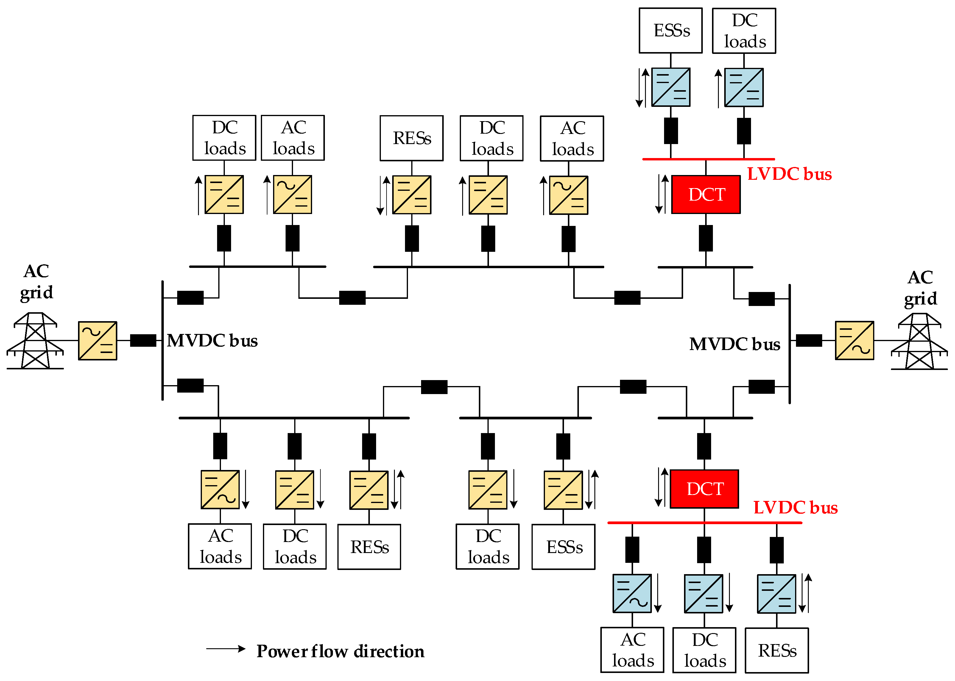
In the early years, most studies on DC distribution systems focused on low-voltage DC (LVDC) bus microgrids [17,18,19]. However, in recent years, with the rapid development of power electronics technology and its successful application, the DC power distribution technology in the medium-voltage DC (MVDC) field has become increasingly mature [20]. Nowadays, many demonstration projects of medium/low-voltage DC (M-LVDC) distribution systems have been constructed [21,22]; one typical example was built in Suzhou, China, as shown in Figure 1, and consisted of a MVDC bus and a LVDC bus. The key equipment in a DC distribution system is the DC transformer (DCT), and several DCTs were installed to interconnect the MVDC bus and LVDC bus [23].
The DCTs are constructed based on DC–DC converters, which have a long history of use in low-voltage applications. Different kinds of DC–DC converters have been researched [5,6,24,25,26] and have been implemented in DC microgrids for accessing loads, ESSs, and RESs [27]. However, none of these converters can serve as permanent interfaces between the MVDC bus and the LVDC bus, and they cannot meet the application requirements of DCTs in flexible M-LVDC distribution systems [17], such as a high conversion gain, high power ratings, high-voltage application [5,28], etc. DCTs combine power electronic converters and high-frequency transformers and can convert one type of DC electricity into another via power electronic circuits [4,23,29,30]. Compared with traditional line frequency AC transformers, the DCT is required to achieve high-gain control of the terminal voltages and current, as well as full-range bidirectional control of the power flow, while providing galvanic isolation [30,31]. In addition, due to the fault ride-through (FRT) requirement of M-LVDC distribution, the DCT should have the function of output current limiting and fast fault isolation [5].
This paper summarizes and analyzes the research status of DCT in DC distribution systems and introduces the basic features of DCTs. The DCT topology is classified according to the application scenarios, and the core problems faced by different DCTs are comprehensively analyzed, such as control targets and FRT requirements. The control strategies of the DCT in transient and steady-state operations are thoroughly researched, and the control schemes for the cascaded DCT are fully considered. The engineering application examples of DCT are introduced by interpreting the demonstration project. Finally, the developing challenges of DCT are discussed, and the development trend of DCT is proposed. In the rest of this paper, the technical requirements and features of the DCTs in M-LVDC distribution systems are summarized in Section 2, the typical structures for DCTs are demonstrated in Section 3, the control strategies for DCTs are introduced in Section 4, the engineering applications of DCTs are given in Section 5, the developing trends of DCTs are discussed in Section 6, and finally, the conclusions are drawn in Section 7.
2. Features of DCTs in M-LVDC Distribution Systems
DCTs play essential roles in M-LVDC distribution systems. This section provides a summary of the features that DCTs should have.
2.1. High Dynamic Performance and Bidirectional Power Flow
In DC distribution systems, the RESs, ESSs, and DC loads, such as EV charging piles, need to exchange energies with each other quickly. Furthermore, the stability of the DC bus needs to be guaranteed. Thus, a fast dynamic response is a basic requirement for DCTs. The dynamic performance of DCTs directly affects the power supply reliability and voltage quality of the distribution system, which depends on the control method of the DCTs. Multi-loop control strategies are more effective in improving the dynamic performance of DCTs than single-loop ones. The outer voltage loop is normally used to produce the current reference for the inner current loop, whereas the inner current loop is designed to meet the requirement of a fast dynamic response of the converter’s transmission power [32]. In addition to this, sliding mode control, dynamic evolution control, model predictive control, fuzzy control, and boundary control can also lead to a high dynamic performance [6]. Moreover, direct power control is a practical and effective control method to improve the dynamic response of DCTs [33], enabling decoupling between the power and actual control variable, and it can cooperate with the control strategies mentioned above to further improve the fast dynamic response of the DCT.
Fast switching between a forward and backward power flow is necessary for DCTs [34]. From the perspective of normal operations, on the one hand, DCTs should operate in the forward direction—that is, from the MVDC bus to the LVDC bus—to provide power support; on the other hand, DCTs should have a backward operating capability to access ESSs for the DC grids. From the perspective of a fault situation, DCTs with the bidirectional power flow feature are appreciated as an excellent solution to compensate for faults in MVDC or LVDC buses [5], which makes it possible to bypass the faulted unit when the rest of the system operates normally, providing high reliability. When external faults occur, such as the DC bus short-circuiting, DCTs with a bidirectional power flow enable rapid electrical disconnection between the MVDC and LVDC buses [35].
2.2. High-Frequency Isolation
Galvanic isolation is necessary to provide safety and flexibility for DCTs [36]. From the perspective of normal operations, isolation can reduce the voltage ratings and the losses of power semiconductor devices on the low-voltage side and achieve a high voltage conversion ratio [6]. From the perspective of faulty situations, isolation can isolate faults in MVDC or LVDC terminals from each other, particularly in applications with a high voltage ratio [5]. More importantly, isolation permits the construction of DCTs by series and parallel connections of power conversion modules. In addition, in multi-input or multi-output DCTs, isolated terminals can isolate faults caused by possible short-circuiting in the source and load branches. Isolated structures can also provide different grounding platforms in DC network interconnections.
Typically, isolation is achieved by DC–AC–DC conversion, which consists of two power stages of AC–DC conversion. Between these two stages, high-frequency AC transformers can be used [37]. Most converters utilizing transformers can be categorized as dual active bridges (DAB) due to the similarities of the DC–AC and AC–DC stages, regardless of the bridge types [5,17]. To achieve high-speed regulation, high-frequency isolation is preferred to medium-frequency isolation. However, it is a huge challenge to produce high-frequency AC transformers for power ratings larger than 100 kW, because the loss of the magnetic core of the AC transformer is very high [38].
2.3. High Voltage Gain and High Power Ratings
The voltage levels of the DC buses that the DCT connects determine the voltage gain that the DCT should provide. For example, in the DC distribution system project in Suzhou, China, the voltage level of the MVDC is 10 kV, and the voltage level of the LVDC is 750 V; the DCTs are then expected to have the capability of converting 10 kV into 750 V. The power rating of the DCT is normally more than 1 MW [39].
The voltage gain of the DCT can be achieved by adopting a transformer with a high turn ratio. However, a cascaded structure through series and parallel connections of two or more converter modules is a more practical and effective way to achieve a high voltage gain and power rating [40].
In conclusion, the dynamic performance of DCTs directly affects the power supply reliability and voltage quality of the distribution system; thus, making a fast dynamic response is an essential requirement for DCTs. The diversity of application scenarios requires that DCTs have bidirectional power capability. High-frequency isolation is necessary for DCTs to ensure safety and flexibility, which is the basis of normal operations and fault isolation. Since there are also many different voltage levels in the DC distribution network, the DCTs should have a high-voltage conversion ratio and high-power level. These characteristics and requirements of DCTs are related to the topology and control method of DCTs, which will be given below.
3. Typical Topologies of DCTs in M-LVDC Distribution Systems
How to construct a DCT topology with excellent performance has become a research hotspot in recent years [23]. This section gives a brief introduction of the typical topologies of DCTs for M-LVDC distribution systems, which can be divided into three categories:
- (1)
- Input-Series–Output-Parallel (ISOP) structure;
- (2)
- Modular Multi-level Converter (MMC);
- (3)
- Hybrid structure.
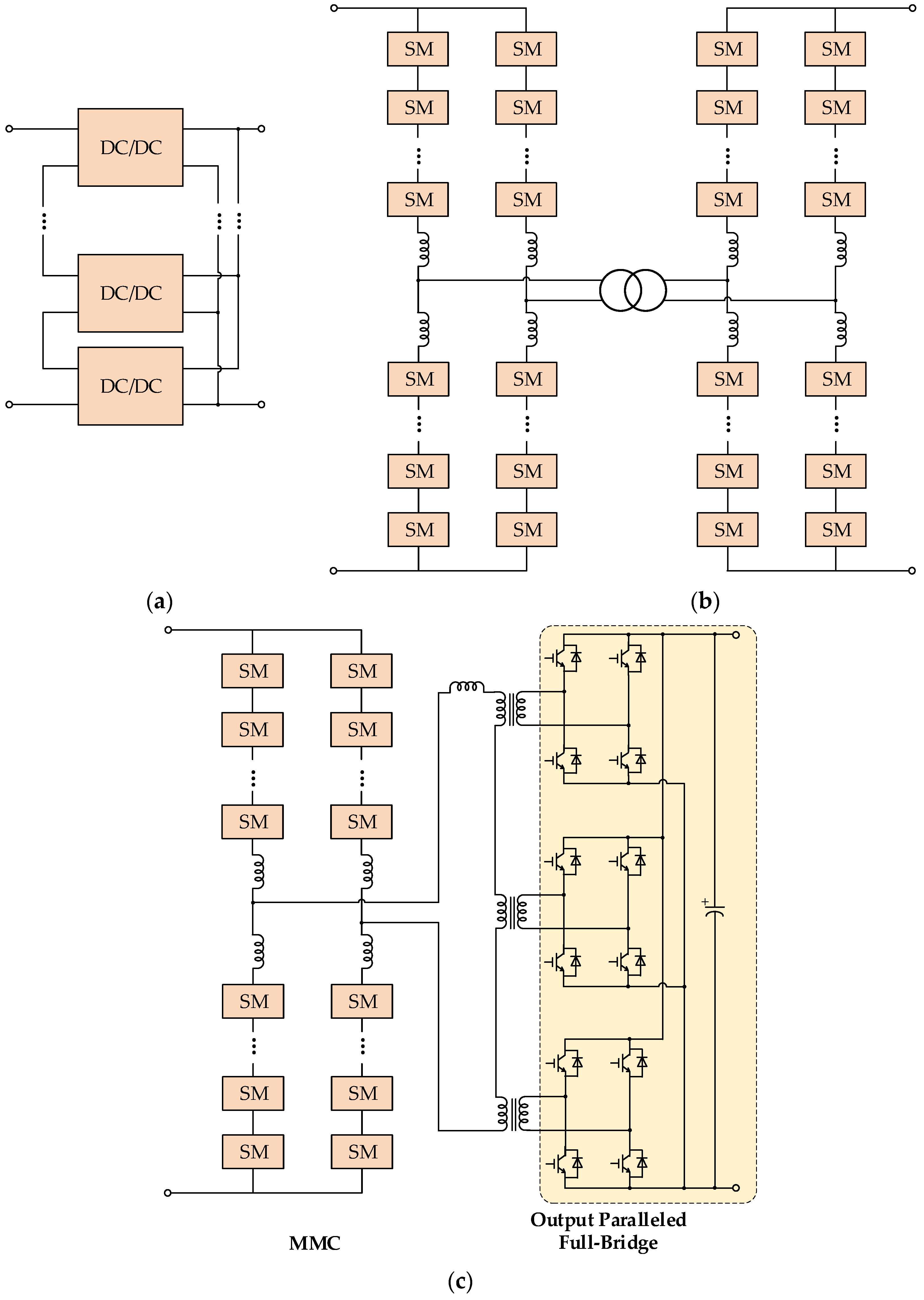
Figure 2 shows the structures of ISOP, a front-to-front MMC (F2F-MMC), and a typical hybrid structure based on MMC and full-bridge (MMFB).
3.1. ISOP Topology
From the perspective of power conversion, the ISOP-DCT requires both a high-voltage bus and large power transmission capacity with the help of modularization [23,41]; thus, the requirements of high voltage gain and high power ratings can be satisfied.
From the perspective of power devices, the ISOP-DCT overcomes the shortcomings of the high-voltage stress of power switches; thus, high-frequency and low-voltage rating switches can be applied to improve the power density and dynamic response speed of DCTs [42]. From the perspective of design and production, the ISOP-DCT facilitates the desired levels of redundancy; moreover, modules of the same type can shorten the period of development and reduce costs [43]. The high-frequency isolation transformer in each submodule (SM) can significantly improve the dynamic performance. However, they should withstand medium-voltage terminal voltage stress while transmitting merely partial power of the DCT, which substantially increases the cost and volume [23].
Two promising converters that can be used for modules of cascaded structure DCTs are the dual active bridge (DAB) and dual bridge series resonant converter (DBSRC). By far, the DAB is a more mature converter than the DBSRC, because the transient process of the DBSRC is complex and hard to control [44]. Now, multi-level and multi-phase DAB converters are emerging that can further improve the voltage level and power density of ISOP-DCTs but are still in the development stage.
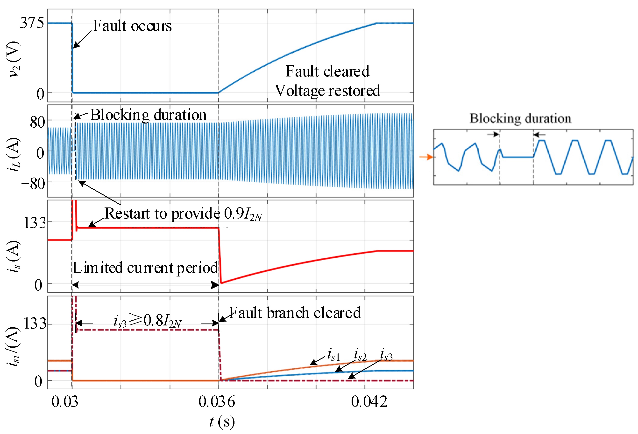
One challenge for ISOP-DCTs is that the concentrated DC capacitor on the terminals makes it difficult to achieve fault ride-through (FRT) [45,46], and an additional DC breaker is required to block the fault overcurrent. It was revealed in [47] that, in a breaker-less shipboard MVDC system, the ISOP-DCT can also achieve fault current control, even though the DC capacitors of the ISOP-DCT are discharged to the DC grid under fault conditions. However, this characteristic needs to be reinvestigated in M-LVDC distribution systems. Reference [35] proposed a FRT method for a single DAB converter, indicating that the internal and external fault currents can be eliminated in one control period by blocking the switching signals and then restarting the circuit to provide the fault criterion current to the fault branch. The simulation results are given in Figure 3, which can also be implemented in the ISOP-DCT.
3.2. MMC Topology
The MMC uses SMs to replace switches in a single converter, which improves the voltage gain and power ratings of DCTs greatly. In addition to this, it can utilize a lumped transformer, which has the advantage of isolation. The arrangements of SMs in one stack can combine the reliability advantages of the modular design with the benefits of a high effective switching frequency [48].
FRT capability is a major challenge against the widespread adoption of MMCs in distribution projects [49]. Traditional FRT methods for the existing MMC-HVDC projects rely on AC circuit breakers [50] or DC circuit breakers [51]. However, the mechanical AC circuit breaker has a long response time, and the system faces great risks before the fault is cleared. DC circuit breakers that cooperate with fault current limiters could clear and isolate DC faults more efficiently and quickly [51]. However, due to the high cost, DC circuit breakers are not widely used. In addition, the FRT methods relying on breakers may lead to a long duration interruption [52]. Therefore, they are not preferable for nonpermanent DC short circuit faults. The potential technical FRT solution for MMC is utilizing the MMC system submodules to block the DC side fault, which has fast response characteristics.
Due to the single-directional conduction characteristic of the diode in the half-bridge structure, the traditional half-bridge submodule (HBSM)-based MMC (HB-MMC) cannot clear a fault current by blocking switching devices in the case of DC short circuit faults. Therefore, several MMC submodule topologies with fault current limitation capability have been proposed in recent years, such as the full-bridge submodule (FBSM) topology and clamped double submodule (CDSM) topology [50]. These submodule topologies allow the MMC to cut off the fault current flowing path by inserting a back EMF into the fault circuit and isolating the fault point or fault line without expensive DC circuit breakers. However, a significant penalty in terms of additional hardware cost and power losses is involved in expanding the submodule topologies. For example, the CDSM topology could imply a 35% increase in losses compared to the conventional HBSM configuration.
In general, the MMC has been widely used in HVDC flexible transmission to interconnect MVDC distribution grids and HVDC transmission grids [34]. However, compared to ISOP-DCTs, when it comes to M-LVDC distribution systems, the control complexity and high cost limit the application of MMC-DCTs [45]. Medium-frequency technology for the MMC has a long way to go for industrialization; meanwhile, the large volume of the MMC decreases the power density.
3.3. Hybrid Topology
The hybrid topology can combine the advantages of different topologies, such as the MMFB structure proposed in [53]. There is a single-phase MMC inverter on the MVDC side and, hence, inherent in the advantages of MMC. On the LVDC side, MMFB replaced the MMC bridge with a full bridge, decreasing the number of switches. The MMFB has a low circulating current and a high-power factor. It can be used as the DC circuit breaker to cut off the connection with the MVDC side when a short circuit fault occurs in the distribution system. A redundancy design can be implemented to improve reliability in the case of partial module failure [53]. However, the switching performance of MMFB becomes terrible, and the loss increases when the MVDC voltage fluctuates [54]. The voltage conversion ability of MMFB can be improved by quasi-square wave modulation [45], which decreases the voltage stress of the switches.
In conclusion, the comparisons of the DCT topologies are listed in Table 1. The ISOP-DCT structure meets the requirements of a high-power rating, high voltage gain, fast dynamic response, high-frequency isolation, and bidirectional power flow, which is an excellent solution to DCT. The performance of ISOP-DCT can be further improved by developing multi-level and multi-phase DAB submodules. However, the FRT capability is still an urgent problem for ISOP-DCT due to the concentrated DC capacitor on the terminals. The MMC structure is superior in high voltage gain and high-rated power, and its FRT technology is more mature than ISOP-DCT, but it still has a long way to go. However, the cost, volume, power density, and medium and high-frequency technology limit the application of MMC in DC distribution. By reasonably combining the advantages of ISOP and MMC, it is also an attractive scheme to implement DCT with a hybrid topology.
4. Control Strategies
The DCT control strategies can be divided into steady-state control strategies and transient control strategies, and in recent years, control strategies for cascaded DCT systems have been put forward [55]. The steady-state control strategy mainly aims at improving the operational efficiency of the DCT, while the transient control strategy is mainly used to ensure stable operation of the DCT under multiple working conditions and modes, including soft start, step change in the transmission power, and other situations. Both steady-state control and transient control aim to improve the performance of the individual DCT, and cascaded-system control strategies aim at dealing with the interaction problems between the DCTs and external circuits. This paper focuses on the control strategies of ISOP-DCTs.
4.1. Steady-State Control Strategy
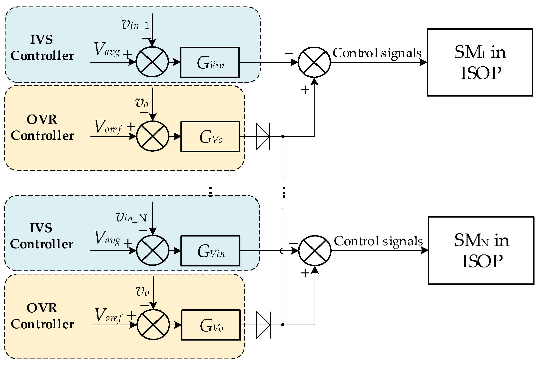
One critical challenge for the steady-state control of ISOP-DCTs is to ensure voltage sharing at the series ports and current sharing at the parallel ports among the constituent modules while achieving a good dynamic performance in terms of output voltage regulation (OVR) [56]. For an ISOP-DCT, once input voltage sharing (IVS) among the modules is achieved, output current sharing (OCS) is achieved nearly automatically. There are several kinds of control strategies for IVS/OCS in an ISOP-DCT, which can be divided into decentralized control strategies and master–slave control strategies [57].
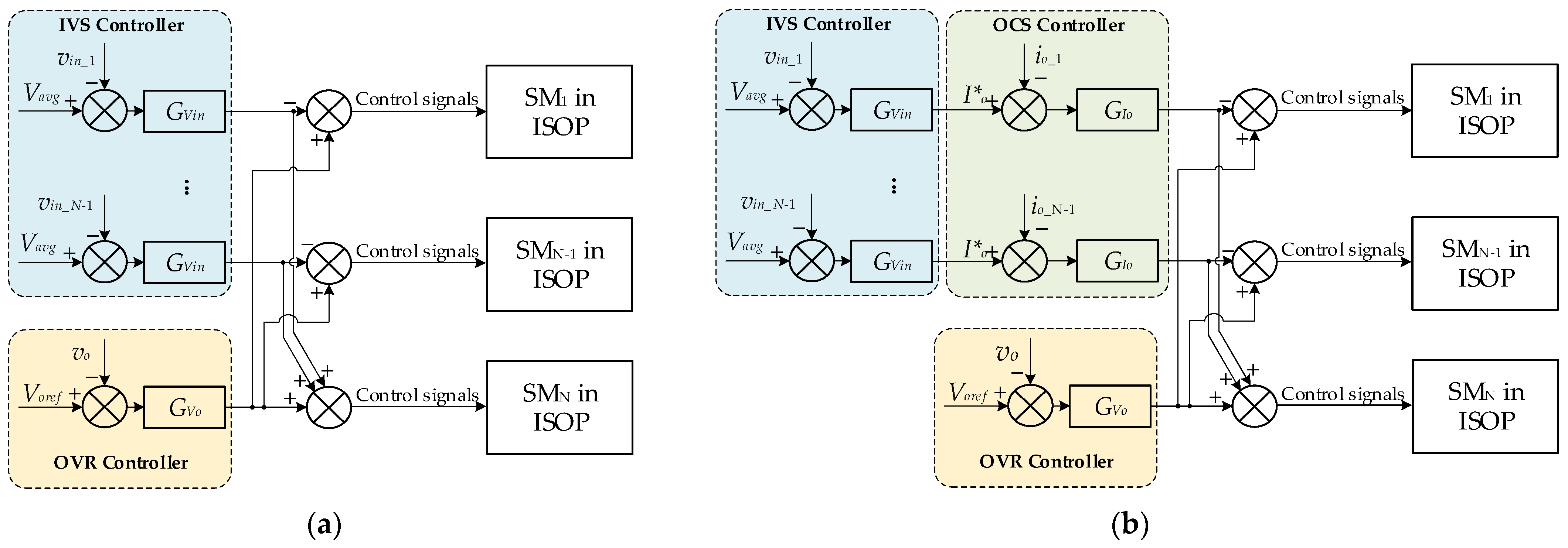
Master–slave control strategies can obtain good characteristics by adding specific sharing regulators for each module, such as an IVS controller based on the input voltages of modules or an OCS controller based on the output currents of modules [37]. However, it was revealed that the ISOP is unstable with the OCS control only, whereas it is stable with IVS control [58,59]. Therefore, OVR–IVS control is a widely used strategy for the ISOP-DCT, but the coupling between the OVR controller and IVS controller should be considered. A typical control structure is shown in Figure 4, where, for an ISOP-DCT consisting of N modules, decoupling can be achieved by adopting N-1 IVS controllers and one OVR controller. For modules No. 1 to No. N-1, the control signal is the output of the OVR controller minus the output of its IVS controller. For module No. N, the control signal is derived from the sum of the outputs of the N-1 IVS controllers and the output of the OVR controller. To improve the dynamic speed, the OCS controller can be imported into the OVR–IVS control; therefore, OVR–IVS–OCS triple-loop control is also a good solution [32]. However, with an increase in the number of modules, the complexity of the master–slave control is increased, and the reliability of the system is decreased [58]. For example, the ISOP system will collapse if the common OVR controller goes wrong. To deal with this problem, a decentralized form is more popular in situations with a high number of modules.
The decentralized OVR–IVS control is an updated version of the master–slave OVR-IVS control, where each module has their own OVR controller and IVS controller, and the outputs of all OVR controllers are compared by a diode to ensure that only the OVR with the highest output signal is active at any time, as shown in Figure 5. The distributed modular OVR–IVS control has the following advantages [56]:
- (1)
- All modules are self-contained and standardized;
- (2)
- Ease of expanding the power capacity;
- (3)
- High redundancy.
Other decentralized control strategies, such as input voltage droop control and output current inverse droop control, which are realized by programming a positive/negative input impedance, also have the advantages of no control interconnections between modules and simple structures. However, there is a tradeoff between IVS/OCS and OVR performance in droop control [56,60]; that is, the better the IVS or OCS performance, the worse the OVR performance.
All in all, a comparison of the ISOP control strategies is given in Table 2.
Studies on the efficiency optimization of DCTs mainly focus on DAB converters. There are several kinds of control modulations for the DAB. The single-phase shift (SPS) modulation is easy to implement [61], but the inductor current cannot be controlled. Moreover, when the DAB converter works in a state of voltage mismatch, there is a large internal backflow power, which increases the current stress of the converter and reduces the operational efficiency of the converter. For dealing with these problems, extended-phase shift (EPS), dual-phase shift (DPS), and triple-phase shift (TPS) modulations were developed, which increase the control freedom and can achieve efficiency optimization. The loss of the DAB converter mainly includes on-state loss and switching losses of power devices, conduction loss, and magnetic loss of the inductor and transformer. In order to optimize the above four parts of the loss, a number of optimization objectives are selected, mainly including a reduction in the backflow power, current stress, effective value of the current, average value of the current, etc. For example, the current stress was optimized in [62,63,64] under DPS, EPS, and TPS, respectively, and [65,66] optimized the backflow power of the DAB under TPS and EPS, respectively.
There have been many achievements made in research to optimize the efficiency of DAB converters, but there are still many problems. In existing studies, optimization of the backflow power of DAB converters usually only considers the input side. In practice, there is also backflow power flowing from the load to the input side on the output side. It is not recommended to eliminate the backflow power completely, because it can enable power devices to achieve zero voltage switching (ZVS). In addition, by comparing different optimization goals, it can be found that the optimal operating points are not the same, and different optimization objectives have great differences in selecting the phase shift ratios for the same optimal operating point. On the other hand, it is difficult to optimize the on-state loss and switching loss at the same time in practical applications, so it is necessary to choose optimization targets firstly in practical applications. In high-voltage and high-power applications, the switching frequency of power devices is relatively low, and the on-state losses of power switches account for a large part of the total loss, so the on-state loss is optimized first. In low-voltage and low-power situations, the power devices operate at a higher switching frequency, and the transient loss is the main part of the total loss, so soft switching of the device should be given priority.
4.2. Transient-State Control Strategy
During the transient processes of the DCT, such as startup and load switching, a transient DC bias component will appear in the inductor current. This is due to the asymmetry of the voltage waveform of the inductor in the transient process. The DC bias component increases the current stress of the switching device and even leads to magnetic saturation of the transformer, which affects the stable operation of the DCT. The methods of eliminating DC bias components can be divided into hardware elimination and software elimination. The hardware elimination method usually adds a direct divider capacitor inside the submodules of the DCT, but the direct divider capacitor reduces the power density of the DCT and changes the operation characteristics. Therefore, in the existing literature, software elimination is a more practical way to eliminate the DC bias component.
The authors of [67] derived a time domain expression of the transient DC bias current in a DAB based on the Fourier series and revealed the relationships between the transient DC bias current and the abrupt change in phase shift angles. Then, a DC bias elimination scheme was proposed by adjusting the phase shift angles twice a period to ensure symmetry of the voltage waveform of the inductor, which can guarantee that the DAB will diminish the transient process within half a switching cycle. Therefore, it can ensure the safety and reliability of the DAB and improve its dynamic performance. The same approach can be applied to a resonant-type DAB [44], which is given in Figure 6a, where the shadows represent the regulation of the transient control scheme. The simulation results are given in Figure 6b, where the transient current and voltage in resonant-type DAB can be eliminated in one period.
4.3. Cascaded System Control Strategy
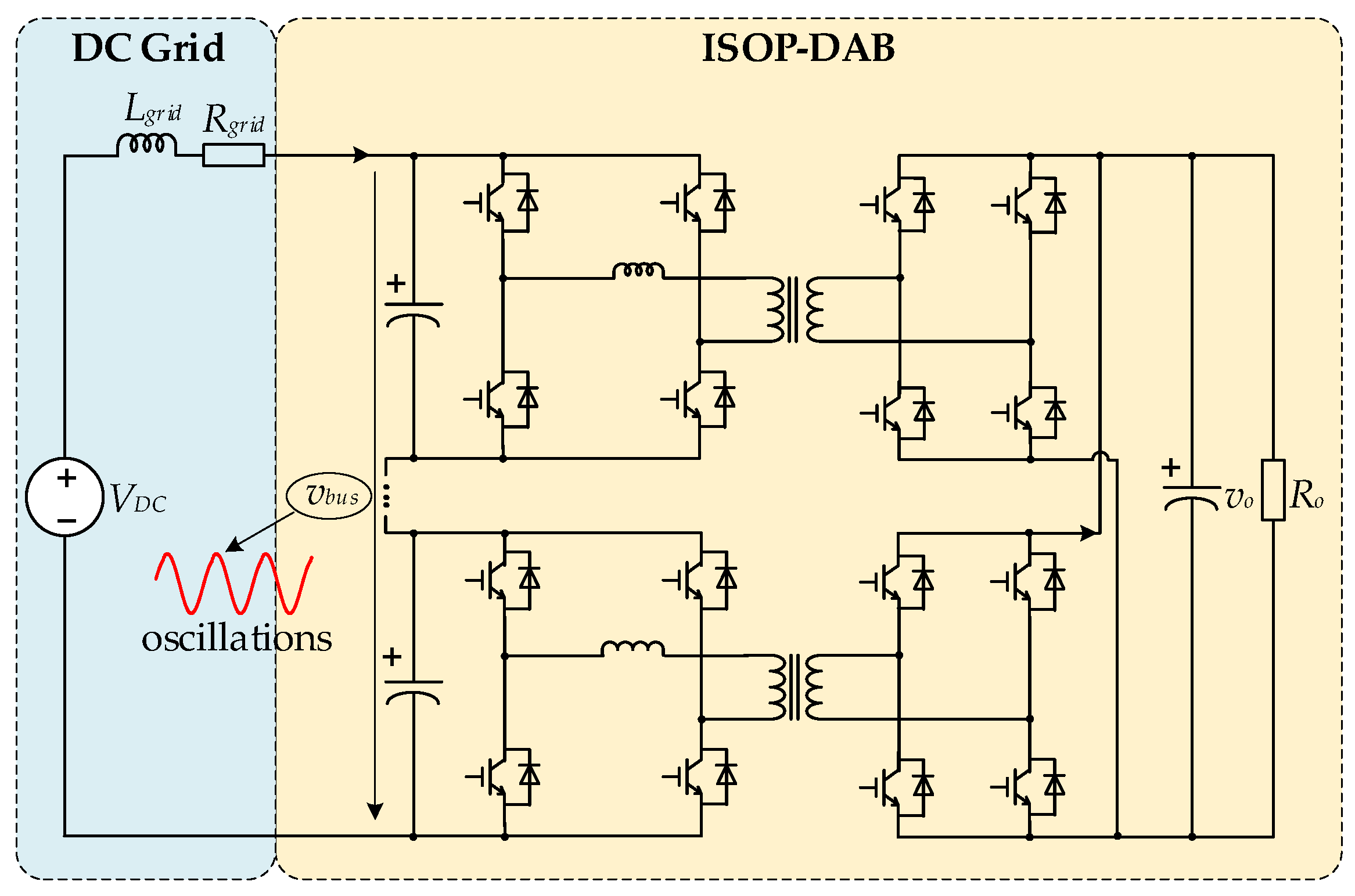
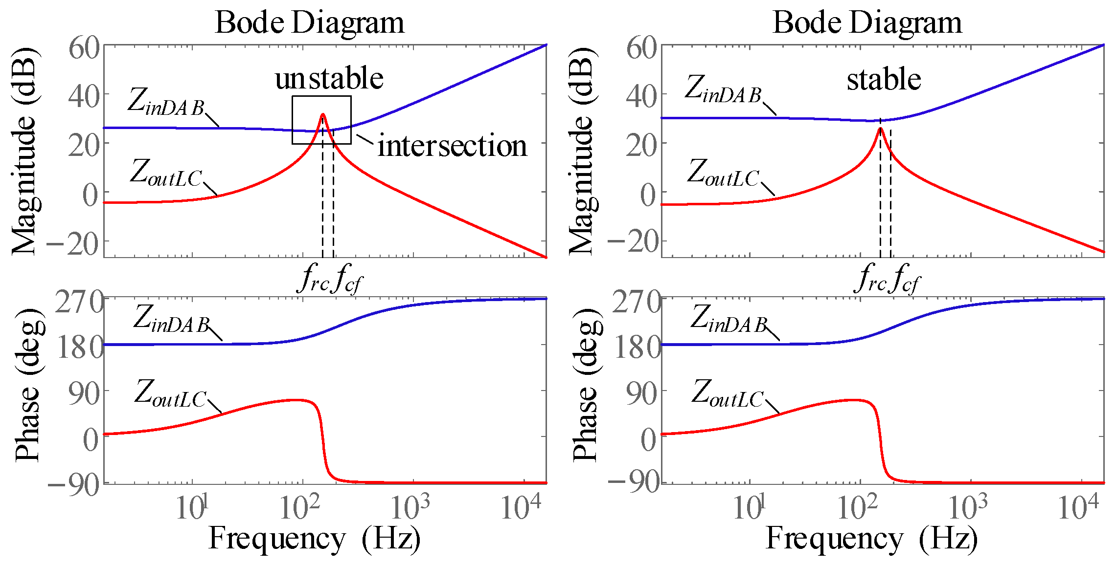
In applications, the DCT does not work individually but is cascaded with other converters, or there exist equivalent inductance and resistance of the transmission line on the input port, thus forming a cascaded system. For example, a DCT with an ISOP-DAB structure involved in an M-LVDC distribution system can be drawn as a cascaded structure, shown in Figure 7, where Lgrid and Rgrid are the equivalent inductance and resistance, respectively, on the transmission line. In a cascaded system, instability and resonance are possible when the output impedance of the source converter and the input impedance of the load converter are not matched due to the Nyquist criterion. For example, in the cascaded system consisting of a LC filter and DAB converter (LC-DAB), ZoutLC(s) is the output impedance of the LC filter, ZinDAB(s) is the input impedance of DAB converter; when |ZoutLC(s)| < |ZinDAB(s)| for the whole frequency domain range of LC-DAB is satisfied, the system is stable, unless it is unstable, as illustrated in Figure 8.
Therefore, it is necessary to derive the input/output impedance model of the DCT and reshape the impedance to meet the stability requirements. The impedance reshaping can be realized by both active damping and passive damping methods. Passive damping is not recommended, because it would introduce additional cost, volume, and power losses [68]. The usage of active damping has become quite common, because it is essentially realized by introducing a control loop into the original control scheme without any power losses [69]. By reshaping the output impedance of the source converter, the dynamic performance of the load converter can be preserved [70]. However, when the source converter is the LC filter, as shown in Figure 7, its output impedance cannot be reshaped by active damping. Therefore, the input impedance of the load converter must be reshaped. Reference [71] proposed a virtual current series impedance control to reshape the input impedance of DAB, ensuring both a fast dynamic performance and the stability of the cascaded LC-DAB system, which can be expanded to the cascaded ISOP-DAB structure. To improve the stability of the DC microgrid, [72] points out that the active damping method can be implemented on the power supply side, load side, and the intermediate level. This idea can also be used in the DC distribution network.
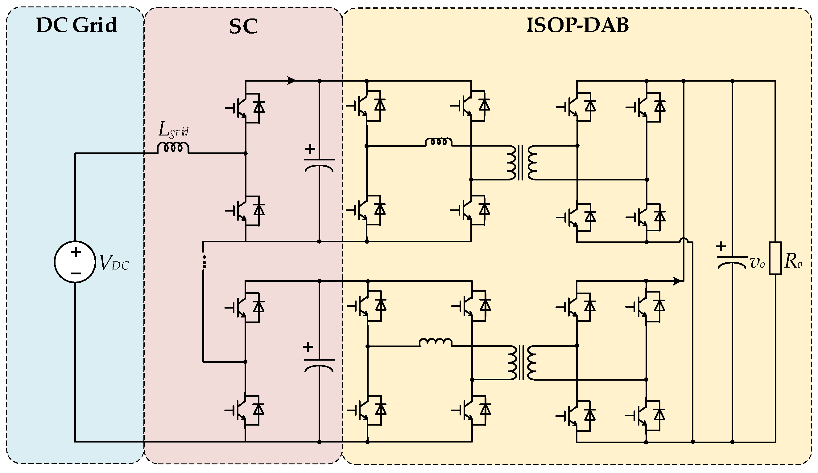
In recent years, switched capacitor (SC) modules have been likely to cascade with ISOP-DCTs to enable the DCTs to disconnect from the MVDC distribution grid effectively as a DC breaker when a short fault occurs on the MVDC side to enhance the power transfer capacity [55], as shown in Figure 9. Moreover, by adjusting the control signal of the SC module, redundancy can be achieved when some SMs in the ISOP fail. However, a large inductor has to be added in front of the SC modules to suppress the current fluctuation [73]. The phase-staggered modulation method was proposed in [73] to suppress current fluctuations effectively, and the cascaded system can employ smaller inductors that also decrease the volume and cost of the system.
In summary, when controlling the DCTs, their own characteristics, such as the steady-state and transient characteristics, and the interactive characteristics of DCTs, such as the cascaded situation, must be considered. The steady-state control method needs to consider two aspects: the system aspect requires OVC and IVS, and the module aspect requires efficiency optimization. The transient control methods aim to eliminate the DC bias components in the high-frequency voltages or currents, which are easy to achieve in single-phase two-level converters. However, with the development of multi-phase and multi-level converters, the corresponding transient control methods must be proposed. The cascaded control method improves the stability of the cascaded system through active damping, which depends on impedance modeling technology. However, impedance modeling of DCTs is not yet mature.
5. Engineering Application
The theoretical research of DCTs has been listed above. However, many differences exist between academic research and practical engineering applications.
For example, in 2021, the State Grid of China Jiangsu Electric Power Co., Ltd., Nanjing, China, invested in the demonstration project of M/LVDC distribution system in Wujiang City, Suzhou, with a cumulative connected DC load of 10.51 MW, PV power of 6.21 MW, and ESS of 2 MWh. In the DCT part, the ±10 kV medium-voltage DC voltage is reduced to the ±375 V DC voltage level through the megawatt medium-voltage DC transformer for easy access on the power side. The project adopts multiple structures according to the characteristics of different application scenarios:
- (1)
- Pure PV accesses scenario
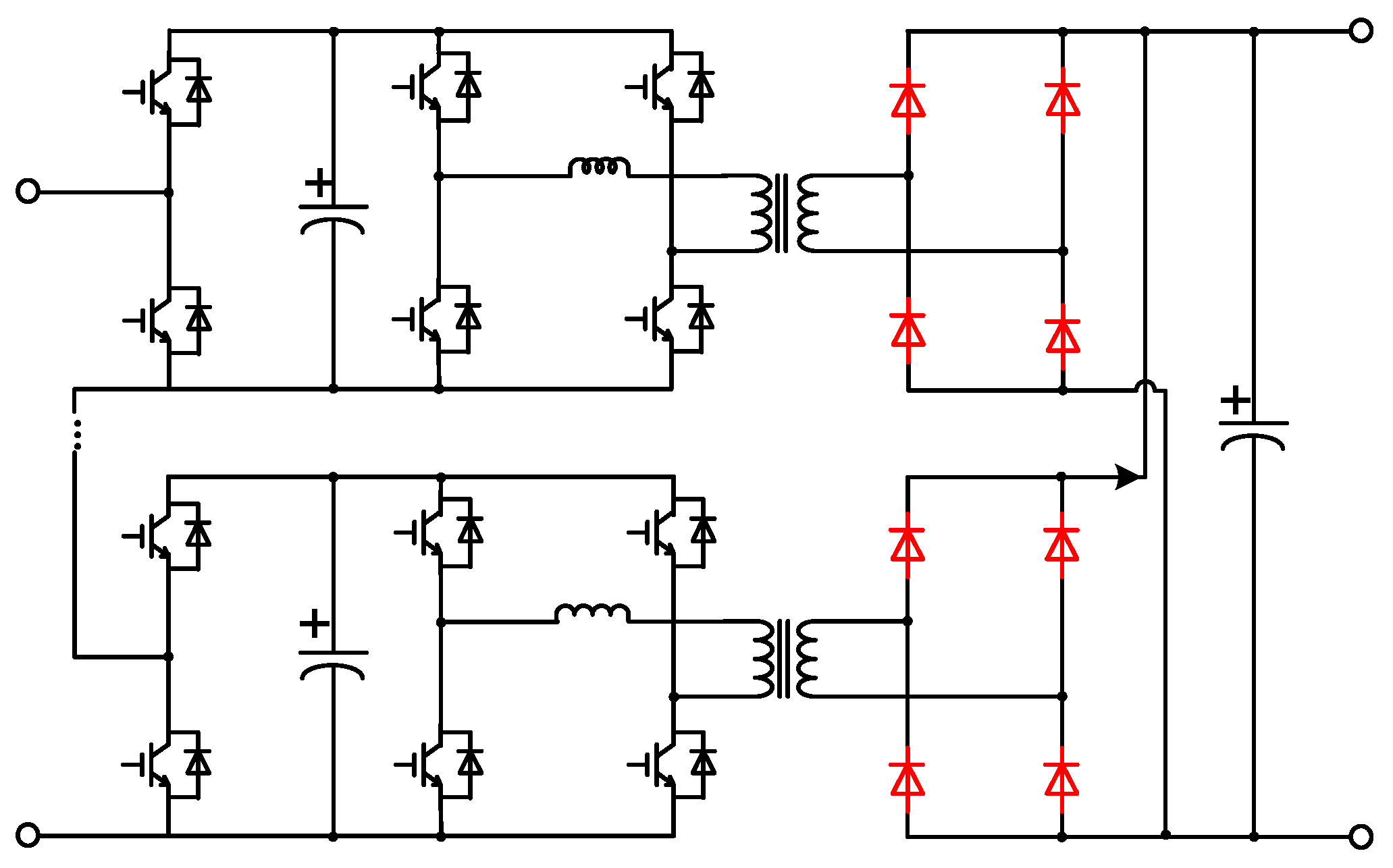
As shown in Figure 10, the medium-voltage side adopts a half-bridge module structure to realize fault blocking, online redundancy, voltage equalizing control, etc. At the low-voltage side of the DCT, a rectifier full bridge replaces the active full bridge to realize one-way power transmission, and the ISOP structure is used to achieve a higher voltage transfer ratio.
- (2)
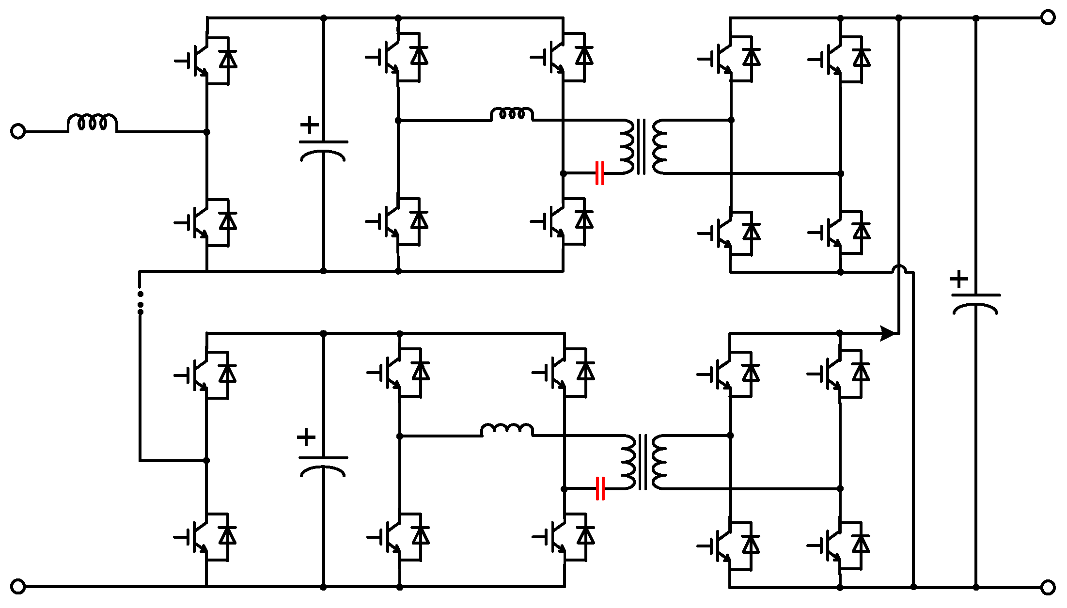
- Hybrid PV, ESS, and various industrial load access scenarios
As shown in Figure 11, the ISOP structure is used to achieve a higher voltage transfer ratio, and the SC + resonant DAB submodule is taken to realize the bidirectional power transmission and soft switching.
- (3)
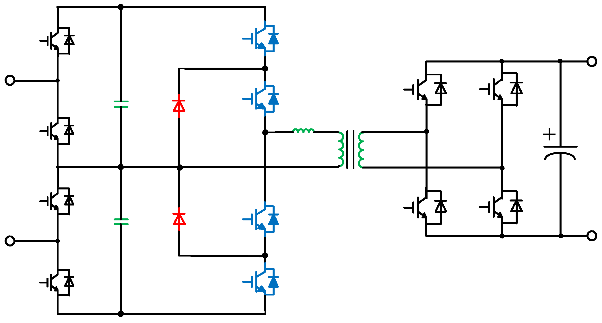
- Charging pile accesses scenario
The charging pile has high light-load efficiency requirements but low reliability requirements. Therefore, to reduce the volume and manufacturing costs of DCT, a three-level structure can replace the traditional two-level structure to build the ISOP, effectively reducing the number of power modules and significantly reducing the volume of DCT. The three-level structure submodule is given in Figure 12.
- (4)
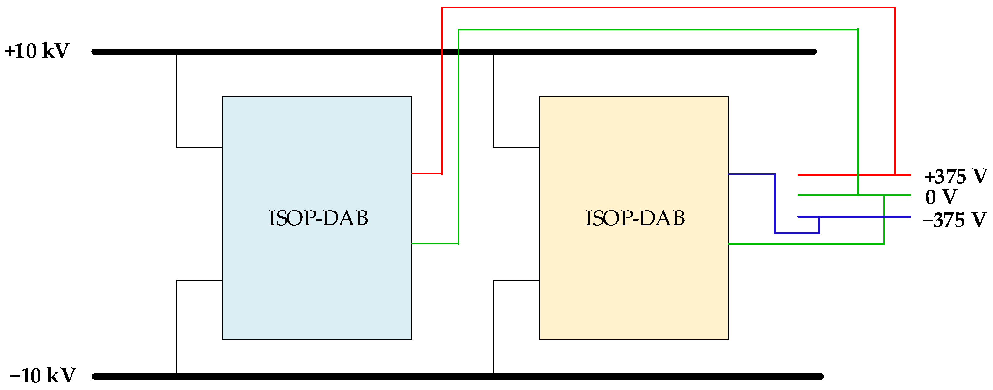
- Residential, commercial, data center, and other application access scenario
These application scenarios have many voltage levels and high reliability requirements. For example, the data center has to access 750 V, and the residential loads have to access 375 V. Therefore, the ISOP-DCT can be connected as an actual bipolar structure to increase reliability, as shown in Figure 13.
The demonstration project fully considers DCTs with high reliability, high efficiency, and stable operations in multiple application scenarios, which have excellent guiding significance for the future research and application of DCTs.
6. Challenges and Future Works
Great breakthroughs have been made in theoretical research and engineering sample machine developments of DCTs. However, there are still challenges for DCTs:
6.1. Challenges
- (1)
- Design and manufacture of high-frequency transformers
With increasing the operating frequency, the parasitic parameters of the transformers have a great influence on the operating characteristics of power devices and further influence the performance of DCTs [74]. High-voltage and high-power applications may cause a breakdown of the insulation materials of the transformer. With the requirement of the power density, the transformer size is expected to be reduced greatly, thus reducing the heat dissipation surface volume of the transformer, resulting in low efficiency [75].
- (2)
- Limitations of DCT efficiency optimization algorithm
Multiple optimization goals of DCTs cannot be achieved at the same time, and a unified conclusion on an efficiency optimization method for DCTs is lacking. Moreover, there is no precise physical interpretation of quantities such as the backflow power of a DCT.
- (3)
- Immature FRT method
The significant current rise rate and rapid voltage drop in the DC system is a considerable challenge to the design of the FRT method for DCTs. Due to the lack of fast and reliable DC fault identification and isolation methods, the available FRT methods after a DC fault are primarily based on locking and reclosing [76], which will reduce the power supply reliability.
- (4)
- Disadvantages at device level
With the optimization and improvement of the control methods, the switching device would become the next major factor that limits the performance of DCTs. Silicon-based power devices are currently limited in switching speeds, and the on-resistance and switching loss cannot be neglected. The low-voltage withstanding capability leads to an increase in the number of devices and a reduction in the power density of the DCT. However, due to the size limitations of soft ferrite and amorphous alloy, advanced SiC MOSFET cannot be fully used in high-voltage and high-voltage DCT with high-frequency transformers [74].
- (5)
- Cascaded instability
In a DC distribution system, DC power conversion is realized by multi-level converters so that DCT can form a cascade structure with multiple circuits. However, impedance modeling and control technology are still immature, as each DCT has different impedance characteristics, and the artificial derivation takes a great deal of work. Therefore, DCTs face a more significant risk of cascading instability.
6.2. Future Works
Aiming at the above challenges, the authors have the following outlook for future research:
- (1)
- Improve the design theory and manufacturing method of high-frequency transformers under high-voltage and high-power conditions by analyzing the loss characteristics of magnetic core winding and the aging mechanism of insulation materials under harsh conditions, exploring the high-precision measurement method of parasitic parameters.
- (2)
- Establish a complete and accurate loss model, exploring the core factors affecting the operation efficiency and proposing a global efficiency improvement method for DCTs.
- (3)
- Carry out in-depth research on the fault characteristics of DCTs, including analyses of the operation mechanism of DCTs under fault states, characterization of the operation boundary, and study of the FRT strategy.
- (4)
- Develop the application of wide-bandgap (WBG) power devices in DCTs. SiC power devices have apparent advantages in switching speed, on-state resistance, and switching losses; developing high-voltage SiC-MOSFETs can reduce the number of modules in an ISOP.
- (5)
- Develop an impedance sweep tool for DCTs. Recently, many equipment manufacturers have focused on developing a specialized impedance analysis tool to obtain the input/output impedance by frequency sweeping [77]. In addition to this, equipment that can automatically design a reasonable LC filter and reshape the impedance to achieve stabilization is also a research hotspot.
The authors believe that these future works will deal with the technical bottleneck of DCTs and promote the better development of DC distribution technology.
7. Conclusions
A DCT is an effective electronic device connecting MVDC and LVDC buses in the DC distribution system. The essential functions and characteristics of DCTs were summarized in this paper by analyzing the requirements of the DC distribution system. The existing topologies of DCTs were analyzed and compared based on the essential functions that DCTs should have. The relevant control strategies were researched, including steady-state control, transient control, and cascaded control. The engineering application examples of DCTs were introduced by interpreting the medium and low-voltage DC distribution system demonstration project in Wujiang City, Suzhou. Finally, the challenges faced by DCTs in hardware, efficiency optimization, fault traversal mechanism, device level, and cascade structure were given, and the future development trend was predicted.
Author Contributions
Conceptualization, Y.C. and Y.Z.; methodology, Y.C. and Y.Z.; software, Y.Z.; validation, Y.Z.; formal analysis, Y.C. and Y.Z.; investigation, Y.C. and Y.Z.; resources, Y.C. and Y.Z.; data curation, Y.C.; writing—original draft preparation, Y.C.; writing—review and editing, Y.Z.; visualization, Y.C.; supervision, Y.Z.; project administration, Y.Z.; funding acquisition, Y.Z. All authors have read and agreed to the published version of the manuscript.
Funding
This research was funded by the National Natural Science Foundation of China, grant number 51977092.
Data Availability Statement
Not applicable.
Conflicts of Interest
The authors declare no conflict of interest.
References
- Wu, Q.; Peng, C. Scenario Analysis of Carbon Emissions of China’s Electric Power Industry Up to 2030. Energies 2016, 9, 988. [Google Scholar] [CrossRef] [Green Version]
- Sun, X.; Zhang, B.; Tang, X.; McLellan, B.C.; Höök, M. Sustainable Energy Transitions in China: Renewable Options and Impacts on the Electricity System. Energies 2016, 9, 980. [Google Scholar] [CrossRef] [Green Version]
- Musiał, W.; Zioło, M.; Luty, L.; Musiał, K. Energy Policy of European Union Member States in the Context of Renewable Energy Sources Development. Energies 2021, 14, 2864. [Google Scholar] [CrossRef]
- Khan, S.S.; Wen, H. A Comprehensive Review of Fault Diagnosis and Tolerant Control in DC-DC Converters for DC Microgrids. IEEE Access 2021, 9, 80100–80127. [Google Scholar] [CrossRef]
- Alhurayyis, I.; Elkhateb, A.; Morrow, J. Isolated and Nonisolated DC-to-DC Converters for Medium-Voltage DC Networks: A Review. IEEE J. Emerg. Sel. Top. Power Electron. 2021, 9, 7486–7500. [Google Scholar] [CrossRef]
- Gorji, S.A.; Sahebi, H.G.; Ektesabi, M.; Rad, A.B. Topologies and Control Schemes of Bidirectional DC–DC Power Converters: An Overview. IEEE Access 2019, 7, 117997–118019. [Google Scholar] [CrossRef]
- Das, D.; Hossain, M.J.; Mishra, S.; Singh, B. Bidirectional Power Sharing of Modular DABs to Improve Voltage Stability in DC Microgrids. IEEE Trans. Ind. Appl. 2022, 58, 2369–2377. [Google Scholar] [CrossRef]
- Terawatt-Scale Photovoltaics: Trajectories and Challenges | Science. Available online: https://www.science.org/doi/full/10.1126/science.aal1288 (accessed on 14 October 2022).
- Lainfiesta Herrera, M.; Hayajneh, H.S.; Zhang, X. DC Communities: Transformative Building Blocks of the Emerging Energy Infrastructure. Energies 2021, 14, 7730. [Google Scholar] [CrossRef]
- Zhang, W.; Liu, Y.; Cui, Y.; Zhao, M.; Wei, T.; Chen, Q. Research on Typical Power Supply Mode of DC Distribution and Consumption System. In Proceedings of the 2020 IEEE Sustainable Power and Energy Conference (iSPEC), Chengdu, China, 23–25 November 2020; pp. 491–496. [Google Scholar]
- Yang, W.; Yibin, Z.; Donglai, Z.; Han, H. The Technical Trends and Suggestions on the Development of DC Power Grid. In Proceedings of the 2014 International Conference on Power System Technology, Chengdu, China, 20–22 October 2014; pp. 1975–1979. [Google Scholar]
- Xu, C.D.; Cheng, K.W.E. A Survey of Distributed Power System—AC versus DC Distributed Power System. In Proceedings of the 2011 4th International Conference on Power Electronics Systems and Applications, Hong Kong, China, 8–10 June 2011; pp. 1–12. [Google Scholar]
- An In-Depth Comparison of HVDC and HVAC-Technical Articles. Available online: https://eepower.com/technical-articles/an-in-depth-comparison-of-hvdc-and-hvac/# (accessed on 6 March 2023).
- Yang, W.; Zhang, A.; Song, S.; Zhang, H.; Wang, J. Comparative Study on Radial Topology 10kV AC and ±10kV DC Power Distribution Network. In Proceedings of the 2016 Chinese Control and Decision Conference (CCDC), Yinchuan, China, 28–30 May 2016; pp. 6216–6221. [Google Scholar]
- Liu, Y.; Li, Y.; Wang, Y.; Zhu, J.; Gooi, H.B.; Xin, H. Distributed Real-Time Multi-Objective Control of a Virtual Power Plant in DC Distribution Systems. IEEE Trans. Power Deliv. 2022, 37, 1876–1887. [Google Scholar] [CrossRef]
- Li, Y.; He, L.; Liu, F.; Li, C.; Cao, Y.; Shahidehpour, M. Flexible Voltage Control Strategy Considering Distributed Energy Storages for DC Distribution Network. IEEE Trans. Smart Grid 2019, 10, 163–172. [Google Scholar] [CrossRef]
- Zhao, B.; Song, Q.; Li, J.; Sun, Q.; Liu, W. Full-Process Operation, Control, and Experiments of Modular High-Frequency-Link DC Transformer Based on Dual Active Bridge for Flexible MVDC Distribution: A Practical Tutorial. IEEE Trans. Power Electron. 2017, 32, 6751–6766. [Google Scholar] [CrossRef]
- Pires, V.F.; Pires, A.; Cordeiro, A. DC Microgrids: Benefits, Architectures, Perspectives and Challenges. Energies 2023, 16, 1217. [Google Scholar] [CrossRef]
- Sospiro, P.; Amarnath, L.; Di Nardo, V.; Talluri, G.; Gandoman, F.H. Smart Grid in China, EU, and the US: State of Implementation. Energies 2021, 14, 5637. [Google Scholar] [CrossRef]
- Ruixiong, Y.; Kangsheng, C.; Jianfu, C.; Lu, Q.; Yong, C.; Zhanqing, Y.; Jian, S.; Jian, C. Review of Typical Technical Schemes for Medium and Low Voltage DC Distribution. In Proceedings of the 18th International Conference on AC and DC Power Transmission (ACDC 2022), Online, 2–3 July 2022; Volume 2022, pp. 1015–1022. [Google Scholar]
- Zhao, M.; Yue, Y.; Li, S.; Xiao, D.; Lv, X.; Chen, D.; Dong, S. Feasibility Study of Using Flexible Substations in Distribution Systems in China. In Proceedings of the 2018 2nd IEEE Conference on Energy Internet and Energy System Integration (EI2), Beijing, China, 20–22 October 2018; pp. 1–6. [Google Scholar]
- Kang, J.; Hao, B.; Li, Y.; Lin, H.; Xue, Z. The Application and Development of LVDC Buildings in China. Energies 2022, 15, 7045. [Google Scholar] [CrossRef]
- Jin, H.; Chen, W.; Hou, K.; Shao, S.; Shu, L.; Li, R. A Sharing-Branch Modular Multilevel DC Transformer with Wide Voltage Range Regulation for DC Distribution Grids. IEEE Trans. Power Electron. 2022, 37, 5714–5730. [Google Scholar] [CrossRef]
- Adam, G.P.; Alsokhiry, F.; Al-Turki, Y.; Ajangnay, M.O.; Amogpai, A.Y. DC-DC Converters for Medium and High Voltage Applications. In Proceedings of the IECON 2019-45th Annual Conference of the IEEE Industrial Electronics Society, Lisbon, Portugal, 14–17 October 2019; Volume 1, pp. 3337–3342. [Google Scholar]
- Chen, J.; Nguyen, M.-K.; Yao, Z.; Wang, C.; Gao, L.; Hu, G. DC-DC Converters for Transportation Electrification: Topologies, Control, and Future Challenges. IEEE Electrif. Mag. 2021, 9, 10–22. [Google Scholar] [CrossRef]
- Cheng, X.-F.; Liu, C.; Wang, D.; Zhang, Y. State-of-the-Art Review on Soft-Switching Technologies for Non-Isolated DC-DC Converters. IEEE Access 2021, 9, 119235–119249. [Google Scholar] [CrossRef]
- Fotopoulou, M.; Rakopoulos, D.; Trigkas, D.; Stergiopoulos, F.; Blanas, O.; Voutetakis, S. State of the Art of Low and Medium Voltage Direct Current (DC) Microgrids. Energies 2021, 14, 5595. [Google Scholar] [CrossRef]
- Swaminathan, N.; Cao, Y. An Overview of High-Conversion High-Voltage DC–DC Converters for Electrified Aviation Power Distribution System. IEEE Trans. Transp. Electrif. 2020, 6, 1740–1754. [Google Scholar] [CrossRef]
- Xuan, Y.; Yang, X.; Chen, W.; Liu, T.; Hao, X. A Novel NPC Dual-Active-Bridge Converter With Blocking Capacitor for Energy Storage System. IEEE Trans. Power Electron. 2019, 34, 10635–10649. [Google Scholar] [CrossRef]
- Huber, J.E.; Kolar, J.W. Applicability of Solid-State Transformers in Today’s and Future Distribution Grids. IEEE Trans. Smart Grid 2019, 10, 317–326. [Google Scholar] [CrossRef]
- Guan, Y.; Cecati, C.; Alonso, J.M.; Zhang, Z. Review of High-Frequency High-Voltage-Conversion-Ratio DC–DC Converters. IEEE J. Emerg. Sel. Top. Ind. Electron. 2021, 2, 374–389. [Google Scholar] [CrossRef]
- Wang, Y.; Guan, Y.; Fosso, O.; Molinas, M.; Chen, S.-Z.; Zhang, Y. An Input-Voltage-Sharing Control Strategy of Input-Series-Output-Parallel Isolated Bidirectional DC/DC Converter for DC Distribution Network. IEEE Trans. Power Electron. 2021, 37, 1592–1604. [Google Scholar] [CrossRef]
- Zhong, M.; Ao, Q.; Zhang, W.; Fan, Y.; Meng, W. A Hybrid Control Scheme for the Dual-Active-Bridge Dc-Dc Converter with Fast Dynamic Response and Measurement Noise Suppression. In Proceedings of the 2021 11th International Conference on Power and Energy Systems (ICPES), Shanghai, China, 18–20 December 2021; pp. 30–35. [Google Scholar]
- Cui, S.; Hu, J.; De Doncker, R.W. Control and Experiment of a TLC-MMC Hybrid DC–DC Converter for the Interconnection of MVDC and HVDC Grids. IEEE Trans. Power Electron. 2020, 35, 2353–2362. [Google Scholar] [CrossRef]
- Chen, Y.; Zhang, Y. Fault Characteristics and Riding-Through Methods of Dual Active Bridge Converter Under Short-Circuit of the Load. IEEE Trans. Power Electron. 2021, 36, 9578–9591. [Google Scholar] [CrossRef]
- Suryadevara, R.; Parsa, L. Full-Bridge ZCS-Converter-Based High-Gain Modular DC-DC Converter for PV Integration With Medium-Voltage DC Grids. IEEE Trans. Energy Convers. 2019, 34, 302–312. [Google Scholar] [CrossRef]
- Zhang, Y.; Shi, S.; Xu, D.; Yang, R. Comparison and Review of DC Transformer Topologies for HVDC and DC Grids. In Proceedings of the 2016 IEEE 8th International Power Electronics and Motion Control Conference (IPEMC-ECCE Asia), Hefei, China, 22–26 May 2016; pp. 3336–3343. [Google Scholar]
- Khan, Z.W.; Minxiao, H.; Kai, C.; Yang, L.; Rehman, A. State of the Art DC-DC Converter Topologies for the Multi-Terminal DC Grid Applications: A Review. In Proceedings of the 2020 IEEE International Conference on Power Electronics, Smart Grid and Renewable Energy (PESGRE2020), Cochin, India, 2–4 January 2020; pp. 1–7. [Google Scholar]
- Fan, Y.; Chi, Y.; Li, Y.; Wang, Z.; Liu, H.; Liu, W.; Li, X. Key Technologies for Medium and Low Voltage DC Distribution System. Glob. Energy Interconnect. 2021, 4, 91–103. [Google Scholar] [CrossRef]
- Haris, M.; Asim, M.; Tariq, M. A Review of Non-Isolated High Gain DC-to-DC Converter Topologies. In Proceedings of the 2022 2nd International Conference on Emerging Frontiers in Electrical and Electronic Technologies (ICEFEET), Patna, India, 24–25 June 2022; pp. 1–6. [Google Scholar]
- Zumel, P.; Ortega, L.; Lazaro, A.; Fernandez, C.; Barrado, A.; Rodriguez, A.; Hernando, M.M. Modular Dual-Active Bridge Converter Architecture. IEEE Trans. Ind. Applicat. 2016, 52, 2444–2455. [Google Scholar] [CrossRef] [Green Version]
- Zeng, J.; Rao, Y. Power Optimization Balance Control Strategy for Input-Series-Output-Parallel DAB Converters. In Proceedings of the 2021 IEEE 1st International Power Electronics and Application Symposium (PEAS), Shanghai, China, 13–15 November 2021; pp. 1–4. [Google Scholar]
- Qu, L.; Zhang, D.; Bao, Z. Output Current-Differential Control Scheme for Input-Series–Output-Parallel-Connected Modular DC–DC Converters. IEEE Trans. Power Electron. 2017, 32, 5699–5711. [Google Scholar] [CrossRef]
- Li, Z.; Zhang, Y.; Wu, X.; Yang, J. Control Strategy of Transient Process for Dual-Bridge Series Resonant Converter. In Proceedings of the 2022 IEEE Energy Conversion Congress and Exposition (ECCE), Detroit, MI, USA, 9–13 October 2022; pp. 1–6. [Google Scholar]
- Cheng, S.; Shi, S.; Zhuo, F.; Wang, F.; Zhu, Y.; Zhang, N. A DC Transformer Based on MMC and Full-Bridge Structure with Control Method. In Proceedings of the 2019 10th International Conference on Power Electronics and ECCE Asia (ICPE 2019-ECCE Asia), Busan, Republic of Korea, 27–30 May 2019; pp. 1401–1406. [Google Scholar]
- Wang, Y.; Yang, L.; Wu, Q.; Chen, S.-Z.; Yu, Z.; Guan, Y.; Zhang, Y. A Hybrid Isolated Bidirectional DC/DC Solid-State Transformer for DC Distribution Network. IEEE Access 2021, 9, 159059–159070. [Google Scholar] [CrossRef]
- Xie, R.; Li, H. Fault Performance Comparison Study of a Dual Active Bridge (DAB) Converter and an Isolated Modular Multilevel DC/DC (IM2DC) Converter for Power Conversion Module Application in a Breaker-Less Shipboard MVDC System. IEEE Trans. Ind. Applicat. 2018, 54, 5444–5455. [Google Scholar] [CrossRef]
- Xiang, X.; Gu, Y.; Qiao, Y.; Zhang, X.; Li, W.; He, X.; Green, T.C. Resonant Modular Multilevel DC–DC Converters for Both High and Low Step-Ratio Connections in MVDC Distribution Systems. IEEE Trans. Power Electron. 2021, 36, 7625–7640. [Google Scholar] [CrossRef]
- Wang, Y.; Li, Q.; Li, B.; Wei, T.; Zhu, Z.; Li, W.; Wen, W.; Wang, C. A Practical DC Fault Ride-Through Method for MMC Based MVDC Distribution Systems. IEEE Trans. Power Deliv. 2021, 36, 2510–2519. [Google Scholar] [CrossRef]
- Song, Y.; Luo, Y.; Xiong, X.; Blaabjerg, F.; Wang, W. An Improved Submodule Topology of MMC With Fault Blocking Capability Based On Reverse-Blocking Insulated Gate Bipolar Transistor. IEEE Trans. Power Deliv. 2022, 37, 1559–1568. [Google Scholar] [CrossRef]
- Xu, J.; Zhu, S.; Li, C.; Zhao, C. The Enhanced DC Fault Current Calculation Method of MMC-HVDC Grid With FCLs. IEEE J. Emerg. Sel. Topics Power Electron. 2019, 7, 1758–1767. [Google Scholar] [CrossRef]
- Peng, C.; Li, R.; Cai, X. Reverse Blocking Devices Based Three-Level MMC Sub-Module Topology With DC Side Fault Blocking Capability. IEEE Trans. Power Deliv. 2022, 37, 1866–1875. [Google Scholar] [CrossRef]
- Zhao, B.; Song, Q.; Li, J.; Wang, Y.; Liu, W. Modular Multilevel High-Frequency-Link DC Transformer Based on Dual Active Phase-Shift Principle for Medium-Voltage DC Power Distribution Application. IEEE Trans. Power Electron. 2017, 32, 1779–1791. [Google Scholar] [CrossRef]
- Zhao, B.; Song, Q.; Li, J.; Xu, X.; Liu, W. Comparative Analysis of Multilevel-High-Frequency-Link and Multilevel-DC-Link DC–DC Transformers Based on MMC and Dual-Active Bridge for MVDC Application. IEEE Trans. Power Electron. 2018, 33, 2035–2049. [Google Scholar] [CrossRef]
- Zhao, B.; Song, Q.; Li, J.; Liu, W.; Liu, G.; Zhao, Y. High-Frequency-Link DC Transformer Based on Switched Capacitor for Medium-Voltage DC Power Distribution Application. IEEE Trans. Power Electron. 2015, 31, 4766–4777. [Google Scholar] [CrossRef]
- Ma, D.; Chen, W.; Ruan, X. A Review of Voltage/Current Sharing Techniques for Series–Parallel-Connected Modular Power Conversion Systems. IEEE Trans. Power Electron. 2020, 35, 12383–12400. [Google Scholar] [CrossRef]
- Luo, C.; Huang, S. Novel Voltage Balancing Control Strategy for Dual-Active-Bridge Input-Series-Output-Parallel DC-DC Converters. IEEE Access 2020, 8, 103114–103123. [Google Scholar] [CrossRef]
- Liu, F.; Zhou, G.; Ruan, X.; Ji, S.; Zhao, Q.; Zhang, X. An Input-Series-Output-Parallel Converter System Exhibiting Natural Input-Voltage Sharing and Output-Current Sharing. IEEE Trans. Ind. Electron. 2021, 68, 1166–1177. [Google Scholar] [CrossRef]
- Deng, F.; Zhang, X.; Li, X.; Lei, T.; Wang, T. Decoupling Control Strategy for Input-Series Output-Parallel Systems Based on Dual Active Bridge Dc-Dc Converters. In Proceedings of the 2018 9th IEEE International Symposium on Power Electronics for Distributed Generation Systems (PEDG), Charlotte, NC, USA, 25–28 June 2018; pp. 1–8. [Google Scholar]
- Ding, R.; Wang, F.; Zhang, N.; Shi, S.; Cheng, S.; Zhuo, F. A Decentralized Control Strategy with Output Voltage Deviation-Correction for Input-Series-Output-Parallel DC Transformer Based on Dual-Active-Bridge. In Proceedings of the 2020 IEEE 9th International Power Electronics and Motion Control Conference (IPEMC2020-ECCE Asia), Nanjing, China, 29 November 2020; pp. 2458–2462. [Google Scholar]
- Tiwary, N.; Venkataramana, N.N.; Panda, A.K.; Narendra, A. Direct Power Control of Dual Active Bridge Bidirectional DC-DC Converter. In Proceedings of the 2019 International Conference on Power Electronics, Control and Automation (ICPECA), New Delhi, India, 16–17 November 2019; pp. 1–4. [Google Scholar]
- Ding, J.; Li, G.; Zhang, H.; Zhang, A.; Huang, J. A Novel DPS Control of Dual Active Bridge DC-DC Converters to Minimize Current Stress and Improve Transient Response. In Proceedings of the 2021 33rd Chinese Control and Decision Conference (CCDC), Kunming, China, 22 May 2021; pp. 2130–2135. [Google Scholar]
- Zhao, B.; Yu, Q.; Sun, W. Extended-Phase-Shift Control of Isolated Bidirectional DC–DC Converter for Power Distribution in Microgrid. IEEE Trans. Power Electron. 2012, 27, 4667–4680. [Google Scholar] [CrossRef]
- Hou, N.; Song, W.; Wu, M. Minimum-Current-Stress Scheme of Dual Active Bridge DC-DC Converter With Unified-Phase-Shift Control. IEEE Trans. Power Electron. 2016, 31, 8552–8561. [Google Scholar] [CrossRef]
- Bhattacharjee, A.K.; Batarseh, I. Optimum Hybrid Modulation for Improvement of Efficiency Over Wide Operating Range for Triple-Phase-Shift Dual-Active-Bridge Converter. IEEE Trans. Power Electron. 2020, 35, 4804–4818. [Google Scholar] [CrossRef]
- Shi, H.; Wen, H.; Chen, J.; Hu, Y.; Jiang, L.; Chen, G.; Ma, J. Minimum-Backflow-Power Scheme of DAB-Based Solid-State Transformer With Extended-Phase-Shift Control. IEEE Trans. Ind. Applicat. 2018, 54, 3483–3496. [Google Scholar] [CrossRef]
- Chen, Y.; Zhang, Y. Transient Model and Elimination Method for DC Bias Current in Dual Active Bridge Converter. In Proceedings of the 2021 IEEE Energy Conversion Congress and Exposition (ECCE), Vancouver, BC, Canada, 10 October 2021; pp. 2055–2058. [Google Scholar]
- Cespedes, M.; Xing, L.; Sun, J. Constant-Power Load System Stabilization by Passive Damping. IEEE Trans. Power Electron. 2011, 26, 1832–1836. [Google Scholar] [CrossRef]
- Guan, Y.; Xie, Y.; Wang, Y.; Liang, Y.; Wang, X. An Active Damping Strategy for Input Impedance of Bidirectional Dual Active Bridge DC–DC Converter: Modeling, Shaping, Design, and Experiment. IEEE Trans. Ind. Electron. 2021, 68, 1263–1274. [Google Scholar] [CrossRef]
- Aldhaheri, A.; Etemadi, A. Impedance Decoupling in DC Distributed Systems to Maintain Stability and Dynamic Performance. Energies 2017, 10, 470. [Google Scholar] [CrossRef]
- Chen, Y.; Zhang, Y.; Qu, E.; He, M. Active Damping Method for LC-DAB System Based on a Power-Based Impedance Model. IEEE Trans. Power Electron. 2023, 38, 4405–4418. [Google Scholar] [CrossRef]
- Kumar, R.; Bhende, C.N. Active Damping Stabilization Techniques for Cascaded Systems in DC Microgrids: A Comprehensive Review. Energies 2023, 16, 1339. [Google Scholar] [CrossRef]
- Wang, Y.; Song, Q.; Sun, Q.; Zhao, B.; Li, J.; Liu, W. Multilevel MVDC Link Strategy of High-Frequency-Link DC Transformer Based on Switched Capacitor for MVDC Power Distribution. IEEE Trans. Ind. Electron. 2017, 64, 2829–2835. [Google Scholar] [CrossRef]
- Yao, W.; Lu, J.; Taghizadeh, F.; Bai, F.; Seagar, A. Integration of SiC Devices and High-Frequency Transformer for High-Power Renewable Energy Applications. Energies 2023, 16, 1538. [Google Scholar] [CrossRef]
- Shamshuddin, M.A.; Rojas, F.; Cardenas, R.; Pereda, J.; Diaz, M.; Kennel, R. Solid State Transformers: Concepts, Classification, and Control. Energies 2020, 13, 2319. [Google Scholar] [CrossRef]
- Javed, W.; Chen, D.; Farrag, M.E.; Xu, Y. System Configuration, Fault Detection, Location, Isolation and Restoration: A Review on LVDC Microgrid Protections. Energies 2019, 12, 1001. [Google Scholar] [CrossRef] [Green Version]
- Ha, H.; Konijnenburg, M.; Lukita, B.; van Wegberg, R.; Xu, J.; van den Hoven, R.; Lemmens, M.; Thoelen, R.; Van Hoof, C.; Van Helleputte, N. A Bio-Impedance Readout IC with Frequency Sweeping from 1k-to-1MHz for Electrical Impedance Tomography. In Proceedings of the 2017 Symposium on VLSI Circuits, Kyoto, Japan, 5–8 June 2017; pp. C174–C175. [Google Scholar]
Figure 1.
Structure of a M-LVDC distribution system.

Figure 2.
Typical topologies of DCTs: (a) ISOP, (b) F2F-MMC, and (c) MMFB.

Figure 3.
Simulation results of the FRT proposed in [35].
Figure 3.
Simulation results of the FRT proposed in [35].

Figure 4.
The master–slave control strategies for ISOP: (a) OVR–IVS control block and (b) OVR–IVS–OCS control block.
Figure 4.
The master–slave control strategies for ISOP: (a) OVR–IVS control block and (b) OVR–IVS–OCS control block.

Figure 5.
Decentralized control block of the OVR–IVS control.

Figure 6.
Transient control scheme for the resonant-type DAB proposed in [44]. (a) Control diagrams. (b) Simulation results.
Figure 6.
Transient control scheme for the resonant-type DAB proposed in [44]. (a) Control diagrams. (b) Simulation results.

Figure 7.
Cascaded ISOP-DAB structure involved in a M-LVDC distribution system.

Figure 8.
The Bode diagrams of impedance in LC-DAB.

Figure 9.
Cascaded structure of the SC-ISOP-DAB.

Figure 10.
DCT for the pure PV accesses scenario.

Figure 11.
DCT for hybrid PV, ESS, and various industrial load access scenarios.

Figure 12.
Submodule structure of DCT for the charging pile accesses scenario.

Figure 13.
Bipolar DCT for residential, commercial, data center, and other application access scenarios.
Figure 13.
Bipolar DCT for residential, commercial, data center, and other application access scenarios.


Table 1.
Comparison of the DCT topologies.
| Topologies | Features |
| ISOP |
|
| MMC |
|
| Hybrid Topology | Combination of the above advantages and disadvantages. |
Table 2.
Comparison of the ISOP control strategies.
| Methods | Features |
| OVR–IVS control |
|
| OVR–IVS–OCS control |
|
| Decentralized OVR–IVS control |
|
| Droop control |
|
Disclaimer/Publisher’s Note: The statements, opinions and data contained in all publications are solely those of the individual author(s) and contributor(s) and not of MDPI and/or the editor(s). MDPI and/or the editor(s) disclaim responsibility for any injury to people or property resulting from any ideas, methods, instructions or products referred to in the content. |
© 2023 by the authors. Licensee MDPI, Basel, Switzerland. This article is an open access article distributed under the terms and conditions of the Creative Commons Attribution (CC BY) license (https://creativecommons.org/licenses/by/4.0/).
Share and Cite
MDPI and ACS Style
Chen, Y.; Zhang, Y. DC Transformers in DC Distribution Systems. Energies 2023, 16, 3031. https://doi.org/10.3390/en16073031
AMA Style
Chen Y, Zhang Y. DC Transformers in DC Distribution Systems. Energies. 2023; 16(7):3031. https://doi.org/10.3390/en16073031
Chicago/Turabian StyleChen, Yangfan, and Yu Zhang. 2023. "DC Transformers in DC Distribution Systems" Energies 16, no. 7: 3031. https://doi.org/10.3390/en16073031
Note that from the first issue of 2016, this journal uses article numbers instead of page numbers. See further details here.