1. Introduction
With the proposal of “carbon peak” and “carbon neutrality”, renewable energy sources such as wind and solar energy have been vigorously developed in China, but the high proportion of wind power results in some brand-new problems. Nowadays, mainstream wind turbines use converters to connect to the power grid, causing the uncoupled relationship between the rotor speed of wind turbines and the power grid’s frequency, which leads to decreased inertia of the power grid with a high wind power penetration rate, reducing the frequency stability of the system [
1]. Therefore, some research about frequency regulation by wind power systems has been carried out.
At present, the methods of wind power systems participating in frequency regulation can be divided into rotor kinetic energy control, power reserve control and wind power-energy storage hybrid control [
1,
2]. The rotor kinetic energy control, such as the droop control and inertia control, can maintain the frequency adjustment for a short time but will eventually lead to a second drop in the system frequency [
3,
4]. The power reserve control, such as the over-speed deloading (OSD) control and variable pitch control, can preset reverse capacity by part-load operation. The wind power-energy storage hybrid control can provide enough power for system frequency adjustment by the energy storage system, but this type of control needs to add storage units which increases the cost of construction and maintenance [
5,
6]. The comparison of these methods is shown in
Table 1.
The OSD control has the advantages of not needing to add equipment and being easy to control [
7,
8], so it is widely applied in wind power systems. References [
9,
10,
11] apply OSD control to a single wind power system and wind farm, improving the performance of the wind power system participating in power grid frequency regulation to a certain extent. However, the research above is all conducted under constant wind speed, and whether the same results would be obtained under turbulence wind speed needs further study.
Although some control methods consider the change in wind speed, it is mainly a rough classification of wind speed conditions. For example, wind speed is divided into three levels and control parameters are set separately according to these levels. It has also been studied that the wind speed is divided into three levels, and the pitch control and OSD control are used to coordinate at different levels to achieve frequency regulation [
9,
10]. The reference [
12] considered the impact of wind power and load power fluctuations on system frequency and smoothed the output power of wind turbines to improve frequency stability. However, these studies are relatively rough when considering wind speed characteristics, ignoring the turbulence characteristics, such as average wind speed and turbulence intensity.
The actual wind speed is mainly turbulent wind speed with strong randomness and fluctuations, which will lead to difficulties or failures in wind power control [
13,
14]. Additionally, fluctuating wind power under turbulent wind speed will also cause system frequency changes [
15,
16]; therefore, it is necessary to study the influence of turbulent wind speed on the frequency regulation performance of wind power and improve the control effect under turbulent wind speed.
All in all, the existing control strategies mainly focus on constant wind speed, but the dynamic response of wind power systems under turbulent wind speed is different from that of constant wind speed [
13,
14], which weakens the effect of the traditional control strategy. In addition, different turbulence characteristics also have different influences on the control effect, and the existing research has not studied these issues.
In the previous research, the author analyzed the influence of turbulence characteristics on system frequency and proposed an improved frequency controller [
17], but this method requires additional power control blocks. Additionally, through further research, it was found that the OSD control could not provide preset reserve capacity under turbulent wind speed, which weakened its frequency regulation ability under turbulent wind speed.
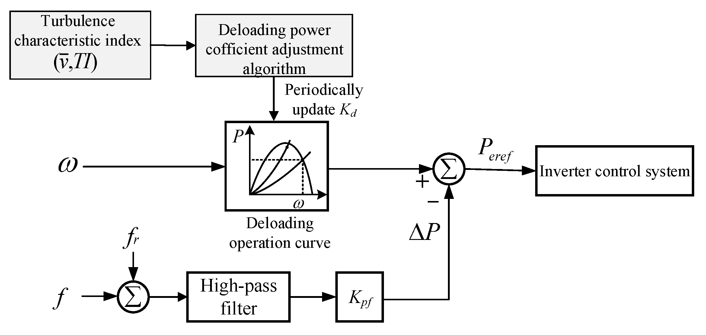
Therefore, further study has been conducted based on the author’s previous research in this paper to obtain an improved OSD control. The main contributions of this paper are as follows:
the influence mechanism of turbulent wind speed on the OSD control is analyzed;
the relationship between the reserve capacity of OSD control and deloading power coefficient under turbulent wind speed is analyzed, and the quantitative relationship between the turbulence characteristics and the deloading power coefficient is obtained;
based on the relationships above, the range of the deloading power coefficient of the OSD control is obtained, and a reasonable algorithm for setting the coefficient is designed, therefore the OSD control is improved to respond to turbulence characteristics.
Through simulations and experiments based on the experimental platform, it is verified that the improved strategy can effectively reserve enough power for frequency regulation. Compared with existing methods, the improved strategy has a better frequency regulation effect and rotor speed performance.
3. Analysis of Difficulties and Mechanism of OSD Control under Turbulent Wind Speed
Wind is caused by atmospheric movement. Due to the complex surface topography and the change in air temperature, pressure, or humidity, the atmosphere’s movement is a random and turbulent motion, which makes the wind speed fluctuate constantly, and these are the causes of turbulence. Therefore, these factors will influence the values of wind speed v, as well as the air density ρ; the wind power Pm will also be influenced according to Equation (1). It can be seen that wind speed fluctuates constantly, this is one cause of frequency deviation; therefore, wind speed fluctuation should be addressed to guarantee the stable operation of the system.
Under constant wind speed, when the OSD control is used, the wind turbine can work stably at the deloading operating point and provide the reserve capacity stably. While under turbulent wind speed, due to the fluctuation of wind speed and the influence of moment of inertia, the wind turbine cannot work at the deloading operating point in time and provide stable reserve capacity. In addition, it will even reduce the reserve capacity and weaken the frequency regulation effect. Therefore, the control strategies based on constant wind speed or steady-state will have new problems.
The example shown in
Figure 3 shows that the system response of turbulent wind speed is different from that of constant wind speed with the same control parameters, the difference in dynamic performance and the influence of wind turbulence on the control are also verified.
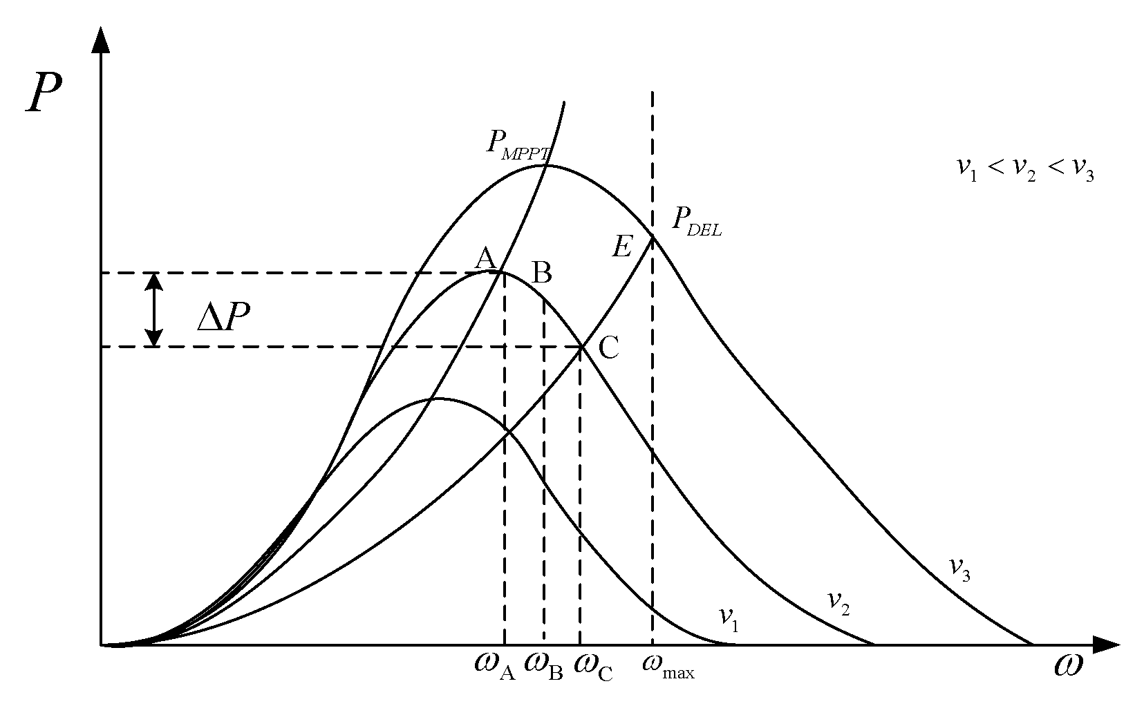
It is found that the slope of the optimal power curve is reduced when the wind turbine uses OSD control (such as
Pdel shown in
Figure 2). Therefore, the difference between mechanical torque and electromagnetic torque is increased, which improves the performance of the wind power system in tracking the maximum power point under turbulent wind speed [
12], then the available reserve capacity will be reduced due to the improved wind energy capture efficiency. That means
Kd will change the dynamic performance of the wind power system, and then affect the reserve capacity and frequency regulation effect of the wind power system. The elaboration is shown as follows.
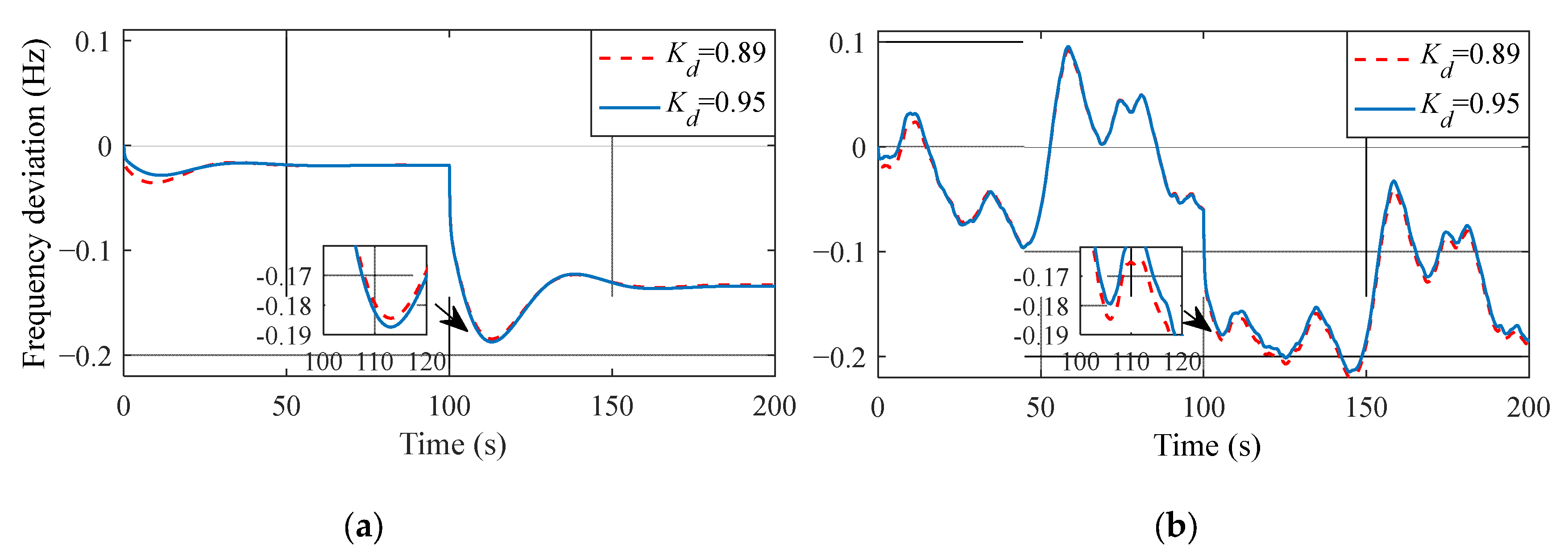
Under constant wind speed, when the load suddenly increases at 100 s, the smaller the
is, the better the lowest frequency and then the better the frequency regulation effect will be, as shown in
Figure 3a. However, under turbulent wind speed, the result is just the opposite. The smaller the
is, the more severe the frequency falls, as shown in
Figure 3b.
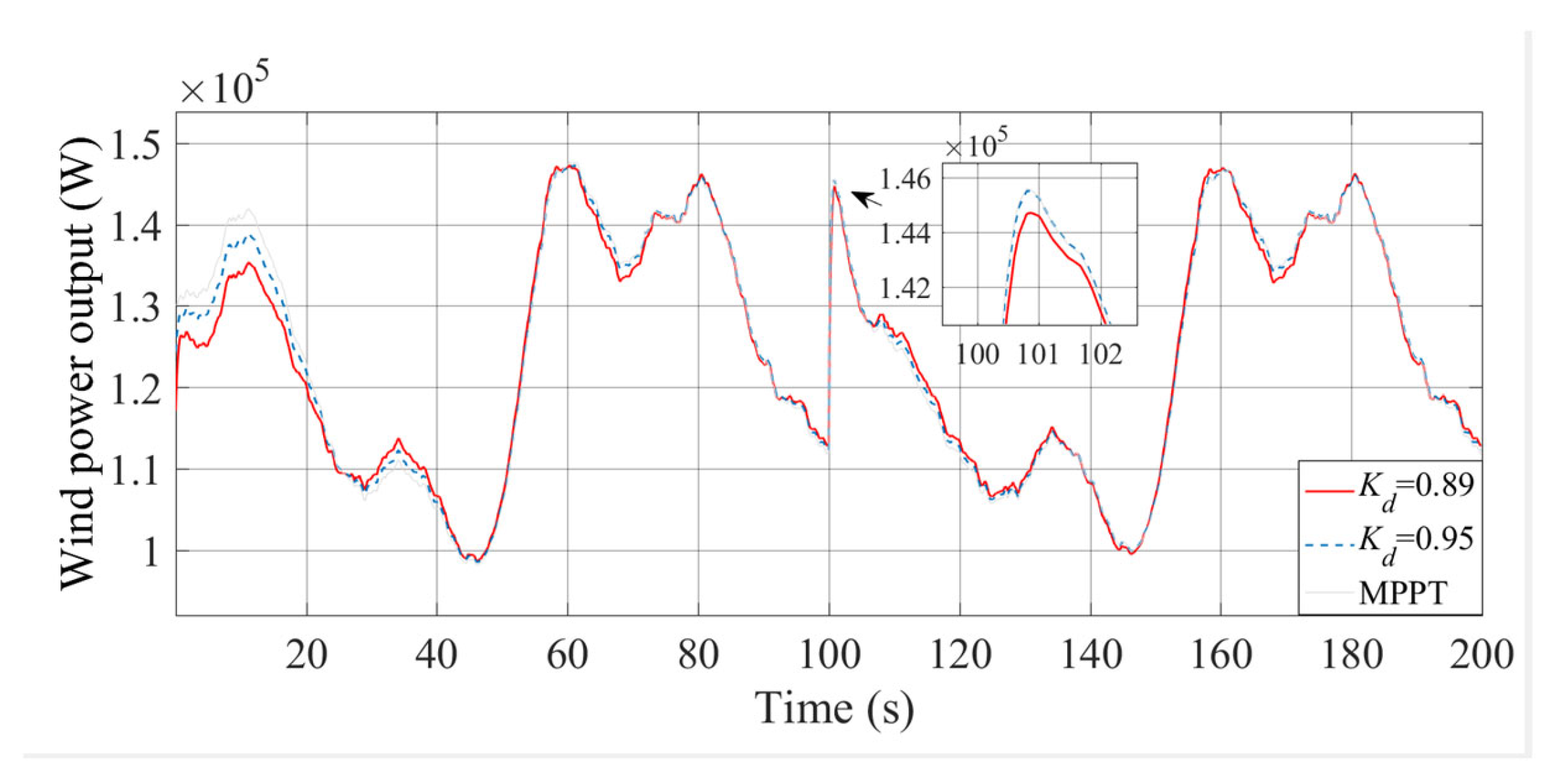
Figure 4 shows the wind power output of the example shown in
Figure 3b. It can be seen that when load suddenly increases at 100s, the wind power with
of 0.89 is lower than that of 0.95 and the MPPT control.
Table 2 shows the average wind energy capture efficiency, the average frequency deviation and the reserve capacity factor [
21] under different strategies in
Figure 4. The average wind energy capture efficiency is defined by Equation (5), and the average frequency deviation is defined by Equation (6).
The reserve capacity factor represents the reserve capacity of wind turbines. The higher the value, the lager the reserve capacity. The definition can be given by Equation (7) of
Section 4.
where
is the power coefficient of the
ith sample,
n is the total number of samples.
where Δ
fi is the frequency deviation of the
ith sample,
n is the total number of samples, and the sampling period is 0.04 s.
It can be known from
Table 2 that when
is 0.89, the wind energy capture efficiency is the highest, but the reserve capacity factor is the smallest, so it is difficult to provide enough power to support frequency adjustment in case of load fluctuation. The wind energy capture efficiency of MPPT control is the lowest, while the reserve capacity factor is the highest. It is verified that under turbulent wind speed, it will have a worse control effect with the same
as the constant wind speed.
So, the OSD control under turbulent wind speed does not play its function of reserving power for frequency regulation, and the frequency regulation effect is even worse than that of MPPT control without reserving power, which is the difficulty of OSD control applied to turbulent wind speed.
5. Example Analysis
5.1. Simulation Analysis
In order to verify the superiority and effectiveness of the improved strategy in this paper, the method with fixed
(
is 0.9), the variable deloading power coefficient method proposed in [
23] (hereafter referred to as variable
) and the improved strategy in this paper are compared.
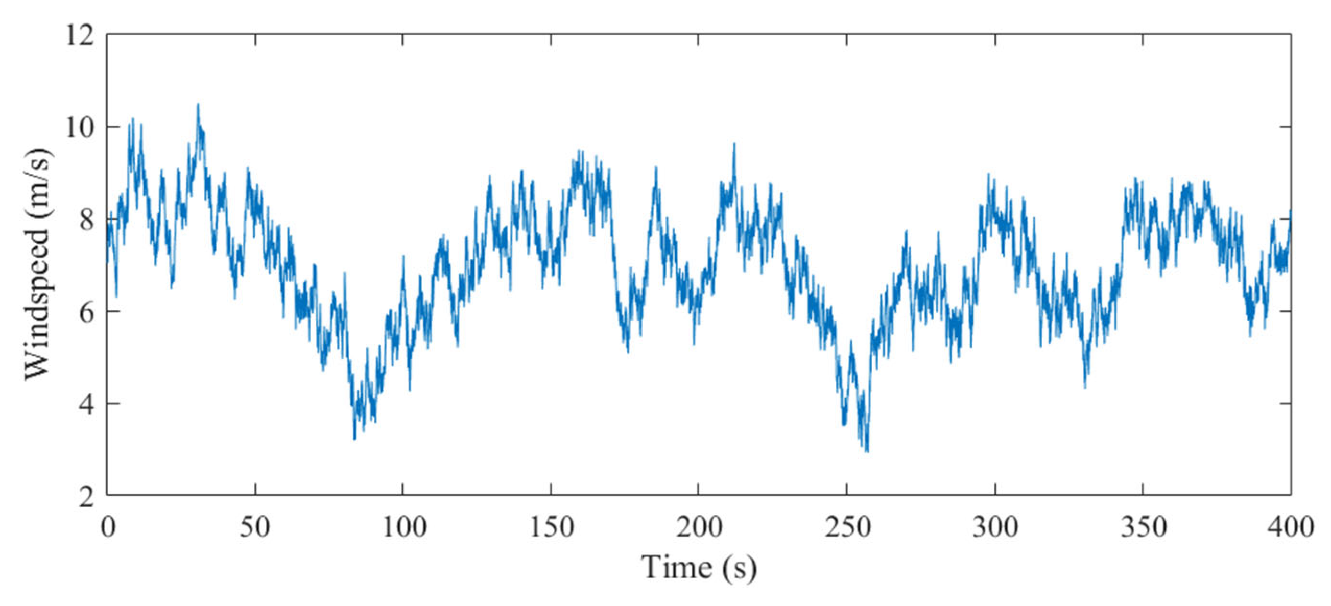
A turbulent wind speed with average wind speed of 8 m/s and turbulence intensity of level A is used for simulation, and the load suddenly increases at 100 s.
The simulation parameters are shown in
Table 3. The rated power of the wind power system in the simulation is 0.6 MW, and the rated wind speed is 12 m/s. The wind speed used in this paper mainly runs between 5 m/s and 12 m/s. The wind speed profile used in simulation is shown in
Figure 10.
- 2.
Analysis of simulation results
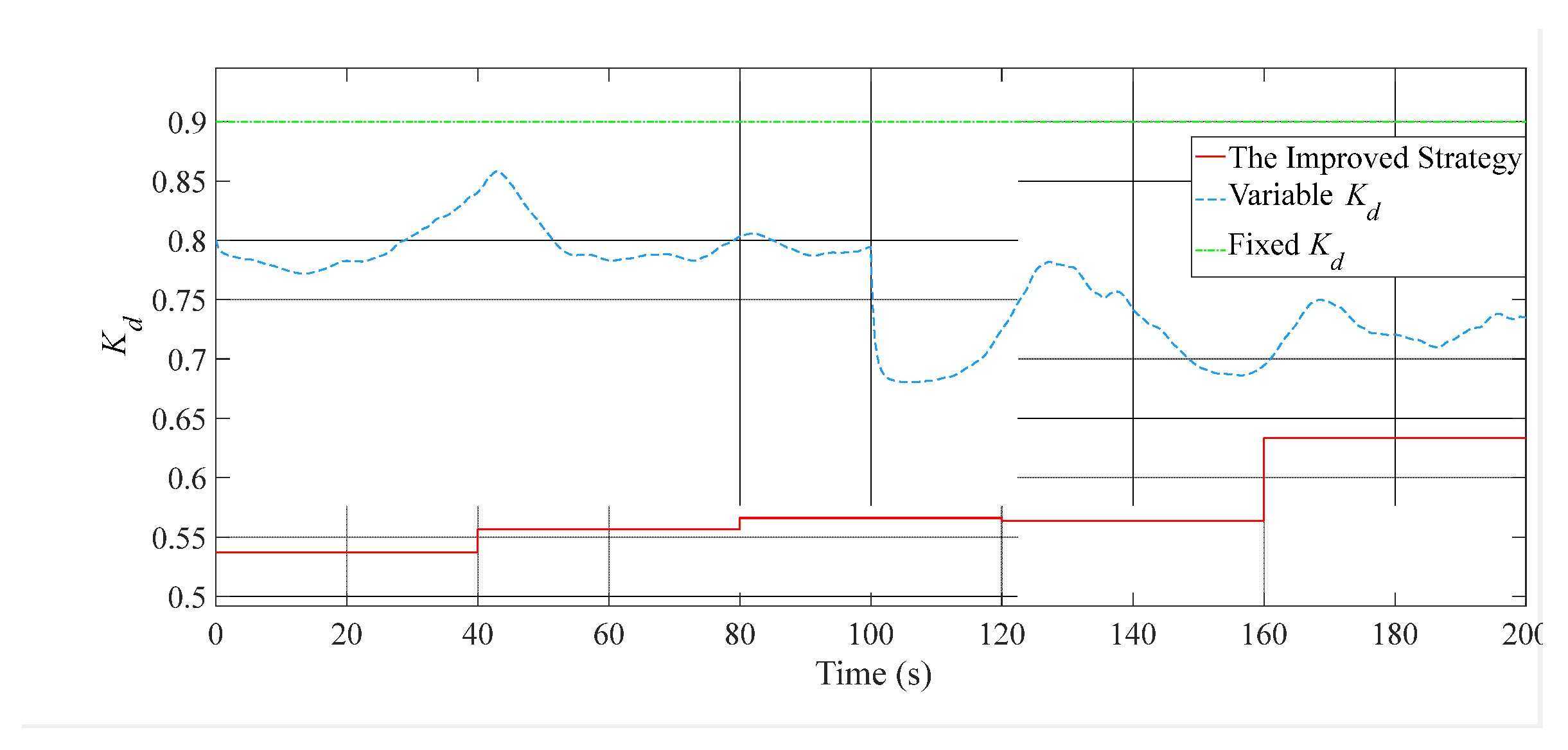
Figure 11,
Figure 12,
Figure 13,
Figure 14 and
Figure 15, respectively, show the frequency deviation of the grid, wind power output, the operation curve of wind turbine before and after load change (95 s–120 s), and the
of different strategies.
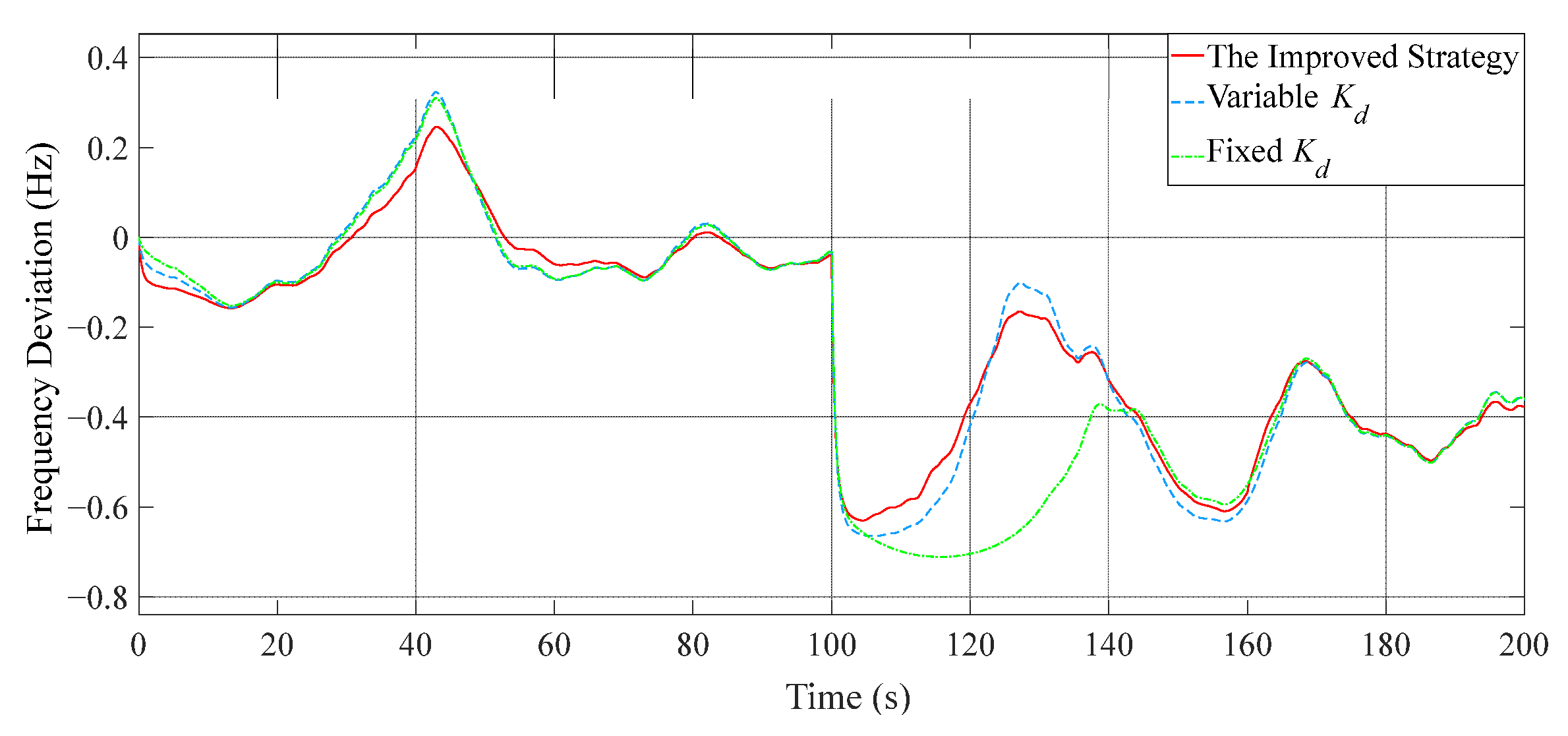
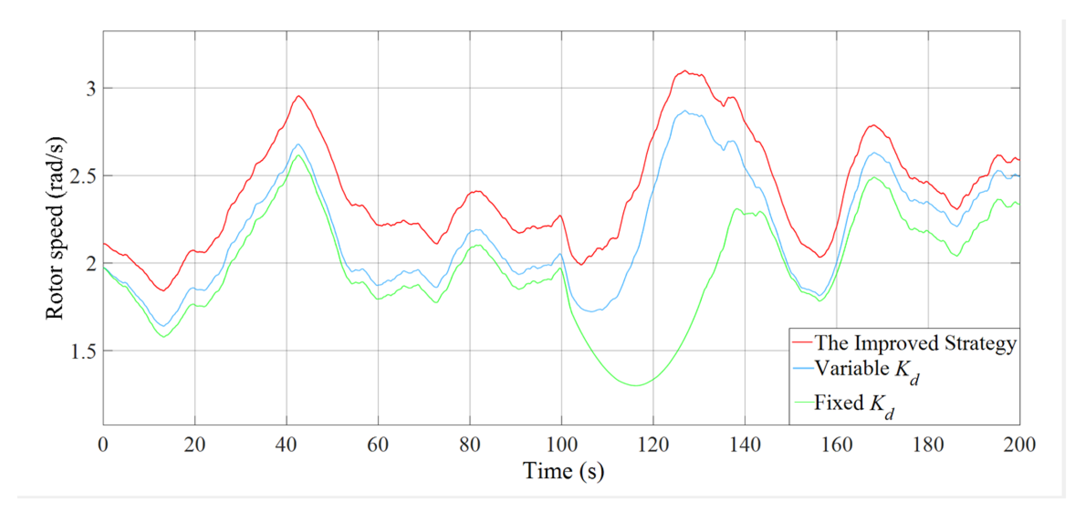
It can be seen from
Figure 11 that after sudden load increasing at 100 s, the frequency of the three strategies decreases, but the decline of the improved strategy in this paper is significantly less than the other two strategies. And when the frequency support using the reserve capacity is completed, the improved strategy in this paper can recover the tracking of wind speed more quickly. However, the method with variable
and the one with fixed
have a longer recovery process due to the large drop in rotor speed. It can also be seen from
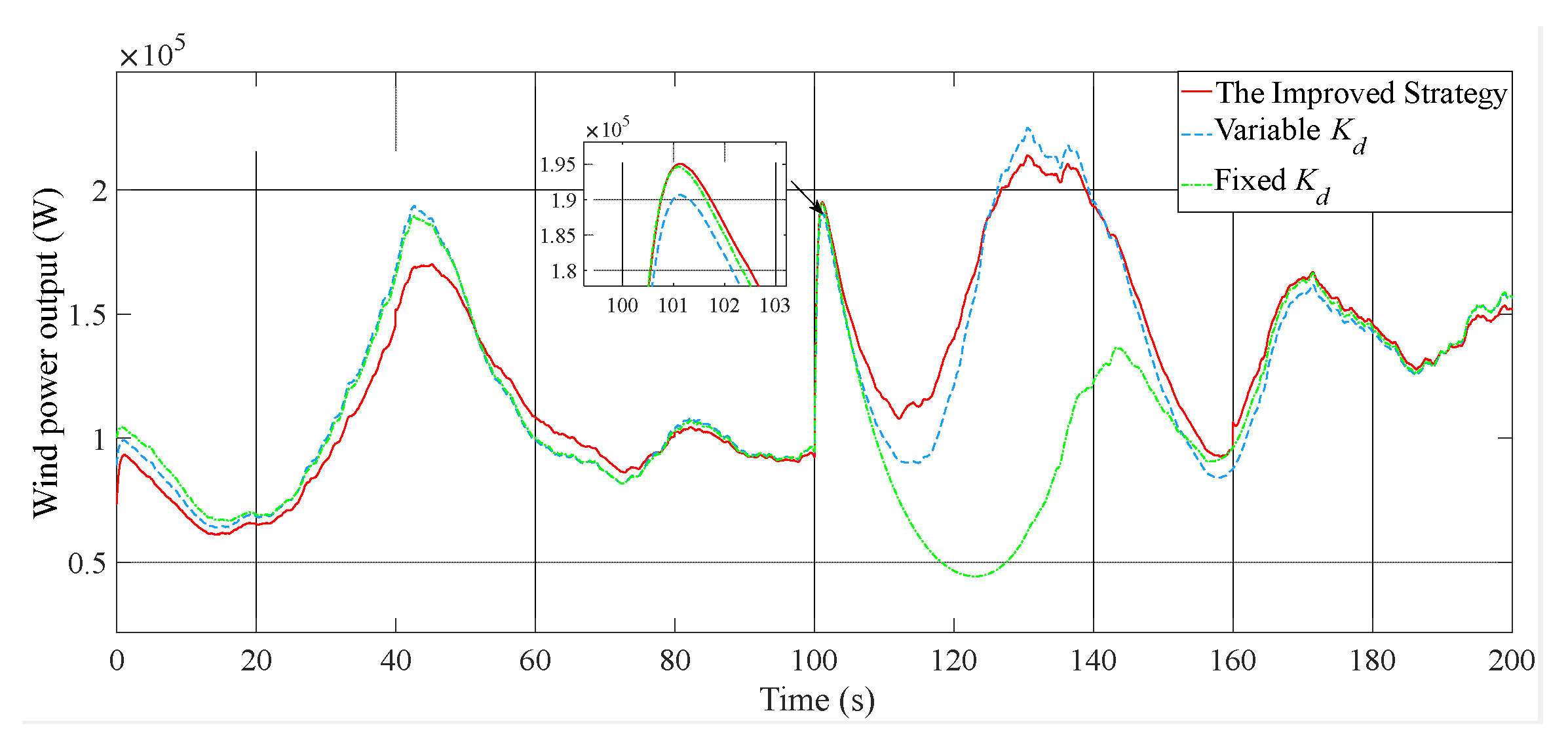
Figure 12 that the improved strategy in this paper provides greater output power when the load suddenly increases at 100 s.
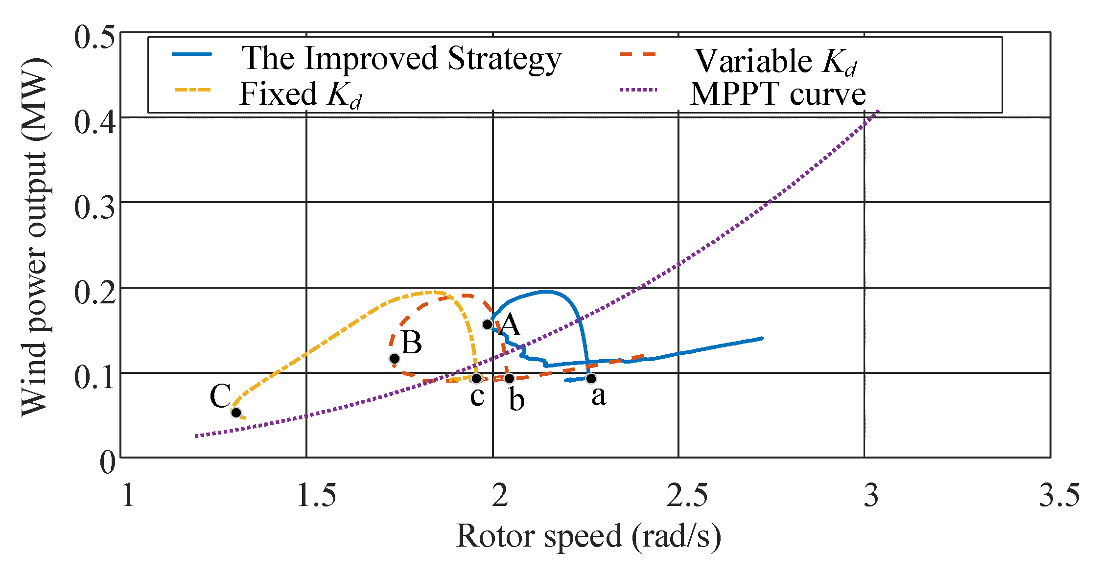
It can be seen from
Figure 14 that a, b and c are the operating points of the three strategies at 100 s, A, B and C are the times when the rotor speed stops falling and begins to recover. When the load suddenly increases at 100 s, the operating points of the three strategies rise rapidly. After a short period of power support, the speed starts to drop, and the operating point moves to the left. It can be seen that the rotor speed drop of the improved strategy in this paper is obviously smaller than that of the other two strategies, and it can recover faster. However, the rotor speed of the fixed
method has a long time drop, which leads to continuous low output power that is not conducive to the frequency adjustment of the system. At the same time, the rotor stall problem is prone to occur, and there is a risk of making the wind power system go out of service.
Table 4 shows the average frequency deviation of the three strategies and the improvement of the improved strategy compared with other strategies.
The average wind energy capture efficiency of the three strategies is compared in
Table 5.
The wind energy capture efficiency of the improved strategy is higher than that of the method with fixed Kd and lower than that of variable Kd. When the load fluctuation occurs in the control with fixed Kd, the participation of the wind power system in frequency regulation leads to a serious drop in the rotor speed, so the wind energy capture efficiency is low. However, the rotor speed of the improved strategy in this paper is at a high level, so there is no serious rotor speed drop.
Due to the lower Kd than that of variable Kd, the wind energy capture efficiency of the improved strategy in this paper is lower than that of variable Kd, but the improved strategy obtains a better frequency regulation effect.
Wind energy capture efficiency and frequency regulation are always in conflict because the wind power system will give up tracking the maximum power point when it is participating in frequency regulation. The performance of frequency regulation becomes a more important goal. In the standard of GB/T 19963-2011 “Technical Regulations for Wind Farm Access to Power System”, it is required that wind power systems should provide power to support the power system frequency. Additionally, the proportion of wind power systems in the power system will be larger and larger and the traditional synchronous generator will reduce, so wind power systems will play an important role in frequency regulation. In this case, the improved strategy is reasonable and valuable.
From the above analysis, it can be seen that the improved strategy in this paper can provide better reserve capacity, and the frequency regulation effect is much better. Compared with the control with fixed , the frequency deviation can be increased by 19.28%, and the rotor speed can be well maintained to avoid the secondary frequency drop caused by rotor stall and rotor speed drop.
5.2. Experimental Analysis
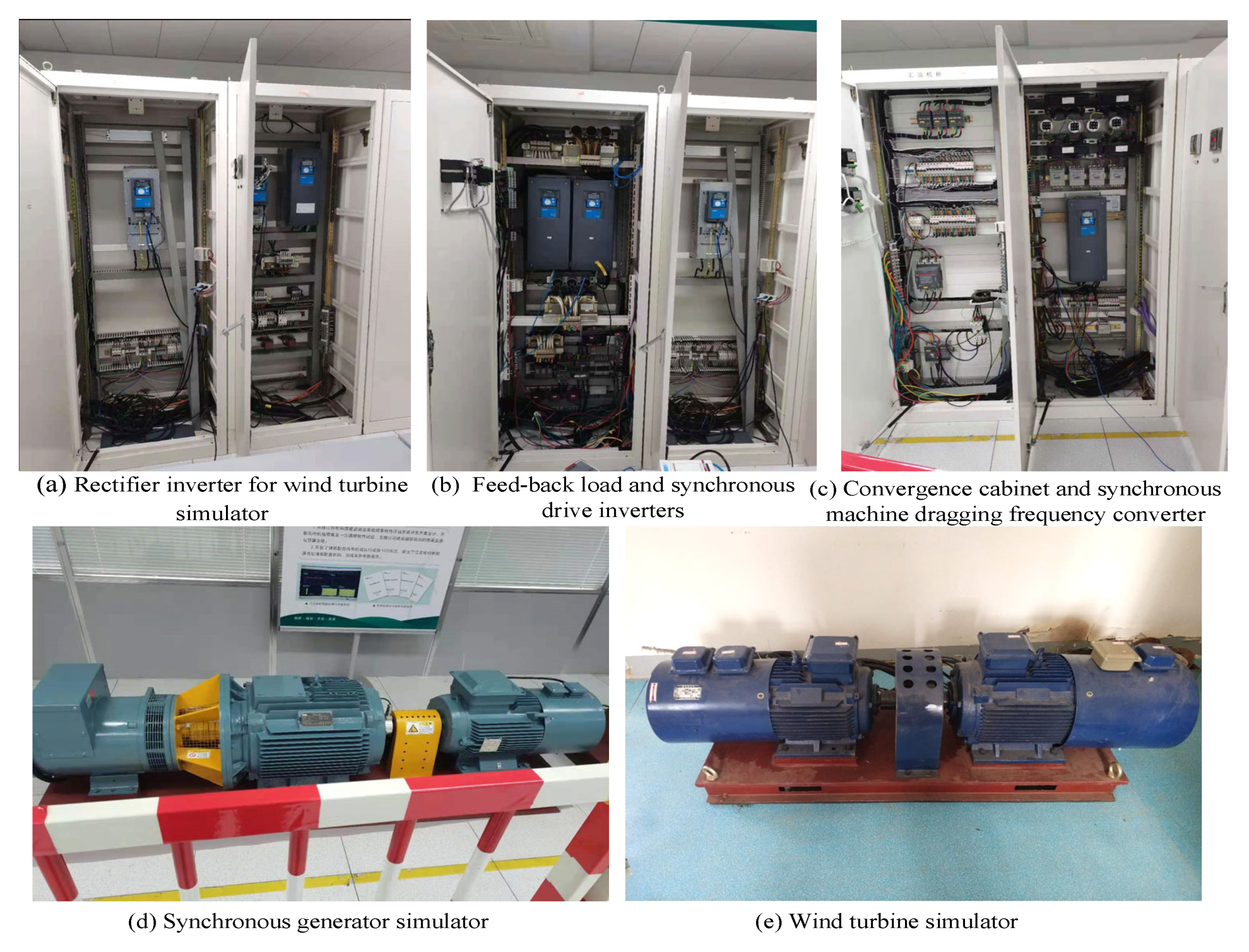
In order to verify the effectiveness of the improved strategy, it is verified on the frequency regulation experimental platform with a wind power system. As shown in
Figure 16, the experimental platform consists of seven parts: a synchronous generator simulator, wind turbine simulator, rectifier inverter for wind turbine simulator, synchronous drive inverters, synchronous machine dragging frequency converter, convergence cabinet and feed-back load. The experimental platform can simulate the frequency response of the power grid with wind turbines.
Table 6 gives the main parameters of the experimental platform. Through the power scaling and inertia compensation algorithm [
24], the wind turbine simulator in the experimental platform realizes the dynamic characteristics of the large capacity, large inertia wind power system, the frequency response characteristics of the actual power grid on the small capacity and low inertia experimental platform, which can be used to verify the control performance of the primary frequency regulation control strategy of the wind turbine. The wind turbine parameters simulated by the wind turbine simulator are the same as those of the simulation model.
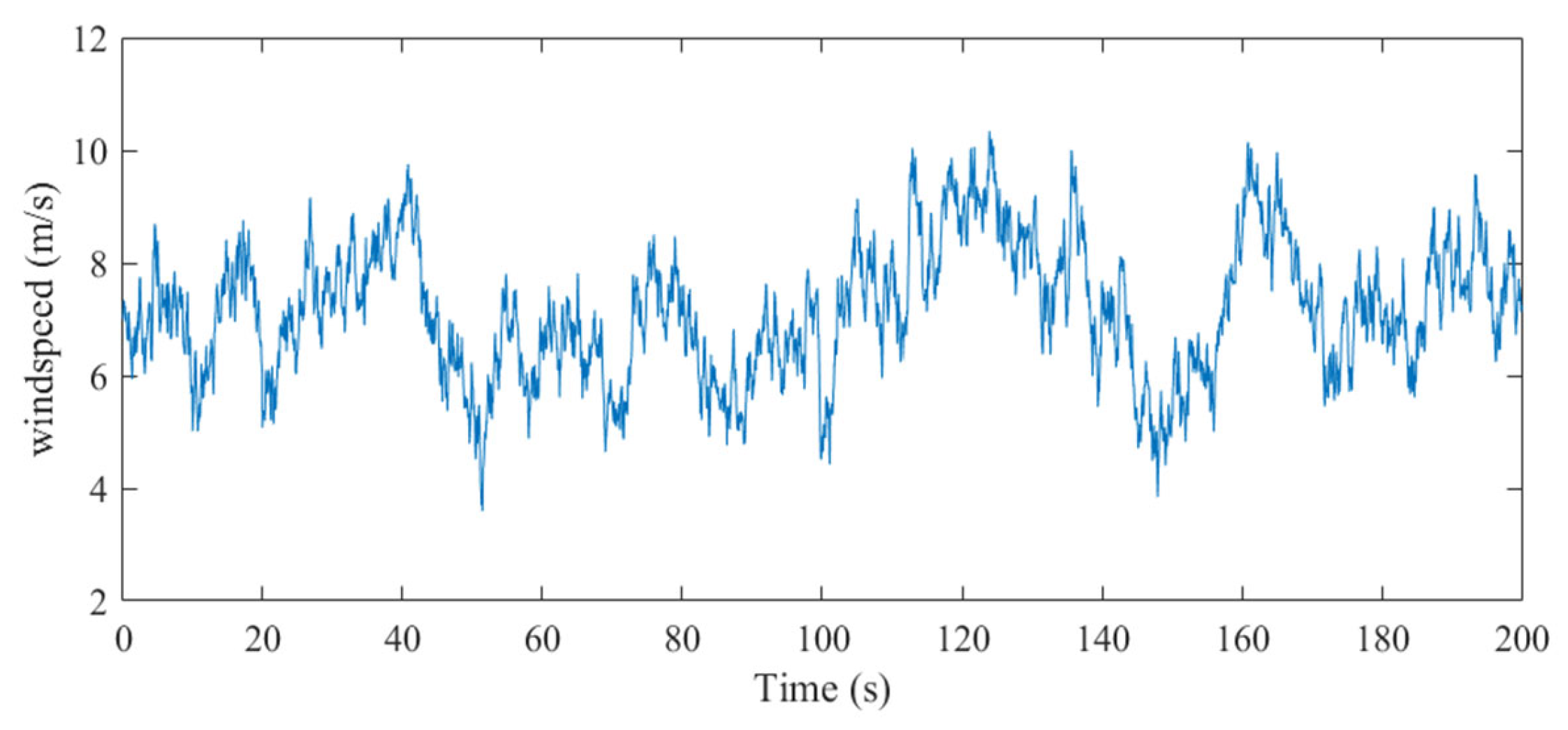
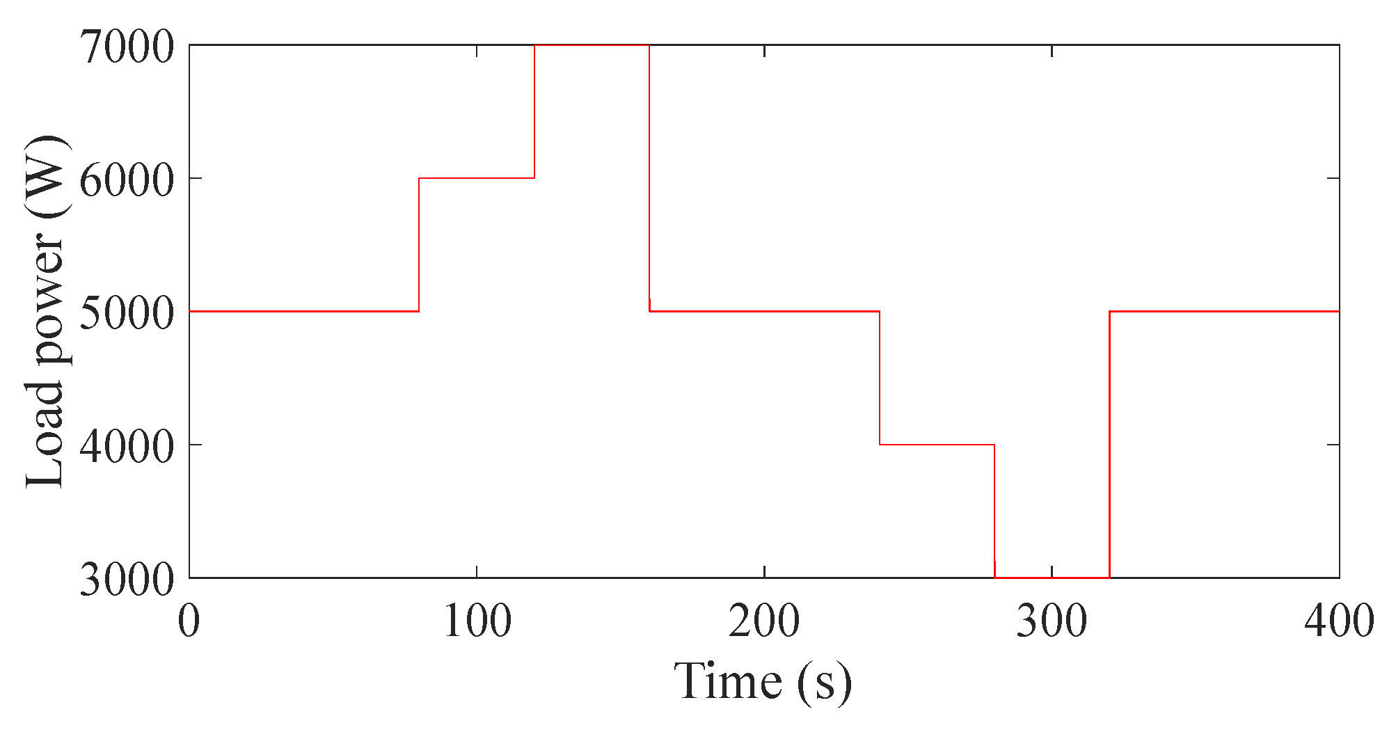
A turbulent wind sequence with an average wind speed of 8 m/s and turbulence intensity level A is adopted for experimental analysis which is shown in
Figure 17, and the load is set as in
Figure 18. The improved strategy and the traditional deloading control with fixed
(
is 0.9) are compared by the experiment. The experimental results are shown in
Figure 19,
Figure 20 and
Figure 21.
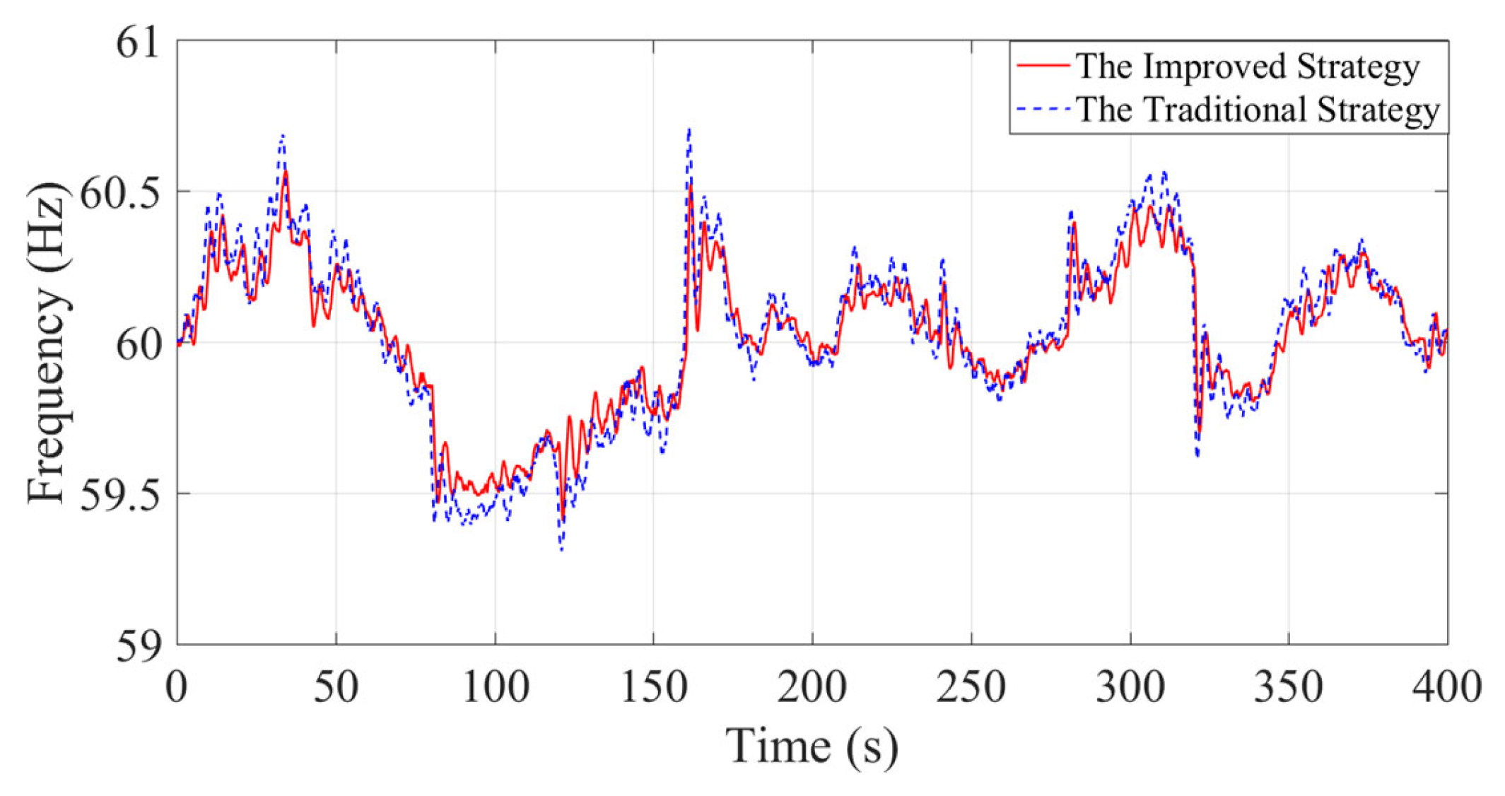
It can be seen from
Figure 19 that the frequency fluctuation of the improved strategy in this paper is significantly smaller than that of the traditional strategy in the case of sudden load changes, and the frequency deviation of the improved strategy has increased by 8.3%.
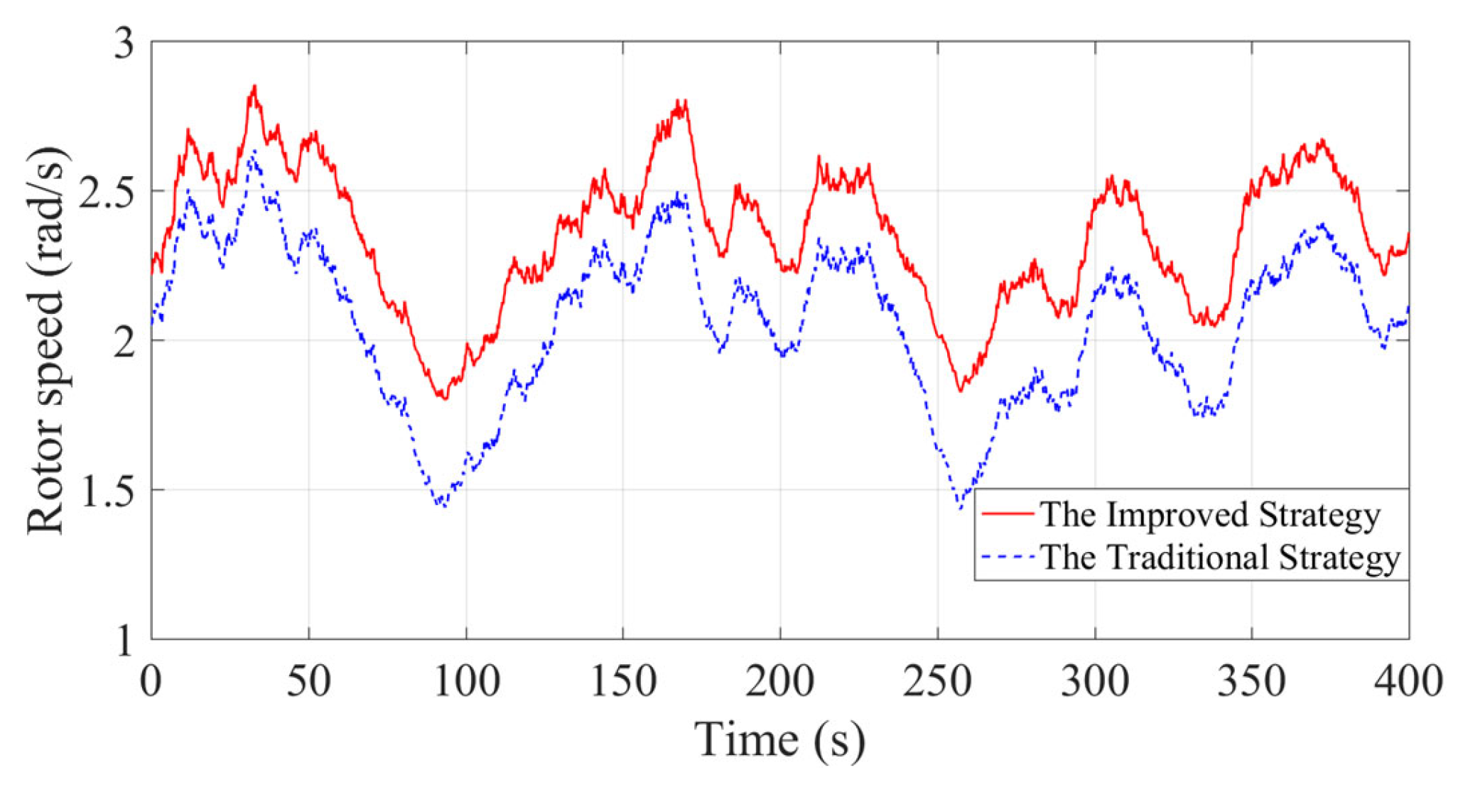
Figure 20 shows the rotor speed of the wind turbine. Compared with the traditional strategy, the rotor speed of the improved strategy in this paper is at a higher level, and the rotor speed fluctuation is small, which can effectively mitigate the fatigue damage of the rotor and improve the stall problem caused by the low rotor speed.
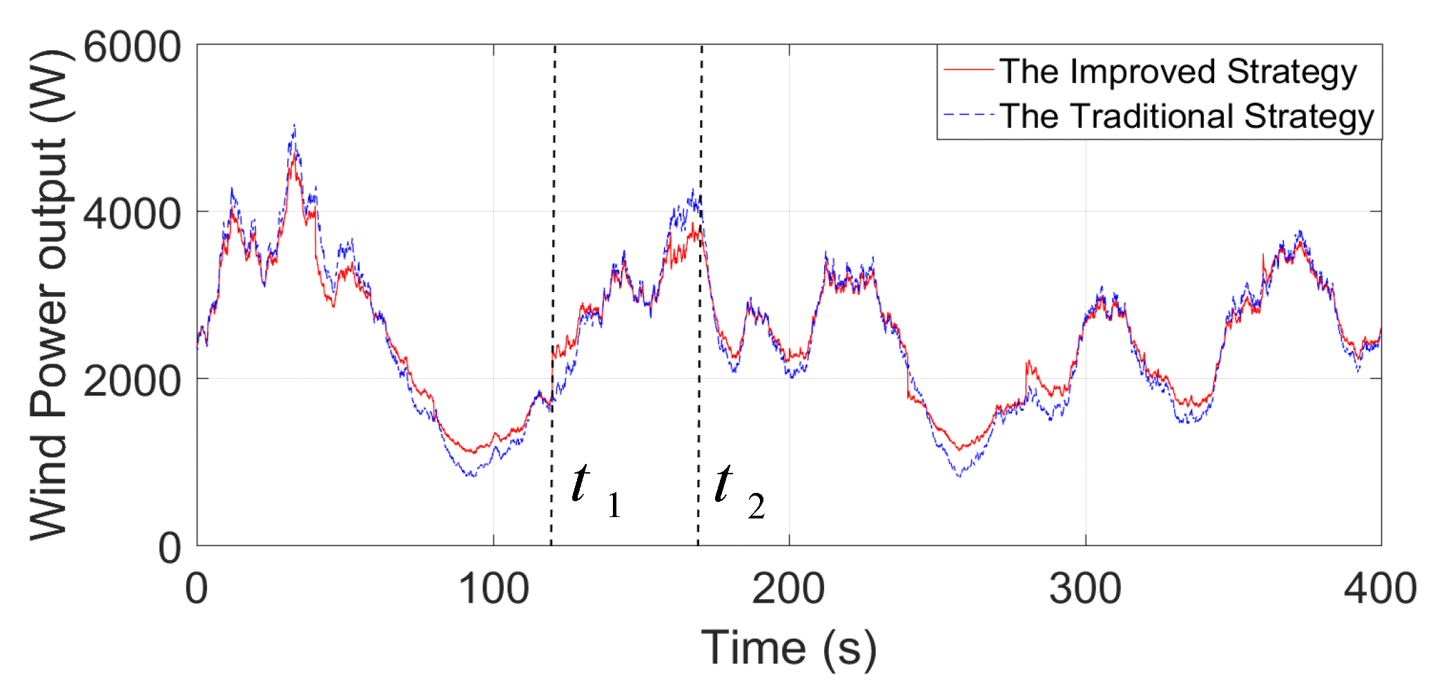
The wind power output in
Figure 21 shows that the power fluctuation of the improved strategy in this paper is smaller than that of the traditional strategy, which also improves the frequency stability to a certain extent. In addition, wind power can be increased or decreased faster and better in the case of sudden load changes. When the load suddenly increases at time
t1, the increased power of the improved strategy is higher than that of the traditional strategy. When the load suddenly decreases at time
t2, the output power of the improved strategy can better respond to frequency changes and be reduced faster.
6. Conclusions
This paper aims at improving the performance of OSD control under turbulent wind speed, proposing an improved OSD control strategy, which improves the effect of wind power participating in power grid frequency regulation under turbulent wind speed. The main contributions and conclusions of this paper are as follows.
The mechanism of poor control effect of OSD control under turbulent wind speed is revealed; the OSD control has the effect of improving the output power of wind power system, thus reducing the reserved power and weakening the frequency regulation effect.
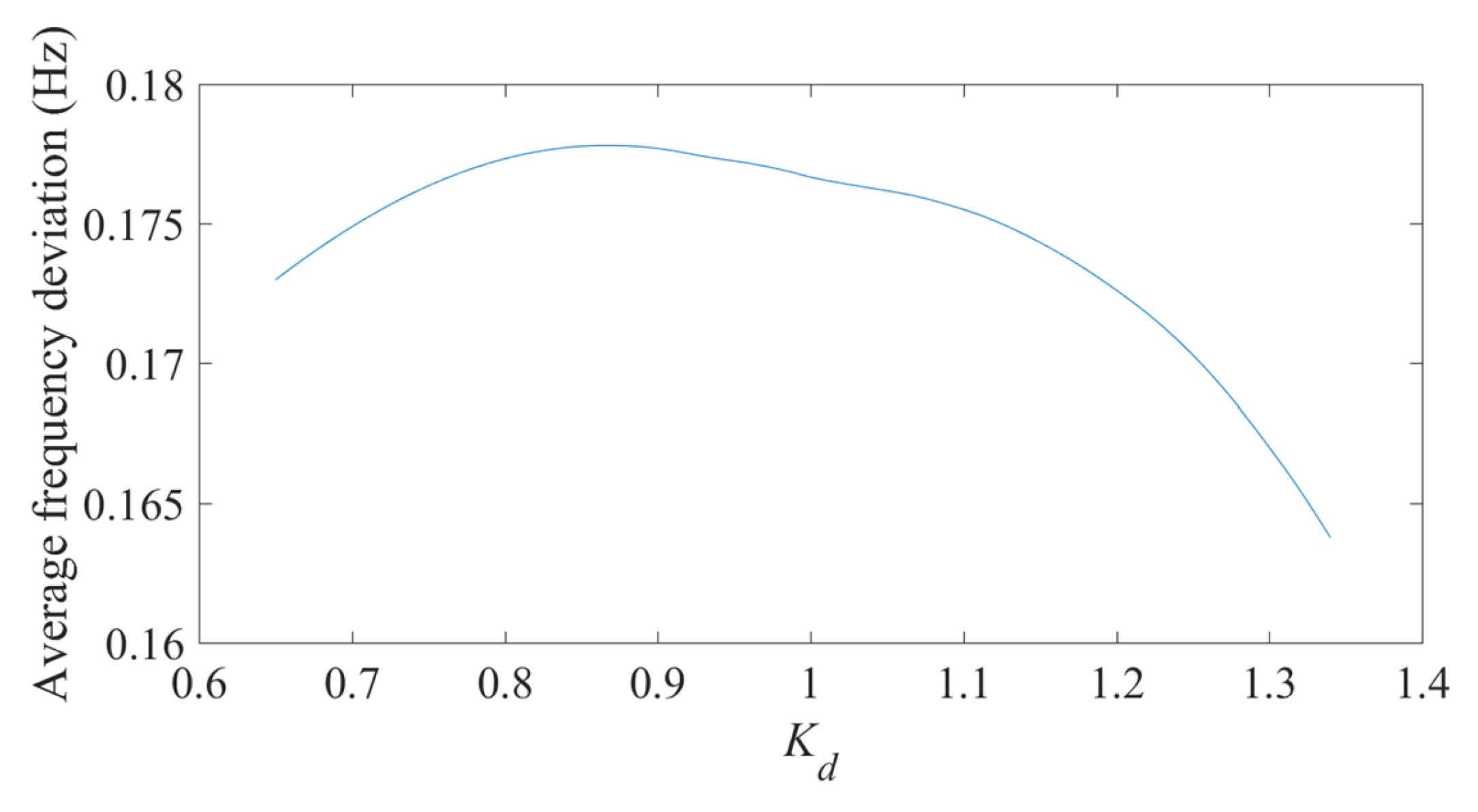
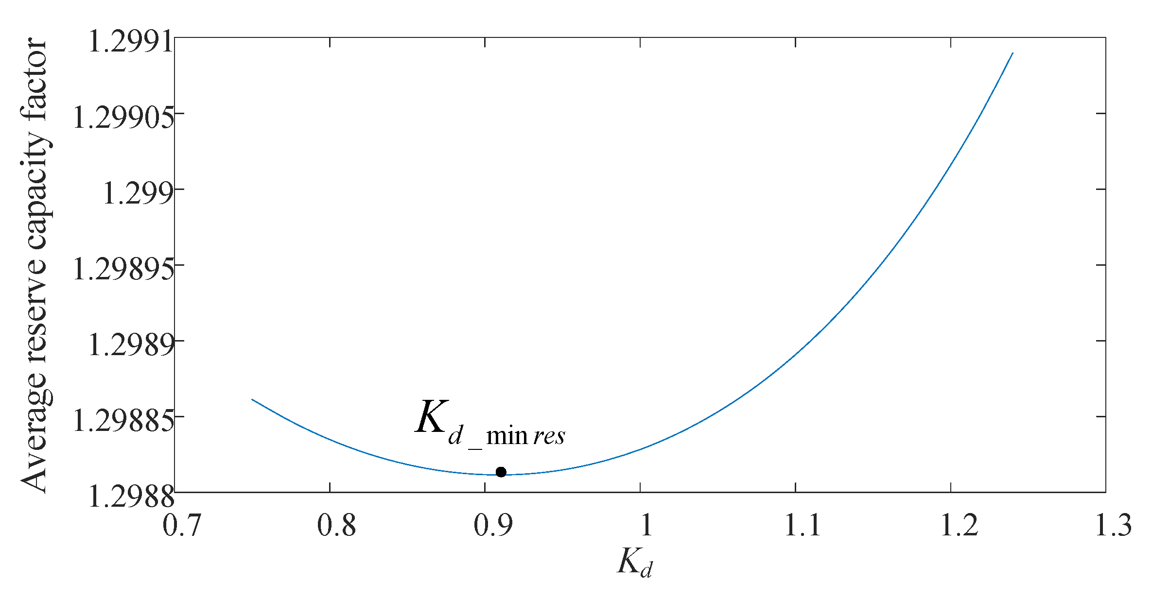
The influence of deloading power coefficient on reserve capacity and frequency deviation is analyzed. It is found that there is an extreme value that minimizes the reserve capacity of the wind power system, and the extreme value will change with the turbulence characteristics of turbulent wind speed.
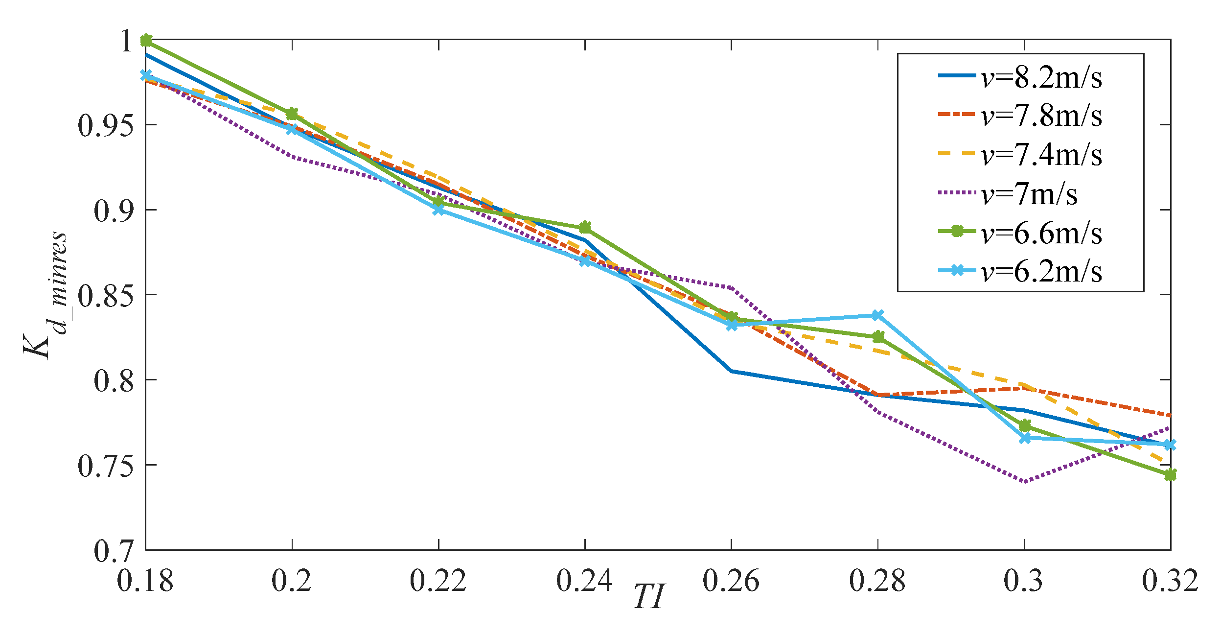
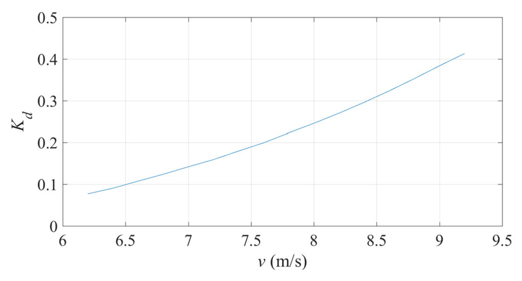
The mathematical relationship between the deloading power coefficient corresponding to the minimum reserve capacity and the turbulence characteristic index is obtained, and the reasonable range of the deloading power coefficient under different wind conditions is proposed accordingly.
An algorithm for optimizing deloading power coefficient based on turbulence characteristics is proposed, which can make wind turbines effectively respond to different wind conditions, provide reserve capacity stably and quickly, and improve the frequency regulation effect under turbulent wind speed.
Compared with the existing methods, the simulation and experimental results based on the experimental platform show that the improved control strategy proposed in this paper has better performance in decreasing frequency deviation, degree of frequency drop, expediting rotor speed recovery and avoiding the secondary frequency drop, and that the improvement in frequency deviation can reach 19.28%.


