
Optimization of the Electrochemical Discharge of Spent Li-Ion Batteries from Electric Vehicles for Direct Recycling

Abstract
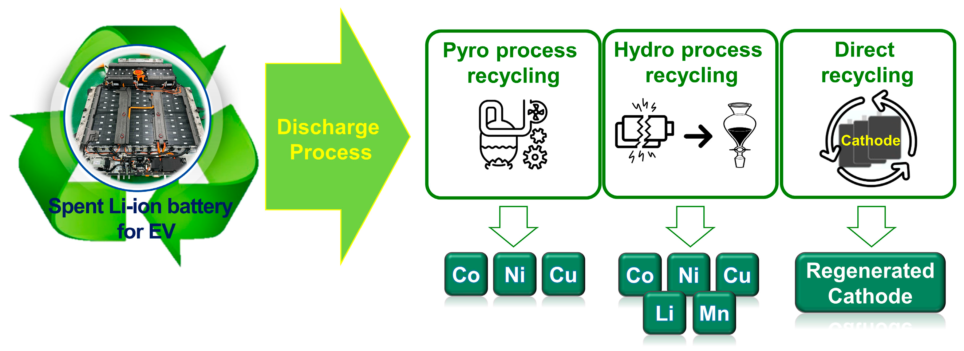
:1. Introduction
2. Experiment
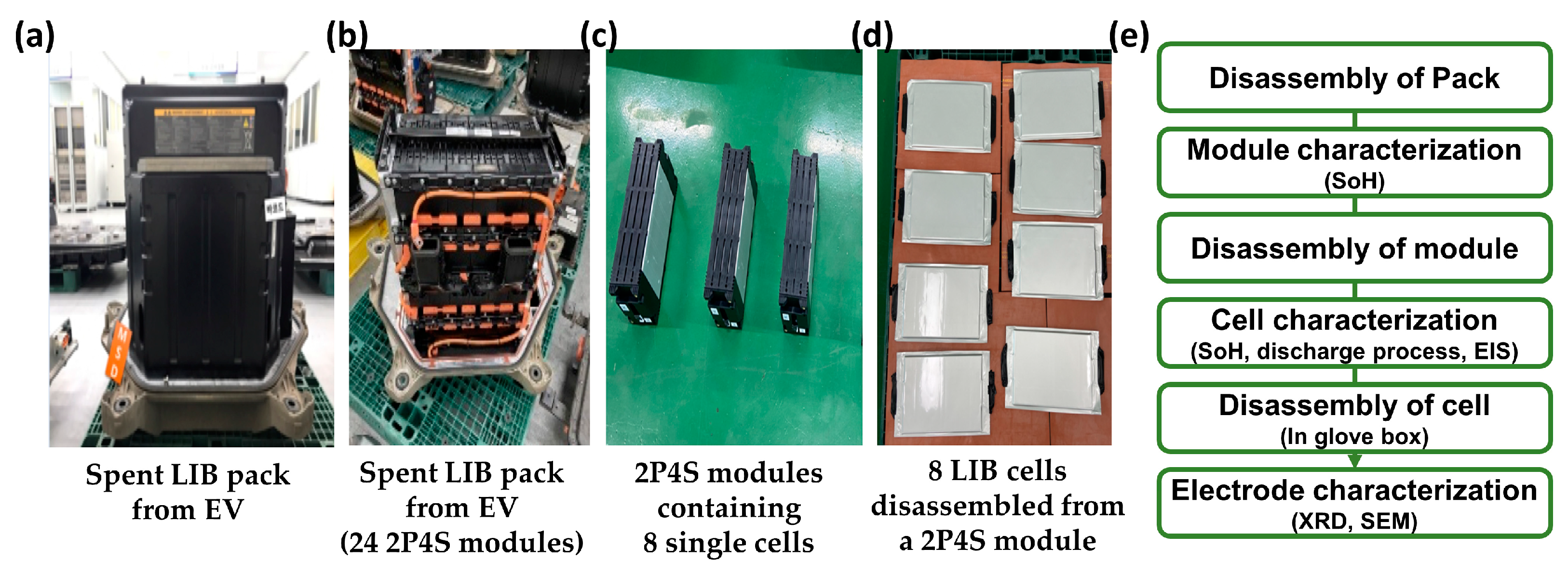
2.1. Disassembly of Spent LIB Packs from EVs
2.2. Discharge Process Using Salt Water
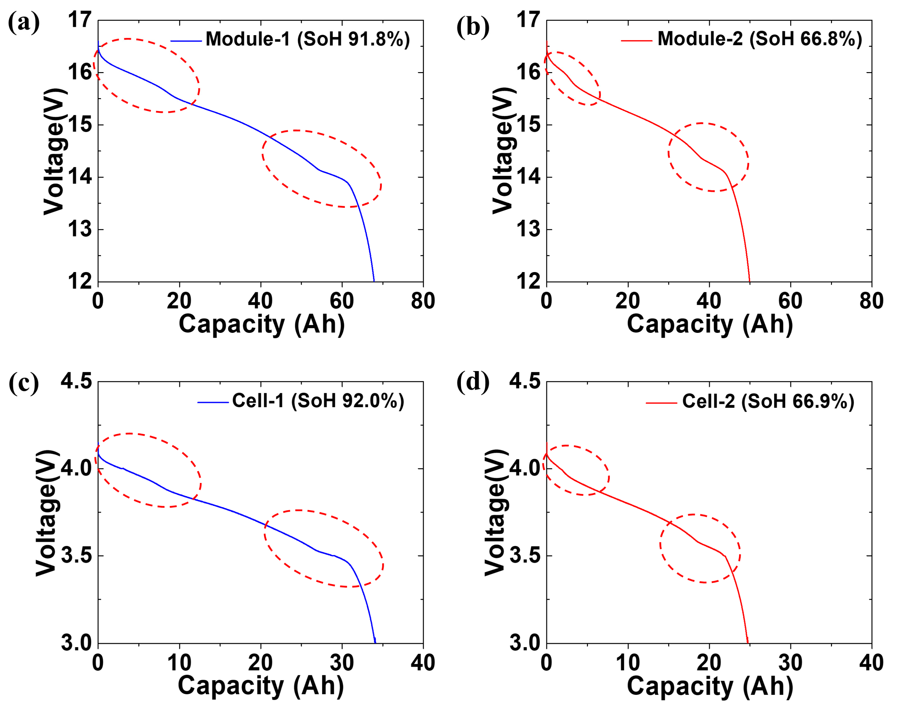
2.3. Module Characterization
2.4. Cell Characterization
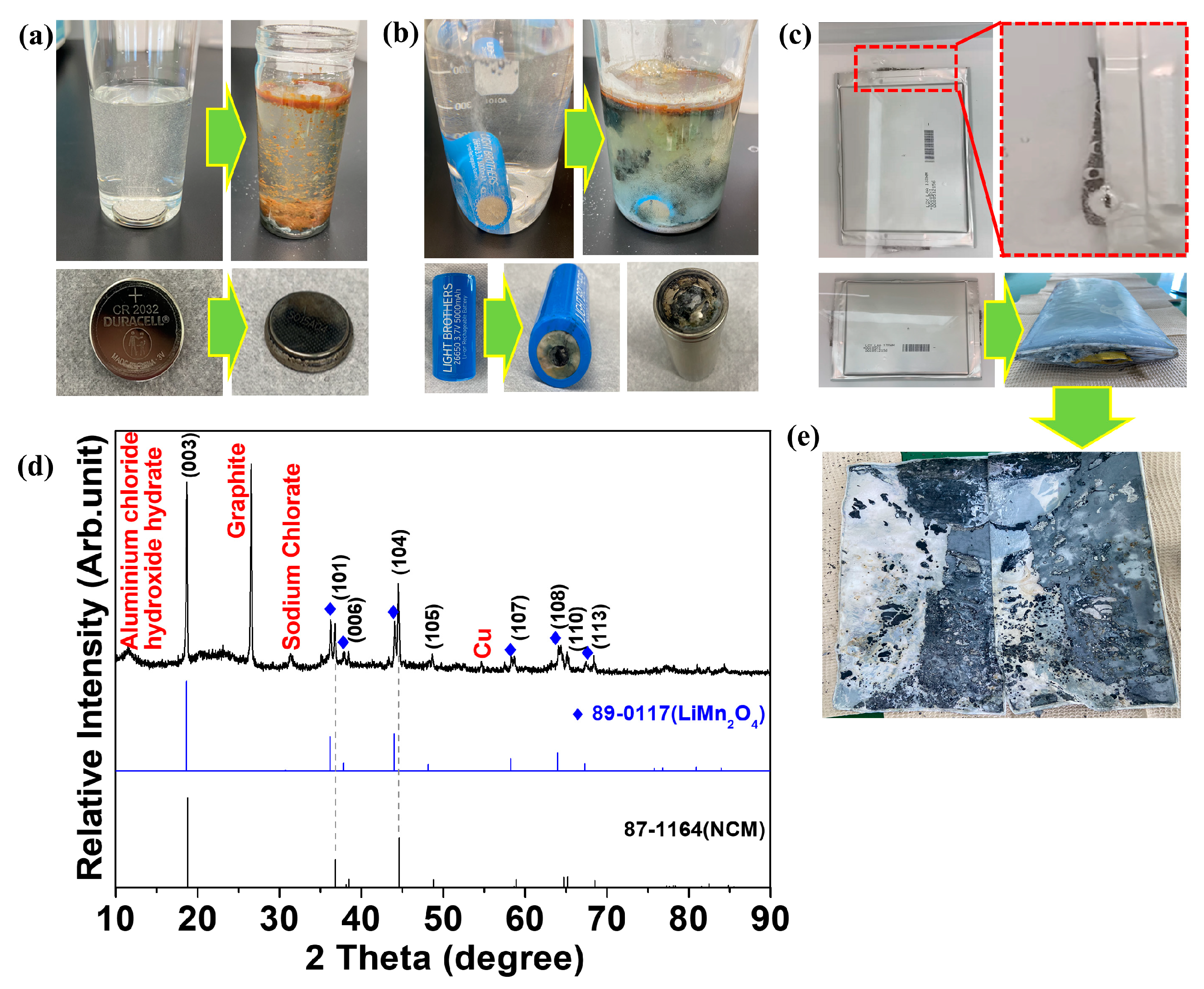
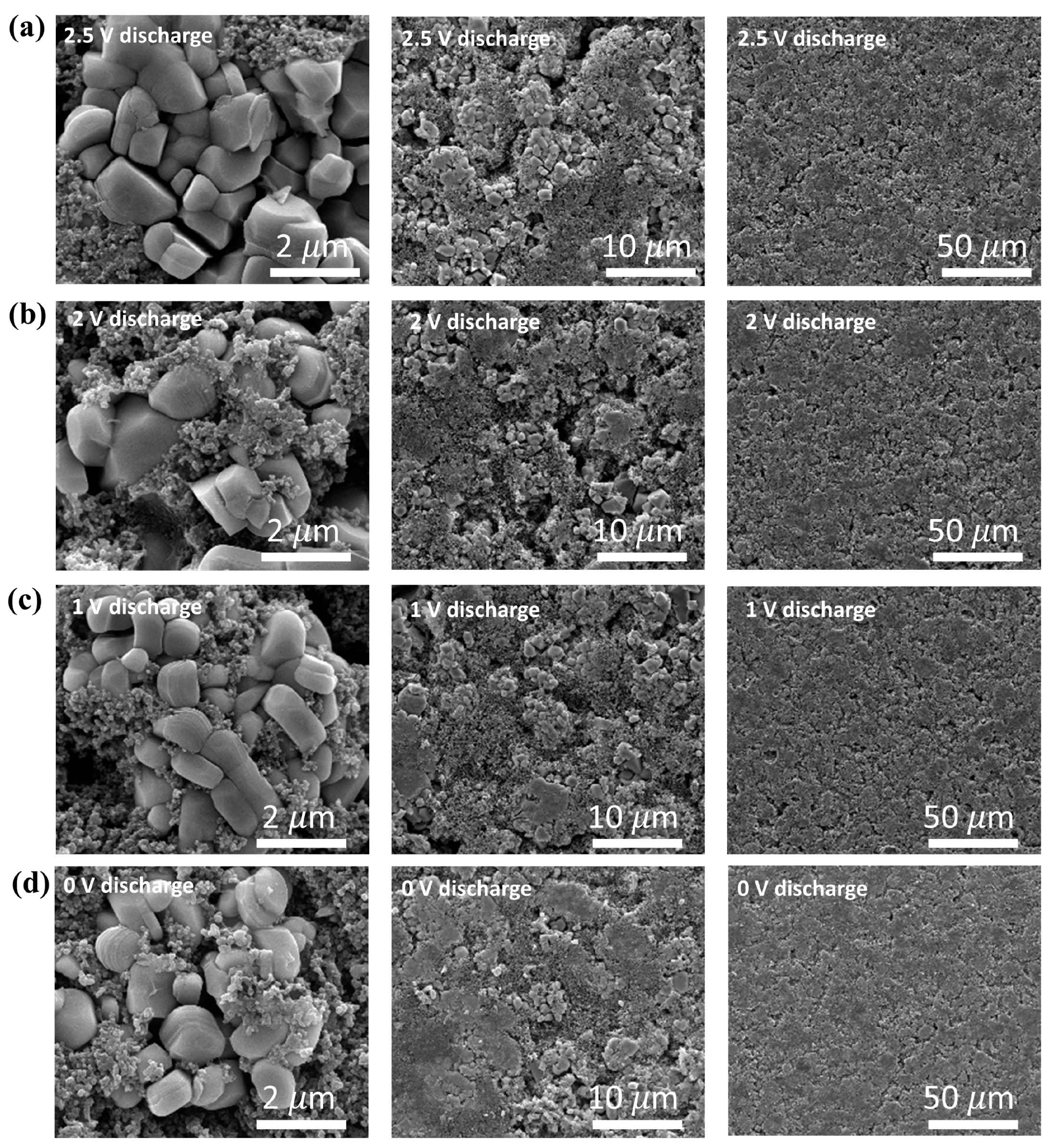
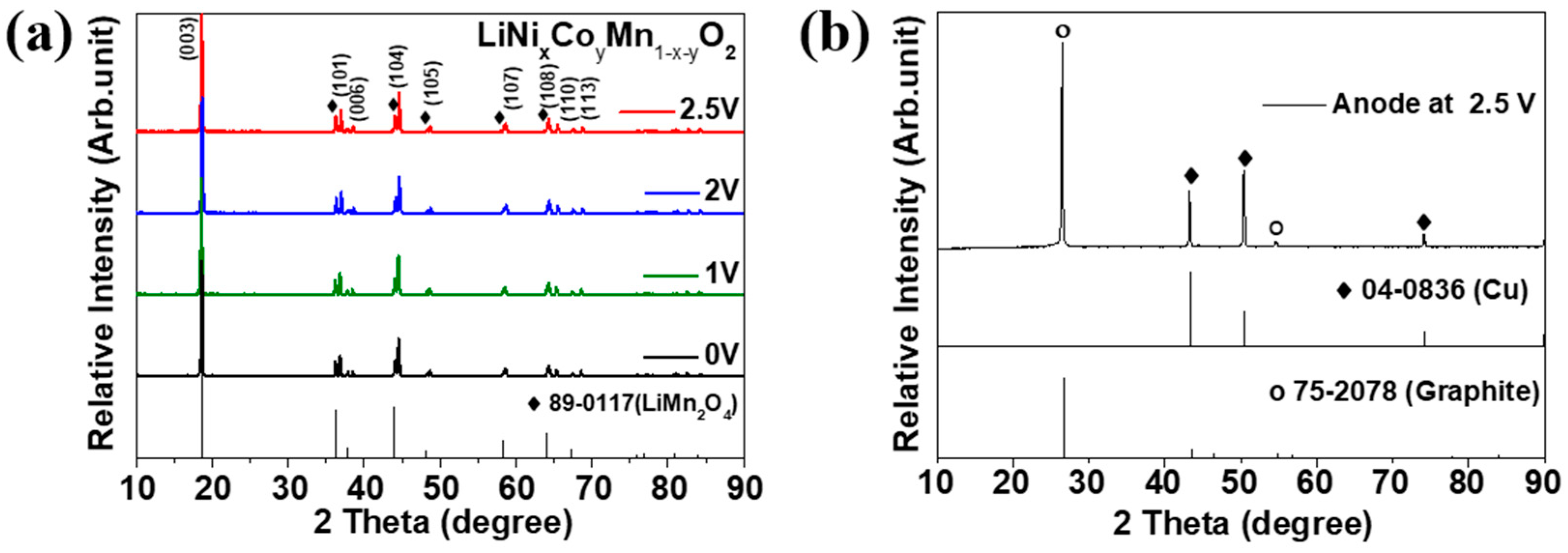
2.5. Sample Characterization after Electrochemical Discharge
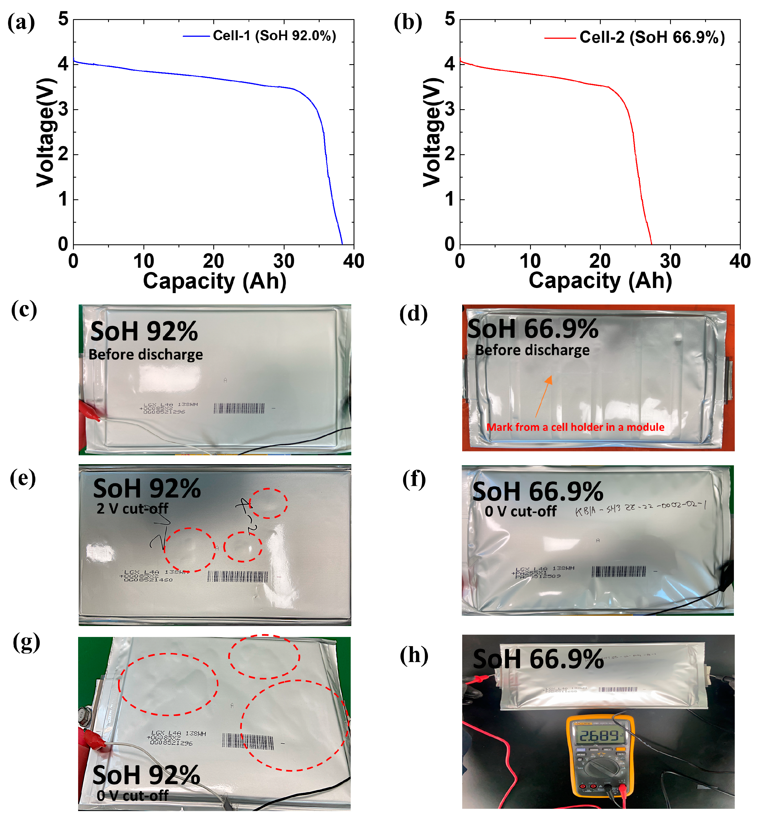
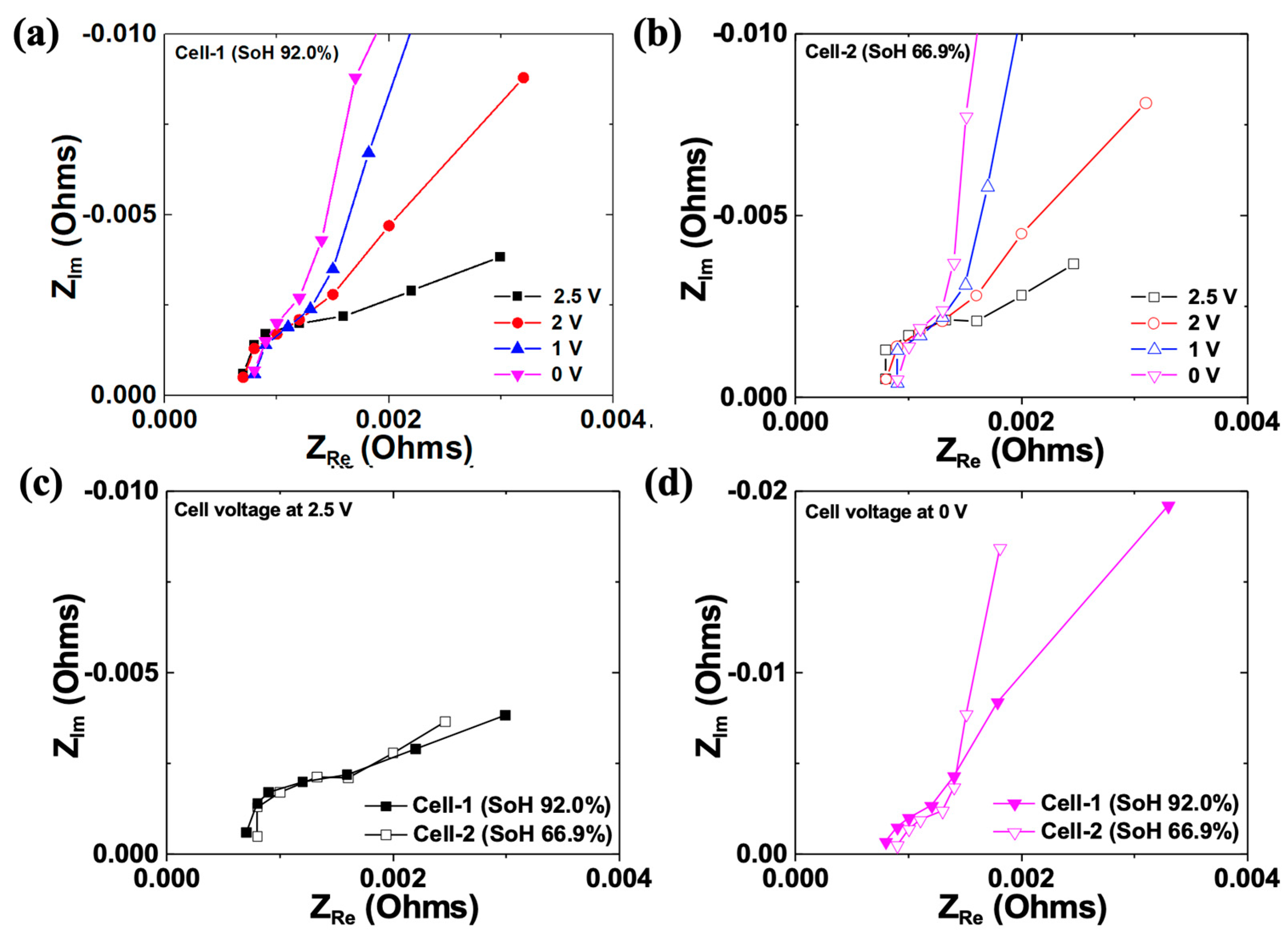
3. Results and Discussion
4. Conclusions
Author Contributions
Funding
Data Availability Statement
Conflicts of Interest
References
- Gaines, L.; Dai, Q.; Vaughey, J.T.; Gillard, S. Direct Recycling R&D at the ReCell Center. Recycling 2021, 6, 31. [Google Scholar]
- Hua, Y.; Liu, X.; Zhou, S.; Huang, Y.; Ling, H.; Yang, S. Toward Sustainable Reuse of Retired Lithium-ion Batteries from Electric Vehicles. Resour. Conserv. Recycl. 2020, 168, 105249. [Google Scholar] [CrossRef]
- Chen, H.; Shen, J. A degradation-based sorting method for lithium-ion battery reuse. PLoS ONE 2017, 12, e0185922. [Google Scholar] [CrossRef] [Green Version]
- Arshad, F.; Li, L.; Amin, K.; Fan, E.; Manurkar, N.; Ahmad, A.; Yang, J.; Wu, F.; Chen, R. A Comprehensive Review of the Advancement in Recycling the Anode and Electrolyte from Spent Lithium Ion Batteries. ACS Sustain. Chem. Eng. 2020, 8, 13527–13554. [Google Scholar] [CrossRef]
- Chitre, A.; Freake, D.; Lander, L.; Edge, J.; Titirici, M.-M. Towards a More Sustainable Lithium-Ion Battery Future: Recycling LIBs from Electric Vehicles. Batter. Supercaps 2020, 3, 1126–1136. [Google Scholar] [CrossRef]
- Fan, E.; Li, L.; Wang, Z.; Lin, J.; Huang, Y.; Yao, Y.; Chen, R.; Wu, F. Sustainable Recycling Technology for Li-Ion Batteries and Beyond: Challenges and Future Prospects. Chem. Rev. 2020, 120, 7020–7063. [Google Scholar] [CrossRef]
- Ren, G.-X.; Xiao, S.-W.; Xie, M.-Q.; Pan, B.; Chen, J.; Wang, F.-G.; Xia, X. Recovery of valuable metals from spent lithium ion batteries by smelting reduction process based on FeO–SiO2–Al2O3 slag system. Trans. Nonferrous Met. Soc. China 2017, 27, 450–456. [Google Scholar] [CrossRef]
- Xiao, S.; Ren, G.; Xie, M.; Pan, B.; Fan, Y.; Wang, F.; Xia, X. Recovery of Valuable Metals from Spent Lithium-Ion Batteries by Smelting Reduction Process Based on MnO–SiO2–Al2O3 Slag System. J. Sustain. Met. 2017, 3, 703–710. [Google Scholar] [CrossRef]
- Yadav, P.; Jie, C.J.; Tan, S.; Srinivasan, M. Recycling of cathode from spent lithium iron phosphate batteries. J. Hazard. Mater. 2020, 399, 123068. [Google Scholar] [CrossRef]
- Yao, Y.; Zhu, M.; Zhao, Z.; Tong, B.; Fan, Y.; Hua, Z. Hydrometallurgical Processes for Recycling Spent Lithium-Ion Batteries: A Critical Review. ACS Sustain. Chem. Eng. 2018, 6, 13611–13627. [Google Scholar] [CrossRef]
- Fu, Y.; He, Y.; Li, J.; Qu, L.; Yang, Y.; Guo, X.; Xie, W. Improved hydrometallurgical extraction of valuable metals from spent lithium-ion batteries via a closed-loop process. J. Alloys Compd. 2020, 847, 156489. [Google Scholar] [CrossRef]
- Esfahani, M.H.; Zinatloo-Ajabshir, S.; Naji, H.; Marjerrison, C.A.; Greedan, J.E.; Behzad, M. Structural characterization, phase analysis and electrochemical hydrogen storage studies on new pyrochlore SmRETi2O7 (RE = Dy, Ho, and Yb) microstructures. Ceram. Int. 2023, 49, 253–263. [Google Scholar] [CrossRef]
- Zinatloo-Ajabshir, S.; Morassaei, M.S.; Salavati-Niasari, M. Eco-friendly synthesis of Nd2Sn2O7–based nanostructure materials using grape juice as green fuel as photocatalyst for the degradation of erythrosine. Compos. Part B Eng. 2019, 167, 643–653. [Google Scholar] [CrossRef]
- Rezayeenik, M.; Mousavi-Kamazani, M.; Zinatloo-Ajabshir, S. CeVO4/rGO nanocomposite: Facile hydrothermal synthesis, characterization, and electrochemical hydrogen storage. Appl. Phys. A 2022, 129, 47. [Google Scholar] [CrossRef]
- Zinatloo-Ajabshir, S.; Salehi, Z.; Salavati-Niasari, M. Synthesis of dysprosium cerate nanostructures using Phoenix dactylifera extract as novel green fuel and investigation of their electrochemical hydrogen storage and Coulombic efficiency. J. Clean. Prod. 2019, 215, 480–487. [Google Scholar] [CrossRef]
- Wang, Y.; Leung, D.Y.C. A high-performance aluminum-feed microfluidic fuel cell stack. J. Power Sources 2016, 336, 427–436. [Google Scholar] [CrossRef]
- Sethurajan, M.; Gaydardzhiev, S. Bioprocessing of spent lithium ion batteries for critical metals recovery—A review. Resour. Conserv. Recycl. 2020, 165, 105225. [Google Scholar] [CrossRef]
- Piątek, J.; Afyon, S.; Budnyak, T.M.; Budnyk, S.; Sipponen, M.H.; Slabon, A. Sustainable Li-Ion Batteries: Chemistry and Recycling. Adv. Energy Mater. 2020, 11, 2003456. [Google Scholar] [CrossRef]
- Xu, P.; Dai, Q.; Gao, H.; Liu, H.; Zhang, M.; Li, M.; Chen, Y.; An, K.; Meng, Y.S.; Liu, P.; et al. Efficient Direct Recycling of Lithium-Ion Battery Cathodes by Targeted Healing. Joule 2020, 4, 2609–2626. [Google Scholar] [CrossRef]
- Sloop, S.; Crandon, L.; Allen, M.; Koetje, K.; Reed, L.; Gaines, L.; Sirisaksoontorn, W.; Lerner, M. A direct recycling case study from a lithium-ion battery recall. Sustain. Mater. Technol. 2020, 25, e00152. [Google Scholar] [CrossRef]
- Ojanen, S.; Lundström, M.; Santasalo-Aarnio, A.; Serna-Guerrero, R. Challenging the concept of electrochemical discharge using salt solutions for lithium-ion batteries recycling. Waste Manag. 2018, 76, 242–249. [Google Scholar] [CrossRef] [PubMed]
- Torabian, M.M.; Jafari, M.; Bazargan, A. Discharge of lithium-ion batteries in salt solutions for safer storage, transport, and resource recovery. Waste Manag. Res. 2021, 40, 402–409. [Google Scholar] [CrossRef] [PubMed]
- Juarez-Robles, D.; Vyas, A.A.; Fear, C.; Jeevarajan, J.A.; Mukherjee, P.P. Overdischarge and Aging Analytics of Li-Ion Cells. J. Electrochem. Soc. 2020, 167, 090558. [Google Scholar] [CrossRef]
- Gaines, L. The future of automotive lithium-ion battery recycling: Charting a sustainable course. Sustain. Mater. Technol. 2014, 1, 2–7. [Google Scholar] [CrossRef] [Green Version]
- Langner, T.; Sieber, T.; Acker, J. Studies on the deposition of copper in lithium-ion batteries during the deep discharge process. Sci. Rep. 2021, 11, 6316. [Google Scholar] [CrossRef] [PubMed]
- Wu, L.; Zhang, F.-S.; He, K.; Zhang, Z.-Y.; Zhang, C.-C. Avoiding thermal runaway during spent lithium-ion battery recycling: A comprehensive assessment and a new approach for battery discharge. J. Clean. Prod. 2022, 380, 135045. [Google Scholar] [CrossRef]
- Arno Kwade, J.D. Recycling of Lithium-Ion Batteries; Springer: Cham, Switzerland, 2018. [Google Scholar]
- Lim, A.E.; Lam, Y.C. Electroosmotic Flow Hysteresis for Fluids with Dissimilar pH and Ionic Species. Micromachines 2021, 12, 1031. [Google Scholar] [CrossRef]
- Lim, A.E.; Lim, C.Y.; Lam, Y.C. Electroosmotic flow hysteresis for dissimilar ionic solutions. Biomicrofluidics 2015, 9, 024113. [Google Scholar] [CrossRef] [Green Version]
- Li, J.; Wang, G.; Xu, Z. Generation and detection of metal ions and volatile organic compounds (VOCs) emissions from the pretreatment processes for recycling spent lithium-ion batteries. Waste Manag. 2016, 52, 221–227. [Google Scholar] [CrossRef]
- Goodship, V.; Stevels, A.; Huisman, J. Waste Electrical and Electronic Equipment (WEEE) Handbook; Woodhead Publishing: Sawston, UK, 2019. [Google Scholar]
- Rouhi, H.; Karola, E.; Serna-Guerrero, R.; Santasalo-Aarnio, A. Voltage behavior in lithium-ion batteries after electrochemical discharge and its implications on the safety of recycling processes. J. Energy Storage 2021, 35, 102323. [Google Scholar] [CrossRef]
- Zhang, T.; He, Y.; Ge, L.; Fu, R.; Zhang, X.; Huang, Y. Characteristics of wet and dry crushing methods in the recycling process of spent lithium-ion batteries. J. Power Sources 2013, 240, 766–771. [Google Scholar] [CrossRef]
- Shaw-Stewart, J.; Alvarez-Reguera, A.; Greszta, A.; Marco, J.; Masood, M.; Sommerville, R.; Kendrick, E. Aqueous solution discharge of cylindrical lithium-ion cells. Sustain. Mater. Technol. 2019, 22, e00110. [Google Scholar] [CrossRef]
- Chikkannanavar, S.B.; Bernardi, D.M.; Liu, L. A review of blended cathode materials for use in Li-ion batteries. J. Power Sources 2014, 248, 91–100. [Google Scholar] [CrossRef]
- Gao, J.; Manthiram, A. Eliminating the irreversible capacity loss of high capacity layered Li[Li0.2Mn0.54Ni0.13Co0.13]O2 cathode by blending with other lithium insertion hosts. J. Power Sources 2009, 191, 644–647. [Google Scholar] [CrossRef]
- Cabana, J.; Kang, S.-H.; Johnson, C.S.; Thackeray, M.M.; Grey, C.P. Structural and electrochemical characterization of composite layered-spinel electrodes containing Ni and Mn for Li-ion batteries. J. Electrochem. Soc. 2009, 156, A730. [Google Scholar] [CrossRef]
- Albertus, P.; Christensen, J.; Newman, J. Experiments on and modeling of positive electrodes with multiple active materials for lithium-ion batteries. J. Electrochem. Soc. 2009, 156, A606. [Google Scholar] [CrossRef]
- Jeong, S.K.; Shin, J.S.; Nahm, K.S.; Prem Kumar, T.; Stephan, A.M. Electrochemical studies on cathode blends of LiMn2O4 and Li[Li1/15Ni1/5Co2/5Mn1/3O2]. Mater. Chem. Phys. 2008, 111, 213–217. [Google Scholar] [CrossRef]
- Sekushin, N.A. Equivalent circuit of Warburg impedance. Russ. J. Electrochem. 2009, 45, 828–832. [Google Scholar] [CrossRef]
- Oldenburger, M.; Bedürftig, B.; Gruhle, A.; Grimsmann, F.; Richter, E.; Findeisen, R.; Hintennach, A. Investigation of the low frequency Warburg impedance of Li-ion cells by frequency domain measurements. J. Energy Storage 2018, 21, 272–280. [Google Scholar] [CrossRef]
- Karden, E.; Buller, S.; De Doncker, R.W. A method for measurement and interpretation of impedance spectra for industrial batteries. J. Power Sources 2000, 85, 72–78. [Google Scholar] [CrossRef]
- Oldenburger, M.; Bedürftig, B.; Gruhle, A.; Richter, E. A new approach to measure the non-linear Butler–Volmer behavior of electrochemical systems in the time domain. J. Energy Storage 2017, 14, 16–21. [Google Scholar] [CrossRef]
- Shen, S.; Sadoughi, M.; Li, M.; Wang, Z.; Hu, C. Deep convolutional neural networks with ensemble learning and transfer learning for capacity estimation of lithium-ion batteries. Appl. Energy 2020, 260, 114296. [Google Scholar] [CrossRef]


| Type | Method | Ref. |
|---|---|---|
| Physical | Thermal pre-treatment | [31] |
| Chemical | Salt water | [21,22,30,32,33,34] |
| Electrical | Electrical Discharge | This article |
| Other | Liquid nitrogen | [21] |
| Sample Name | Thickness (mm) | |
|---|---|---|
| LIB Cell-1 | LIB Cell-2 | |
| As disassembly cell | 10.2 | 10.4 |
| Discharged to 2.5 V | 10.2 | 10.4 |
| Discharged to 2 V | 10.4 | 10.9 |
| Discharged to 1 V | 11.1 | 14.8 |
| Discharged to 0 V | 12.1 | 22.4 |
Disclaimer/Publisher’s Note: The statements, opinions and data contained in all publications are solely those of the individual author(s) and contributor(s) and not of MDPI and/or the editor(s). MDPI and/or the editor(s) disclaim responsibility for any injury to people or property resulting from any ideas, methods, instructions or products referred to in the content. |
© 2023 by the authors. Licensee MDPI, Basel, Switzerland. This article is an open access article distributed under the terms and conditions of the Creative Commons Attribution (CC BY) license (https://creativecommons.org/licenses/by/4.0/).
Share and Cite
Lee, H.; Kim, Y.-T.; Lee, S.-W. Optimization of the Electrochemical Discharge of Spent Li-Ion Batteries from Electric Vehicles for Direct Recycling. Energies 2023, 16, 2759. https://doi.org/10.3390/en16062759
Lee H, Kim Y-T, Lee S-W. Optimization of the Electrochemical Discharge of Spent Li-Ion Batteries from Electric Vehicles for Direct Recycling. Energies. 2023; 16(6):2759. https://doi.org/10.3390/en16062759
Chicago/Turabian StyleLee, Hyunseok, Yu-Tack Kim, and Seung-Woo Lee. 2023. "Optimization of the Electrochemical Discharge of Spent Li-Ion Batteries from Electric Vehicles for Direct Recycling" Energies 16, no. 6: 2759. https://doi.org/10.3390/en16062759