1. Introduction
The correct management of waste and the use of renewable energy sources are crucial issues which are increasingly influencing the focus of the agenda of policy makers of the European Union [
1]. The continuous increase in waste production, the contribution to global warming and the climate changes associated to their confinement in landfills have led to the development of efficient waste to energy technologies (WtE) to improve the energy recovery from the waste [
2]. To face the ever-increasing issue of energy consumption and related environmental impact caused by all the energy sectors, the European Union (EU) issued several step-by-step directives aiming to achieve a full decarbonization by 2050 [
3]. In this path, the Renewable Energy Directive—Directive (EU) 2018/2001, RED II—established a common framework for the promotion of energy from renewable sources in the EU and set a binding target of 32% for the overall share of energy from renewable sources in the EU’s gross final consumption of energy by 2030 [
4]. As a further step, the “fit for 55” package of the Directive issued in 2021 established that an overall reduction by 55% of Greenhouse Gases (GHG) compared to 1990 should be reached by the end of 2030 [
5]. To this scope, several innovations in terms of energy taxation, energy trading systems and carbon border adjustment mechanisms were introduced [
6]. More specifically, the necessity of decarbonizing the road transport sector was highlighted both in the RED II and the “fit for 55”, pointing out that the integration of alternative fuels refueling stations are currently mandatory to meet the energy goals [
7]. In particular, a recent EU Concilium established that by 2035, all the new registered road vehicles should be emissions-free [
8].
To this scope, electric vehicles cannot be considered as the unique solution to fully decarbonize the road transport sector since the amount of electricity required to meet the vehicles’ demand could not be provided only by renewables [
9]. Furthermore, the necessity of adequate infrastructures to renovate the energy transmission and distribution through the current electric grid represents a relevant issue [
10]. Moreover, these issues are even enhanced when considering hydrogen vehicles, since the hydrogen production and distribution infrastructure still only exist at a prototypal level [
11]. Thus the usage of fuel cell vehicles is still premature for the near term future [
12]. In particular, the production of biofuels for the biomethane from anaerobic digestion and a biogas upgrading process, is getting more and more appealing [
13]. The most interesting aspect is that biofuels can be produced by the means of several types of biomasses [
14]. On the one hand, this allows one to exploit a renewable energy source that is programmable, different from the solar and wind sources which are unpredictable [
14]. On the other hand, the role of bioenergy is important for achieving renewable energy targets, in synergy with the concept of a circular economy [
15]. Moreover, the production of biomethane, and biofuels in general, allows the countries to reduce their energy dependence and reduce the energy costs, as recently happened due to the war in Ukraine [
16]. A worldwide urgent action is necessary which aims for the recovery and valorization of waste and biomass, in order to produce valuable materials and energy [
17].
In this framework, the anaerobic digestion (AD) of the organic fraction of the municipal solid waste (OFMSW) plays a pivotal role, and it is a good opportunity in regards to both the need for waste disposal and the production of energy by renewable sources [
18]. The work of Ampese et al. [
19] proves that the AD process represents a hot topic focus of the scientific research, and that the use of renewable fuels becomes, increasingly, a worldwide trend.
Anaerobic digestion is a process by which almost any organic waste can be biologically converted into another species, due to a series of metabolic reactions such as hydrolysis, acidogenesis, acetogenesis and methanogenesis [
20]. The conversion takes place thanks to different microbial species in anoxic conditions [
21]. AD occurs in suitable reactors, and Mahmudul et al. report a review on the pros and cons of them [
22]. Continuous stirred-tank reactors (CSTRs, which use mechanical agitation or effluent) and plug flow reactors (PFR, where the reactor content is propelled along a horizontal reactor) are able to better control the biological conditions due to the variability of the OFMSW characteristics [
23] and are more commonly used for biogas production [
24]. PFRs exhibit several advantages in comparison to CSTRs, such as an appropriate use of the working volume, higher capacity for overloads, more protection against acidification and the generation of concentration profiles along the reactor [
25]. The kinetics of biogas production is high due to a plurality of factors: high concentration of organic matter in the initial sections of the reactor, the near absence of fermentable matter and a low concentration of microorganisms at the end of the process [
26]. On the other hand, PFRs may undergo instabilities due, for example, to the cascading acidification that results from the low local retention time of each section of the reactor [
25].
The final products are the digestate and biogas, which can be used for energy purposes [
27]. The digestate represents the solid residual, rich in readily available macro- and micro-nutrients which can be used in agriculture as biofertilizer [
28]. The biogas is a mixture of gases that mainly includes methane (CH
4) and carbon dioxide (CO
2), with small amounts of hydrogen (H
2), nitrogen (N
2), hydrogen sulphide (H
2S), oxygen (O
2), water (H
2O) and saturated hydrocarbons (i.e., ethane and propane) [
29]. Biogas can be utilized to generate electricity and heat separately, or for combined heat and power (CHP) generation [
30]. If biogas is purified and upgraded to biomethane, it can be fed into the natural gas grid and/or used as fuel for vehicles [
31]. The first process is a cleaning aimed to remove the harmful and toxic compounds [
32], such as H
2S. Conversely, the upgrading process aims at decreasing CO
2 content, simultaneously increasing the heating value of the biogas [
33]. More than 1000 biomethane plants were operating worldwide during 2020 [
34]. In Europe, more and more biomethane plants have been installed in the past few years: numbering from 187 plants in 2011 up to a total of 729 plants in 2020. Germany presents the highest number of biomethane plants, followed by the UK and Sweden. Pressure swing absorption (PSA), water, organic solvent, chemical scrubbing and separation employed through membrane and cryogens are a few of the commercially available biogas purification systems [
35]. They are widely employed, accounting for 98% of all upgrading facilities. A common factor of all these techniques is that the removed CO
2 is normally released back into the atmosphere [
36]. The membrane separation process is particularly appealing for biogas upgrading, due to its moderate energy consumption, good selectivity, easily engineered modules and therefore lower costs. High CH
4 recovery efficiency can be reached (>96%), while pure CO
2 can be obtained. The main disadvantage of the membrane separation process is that multiple steps are required to reach high purity [
37]. Since the commercially applied technologies for biogas upgrading are energy-intensive [
38], researchers’ efforts moved toward the study of new technologies. Starr et al. analyzed alkaline with regeneration (AwR) and bottom ash upgrading (BABIU), which not only selectively remove CO
2 from the biogas but they also store it [
36]. However, data for these novel technologies is actually based on laboratory values and, therefore, they need further investigations. A direct hydrogen injection [
39] and additives [
40] are alternatives in situ biogas upgrading technologies. However, the first one needs a significant improvement to reduce the energy used for H
2 gas-to-liquid transfer in order to be economically feasible, [
41] while the second one affects the post-treatment of digestate [
42].
The biogas production and Its composition do not depend only on OFMSW [
43] characteristics, but also on process conditions (batch or continuous; wet or dry; mesophilic or thermophilic fermentation) [
44]. Temperature is one of the main factors affecting the anaerobic digestion [
45]; it significantly affects the activity of the main microbial species [
46] responsible for the biogas production, and it is necessary that the reactor is equipped with a heating system to control its temperature. The anaerobic digestion process can take place under mesophilic conditions with an operating temperature ranging from 35 °C to 40 °C and from 50 °C to 60 °C under thermophilic conditions [
47]. Because mesophilic digestion operates at a lower temperature, digestion at this temperature regime is slower and yields a lower amount of biogas. However, mesophilic digesters remain attractive because of their lower heating costs compared with thermophilic digesters [
48]. Therefore, biological and thermal models have to be implemented to describe the anaerobic digestion process. The biological model is used to predict the amount of biogas produced by chemical reactions, which are simulated considering their specific operating temperature. A detailed thermal model is also required to simulate the digester thermal behavior and predict the heat transfer between the digester and the water heat exchanger or the environment [
49].
A biogas plant requires thermal energy to supply the digester and to keep its temperature within the designed operating range. It requires electric energy to activate some equipment, as pumps and mechanical stirring add to the biogas upgrading process. Once again, in the framework of the above-mentioned EU goals, the biogas plant can be integrated with renewables to avoid or reduce the use of natural gas and electric power from the grid. In particular, solar technologies (solar thermal collectors, photovoltaic panels or photovoltaic/thermal collectors) can be easily integrated in these plants [
50]. A new conception of a solar anaerobic digestion unit was proposed by Ouhammoun et al. [
51]. The plant consists of an Upflow Anaerobic Sludge Blanket (UASB) digester coupled with a flat plate collector (FPC). Two storage tanks are also included to cover the heat demand of the digester when the solar irradiance is not available. To analyze its performance, a modelling simulation was developed and implemented in a TRNSYS platform, and the results showed that the current system can achieve 100% energy autonomy. Lombardi et al. investigated the possibility to integrate thermal solar collectors into a plant, including a CSTR and an upgrading unit [
52]. The supplied solar thermal energy allows one to save a certain amount of biogas used for heating the reactor, enhancing the production of biomethane. The thermal and economic analyses were performed using different collector types and for different geographical locations. They observed that economic acceptability can be reached only using the less expensive collector, even if its efficiency determines lower biomethane savings. In the work of Gaballah et al. [
53], experiments on a household digester have been conducted aiming to investigate the potential of integrated solar heating techniques to increment its performance in China’s cold regions. Two cases have been analyzed. The first one consists in a digester equipped with a solar greenhouse, while the second case provides the addiction of a solar water heating system and a heat exchanger under the digester. The results have shown that using an integrate solar energy allows an increase in the slurry temperature, but no significant variation in the biomethane production. Mahmudul at al. provided a review of the most recent studies from the relevant academic literature on waste to energy technology (particularly AD technology) for biogas production, and the application of a solar-assisted biodigester (SAB) system [
54]. In this system, solar energy is collected from sunlight using the collector and converted into electricity using a battery and DC-AC converter, which provide the appropriate temperature for converting the waste into energy. The study revealed that the solar-assisted AD system produces less pollution and exhibits a better performance, compared with the conventional AD system. Li et al. showed theoretical and experimental results of a solar temperature-controlled biogas production system [
55]. The plant was developed in Lanzhou City, China, mainly consisting of an insulated anaerobic reactor and a solar collector with 30 sticks of Φ58 × L1800 mm evacuated tubes. Their work represents a scientific basis and engineering reference for the application of biogas production that is temperature-controlled by solar energy, and has important value for the efficient and low-cost anaerobic digestion treatment of agricultural and animal husbandry wastes in cold and arid areas. Conversely, Khalid et al. [
56] and successively Zaied et al. [
57] used a photovoltaic system to warm up the palm oil mill effluent and cattle manure mixture, in order to maintain the required reactor temperature. The proposed biogas plant seems to be economically feasible; a payback period of approximately 5 years may be achieved if this technology is used on a large scale. The biogas plant electric demand is due to its own equipment operation, such as pumps and mixers, and is mainly due to the upgrading technologies. A rooftop photovoltaic system is used to supply the electric energy demand of an integrated AD-composting plant operating in South Italy, and described in the work of La Pera et al. [
58]. It covers an area of approximately 12,000 m
2 with electricity production, for plant activities relative to the year 2020 of approximately 3 MW. Aiming at achieving a more sustainable and efficient biomethane production, Tian et al. proposed a novel system, which integrates concentrating a photovoltaic/thermal hybrid (C-PV/T) in the upgrading biogas [
59]. Due to the ability to produce electricity and heat simultaneously and efficiently, C-PV/T can provide the demand of both the electricity and heat required by the regeneration of the solvent in the chemical absorption upgrading process. Without the storage of energy, C-PV/T could only provide 17% of the heat demand and 51.1% of the electricity demand during the process. At the same time, Hao et al. presented a hybrid digestion system, integrated with a concentrated photovoltaic/thermal (C-PV/T) system for biogas production [
60]. In this case, the results show that approximately 7% of the heat consumption and 12% of the electricity consumption of the biogas plant can be covered by solar energy, by using the produced heat in a cascading way according to the operating temperature of different processes. Biogas yield is expected to be increased by 1.7% with such systems, and the payback period is approximately 10 years. Experimental studies on the contribution of solar energy for the heating of an anaerobic digestor have been conducted by Darwesh et al. [
61]. In particular, the required mesophilic conditions have been satisfied, integrating an evacuated tube solar collector with an auxiliary electrical heater placed inside the storage tank. The latter was necessary to provide for the unavailability of solar energy during the night and at different times. The solar energy system was able to cover approximately 75% of the energy demand of the reactor, considering an operational temperature of 37 °C. The cost analysis showed that the project has good economic feasibility with a payback period of 1.7 years. Mehrpooya et al. presented a study on an integrated process of cryogenic biogas upgrading, by using renewable energy resources for sustainable development [
62]. A parabolic trough solar collector (PTC), organic Rankine cycle (ORC) power system and absorption refrigeration cycle are used in this process to separate the impurity of raw biogas. The PTC supplies the required heat for the ORC and absorption refrigeration cycles. The results show that an integration upgrading process allows one to obtain an acceptable biogas purification and an overall exergy efficiency of 71.6%. In another study, Mehrpooya et al. designed a solar-driven water scrubbing process, integrated with flat plate solar collectors and a Kalina power cycle [
63]. The power required for the compressor and pumps was provided by the Kalina cycle, recovering solar thermal energy and the heat of biogas compression. An auxiliary heater was employed to provide heat in case of scarce/null solar radiation. The water scrubbing process is capable of removing the CO
2 and H
2S contents, and the exergy efficiency of the proposed integrated system is found to be 92.36%. A life cycle energy and cost analysis of biogas plants integrated with solar PV systems has been conducted by Ali et al. [
64]. They have collected data from 20 small scale plants and 20 PV systems from 3 different sub-districts of Bangladesh. The study suggests that the higher the plant size, the higher the efficiency in terms of produced biogas, but also the higher the installation costs. In work by Cappiello et al. [
65], a comparison between two biogas upgrading technologies coupled with photovoltaic panels and an electric energy storage system was proposed. A photovoltaic field of 200 kW and a lithium-ion battery of 182 kWh allow one to achieve an almost grid-independent plant, producing enough electricity to be able to meet approximately 92% of the plant demand. Su et al., developed a mathematical model to simulate a hybrid system, including concentrated photovoltaic thermal (C-PV/T) collectors and biogas upgrading technology [
66]. The thermal energy of the solar collectors is used for heating the digester unit, whereas the electric energy is used to supply the biogas upgrading unit to produce biomethane. The proposed configuration allows the reduction in the amount of electricity withdrawn from the grid by 48.38%, increasing biomethane production by 86.08%.
On the basis of the previous literature review, the anaerobic digestion process and the mathematical models aiming to describe the biochemical and biological aspects occurring during the waste stabilization are well known and consolidated. However, the works that describe the thermal aspects of the process and their influence on the biological aspects are yet few. Moreover, knowing the fundamental role of the anaerobic digestion process in the aim of a more aware waste management and biogas production, the attention of the current scientific research is focused on making the process more and more self-sufficient and independent by the use of natural gas and electric power from the grid. Hence the need to have a simulation model to analyze a so-made integrated system. It is within this context that this work arises.
The authors have simulated the anaerobic digestion process through a new model that takes into account both the kinetics of reactions and the heat exchanges occurring inside the reactor. The last has been integrated with renewables to meet its energy demand. At the end, the whole plant has been implemented in a dynamic simulation tool to test the influence of the environmental condition variations on the system’s performance. In particular, this work proposes a novel system layout for the biomethane production by the anaerobic digestion of OFMSW in a plug flow reactor, working under mesophilic conditions, combined with solar thermal collectors. An upgrading unit based on the membrane technology completes the biogas plant. It is coupled with an evacuated tube collector field and a photovoltaic field to match its energy demand.
In order to evaluate the energy efficiency and the economic feasibility of the investigated plant, the following advances with respect to the state of the art are included:
A digester model able to describe the biological aspects of the digestion process and the thermal heat exchange was implemented;
A dynamic simulation model was implemented in a TRNSYS environment to evaluate the time-dependent biogas flow rate, taking into account the variation of the ambient temperature. The upgrading unit was simulated by an in-house developed model, since this component is not available in TRNSYS;
A thermoeconomic model was developed considering in detail the capital and operating costs of the overall plant and including, also, the public incentive acknowledged due to the biomethane produced and injected into the public gas grid.
2. System and Method
This work presents a dynamic analysis of a fully renewable plant for the production of biomethane from Organic Fraction of Municipal Solid Waste (OFMSW). The core of the plant is a Plug Flow Reactor (PFR), where the anaerobic digestion process occurs. It is designed to work with an input water temperature equal to 55 °C. In order to satisfy the thermal energy demand to control the operating temperature of the digester, the PRF is coupled to a field of evacuated tube solar thermal collectors. Moreover, a photovoltaic field supplies the electric power for the pumps and the upgrading process.
The dynamic simulations of the proposed system were performed in a TRNSYS environment (version 17), including a large library of mathematical models for different components (“Types”). A model to simulate the processes occurring within the PFR was integrated into it. This model was developed with MATLAB, and allows the prediction of the temperature gradient along the reactor and the biogas production from the organic waste. Finally, a thermoeconomic model for a global assessment of the proposed system is also presented.
2.1. Layout
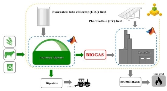
The following
Figure 1 shows the detailed layout of the proposed renewable energy system:
Two main circuits are included in the plant: the thermal and the electricity circuits.
The thermal circuit is split into two parts by the thermal energy storage tank, decoupling the solar loop by the digester water loop. The solar loop is equipped with the pump P1 and a solar field of evacuated tube collectors (ETC). A heat exchanger (HE 1) is also used to prevent the tank from overheating. When the water temperature rises over 80 °C, a counterflow water at a lower temperature is supplied to HE 1 to dissipate the excess heat. If the tank bottom temperature is or the total radiation is , the controller supplies a signal that switches the P1 off in order to prevent thermal energy dissipation, and the water is not sent to the collectors.
On the other side, the hot water is pumped by the constant speed pump P2 toward the auxiliary heater (AH). The set point temperature of the AH is fixed at 55 °C. If the fluid temperature is below the set point, the AH is turned on to heat the water of the cycle before entering the digester. The second heat exchanger (HE 2) at the outlet of the AH is designed to avoid the digester overheating. It rejects the heat to the environment when the water temperature exceeds the reactor operating temperature. The water exiting from the PFR is supplied to the tank, and the thermal circuit is closed.
The electricity circuit includes a photovoltaic (PV) field. An inverter is used to convert the direct current into an alternate current and to manage the maximum power point operation of the PV field. In addition, a lithium-ion battery storage (Lib) is used to limit the electricity exchanged with the grid.
2.2. Anaerobic Digester Model
The anaerobic digester model was described in detail in reference [
49]. It consists of two models: the biological model and the thermal model. The biological model is based on the simplified version of the anaerobic digestion model n.1, the most commonly used mathematical model to describe the AD process [
54]. The thermal model consists of two energy balance equations. The peculiarity of the developed simulation model is the integration of these two models, to simultaneously consider the thermal heat exchange between the waste and the internal heat exchanger and the thermal dissipations toward the environment, along with the temperature-dependent kinetics of the biological model.
The equations constituting the thermal model are the energy balance equation of the digester (Equation (1)) and the heat exchanger equation (Equation (2)).
The two variables are the output water temperature
and the output digestate temperature
. The model takes into account the heat transfer between the OFMSW and the internal heat exchanger in Equation (2) and the heat transfer between the reactor and the environment by the dissipative term
in Equation (1).
The three terms of Equation (3) are the flow rate loss through the digester cover, lateral walls and basement, respectively. Ui are the global heat transfer coefficients, and the overlined terms represent the spatially averaged value.
The reactor and biogas temperatures are assumed to be equal to . It is the most important parameter because it affects the AD process. dramatically affects the kinetics of the microbiological species responsible for the biogas production. Therefore, the thermal model is strictly linked to the biological model, and the is an input parameter for the latter.
The biological model consists of 13 differential mass balance equations, one for each organic matter component. Assuming that the volume occupied by the waste
remains constant, the generic equation can be written as follows:
represents the concentration of the considered substate and is expressed in ; is the kinetic of reaction of the process and is the biological coefficient.
2.3. TRNSYS Model
The majority of the components used in this work were taken from the TRNSYS Library, whereas some other models were specifically developed for the scope of the work and based on manufacturers’ data.
As mentioned in the previous section, it was necessary to develop a model for the simulation of the anaerobic digester, since this component was not available in the TRNSYS Library. The model was developed in Matlab, and it requires as input data the temperature and mass flow rate of water and OFMSW as reported in the following
Table 1.
In particular, the inlet OFMSW temperature was assumed to be equal to the ambient temperature that is from weather data supplied by the “Type 109-TMY2” of the TRNSYS Library. As a result, in addition to the outlet cold water and digestate temperature, the biogas flow rate and the thermal flow rate exchanged between water and waste are obtained.
The produced biogas is supplied to an upgrading process. This component is not available in the TRNSYS Library, and a suitable model was purposely developed. The model predicts the biomethane yield after the upgrading process. The upgrading unit consists of a 3-stages selective membrane system, equipped with 3 compressors [
67]. In this membrane separation process, CO
2 is removed from the biogas mixture by means of a physical filtration through hollow fiber selective membranes [
37]. The obtained biomethane was predicted on the basis of some specific simplifying assumptions:
Given the biogas volumetric flow rate
, the biomethane volumetric flow rate was calculated as follows:
and the electric power requested by the upgrading process was equal to:
2.4. Thermoeconomic Model
To evaluate the energy efficiency and the economic feasibility of the investigated plant, the energy and economic model are presented. The proposed system is a new plant to realize completely from scratch. The produced biomethane is injected into the natural gas grid.
The Simple Pay Back (SPB) period was calculated to estimate the system profitability. It is equal to the ratio between the total investment
and the yearly costs
for the proposed system:
The capital costs of all the components of the plant are also calculated. The most expensive component is the digester, being its capital cost related to its volume
:
The capital cost of the evacuated solar collectors is assessed as a function of their active surface area
:
The photovoltaic capital cost includes the cost for the panels and the cost for the battery:
where
is the peak power depending on the PV area
and
is the battery capacity.
The cost of the tank, including all the safety equipment and thermal insulation, is referred to its volume
[
68]:
The cost of the pumps is expressed as a function of their nominal mass flow rate
[
68]:
According to the values available in Chen et al.’s work [
37], the upgrading unit capital cost is calculated as follows:
The operative costs are due to the energy and maintenance costs
assessed as approximately
of the total investment costs:
where
is the electric energy withdrawn from the grid,
is the thermal energy provided by the woodchip (
) AH and
is the volume of the biomethane exported to the grid.
The primary energy (
) required by the proposed system is evaluated as follows:
It is equal to the PE consumption due to the electric energy withdrawn from the grid. The PE consumption due to AH is null because a woodchip fire was considered.
For the evaluation of the CO
2, it is worth noting that all the energy/fuels produced by renewables (biomass and solar) do not produce any CO
2. In fact, no CO
2 is emitted by solar collectors. In regards to biomass, it has been assumed that the amount of CO
2 emitted during the energy utilization process is equal to the CO
2 used for the growth of the biomass. Therefore, for the considered plant, CO
2 is only produced for the electricity withdrawn from the grid and produced by conventional fossil fuels-based power plants and can be calculated through the following equation:
The main parameters adopted in such equations are reported in
Table 2.


 ,
, 


