Review

Hydrogen Hydrate Promoters for Gas Storage—A Review

1
Ugelstad Laboratory, Department of Chemical Engineering, Norwegian University of Science and Technology (NTNU), N-7491 Trondheim, Norway
2
Department of Petroleum Engineering, King Fahd University of Petroleum & Minerals, Dhahran 31261, Saudi Arabia
*
Author to whom correspondence should be addressed.
Energies 2023, 16(6), 2667; https://doi.org/10.3390/en16062667
Submission received: 4 January 2023 / Revised: 15 February 2023 / Accepted: 7 March 2023 / Published: 13 March 2023
(This article belongs to the Section I1: Fuel)

Abstract

:
Clathrate and semi-clathrate hydrates have recently been gaining major interest as hydrogen storage material. The benefits of hydrates, such as reversible formation and dissociation, their environmentally friendly nature, economical costs, and lower fire risk, make them one of the most promising hydrogen storage materials. One of the major challenges when storing hydrogen in hydrate crystals is the extreme pressure and temperature conditions required for the formation of hydrogen hydrates. Solving the problems of extreme pressure and temperature through the use of promoter molecules would make these materials a promising storage medium with high potential. Through the use of efficient, economical, and green promoter molecules, hydrogen hydrate can be used to store large amounts of hydrogen economically and safely. This review aims to present a comprehensive summary of the different hydrate promoters that have been tested specifically in terms of hydrogen storage. The hydrate promoters are classed according to the structure of the hydrate crystals they form, i.e., sI, sII, sH, and semi-clathrate hydrate. This review article provides summarized information for readers about the different promoters tested and their benefits and shortcomings.

1. Introduction

Hydrogen fuel production and storage represent one of the most prominent research topics at present. Depending on the method of production, hydrogen fuel can be broadly classified as green, blue, or brown hydrogen [1]. However, all these types of hydrogen fuel face a single major common problem, which is their easy, safe, and cost-effective storage. The future of renewable energy sources depends on the efficient storage of hydrogen fuel [2]. Geothermal energy, solar energy, ocean wave energy, hydropower, and nuclear energy have been employed successfully in a variety of applications [3,4]. However, the major drawback associated with these energy sources is that they cannot be directly utilized as fuel in most applications. The storage of these types of energy is also a major challenge. These energy sources can be used to produce fuel, such as hydrogen. Hydrogen is at the forefront in the current transitioning phase and represents the next sustainable fuel [5]. Green hydrogen gas is recognized as the most favorable substitute for fossil fuels. Hydrogen gas is considered green fuel if its production does not involve the emission of carbon dioxide, i.e., if the energy utilized to produce hydrogen is produced using renewable sources [6]. Hydrogen has very high fuel efficiency in comparison to conventional fuels, with a calorific value of 141.7 MJ/Kg [7,8,9]. Another advantage of using hydrogen is that it can easily replace natural gas for building heating purposes. The existing infrastructure would not require any major changes for the use of hydrogen. Hydrogen fuel could meet 10% of the global demand for building heating by the year 2050 [10]. It has also been predicted that, by 2050, hydrogen fuel will meet 25% of the energy demand in the transportation industry [11]. Depending on the application and use of hydrogen energy, it may pass through various supply chain links. Therefore, one of the most crucial aspects in the development of hydrogen energy as a sustainable energy source is its storage.
Storage of hydrogen fuel entails challenges because of its very low density (0.08 g/L) and extremely flammable nature, even at concentrations as low as 4% in air [5].
However, because of its low density, hydrogen also dissipates very quickly and disperses more rapidly during gas leakages. Under ambient conditions, 1 kg of hydrogen gas occupies approximately 11 m3 [12]. This means that energy input is required to increase the storage density of hydrogen. Hydrogen storage also depends on factors such as the type of application and the purity of the fuel required. In some applications, hydrogen release requires a quick response time, whereas in others, the hydrogen release response time is not so important, and the hydrogen may be required to be released only a few times in a year. The fuel purity also determines the storage mode; for example, in proton-exchange membrane (PEM) fuel cells, very high purity hydrogen is required, whereas, if the hydrogen is combusted with air, the purity is a less critical factor [13,14,15].
Research on the storage of hydrogen can be divided into two categories: hydrogen storage in onboard fuel cell vehicles and large-scale stationary hydrogen storage [13,16,17]. Some of the most common hydrogen storage technologies include high-pressure gas tanks, metal hydrides, cryo-compressed hydrogen storage, porous materials, and hydrogen hydrates [18,19,20,21,22,23]. These hydrogen storage technologies use different physical phenomena and mechanisms to store hydrogen and offer different storage capacities. The mechanisms used for storage range from simple compression, absorption, and liquefaction to physical trapping of the hydrogen. Hydrogen storage materials can be broadly classified in terms of the interaction between the hydrogen and the storage materials, i.e., physisorption and chemisorption [24,25]. In the physisorption mechanism, the molecular hydrogen interacts with the host storage material with the help of weak van der Waals forces [25]. Electrostatic and orbital interactions also contribute. The drawback associated with these interactions is that they are weak and only favored at lower temperatures (77 K). As the temperature increases, the adsorption decreases. The pore size of the storage host material is also a governing parameter on which the gas adsorption depends. It has been found that, with decreasing pore size, the enthalpy of adsorption increases; i.e., the amount of gas adsorption increases with the decrease in pore size [26,27]. In chemisorption, the molecular hydrogen is dissociated into the atomic form after the crossing of the activation energy barrier. Atomic hydrogen can be formed into a disordered solid solution or a compound by allowing it to diffuse into the bulk material [24].
The efficacy of the storage material is a particularly critical aspect that must be considered in the development of hydrogen storage technology in addition to the storage capacity. The efficacy of hydrogen storage technology is a measure of the net energy stored, i.e., how much energy is spent in storing hydrogen and recovering it from the storage medium [28]. The hydrogen storage technology requires the storage of hydrogen in its thermodynamically stable, gaseous state in a comparatively smaller volume with high net stored energy.
Conventional hydrogen storage systems have major limitations. High-pressure tanks are the simplest and most common method for hydrogen storage. They can store large amounts of hydrogen in a comparatively small space, and the material of the cylinder must be able to withstand hydrogen embrittlement due to the extremely high pressures of approximately 35–70 MPa. Moreover, the cylinder should be light and able to resist fire, high temperatures, and abrasion [29,30,31]. Similarly, storing hydrogen in cryogenic tanks requires small volumes for storage. The hydrogen’s volumetric energy density can be increased by liquefying the hydrogen gas through the reduction of its temperature to 20 K. This enables the use of smaller and lighter storage tanks to store the hydrogen. The drawback associated with cryogenic tanks is that approximately 35% of the energy content of the fuel is used for the liquefaction of the gas. This energy requirement is three times greater than the energy required to compress the gas to 70 MPa [32,33]. The metal hydrides, out of all the conventional storage materials, are the most compact ones to store the hydrogen [34]. They are capable of absorbing and discharging the hydrogen. They are broadly classified as binary and intermetallic hydrides [34]. The metal hydrides, despite their advantage of compact size, are not a desirable method of hydrogen storage because of their high metal alloy cost and their demand for large binding energy at elevated pressures for chemisorption of hydrogen [35]. The adsorption of hydrogen into metallic surface is an exothermic reaction, and to release the same hydrogen, heat input is required at lower pressures [36]. These conditions are not desirable in hydrogen storage mediums. Few metal hydrides can adsorb and desorb hydrogen close to ambient conditions, whereas they are not capable of higher gravimetric hydrogen storage. Moreover, the proposed metal hydrides were not able to attain faster dehydrogenation kinetics, which is one of the major requirements for the hydrogen stage medium [37,38]. The materials which store hydrogen with the help of physisorption mechanism such as zeolites, metal organic frameworks, and porous carbon structures store it on porous surfaces. The parameters, such as pore volume, surface area, pore size, etc., determine the storage capacity of the porous storage medium. Studies suggested that the decrease in temperature and increase in pressure promote the physisorption of hydrogen in porous materials. Many studies suggest that porous materials (physisorption based) have a hydrogen storage capacity within acceptable ranges, whereas within the ambient conditions and pressure limits of 1–50 bar, their storage capacity falls below 1%. However, maintaining lower temperatures using liquid nitrogen is found to be uneconomical, and it may lead to operational difficulties as well [39,40,41,42].
Another important and attractive class of hydrogen storage medium is clathrate hydrate [43]. The use of hydrates for the storage of hydrogen is growing in importance worldwide. The use of hydrates for the storage of hydrogen is growing in momentum because of the advantages associated with hydrate technology. In the gaseous form of hydrates, the dissociation kinetics can require swift and small amounts of energy for the dissociation of hydrate crystals, which means that slight variations in the pressure and temperature conditions outside the hydrate crystal stability zone will release stored hydrogen from the system [44]. Moreover, hydrate technology is a green technology; i.e., the hydrate crystals are mainly water molecules [45]. Therefore, hydrate storage can be considered a cheap and safe storage medium with minimal negative environmental impact. The hydrate crystals can also store up to 5 mass% molecular hydrogen [46]. However, the hydrogen hydrate storage medium is also not without its own challenges. A major challenge is the pressure required for the formation of hydrogen hydrate crystal; for example, a pressure of 200 MPa pressure is required for the formation of hydrogen hydrates at 273 K temperature [47,48,49,50,51]. The inclusion of hydrate promoters will help to decrease the pressure requirements during hydrogen hydrate formation. However, none of the studied promoters were able to make the hydrogen hydrate storage meet the technical targets given by the DOE (technical targets for hydrogen storage systems for material handling equipment, Table S1 [52]). The use of hydrogen hydrate promoters influences the structure, storage capacity, and formation kinetics of hydrate crystals. The hydrate crystal promoters are broadly classified as thermodynamic promoters (THP) and kinetic promoters (KHP) [53]. The thermodynamic promoters help to form the hydrate crystals at moderate pressure and temperature conditions; however, the volume of hydrogen stored in crystal structure is reduced due to the occupation of hydrate cage space by THP. On the other hand, KHPs influence the interface of liquid/gas without causing any effect on the operation conditions. THPs in a liquid phase, such as THF, cyclopentane, etc., and in a gaseous phase, such as CO2, CH4, C3H8, etc., were used commonly. Many researchers claim the presence of a “tuning effect” during the use of liquid THPs; however, the tuning effect is still disputed by many. According to this effect, hydrogen storage can be controlled by varying the concentration of the liquid THPs. The most commonly used KHP is sodium dodecyl sulfate (SDS). This review article only focuses on and discusses the hydrogen hydrate promoters specifically studied for hydrogen storage and draws a clear status of hydrate storage technology.
Clathrate hydrates or gas hydrates were first discovered in the year 1810 [44]. These are a class of compounds in which the host molecules form cage-like structures and entrap the guest molecules within these cages. Clathrates can be broadly classified as clathrate hydrates and semi-clathrate hydrates. In clathrate hydrates, the guest molecules and host molecule interact with one another only with the help of weak van der Waals force of attraction, whereas in the semi-clathrate hydrates, the guest molecules participate in the host cage framework via partial hydrogen bonding. Clathrate hydrates were proposed for hydrogen storage in the year 2002 by Mao et al. [46]. It was shown that hydrogen hydrates with a storage capacity of 5.3 wt% can be formed at 249 K and 250 MPa. A further detailed investigation was also performed which measured the hydrogen occupancy in hydrate cages, interaction of hydrogen with water molecules, etc. Pure hydrogen hydrates have the sII structure, which comprises a small dodecahedron cage (512) and large hexakaidecahedron cage (51264). sI and sH hydrate structures are the other two hydrate structure which are found in gas hydrates. Different research studies established that the number of hydrogen molecules entrapped in a hydrate depends on the type of hydrate cage. Two hydrogen molecules can be entrapped in a 512 cage, and four hydrogen molecules can be accommodated in 51264 hydrate cages. Similarly, 435663, 51262, and 51268 hydrate crystal cages can accommodate one, two, and five hydrogen molecules, respectively. Depending upon the total number of hydrogen molecules entrapped in different types of cages, the hydrogen storage capacity for different hydrate structures was estimated. The sI, sII, and sH hydrates can hold up to 6.33 wt%, 4 wt%, and 4.67 wt% hydrogen, respectively. The main role performed by the hydrate promoters is the stabilization of hydrate crystal structures to increase the hydrogen storage capacity. All the hydrate promoters which are studied as hydrogen hydrate promoters are classified into three major groups in the next section. They are grouped according to the hydrate crystal structure they form, i.e., Type sII hydrate crystal promoters, Type sI hydrate crystal promoters, and semi clathrate hydrate crystal promoters.

2. Hydrogen Hydrate Promoters

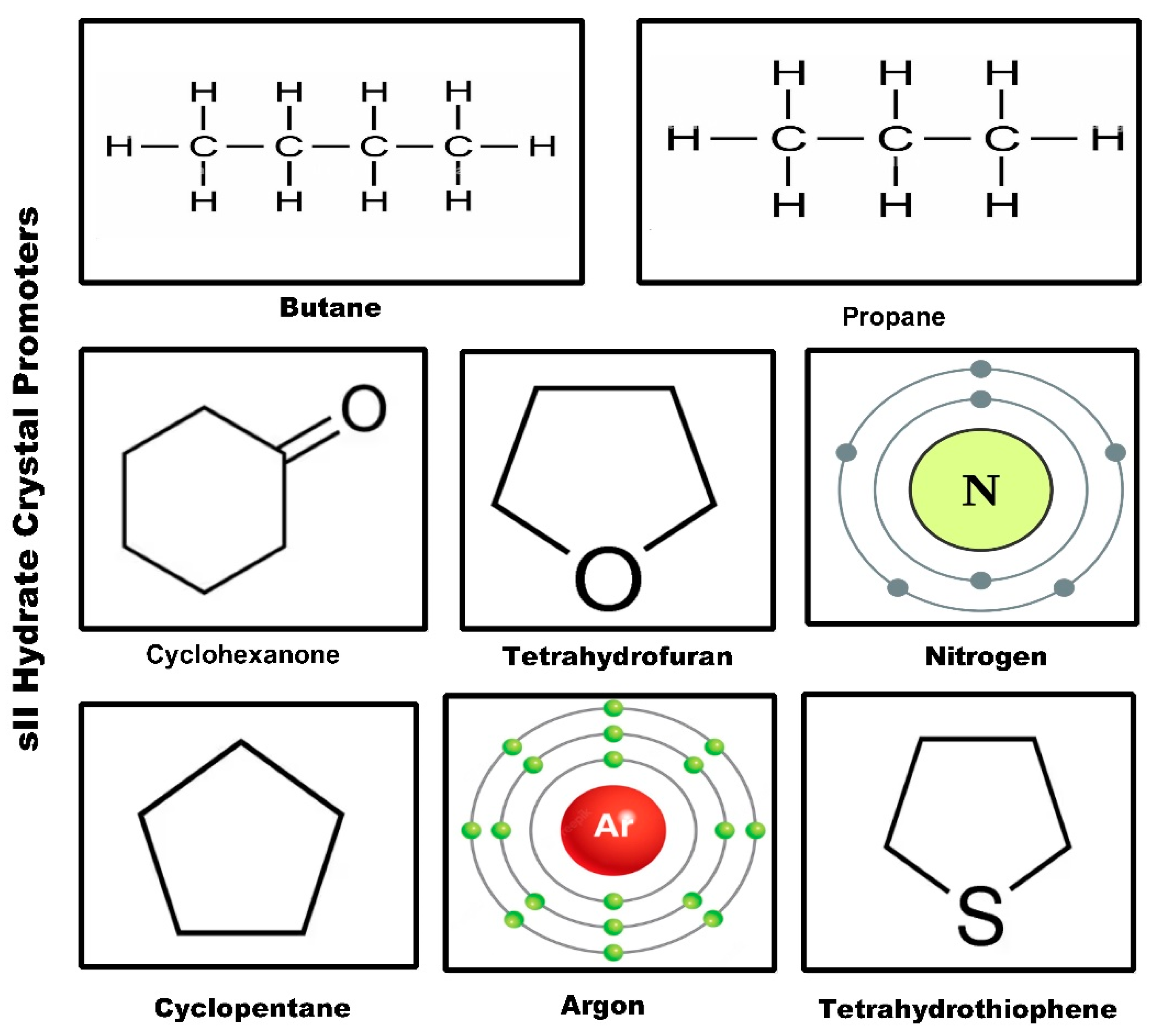
2.1. Type sII Hydrate Crystals

Type sII hydrogen hydrate crystal promoters (Figure 1) include tetrahydrofuran, cyclopentane, cyclohexane, propane, butane, furan, tetrahydrothiophene, argon, and nitrogen.

2.1.1. Tetrahydrofuran (THF)

THF is an organic compound which has physical and chemical attributes such as lower viscosity, being colorless, and water solubility. It is a heterocyclic compound (cyclic ether) with a chemical formula of (CH2)4O. The structure of THF is shown in Figure 1; it consists of four carbon atoms, eight hydrogen atoms, and one oxygen atom. The oxygen in the ring structure is more electronegative in comparison to carbon and nitrogen and thus pulls electron density towards itself by forming the covalent bonds. Because of its polarity, THF readily mixes with polar liquids. THF forms sII hydrate crystals.
Initially, it was presumed that hydrogen was not able to form hydrate crystals because of its inability to provide the desired crystal stabilization due to its smaller molecular size. In 1985, for the first time a theoretical study predicted the formation of hydrogen hydrates at very high pressure and lower temperature conditions in planetary bodies [54]. However, the first hydrogen clathrate was reported by Vos et al. in the year 1993 at a pressure of 0.75–3.1 GPa and 295 K [55]. Hydrogen gas formed sII hydrate crystals in this research study. Florusse et al. (2004) first proposed the use of THF to decrease the pressure required for hydrogen hydrate formation by two orders of magnitude [56]. Hydrogen hydrate formation pressure was decreased to 5 MPa at 279.6 K. However, due to the occupancy of THF in the larger crystal cages, hydrogen storage capacity was decreased to 1 wt% as they only occupy the small cages. This research demonstrated that hydrogen hydrate formation temperature and pressure conditions can be shifted towards ambient conditions with the help of hydrate promoters. Later, Lee et al. (2005) demonstrated that with the help of a ‘tuning effect’, it is possible to increase the amount of hydrogen occupancy in hydrate crystals [57]. In this research, the concentration of THF was decreased from 5.56 mol% to 0.1 mol% at 12 Mpa pressure condition. The highest hydrogen storage of 4.03 wt% was observed at a THF concentration of 0.15 mol%. THF partially occupies the large sII hydrate crystal cages and remaining large cages occupied by the hydrogen. The results were postulated depending upon the high-pressure NMR data and high-pressure Raman spectra of the hydrate crystals at different THF concentrations. However, the 4.03 wt% hydrogen storage capacity study was contradicted by Strobel et al. (2006), where they measured hydrogen storage capacity in volumetric gas uptake and found that irrespective of the THF concentration (varied from 5.56 mol% to 0.5 mol%), a maximum hydrogen uptake of only 1 wt% was achieved [58,59]. Research studies are divided upon the tuning effect in mixed hydrogen hydrates, where some studies supported the tuning effect while others refuted any such effect. Ogata et al., 2008 used Raman spectroscopy to assess two different methods of gas hydrate formation: (a) THF hydrates isothermal pressure swing adsorption at 277.15 K and (b) mixed hydrate formation using THF aqueous solution and compressed hydrogen gas [60]. In this study, 1.05 wt% of hydrogen storage was reported at 85 Mpa and 277.15 K. The use of powdered ice and solid THF was suggested by Ohgaki and Sugahara et al. (2008) at a pressure of 60 Mpa and temperature of ≈255 K [61]. They reported the maximum hydrogen storage capacity of 3.4 wt% at 0.5 mol% of THF. This research work also claimed the presence of the tuning effect at a THF concentration below 1.06 mol% (eutectic composition). The study also claimed that the THF concentration determines the fractional occupancy of the hydrogen in the large cages, and this occupancy remains constant for a time frame depending upon the method adopted for hydrate formation. The effect of porosity (porous media) on the mixed hydrogen/THF hydrate formation was studied by Saha et al., 2010 [62]. Four different pore sizes were tested (49, 65, 100, and 226 Å), and the study claimed that with the increase in the pore size, the clathrate hydrate formation time increases. The lowest hydrate formation time was observed in media with a pore size of 49 Å. In this research work, the hydrogen diffusivity was determined with the help of a modified shrinking core kinetic model. The hydrogen diffusivity was found to be in the order of 10−18 to 10−19 m2/s, with an inverse relationship with the pore size or clathrate particle size.
Talyzin (2008) also studied the hydrogen uptake kinetics of hydrates in the porous media [63]. The storage capacity of the hydrates in the presence of THF was studied, and foamed polyurethane was used as a porous medium. The hydrogen uptake capacity was measured using the gravimetric method instead of the volumetric method. It was observed that porous materials with a pore size of approximately 200–300 μm increase the hydrogen uptake to the maximum, but the amount of hydrogen storage increased only to the level of 0.2 wt% (at 135 bar) from the 0.1 wt% (at 150 bar).
The use of preformed seeds of (THF + H2) hydrates and the effect of liquid nitrogen quenching on hydrogen hydrate formation were presented by Grim et al. (2012), where the authors suggested that the use of hydrate seeds and liquid nitrogen quenching leads to rapid hydrate growth due to the enhanced kinetics of hydrate formation [64]. The sII hydrate crystal structures were formed and used to store the hydrogen in this research work.
Another patented technology was presented by Profio et al. (2009), where the authors claimed to discover a novel nanotechnology, which improves hydrate formation kinetics [28,65]. They proposed the use of amphiphilic molecule-stabilized water-in-oil nano-emulsion for the enhanced hydrate formation. These water droplets in the emulsion system form hydrate nanoparticles when subjected to hydrate equilibrium pressure and temperature conditions. THF was used as hydrate co-former, with iso-octane as the bulk solvent and Aerosol OT as the emulsion stabilizer.

2.1.2. Cyclopentane

Cyclopentane is an alicyclic hydrocarbon with the chemical formula C5H10. It consists of a ring of five carbon atoms, and each carbon atom is bonded with two hydrogen atoms above and below the plane. It forms sII type of hydrate crystal structures with hydrogen. Cyclopentane is insoluble in water and forms a layer between the gas phase and liquid phase. Zhang et al. (2009) first presented the equilibrium study of cyclopentane and hydrogen hydrates [66]. They measured the dissociation temperature of cyclopentane + hydrogen hydrate in a pressure range of 2.7 to 11.1 Mpa and temperature range of 280.7–283.7 K. The high-pressure micro-DSC is used to measure the dissociation temperature of the (cyclopentane + hydrogen) hydrate. They compared the dissociation temperature of cyclopentane/hydrogen hydrate and THF/hydrogen hydrates and found that cyclopentane/hydrogen hydrates give higher hydrate dissociation temperatures.
Komatsu et al. (2010) compared the phase equilibrium measurements of the hydrogen/THF and hydrogen/cyclopentane binary clathrate hydrate systems [67]. A semimicro cell was designed to perform the studies by maintaining different pressure and temperature conditions. The pressure varied from 2 to 14 Mpa, and the temperature varied from 278 K to 285 K. Raman spectroscopy was used to study the hydrogen molecule inclusion characteristics in the hydrate cages. The dissociation enthalpies for the hydrogen/THF hydrate and hydrogen/cyclopentane hydrate from this study were found to be 212 and 220 kJ·mol−1, respectively, in the pressure range of 8 to 14 MPa.
Du et al. (2010) studied the equilibrium conditions of the hydrogen/cyclopentane binary gas hydrates and compared the conditions with oxygen/cyclopentane and nitrogen/cyclopentane hydrates [68]. The temperature range of 281.3–303.1 K and pressure range of 2.27–30.40 MPa were maintained during the isochoric experimental method.
In a comparatively recent study, hydrogen hydrate formation and dissociation kinetics were studied and compared with the presence of THF, tetra-n-butylammonium bromide (TBAB), and cyclopentane. The research article concluded that among all conditions, the cyclopentane/hydrogen hydrate formation is the most difficult even at high driving force [69].

2.1.3. Cyclohexanone

Cyclohexanone is an organic compound with the chemical formula (CH2)5CO. It consists of a ketone functional group with six carbon cyclic molecules. It is slightly soluble in water and miscible in other organic solvents. It is slightly toxic with a threshold limit value (TLV) of 25 ppm (vapor phase), and it is a non-carcinogenic product. Strobel et al. (2007) first reported the formation of sII hydrate crystals with hydrogen and cyclohexanone as mixed guest molecules [59]. The study observed that cyclohexanone with molecular size of 7.3 Å is among the largest molecules that form the sII hydrate crystals with hydrogen, but it does not form hydrate crystals on its own. Due to the large molecular size of cyclohexanone, the hydrate cages formed are larger, but the hydrogen occupancy in the hydrate crystals is lower in comparison to THF mixed hydrates.

2.1.4. Propane and Butane

Propane is an alkane with three carbon atoms and eight hydrogen atoms, with a molecular formula of C3H8. It remains in gaseous form at standard temperature and pressure; however, it can be compressed to the liquified form. Propane gas has a boiling point of −42 °C and a solubility of 47 mg·L−1 at 0 °C in the water. Butane is also an alkane with a molecular formula C4H10 and has a boiling point of −1 to 1 °C (at 272 to 274 K) and a solubility of 61 mg·L−1 (at 20 °C).
Double clathrate hydrate of hydrogen and propane was proposed by Skiba et al. (2009) [70]. They reported the formation of sII structure hydrate crystals at a pressure of 24 bar and a temperature of 259 K with propane and hydrogen as the guest molecules. The decomposition curve of hydrogen/propane hydrate was compared with propane hydrate, and the authors observed that hydrogen/propane double hydrate’s decomposition curve was situated 3–4 degrees above the propane hydrate decomposition curve at lower pressures. At higher pressure of 2000–2500 bar, the decomposition curve shifted 20 degrees above propane hydrate.
With the help of the isochoric pressure search method, the phase equilibrium of hydrogen/propane mixed hydrates was studied by Veluswamy et al. (2015) [71]. The authors performed equilibrium studies by varying the hydrogen/propane compositions with 0.905/0.905 and 0.65/0.35 mole fraction. The hydrate dissociation enthalpies were calculated by the authors using the Clausius–Clapeyron equation, and they were found to be 149.3 kJ/mol and 179.0 kJ/mol for hydrogen/propane at a concentration ratio of (0.905/0.905) and (0.65/0.35), respectively. It was reported that the equilibrium pressure required for hydrate formation was brought down to 1.53 MPa at 274.2 K with the addition of 9.5 mol% of propane to the hydrogen. Apart from high hydrate formation equilibrium pressure, the slow kinetics remain another major drawback. It was reported that at 8.5 MPa pressure, approximately 16 h of time were required for hydrate formation even with the propane/hydrogen mixture. To resolve this issue, Veluswamy et al. (2015) suggested the use of sodium dodecyl sulfate (SDS). The hydrate formation time was reduced drastically to 25.5 min from 5.57 h with the addition of greater than or equal to 100 ppm of (SDS) [72]. However, the hydrogen storage capacity was sacrificed in the process [71].
Koh et al. (2014) experimentally investigated the effect on the hydrogen hydrate formation in the presence of propane and isobutane [73]. The authors studied the effect of tuning the cage dimensions on the multiple occupancy of the hydrogen molecule. They suggested that approximately 1% expansion of the cage dimensions enables the double occupancy in the dodecahedral cavity. They reported that the addition of propane (stoichiometric amount) at pressures above 20 MPa and at a temperature of 243 K expands the hydrate cage lattice 3% by volume (≈1%) [73]. The experimental observations presented by Koh et al. (2014) were further supported by Li et al. (2018) and Papadimitriou et al. (2016) [73,74,75].

2.1.5. Furan and Tetrahydrothiophene

The Furan structure consists of four carbons and one oxygen in a five-membered ring, with a chemical formula of C4H4O. It is partially soluble in water and completely soluble in organic solvents. Tetrahydrothiophene (THT) has the chemical formula of (CH2)4S, and it is an organosulfur compound consisting of four carbon atoms and one sulfur atom in a five-membered ring. Both Furan and THT are structurally similar to THF and were therefore studied as candidates for hydrogen hydrate promoters. The phase equilibrium of THT and Furan as promoters in the mixed hydrate with the hydrogen was studied by Tsuda et al. (2009) [76]. It was found that THT and Furan hydrates forms sII hydrate crystals. The hydrogen storage capacity in the THT and Furan hydrates was measured using pressure–volume–temperature measurements. The hydrogen adsorption rates are found to be much higher than the THF hydrates. The hydrogen storage in the THT and Furan hydrates was found to be about 1.2 mol (≈0.6 mass%) at 275.2 K and 41.5 MPa [76].

2.1.6. Argon and Nitrogen

Inert diatomic gases such as argon and nitrogen were tested and utilized as hydrogen hydrate promoters. Argon gas was proposed as a hydrogen hydrate promoter by Amano et al. (2010) [77]. In situ Raman spectroscopy was used to study the cage occupancy of hydrogen in the formed hydrate single crystal with pure hydrogen and hydrogen–argon mixture. The investigation was carried out under the three-phase equilibrium condition. It was observed that in the mixed gas sII hydrate crystals, the hydrogen cluster and argon competitively occupy the larger cages. This observation was made in the equilibrium pressure region. Even at the liquid nitrogen temperature of 77 K, the large cages of the hydrate crystals were occupied by the clusters of two, three, or four hydrogen molecules [77].
The use of nitrogen as promoter to increase the hydrogen occupancy in the clathrate hydrates was proposed by Lu et al. (2012) [78]. The authors carried out the experiment of reacting hydrogen with nitrogen hydrates at pressure and temperature conditions of 15 MPa and 243 K, respectively, and observed that hydrogen molecules could occupy both small and large cages in the sII hydrate crystals. However, while the authors were not able to form uniform and homogeneous samples during their experiments, the results of hydrogen occupancy were very close to the previously published pure hydrogen hydrates results. Two hydrogen molecules occupy the small cage, and the large cage was occupied by four hydrogen molecules [78].
The standard molecular dynamic and ab initio calculations of nitrogen replacement by hydrogen in the sII clathrate hydrates were performed by Liu et al. (2016) [79]. They observed during the thermodynamic analysis that nitrogen replacement by hydrogen occurs mostly in the large cages in comparison to the small cages. Moreover, hydrogen and nitrogen can form binary hydrates by co-existing in the same large cage or in different cages. Their simulations showed hydrogen occupancy of approximately 4.4 wt% by the replacement method. The results were in close approximation with the experimental results of the Park et al. (2014) study [80].

2.2. Type sI Hydrate Crystals

Type sI hydrogen hydrate crystal promoters (Figure 2) includes methane, carbon dioxide, ethane, ethylene oxide, and cyclopropane.

2.2.1. Methane

Matsumoto et al. (2014) suggested the use of hydrogen–methane binary hydrates in place of hydrogen–THF binary hydrate for energy storage due to the higher energy density [81]. It was reported that the addition of 5 mol% of methane depresses the equilibrium pressure to 50 MPa at 263 K for hydrogen hydrate. Raman spectroscopy and PXRD measurements were used to study the methane–hydrogen binary hydrate crystal structure and storage capacities and showed that both the hydrate structure and storage density depend on the composition of the initial gas mixture, formation period, and system pressure. It was also observed that the hydrogen–methane binary hydrates kinetically form sI hydrate crystals first, instead of the more thermodynamically stable sII hydrates [81]. It was concluded that the formation of sI hydrate crystals acts as a seed for the nucleation of sII hydrate crystals. The formed sII hydrate crystals at a temperature of 263 K and a pressure of 70 MPa present single occupancy in the smaller cages and quartet occupancy in the larger cages. The hydrogen storage capacity was estimated using a thermodynamic model based on van der Waals and Platteeuw theory (vdWP). It was reported that sI and sII hydrate crystals store 0.02 wt% and 0.31 wt% of hydrogen, respectively, which is less than the storage capacity required for practical use.
Belosludov et al. (2014) developed computational models to estimate the theoretical hydrogen storage capacity of clathrate hydrates [82]. They used the vdWP theory to study the thermodynamic stability and cage occupancy of sI and sII structure hydrate crystals of methane–hydrogen binary hydrates. It was observed that at 200 MPa pressure and 250 K temperature, the addition of approximately 6% gas phase methane forms sI hydrate crystals with hydrogen storage capacity of 1.75 wt%. On the other hand, the sII hydrate crystals were stable at 250 K and 70 Mpa temperature and pressure conditions with 2.6 wt% of hydrogen storage [82]. A similar kind of study was performed by Zhang et al. (2018) using molecular dynamic simulations [83]. The authors reported that in the large cages, the methane and hydrogen showed co-occupancy, with up to three hydrogen molecules.

2.2.2. Carbon Dioxide

Grim et al. (2012) studied hydrogen occupancy in sI hydrate crystals using CO2 as secondary guest molecules [64]. The experimental study was performed at 70 Mpa and 258 K pressure and temperature condition, respectively. The conditions were controlled carefully to remain inside the sI hydrate phase region of the phase diagram. In this work, the authors observed that hydrogen occupies the small cages first, although at 70 MPa, two hydrogen molecules were found in the large cages as per the Raman spectroscopy of the hydrate crystals.
Kim and Lee (2005) performed a spectroscopic study of clathrate hydrate crystals with hydrogen and CO2 as two gaseous guests [84]. NMR spectroscopy and X-ray powder diffraction analysis were used to determine the guest distribution in the mixed CO2 + H2 hydrate. The XRD analysis identified sI hydrate crystal structure, and NMR spectroscopy examined the distribution of H2 and CO2 in the cages of sI hydrate crystals. The authors observed that hydrogen molecules only occupied the small 512 cages of sI hydrate crystal, whereas CO2 occupied both the smaller 512 cage and larger 51262 cages [84]. Other research works also concluded through the spectroscopic analysis of the hydrate crystals that CO2 only occupied the larger cages, and the smaller cages were occupied by either hydrogen or remained almost empty with less than 2% CO2 [85,86].

2.2.3. Ethane

Park and Lee (2007) conducted a spectroscopic analysis of double hydrogen hydrates stabilized with ethane and propane [87]. The researchers claimed to synthesize double hydrogen hydrates by using ethane and propane as hydrate promoters. PXRD, GC analysis, and solid-state NMR studies indicated that the sI hydrate crystals formed by ethane encaged 0.127 hydrogen, and sII hydrate crystals stabilized by propane have 0.370 amount of encaged hydrogen at 120 bar and 270 K pressure and temperature, respectively. It was observed that 0.17 wt% of hydrogen occupies the cages in sI hydrate crystals, and 0.33 wt% of hydrogen occupies cages in sII hydrate crystals. The study concluded that sII hydrate crystals have better hydrogen storing capacity than sI hydrate crystals [87].
Ohgaki and Sugahara et al. (2008) performed an isothermal phase equilibria and Raman spectra study for ternary systems [61]. The authors performed experiments with the ternary system of hydrogen + ethane + water at a temperature of 276.1 K and a pressure of 5 MPa. The ethane formed the sI hydrate crystals, but the analysis demonstrated an absence of hydrogen molecules in the hydrate crystals. The authors found that the sII hydrate crystal of propane only encaged hydrogen in the hydrate crystal cages.
Belosludov et al. (2012) used the vdWP theory-based model with a few modifications such as multiple occupancies, host relaxation, and hydrogen quantum behavior in cavities [88]. This modified model was based on the lattice dynamic method, which considers the quantum effect in energy and entropy calculations. The research work compared pure hydrogen hydrates with ethane–hydrogen binary hydrate systems and concluded that pure hydrogen sII hydrates are more thermodynamically stable than sI hydrate crystals in the extended p-T regions. However, the researchers found that at lower pressures in the binary hydrate system, sI hydrate crystals can be stabilized even with small concentrations of ethane gas. The hydrogen occupancy in this study was dependent upon the ethane concentration. At a temperature of 250 K, the sI ethane hydrate crystals were formed with 2.5 wt% of hydrogen stored at lower concentrations of ethane [88].
Skiba et al. (2010) studied the decomposition curves of hydrates formed in the ethane–hydrogen–water system in the pressure interval of 2–250 MPa [89]. The authors studied the gas hydrates using XRD and Raman spectroscopy and observed that the mixed gas hydrate with hydrogen content up to 30 mol% forms the sI gas hydrate crystal structure. They authors speculated that the cubic structure II double hydrate of hydrogen and ethane formed when the hydrogen content was maintained above 60 mol% in the gas mixture. The experimental conditions were maintained at temperature below approximately 280 K and pressure above 25 MPa [89].
Lee et al. (2021) proposed the hydrate seed (sII hydrate crystals) solution for the rapid formation of ethane–hydrogen mixed hydrates [90]. The research work tested cyclopentane (CP) hydrate seed and tetrahydrofuran (THF) hydrate seed to increase the hydrate formation rate. The researchers observed that the immiscible CP hydrate seeds resulted in instantaneous nucleation and growth of mixed ethane–hydrogen hydrates. The formed hydrates had an sI hydrate crystal structure, which is thermodynamically favorable. The THF hydrate seed formed an sII hydrate crystal structure in the mixed ethane–hydrogen hydrate system, and while the THF hydrate seed is miscible in water, the overall reaction is considerably lower than the CP hydrate seed experiment. In the ethane–hydrogen mixed hydrate system, the hydrogen molecules only occupied the small cages of the hydrate crystals. The hydrogen storage ratio achieved in the THF hydrate seed experiment was higher than the CP hydrate seed experiment because of the sII hydrate crystal structure with many small cages formed with the THF hydrate seed. The CP hydrate seed concentration varies from 0.278 mol% to 2.78 mol%, and it has been seen that the mixed hydrate crystal growth is inversely proportional to seed concentration. The growth kinetics of hydrate crystals in the non-stirred system was found to be much faster than in the stirred systems [90].

2.2.4. Ethylene Oxide and Cyclopropane

Monte Carlo simulation studies were performed by Papadimitriou et al. (2009) to evaluate the hydrogen storage capacity of sI hydrogen hydrates and compare the same with hydrogen–ethylene oxide mixed hydrate [91]. The experiments were performed at a pressure of 500 MPa and a temperature of 274 K. It was seen that in the pure hydrogen hydrate, the storage capacity reached up to 3.5 wt%, whereas in the mixed hydrate system, hydrogen storage was limited to only 0.37 wt%. The large cages in the pure hydrogen hydrate accommodated up to three hydrogen molecules, and in the small cages only one hydrogen molecule was accommodated at a pressure as high as 500 MPa. In the mixed hydrate, the large cages were occupied by single ethylene oxide molecules, and single hydrogen molecule occupied the small cages [91].
Suguhara et al. (2008) tested the cage occupancies of hydrogen molecules in the presence of second guest species [61,92]. The cage occupancy was evaluated by Raman spectroscopy and phase equilibria. The fugacity of the second guest species was determined in the gas phase with the help of the Soave–Redlich–Kwong equation of state. It was seen that the three-phase equilibrium pressure increased monotonically with the increase in the hydrogen concentration. The research work tested mixed hydrates of hydrogen with ethane, cyclopropane, THF, TBAB, and TBAF and observed that the hydrogen was not encaged in the ethane and cyclopropane hydrates, concluding that the enclathration of hydrogen in hydrates was dependent upon the crystal structure and cage size [61].

2.3. Type sH Clathrate Hydrates

Type sH hydrogen hydrate crystal promoters (Figure 3) include 1,1 DMCH, MCH, MTBE, and 2,2,3-TMB.
sH hydrate crystals consist of one icosahedron (51268) large cage, two irregular dodecahedron (435663) medium cages, and three pentagonal dodecahedron (5 [93,94]) small cages. The sH hydrate crystals require 34 water molecules to form a crystal structure. Strobel et al. (2008) and Duarte et al. (2008) first presented sH hydrogen hydrate simultaneously by experimental research work. Strobel et al. (2008) performed sH hydrate crystal formation using 2.9 mol% of the stoichiometric composition of 1,1-dimethylcyclohexane (1,1-DMCH), methylcyclohexane (MCH), methyl tert-butyl ether (MTBE), and 2,2,3-trimethylbutane (2,2,3-TMB). The authors observed that the single hydrogen molecules occupied the small and medium cages, whereas the large cages were occupied by the large guest molecules [93]. Moreover, a 40% (by weight) increase in the hydrogen storage capacity was predicted in comparison to pure hydrogen hydrate crystals.
Duarte et al. (2008) presented the phase equilibrium data of mixed sII hydrogen hydrate with MTBE, DMCH, and MCH [94]. At pressure and temperature conditions of 60 MPa and 274.7 K, the DMCH was found to form the hydrate crystals with the highest stability. The authors theoretically presented an increase of 40% by weight in the hydrogen storage capacity of sH hydrates I compared to sII binary hydrogen hydrates. Different liquid hydrocarbon promoters were further investigated as sH hydrate promoter for hydrogen storage by Duarte et al. (2009) [88]. They tested 13 different liquid hydrocarbons belonging to different promoter groups such as alkanes (2,2,3-Trimethylbutane, 2,2-Dimethylbutane, 3,3-Dimethylpentane, 2,3-Dimethylbutane), alkenes (2,3-Dimethyl-1-butene, 3,3-Dimethyl-1-butene), alkynes (3,3-Dimethyl-1-butyne), cylcoalkanes (Methylcyclohexane, 1,2-Dimethylcyclohexane, 1,1-Dimethylcyclohexane, Methylcyclopentane), cycloalkenes (Cycloheptene), and ether (Methyl tert-butyl ether). From the experiments, they concluded that the equilibrium pressure of sH mixed hydrate (hydrogen + promoters) stood in the range of 60–100 MPa at a temperature of 269–275 K.
A thermodynamic model was proposed by Martin and Peters (2009) to predict the cage occupancy and hydrogen storage capacity of sH mixed hydrate crystals [95]. The model successfully predicted the experimental results of sH hydrate promoters such as DMCH, MCH, and MTBE. It was found that the hydrogen storage capacity remains within the range of 0.85% to 1.05% by weight.
Valdes and Kroes (2012) presented a theoretical investigation of sH hydrate crystals and their hydrogen storage capacity [96]. It was found that a single hydrogen molecule caged in small and medium size cages and larges cages of sH hydrate crystals was occupied by the double guest molecules. Guest molecules > 7 Å only occupied the small and medium size cages, which included hydrogen.

2.4. Semi-Clathrate Hydrates

Semi-clathrate hydrogen hydrate crystal promoters (Figure 4) include TBAB, HCFC-141b, TBACl, and TBPB.
Luo et al. (2018) recently presented the use of methane in addition to TBAB as the semi-clathrate hydrate promoter for hydrogen storage [97]. The study observed that when the concentration of methane in the gas mixture was raised to 70% and when TBAB mass fraction was maintained at 0.2, then the hydrate crystal formation pressure was lowered to 0.46 MPa at 282.55 K. For the same mass fraction (0.2) of THF, the equilibrium pressure for hydrates stood at 8 Mpa at a temperature of 288 K, which is higher than the value of 2 MPa observed with methane and TBAB as semi-clathrate hydrate formers [97,98]. Yu et al. (2020) studied new semi-clathrate hydrate promoters and presented the hydrate formation using a 5.6 mol% HCFC-141b and water mixture at different pressures and a constant temperature of 273 K [99]. They found that hydrogen storage of 0.24 wt% and 0.40 wt% was achieved at a pressure of 6 MPa and 12 MPa, respectively. The time required to achieve 90% of total capacity was close to 10.2 h in both the pressures. They reported that the equilibrium conditions required for hydrate formation in the presence of HCFC-141b were milder in comparison to methane and t-BA, which were 6.5 MPa at 284 K, 20 MPa at 280 K, and 8 MPa at 278 K, respectively [98]. The reason for this milder equilibrium condition requirement was attributed to two factors: the large size of the HCFC-141b molecule and (-F and -Cl) the high electronegativity of groups of HCFC-141b.
Strobel et al. (2007) presented semi-clathrate hydrate formation using the TBAB solution at 13.8 MPa and 279.5 K [58]. They observed 0.214 wt% hydrogen adsorption in the presence of 2.71 mol% TBAB solution and concluded that the hydrogen occupancy started with small cages and later proceeded to the larger cages. They reported hydrogen occupancy of 0.355 in the semi-clathrate hydrate crystals in the presence of TBAB solution [58].
Deschamps and Dalmazzone (2010) presented the phase equilibrium of semi-clathrate hydrates with tetrabutylammonium chloride (TBACl) and tetrabutylphosphonium bromide (TBPB) as hydrate promoters [99]. They determined that the dissociation temperature of the H2 + TBACL and H2 + TBPB hydrates was close to the ambient temperatures of 288.9 K and 286.5 K, respectively, in the pressure range of 15–18 MPa. The hydrogen storage capacity of 0.12 wt% and 0.14 wt% was achieved for H2 + TBACL and H2 + TBPB mixed hydrates, respectively [99].

3. Conclusions

The continuous effort to find cost effective, reliable, and environmentally safe hydrogen storage materials promotes research in hydrogen hydrate promoters. Storage for hydrogen attracts many researchers because hydrogen as an energy source has environmentally clean characteristics, the probability of high storage capacity, and the requirement of water as a raw material for hydrate formation material, which is recyclable. However, the challenge with hydrate hydrogen storage is the high pressure and low temperature requirements for hydrate formation. To solve this problem, different researchers proposed different hydrogen hydrate promoters which can shift the hydrate formation conditions toward ambient conditions. Many conventional and non-conventional promoters were reported to form sI, sII, sH, and semi-clathrate hydrogen hydrates. However, the challenge to increase the hydrogen storage capacity in hydrates has yet to be solved, and the kinetic challenges to scale up the hydrate storage to the commercial scale still need further investigation. Moreover, none of the hydrogen hydrate promoters were able to meet the technical targets given by the United States Department of Energy (DOE Technical targets for hydrogen storage systems for material handling equipment). We believe that with future, focused research on hydrogen hydrate storage technology and with the identification of high-storage-capacity, green, economical, and scalable hydrate promoters, the hydrate storage of hydrogen can be scaled up to the commercial level in the near future.

Supplementary Materials

The following supporting information can be downloaded at: https://www.mdpi.com/article/10.3390/en16062667/s1, Table S1: DOE Technical System Targets: Material Handling Equipment.

Author Contributions

Conceptualization, T.S.; formal analysis, T.S.; validation, T.S. and S.P.; formal analysis, T.S.; investigation, T.S.; resources, S.P. and A.S.; writing—original draft preparation, T.S.; writing—review and editing, T.S. and S.P.; supervision, S.P.; project administration, S.P. and A.S.; funding acquisition, S.P. All authors have read and agreed to the published version of the manuscript.

Funding

This research received no external funding.

Acknowledgments

The authors would like to acknowledge NTNU, Norway and KFUPM, Saudi Arabia for providing necessary facilities to carry out this review work.

Conflicts of Interest

The authors declare no conflict of interest.

References

  1. Howarth, R.W.; Jacobson, M.Z. How green is blue hydrogen? Energy Sci. Eng. 2021, 9, 1676–1687. [Google Scholar] [CrossRef]
  2. Barthelemy, H.; Weber, M.; Barbier, F. Hydrogen storage: Recent improvements and industrial perspectives. Int. J. Hydrogen Energy 2017, 42, 7254–7262. [Google Scholar] [CrossRef]
  3. Ausfelder, F.; Beilmann, C.; Bertau, M.; Bräuninger, S.; Heinzel, A.; Hoer, R.; Koch, W.; Mahlendorf, F.; Metzelthin, A.; Peuckert, M.; et al. Energy Storage as Part of a Secure Energy Supply. ChemBioEng Rev. 2017, 4, 144–210. [Google Scholar] [CrossRef] [Green Version]
  4. Acar, C.; Dincer, I. Review and evaluation of hydrogen production options for better environment. J. Clean. Prod. 2019, 218, 835–849. [Google Scholar] [CrossRef]
  5. Hirscher, M. Handbook of Hydrogen Storage: New Materials for Future Energy Storage; John Wiley & Sons: Hoboken, NJ, USA, 2010. [Google Scholar] [CrossRef]
  6. Raman, R.; Nair, V.K.; Prakash, V.; Patwardhan, A.; Nedungadi, P. Green-hydrogen research: What have we achieved, and where are we going? Bibliometrics analysis. Energy Rep. 2022, 8, 9242–9260. [Google Scholar] [CrossRef]
  7. Gupta, A.; Baron, G.V.; Perreault, P.; Lenaerts, S.; Ciocarlan, R.-G.; Cool, P.; Mileo, P.G.; Rogge, S.; Van Speybroeck, V.; Watson, G.; et al. Hydrogen Clathrates: Next Generation Hydrogen Storage Materials. Energy Storage Mater. 2021, 41, 69–107. [Google Scholar] [CrossRef]
  8. Saadi, A.; Becherif, M.; Ramadan, H. Hydrogen production horizon using solar energy in Biskra, Algeria. Int. J. Hydrogen Energy 2016, 41, 21899–21912. [Google Scholar] [CrossRef]
  9. Jain, I.; Lal, C.; Jain, A. Hydrogen storage in Mg: A most promising material. Int. J. Hydrogen Energy 2010, 35, 5133–5144. [Google Scholar] [CrossRef]
  10. Davoodabadi, A.; Mahmoudi, A.; Ghasemi, H. The potential of hydrogen hydrate as a future hydrogen storage medium. iScience 2021, 24, 101907. [Google Scholar] [CrossRef] [PubMed]
  11. Mostafaeipour, A.; Khayyami, M.; Sedaghat, A.; Mohammadi, K.; Shamshirband, S.; Sehati, M.-A.; Gorakifard, E. Evaluating the wind energy potential for hydrogen production: A case study. Int. J. Hydrogen Energy 2016, 41, 6200–6210. [Google Scholar] [CrossRef]
  12. Schlapbach, L.; Züttel, A. Hydrogen-storage materials for mobile applications. In Materials for Sustainable Energy: A Collection of Peer-Reviewed Research and Review Articles from Nature Publishing Group; Dusastre, V., Ed.; Nature Publishing Group: London, UK, 2010; pp. 265–270. [Google Scholar]
  13. Carpetis, C. Estimation of storage costs for large hydrogen storage facilities. Int. J. Hydrogen Energy 1982, 7, 191–203. [Google Scholar] [CrossRef]
  14. Taylor, J.; Alderson, J.; Kalyanam, K.; Lyle, A.; Phillips, L. Technical and economic assessment of methods for the storage of large quantities of hydrogen. Int. J. Hydrogen Energy 1986, 11, 5–22. [Google Scholar] [CrossRef]
  15. Luo, X.; Wang, J.; Dooner, M.; Clarke, J. Overview of current development in electrical energy storage technologies and the application potential in power system operation. Appl. Energy 2015, 137, 511–536. [Google Scholar] [CrossRef] [Green Version]
  16. Hwang, H.T.; Varma, A. Hydrogen storage for fuel cell vehicles. Curr. Opin. Chem. Eng. 2014, 5, 42–48. [Google Scholar] [CrossRef]
  17. Eberle, U.; Felderhoff, M.; Schüth, F. Chemical and Physical Solutions for Hydrogen Storage. Angew. Chem. Int. Ed. 2009, 48, 6608–6630. [Google Scholar] [CrossRef] [PubMed]
  18. Li, G.; Kobayashi, H.; Taylor, J.M.; Ikeda, R.; Kubota, Y.; Kato, K.; Takata, M.; Yamamoto, T.; Toh, S.; Matsumura, S.; et al. Hydrogen storage in Pd nanocrystals covered with a metal–organic framework. Nat. Mater. 2014, 13, 802–806. [Google Scholar] [CrossRef]
  19. Tong, L.; Xiao, J.; Bénard, P.; Chahine, R. Thermal management of metal hydride hydrogen storage reservoir using phase change materials. Int. J. Hydrogen Energy 2019, 44, 21055–21066. [Google Scholar] [CrossRef]
  20. Sethia, G.; Sayari, A. Activated carbon with optimum pore size distribution for hydrogen storage. Carbon 2016, 99, 289–294. [Google Scholar] [CrossRef]
  21. Pukazhselvan, D.; Kumar, V.; Singh, S. High capacity hydrogen storage: Basic aspects, new developments and milestones. Nano Energy. 2012, 1, 566–589. [Google Scholar] [CrossRef]
  22. Yanxing, Z.; Maoqiong, G.; Yuan, Z.; Xueqiang, D.; Jun, S. Thermodynamics analysis of hydrogen storage based on compressed gaseous hydrogen, liquid hydrogen and cryo-compressed hydrogen. Int. J. Hydrogen Energy 2019, 44, 16833–16840. [Google Scholar] [CrossRef]
  23. Hua, T.Q.; Ahluwalia, R.K.; Peng, J.-K.; Kromer, M.; Lasher, S.; McKenney, K.; Law, K.; Sinha, J. Technical assessment of compressed hydrogen storage tank systems for automotive applications. Int. J. Hydrogen Energy 2011, 36, 3037–3049. [Google Scholar] [CrossRef] [Green Version]
  24. Klontzas, E.; Tylianakis, E.; Froudakis, G.E. On the Enhancement of Molecular Hydrogen Interactions in Nanoporous Solids for Improved Hydrogen Storage. J. Phys. Chem. Lett. 2011, 2, 1824–1830. [Google Scholar] [CrossRef]
  25. Schmitz, B.; Müller, U.; Trukhan, N.; Schubert, M.; Férey, G.; Hirscher, M. Heat of Adsorption for Hydrogen in Microporous High-Surface-Area Materials. ChemPhysChem 2008, 9, 2181–2184. [Google Scholar] [CrossRef] [PubMed]
  26. Schlichtenmayer, M.; Hirscher, M. Nanosponges for hydrogen storage. J. Mater. Chem. 2012, 22, 10134–10143. [Google Scholar] [CrossRef]
  27. Thommes, M.; Kaneko, K.; Neimark, A.V.; Olivier, J.P.; Rodriguez-Reinoso, F.; Rouquerol, J.; Sing, K.S.W. Physisorption of Gases, With Special Reference to the Evaluation of Surface Area and Pore Size Distribution (IUPAC Technical Report). Pure Appl. Chem. 2015, 87, 1051. [Google Scholar] [CrossRef] [Green Version]
  28. Di Profio, P.; Arca, S.; Rossi, F.; Filipponi, M. Comparison of hydrogen hydrates with existing hydrogen storage technologies: Energetic and economic evaluations. Int. J. Hydrogen Energy 2009, 34, 9173–9180. [Google Scholar] [CrossRef]
  29. Jorgensen, S.W. Hydrogen storage tanks for vehicles: Recent progress and current status. Curr. Opin. Solid State Mater. Sci. 2011, 15, 39–43. [Google Scholar] [CrossRef]
  30. Liu, P.; Chu, J.; Hou, S.; Xu, P.; Zheng, J. Numerical simulation and optimal design for composite high-pressure hydrogen storage vessel: A review. Renew. Sustain. Energy Rev. 2012, 16, 1817–1827. [Google Scholar] [CrossRef]
  31. Michler, T.; Lindner, M.; Eberle, U.; Meusinger, J. Assessing hydrogen embrittlement in automotive hydrogen tanks. In Gaseous Hydrogen Embrittlement of Materials in Energy Technologies: The Problem, Its Characterisation and Effects on Particular Alloy Classes; Woodhead Publishing: Sawston, UK, 2012; pp. 94–125. [Google Scholar] [CrossRef]
  32. Arnold, G.; Wolf, J. Liquid Hydrogen for Automotive Application Next Generation Fuel for FC and ICE Vehicles. J. Cryog. Soc. Jpn. 2005, 40, 221–230. [Google Scholar] [CrossRef] [Green Version]
  33. Zohuri, B. Cryogenics and Liquid Hydrogen Storage. In Hydrogen Energy; Springer: Cham, Switzerland, 2019; pp. 121–139. [Google Scholar] [CrossRef]
  34. Luo, Y.; Sun, L.; Xu, F.; Liu, Z. Improved hydrogen storage of LiBH4and NH3BH3by catalysts. J. Mater. Chem. A 2018, 6, 7293–7309. [Google Scholar] [CrossRef]
  35. Stamatakis, E.; Zoulias, E.; Tzamalis, G.; Massina, Z.; Analytis, V.; Christodoulou, C.; Stubos, A. Metal hydride hydrogen compressors: Current developments & early markets. Renew. Energy 2018, 127, 850–862. [Google Scholar] [CrossRef]
  36. Chaudhuri, S.; Muckerman, J.T. First-Principles Study of Ti-Catalyzed Hydrogen Chemisorption on an Al Surface: A Critical First Step for Reversible Hydrogen Storage in NaAlH4. J. Phys. Chem. B 2005, 109, 6952–6957. [Google Scholar] [CrossRef]
  37. Vajo, J.J.; Salguero, T.T.; Gross, A.F.; Skeith, S.L.; Olson, G.L. Thermodynamic destabilization and reaction kinetics in light metal hydride systems. J. Alloys Compd. 2007, 446-447, 409–414. [Google Scholar] [CrossRef]
  38. Sakintuna, B.; Lamari-Darkrim, F.; Hirscher, M. Metal hydride materials for solid hydrogen storage: A review. Int. J. Hydrogen Energy 2007, 32, 1121–1140. [Google Scholar] [CrossRef]
  39. Jordá-Beneyto, M.; Suárez-García, F.; Lozano-Castelló, D.; Cazorla-Amorós, D.; Linares-Solano, A. Hydrogen storage on chemically activated carbons and carbon nanomaterials at high pressures. Carbon 2007, 45, 293–303. [Google Scholar] [CrossRef]
  40. Xia, Y.; Yang, Z.; Zhu, Y. Porous carbon-based materials for hydrogen storage: Advancement and challenges. J. Mater. Chem. A 2013, 1, 9365–9381. [Google Scholar] [CrossRef]
  41. Berenguer-Murcia, A.; Marco-Lozar, J.P.; Cazorla-Amorós, D. Hydrogen Storage in Porous Materials: Status, Milestones, and Challenges. Chem. Rec. 2018, 18, 900–912. [Google Scholar] [CrossRef] [Green Version]
  42. Mohan, M.; Sharma, V.K.; Kumar, E.A.; Gayathri, V. Hydrogen storage in carbon materials—A review. Energy Storage 2019, 1, e35. [Google Scholar] [CrossRef]
  43. Daschbach, J.L.; Chang, T.-M.; Corrales, L.R.; Dang, L.X.; McGrail, P. Molecular Mechanisms of Hydrogen-Loaded β-Hydroquinone Clathrate. J. Phys. Chem. B 2006, 110, 17291–17295. [Google Scholar] [CrossRef]
  44. Tsimpanogiannis, I.N.; Economou, I.G. Monte Carlo simulation studies of clathrate hydrates: A review. J. Supercrit. Fluids 2018, 134, 51–60. [Google Scholar] [CrossRef]
  45. Struzhkin, V.V.; Militzer, B.; Mao, W.L.; Mao, H.K.; Hemley, R.J. Hydrogen storage in molecular clathrates. Chem. Rev. 2007, 107, 4133–4151. [Google Scholar] [CrossRef]
  46. Mao, W.L.; Mao, H.-K.; Goncharov, A.F.; Struzhkin, V.V.; Guo, Q.; Hu, J.; Shu, J.; Hemley, R.J.; Somayazulu, M.; Zhao, Y. Hydrogen Clusters in Clathrate Hydrate. Science 2002, 297, 2247–2249. [Google Scholar] [CrossRef] [PubMed]
  47. Hu, Y.H.; Ruckenstein, E. Clathrate Hydrogen Hydrate—A Promising Material for Hydrogen Storage. Angew. Chem. Int. Ed. 2006, 45, 2011–2013. [Google Scholar] [CrossRef] [PubMed]
  48. Lang, X.; Fan, S.; Wang, Y. Intensification of methane and hydrogen storage in clathrate hydrate and future prospect. J. Nat. Gas Chem. 2010, 19, 203–209. [Google Scholar] [CrossRef]
  49. Veluswamy, H.P.; Kumar, R.; Linga, P. Hydrogen storage in clathrate hydrates: Current state of the art and future directions. Appl. Energy 2014, 122, 112–132. [Google Scholar] [CrossRef]
  50. Ozaki, M.; Tomura, S.; Ohmura, R.; Mori, Y.H. Comparative study of large-scale hydrogen storage technologies: Is hydrate-based storage at advantage over existing technologies? Int. J. Hydrogen Energy 2014, 39, 3327–3341. [Google Scholar] [CrossRef]
  51. Chattaraj, P.K.; Bandaru, S.; Mondal, S. Hydrogen storage in clathrate hydrates. J. Phys. Chem. A 2011, 115, 187–193. [Google Scholar] [CrossRef] [Green Version]
  52. DOE Technical Targets for Hydrogen Storage Systems for Material Handling Equipment. Department of Energy n.d. Available online: https://www.energy.gov/eere/fuelcells/doe-technical-targets-hydrogen-storage-systems-material-handling-equipment (accessed on 14 February 2023).
  53. Majid, A.A.A.; Worley, J.; Koh, C.A. Thermodynamic and Kinetic Promoters for Gas Hydrate Technological Applications. Energy Fuels 2021, 35, 19288–19301. [Google Scholar] [CrossRef]
  54. Lunine, J.I.; Stevenson, D.J. Thermodynamics of clathrate hydrate at low and high pressures with application to the outer solar system. Astrophys. J. Suppl. Ser. 1985, 58, 493–531. [Google Scholar] [CrossRef] [Green Version]
  55. Vos, W.L.; Finger, L.W.; Hemley, R.J.; Mao, H.-K. NovelH2-H2O clathrates at high pressures. Phys. Rev. Lett. 1993, 71, 3150–3153. [Google Scholar] [CrossRef]
  56. Florusse, L.J.; Peters, C.J.; Schoonman, J.; Hester, K.C.; Koh, C.A.; Dec, S.F.; Marsh, K.N.; Sloan, E.D. Stable Low-Pressure Hydrogen Clusters Stored in a Binary Clathrate Hydrate. Science 2004, 306, 469–471. [Google Scholar] [CrossRef] [PubMed]
  57. Lee, H.; Lee, J.-W.; Kim, D.Y.; Park, J.; Seo, Y.-T.; Zeng, H.; Moudrakovski, I.L.; Ratcliffe, C.I.; Ripmeester, J.A. Tuning clathrate hydrates for hydrogen storage. Nature 2005, 434, 743–746. [Google Scholar] [CrossRef]
  58. Strobel, T.A.; Koh, C.A.; Sloan, E.D. Hydrogen storage properties of clathrate hydrate materials. Fluid Phase Equilibria 2007, 261, 382–389. [Google Scholar] [CrossRef]
  59. Strobel, T.A.; Hester, K.C.; Sloan, E.D.; Koh, C.A. A Hydrogen Clathrate Hydrate with Cyclohexanone: Structure and Stability. J. Am. Chem. Soc. 2007, 129, 9544–9545. [Google Scholar] [CrossRef]
  60. Ogata, K.; Hashimoto, S.; Sugahara, T.; Moritoki, M.; Sato, H.; Ohgaki, K. Storage capacity of hydrogen in tetrahydrofuran hydrate. Chem. Eng. Sci. 2008, 63, 5714–5718. [Google Scholar] [CrossRef]
  61. Ohgaki, K.; Sugahara, T.; Mori, H.; Sakamoto, J.; Hashimoto, S.; Ogata, K. Cage Occupancy of Hydrogen in Carbon Dioxide, Ethane, Cyclopropane, and Propane Hydrates. Open Thermodyn. J. 2008, 2, 1–6. [Google Scholar] [CrossRef] [Green Version]
  62. Saha, D.; Deng, S. Accelerated formation of THF-H2 clathrate hydrate in porous media. Langmuir 2010, 26, 8414–8418. [Google Scholar] [CrossRef]
  63. Talyzin, A. Feasibility of H2–THF–H2O clathrate hydrates for hydrogen storage applications. Int. J. Hydrogen Energy 2008, 33, 111–115. [Google Scholar] [CrossRef]
  64. Grim, R.G.; Kerkar, P.B.; Sloan, E.D.; Koh, C.A.; Sum, A.K. Rapid hydrogen hydrate growth from non-stoichiometric tuning mixtures during liquid nitrogen quenching. J. Chem. Phys. 2012, 136, 234504. [Google Scholar] [CrossRef]
  65. Di Profio, P.; Arca, S.; Germani, R.; Savelli, G. Method for the Production of Binary Clathrate Hydrates of Hydrogen. WO2008142560A2, 4 April 2008. [Google Scholar]
  66. Zhang, J.S.; Lee, J.W. Equilibrium of Hydrogen + Cyclopentane and Carbon Dioxide + Cyclopentane Binary Hydrates. J. Chem. Eng. Data 2008, 54, 659–661. [Google Scholar] [CrossRef]
  67. Komatsu, H.; Yoshioka, H.; Ota, M.; Sato, Y.; Watanabe, M.; Smith, R.L.; Peters, C.J. Phase Equilibrium Measurements of Hydrogen−Tetrahydrofuran and Hydrogen−Cyclopentane Binary Clathrate Hydrate Systems. J. Chem. Eng. Data 2010, 55, 2214–2218. [Google Scholar] [CrossRef]
  68. Jianwei, D.; Deqing, L.; Dongliang, L.; Xinjun, L. Experimental Determination of the Equilibrium Conditions of Binary Gas Hydrates of Cyclopentane + Oxygen, Cyclopentane + Nitrogen, and Cyclopentane + Hydrogen. Ind. Eng. Chem. Res. 2010, 49, 11797–11800. [Google Scholar] [CrossRef]
  69. Veluswamy, H.P.; Chin, W.I.; Linga, P. Clathrate hydrates for hydrogen storage: The impact of tetrahydrofuran, tetra-n-butylammonium bromide and cyclopentane as promoters on the macroscopic kinetics. Int. J. Hydrogen Energy 2014, 39, 16234–16243. [Google Scholar] [CrossRef]
  70. Skiba, S.S.; Larionov, E.G.; Manakov, A.Y.; Kolesov, B.A.; Ancharov, A.I.; Aladko, E.Y. Double clathrate hydrate of propane and hydrogen. J. Incl. Phenom. Macrocycl. Chem. 2009, 63, 383–386. [Google Scholar] [CrossRef]
  71. Veluswamy, H.P.; Yew, J.C.; Linga, P. New Hydrate Phase Equilibrium Data for Two Binary Gas Mixtures of Hydrogen and Propane Coupled with a Kinetic Study. J. Chem. Eng. Data 2015, 60, 228–237. [Google Scholar] [CrossRef]
  72. Veluswamy, H.P.; Chen, J.Y.; Linga, P. Surfactant effect on the kinetics of mixed hydrogen/propane hydrate formation for hydrogen storage as clathrates. Chem. Eng. Sci. 2015, 126, 488–499. [Google Scholar] [CrossRef]
  73. Koh, D.-Y.; Kang, H.; Jeon, J.; Ahn, Y.-H.; Park, Y.; Kim, H.; Lee, H. Tuning Cage Dimension in Clathrate Hydrates for Hydrogen Multiple Occupancy. J. Phys. Chem. C 2014, 118, 3324–3330. [Google Scholar] [CrossRef]
  74. Papadimitriou, N.I.; Tsimpanogiannis, I.N.; Economou, I.G.; Stubos, A.K. The effect of lattice constant on the storage capacity of hydrogen hydrates: A Monte Carlo study. Mol. Phys. 2016, 114, 2664–2671. [Google Scholar] [CrossRef]
  75. Li, D.; Wang, S.; Du, Q.; Huang, R. How many hydrogen molecules (H2) can be stored in a clathrate hydrate cage? J. Renew. Sustain. Energy 2018, 10, 034902. [Google Scholar] [CrossRef]
  76. Tsuda, T.; Ogata, K.; Hashimoto, S.; Sugahara, T.; Moritoki, M.; Ohgaki, K. Storage capacity of hydrogen in tetrahydrothiophene and furan clathrate hydrates. Chem. Eng. Sci. 2009, 64, 4150–4154. [Google Scholar] [CrossRef]
  77. Amano, S.; Tsuda, T.; Hashimoto, S.; Sugahara, T.; Ohgaki, K. Competitive cage occupancy of hydrogen and argon in structure-II hydrates. Fluid Phase Equilibria 2010, 298, 113–116. [Google Scholar] [CrossRef]
  78. Lu, H.; Wang, J.; Liu, C.; Ratcliffe, C.I.; Becker, U.; Kumar, R.; Ripmeester, J. Multiple H2 Occupancy of Cages of Clathrate Hydrate under Mild Conditions. J. Am. Chem. Soc. 2012, 134, 9160–9162. [Google Scholar] [CrossRef]
  79. Liu, J.; Hou, J.; Xu, J.; Liu, H.; Li, S.; Chen, G.; Zhang, J. Theoretical investigation of exchange of N2 and H2 in sII clathrate hydrates. Chem. Phys. Lett. 2016, 660, 266–271. [Google Scholar] [CrossRef]
  80. Park, S.; Koh, D.-Y.; Kang, H.; Lee, J.W.; Lee, H. Effect of Molecular Nitrogen on Multiple Hydrogen Occupancy in Clathrate Hydrates. J. Phys. Chem. C 2014, 118, 20203–20208. [Google Scholar] [CrossRef]
  81. Matsumoto, Y.; Grim, R.G.; Khan, N.M.; Sugahara, T.; Ohgaki, K.; Sloan, E.D.; Koh, C.A.; Sum, A.K. Investigating the Thermodynamic Stabilities of Hydrogen and Methane Binary Gas Hydrates. J. Phys. Chem. C 2014, 118, 3783–3788. [Google Scholar] [CrossRef]
  82. Belosludov, R.V.; Zhdanov, R.K.; Subbotin, O.S.; Mizuseki, H.; Kawazoe, Y.; Belosludov, V.R. Theoretical study of hydrogen storage in binary hydrogen-methane clathrate hydrates. J. Renew. Sustain. Energy 2014, 6, 053132. [Google Scholar] [CrossRef]
  83. Zhang, Z.; Kusalik, P.G.; Guo, G.-J. Molecular Insight into the Growth of Hydrogen and Methane Binary Hydrates. J. Phys. Chem. C 2018, 122, 7771–7778. [Google Scholar] [CrossRef]
  84. Kim, D.-Y.; Lee, H. Spectroscopic Identification of the Mixed Hydrogen and Carbon Dioxide Clathrate Hydrate. J. Am. Chem. Soc. 2005, 127, 9996–9997. [Google Scholar] [CrossRef]
  85. Kumar, R.; Englezos, P.; Moudrakovski, I.; Ripmeester, J.A. Structure and composition of CO2/H2and CO2/H2/C3H8hydrate in relation to simultaneous CO2capture and H2production. AIChE J. 2009, 55, 1584–1594. [Google Scholar] [CrossRef]
  86. Kumar, R.; Lang, S.; Englezos, P.; Ripmeester, J. Application of the ATR-IR Spectroscopic Technique to the Characterization of Hydrates Formed by CO2, CO2/H2 and CO2/H2/C3H8. J. Phys. Chem. A 2009, 113, 6308–6313. [Google Scholar] [CrossRef]
  87. Park, J.; Lee, H. Spectroscopic evidences of the double hydrogen hydrates stabilized with ethane and propane. Korean J. Chem. Eng. 2007, 24, 624–627. [Google Scholar] [CrossRef]
  88. Belosludov, R.V.; Zhdanov, R.K.; Subbotin, O.S.; Mizuseki, H.; Souissi, M.; Kawazoe, Y.; Belosludov, V.R. Theoretical modelling of the phase diagrams of clathrate hydrates for hydrogen storage applications. Mol. Simul. 2012, 38, 773–780. [Google Scholar] [CrossRef]
  89. Skiba, S.S.; Larionov, E.G.; Manakov, A.Y.; Kozhemjachenko, S.I. Gas hydrate formation in the system C2H6–H2–H2O at pressures up to 250 MPa. J. Incl. Phenom. Macrocycl. Chem. 2010, 67, 353–359. [Google Scholar] [CrossRef]
  90. Lee, W.; Kang, D.W.; Ahn, Y.-H.; Lee, J.W. Rapid Formation of Hydrogen-Enriched Hydrocarbon Gas Hydrates under Static Conditions. ACS Sustain. Chem. Eng. 2021, 9, 8414–8424. [Google Scholar] [CrossRef]
  91. Papadimitriou, N.; Tsimpanogiannis, I.; Stubos, A. Monte Carlo study of sI hydrogen hydrates. Mol. Simul. 2010, 36, 736–744. [Google Scholar] [CrossRef]
  92. Suguhara, T.; Hashimoto, S.; Mori, H.; Sakamoto, J.; Ogata, K.; Ohgaki, K. Cage Occupancies of Hydrogen Molecule and Thermodynamic Stabilities of Hydrogen-Containing Hydrates. 2008. Available online: https://www.osti.gov/etdeweb/biblio/21104841 (accessed on 22 December 2022).
  93. Strobel, T.A.; Koh, C.A.; Sloan, E.D. Water Cavities of sH Clathrate Hydrate Stabilized by Molecular Hydrogen. J. Phys. Chem. B 2008, 112, 1885–1887. [Google Scholar] [CrossRef]
  94. Duarte, A.R.C.; Shariati, A.; Rovetto, L.J.; Peters, C.J. Water Cavities of sH Clathrate Hydrate Stabilized by Molecular Hydrogen: Phase Equilibrium Measurements. J. Phys. Chem. B 2008, 112, 1888–1889. [Google Scholar] [CrossRef]
  95. Martín, A.; Peters, C.J. Hydrogen Storage in sH Clathrate Hydrates: Thermodynamic Model. J. Phys. Chem. B 2009, 113, 7558–7563. [Google Scholar] [CrossRef]
  96. Valdés, Á.; Kroes, G.-J. Theoretical Investigation of Two H2 Molecules Inside the Cages of the Structure H Clathrate Hydrate. J. Phys. Chem. C 2012, 116, 21664–21672. [Google Scholar] [CrossRef]
  97. Luo, Y.; Li, X.; Guo, G.; Yue, G.; Xu, Z.; Sun, Q.; Liu, A.; Guo, X. Equilibrium Conditions of Binary Gas Mixture CH4 + H2 in Semiclathrate Hydrates of Tetra- n -butyl Ammonium Bromide. J. Chem. Eng. Data 2018, 63, 3975–3979. [Google Scholar] [CrossRef]
  98. Yu, C.; Fan, S.; Lang, X.; Wang, Y.; Li, G.; Wang, S. Hydrogen and chemical energy storage in gas hydrate at mild conditions. Int. J. Hydrogen Energy 2020, 45, 14915–14921. [Google Scholar] [CrossRef]
  99. Deschamps, J.; Dalmazzone, D. Hydrogen Storage in Semiclathrate Hydrates of Tetrabutyl Ammonium Chloride and Tetrabutyl Phosphonium Bromide. J. Chem. Eng. Data 2010, 55, 3395–3399. [Google Scholar] [CrossRef]
Figure 1. Hydrate promoters (Type sII Crystal structure).
Energies 16 02667 g001
Figure 2. Hydrate promoters (Type sI Crystal structure).
Energies 16 02667 g002
Figure 3. Hydrate promoters (Type sH Crystal structure).
Energies 16 02667 g003
Figure 4. Hydrate promoters (semi-clathrate hydrates).
Energies 16 02667 g004
Disclaimer/Publisher’s Note: The statements, opinions and data contained in all publications are solely those of the individual author(s) and contributor(s) and not of MDPI and/or the editor(s). MDPI and/or the editor(s) disclaim responsibility for any injury to people or property resulting from any ideas, methods, instructions or products referred to in the content.

