Article

Incipient Fault Diagnosis of a Grid-Connected T-Type Multilevel Inverter Using Multilayer Perceptron and Walsh Transform

1
ESTSetúbal, Istituto Politécnico de Setúbal, 2914-508 Setúbal, Portugal
2
Sustain.RD, IPS—Instituto Politécnico de Setúbal, 2914-508 Setúbal, Portugal
3
INESC-ID, 1000-029 Lisboa, Portugal
4
ISEL, DEEEA, IPL—Instituto Politécnico de Lisboa, 1549-020 Lisboa, Portugal
5
Department of Superior Technical School of Setúbal, Polytechnic Institute of Setúbal, CTS-UNINOVA—Universidade Nova de Lisboa, 1099-085 Lisboa, Portugal
6
DEE—Department of Electrical Engineering, FCT, DEEC, UNL—Universidade Nova de Lisboa, 2829-516 Lisboa, Portugal
7
Faculty of Electronics, National Technical University of Ukraine, 03056 Kyiv, Ukraine
*
Author to whom correspondence should be addressed.
Energies 2023, 16(6), 2668; https://doi.org/10.3390/en16062668
Submission received: 14 February 2023 / Revised: 7 March 2023 / Accepted: 9 March 2023 / Published: 13 March 2023
(This article belongs to the Special Issue Progress in Design and Control of Power Converters)

Abstract

:
This article deals with fault detection and the classification of incipient and intermittent open-transistor faults in grid-connected three-level T-type inverters. Normally, open-transistor detection algorithms are developed for permanent faults. Nevertheless, the difficulty to detect incipient and intermittent faults is much greater, and appropriate methods are required. This requirement is due to the fact that over time, its repetition may lead to permanent failures that may lead to irreversible degradation. Therefore, the early detection of these failures is very important to ensure the reliability of the system and avoid unscheduled stops. For diagnosing these incipient and intermittent faults, a novel method based on a Walsh transform combined with a multilayer perceptron (MLP)-based classifier is proposed in this paper. This non-classical approach of using the Walsh transform not only allows accurate detections but is also very fast. This last characteristic is very important in these applications due to their practical implementation. The proposed method includes two main steps. First, the acquired AC currents are used by the control system and processed using the Walsh transform. This results in detailed information used to potentially identify open-transistor faults. Then, such information is processed using the MLP to finally determine whether a fault is present or not. Several experiments are conducted with different types of incipient transistor faults to create a relevant dataset.

1. Introduction

Power electronic converters play a key role in most modern equipment. They provide the necessary energy conversion to interconnect several devices from simple home appliances to complex industrial applications. Despite their importance in several areas, it is in the energy sector that some of the greatest converter developments have been registered, especially with the aim of integrating renewable energy sources (RES) into the electrical grid, such as solar photovoltaic and wind generation [1]. In order to increasingly reinforce investments and confidence in RES, it is also necessary to improve the reliability of power electronic converters, ensuring the high quality, continuity, and safe operation of the connected solutions. Many architectures for grid-connected power electronic converters have been proposed in the literature over the last decade [2,3,4,5,6,7,8,9,10]. Nevertheless, there are common problems with all power electronic converters related to reliability, availability, and fault-tolerant capability to open- and/or short-circuit faults in power semiconductors, among other components, such as capacitors, inductors, fans, cables, connectors, PCBs, etc.
Despite similar issues, reliability and fault tolerance have different meanings. While reliability quantifies the probability of a converter failing within a given time interval [0, t], i.e., it is a function of time, fault tolerance is usually the last attempt to make the system operational after fault detection/diagnosis [11]. It should be noted that fault-tolerant capability is only possible if appropriate fault detection/diagnosis methods are used, and without such methods, any attempt to provide fault tolerance will prove ineffective.
Regarding power electronic converters, there are several types of failures that can occur. The types and quantification of these failures have been presented in a number of works. For example, a study presented in [12] showed that PV inverters contribute to 37% of overall unscheduled maintenance events. Power converter failures lead to 59% of the total unplanned maintenance expenditure. Furthermore, based on an industry-based survey in [13], the most vulnerable components in power converters are semiconductor power devices, which contribute to about 31% of all power converter failures. Another study based on the literature, which considered 132 inverters used in large-scale grid-connected photovoltaic systems (with an AC-rated power of 350 kW each), also showed that the highest mean time to repair (MTTR) was for IGBTs [14]. So, these aspects show the importance of detecting transistor faults, which can occur in any commercial converter and any type of application. Thus, malfunctions or failures in power electronic converters have been extensively researched over the last few decades, mainly dedicated to the permanent failures of power semiconductors. Some of the most common solutions to detect permanent failures in power semiconductors can be found in [15,16,17,18,19,20,21,22,23,24,25,26,27]. Many other works dedicated to fault diagnosis can be found in the literature considering other systems and applications such as mechanical devices or machines [28,29,30,31]. Nevertheless, only a small number of works about fault diagnosis have been dedicated to intermittent or incipient faults, especially to power electronic converters [32,33,34]. Thus, the main purpose of this work is to evaluate the combination of some fault diagnosis techniques to identify incipient faults in power semiconductors of multilevel converters, which has not been extensively investigated, introducing new strategies in this area. Before introducing the proposed solution, a general overview of fault diagnosis methods applied to different systems and applications is presented next, which can be extended to other areas.
Fault diagnosis methods are mainly classified into four different categories: signal-based, model-based [19], knowledge-based (or history-based), and hybrid [20]. Signal-based methods are adopted to extract the features of a sample signal, including the frequency domain, time domain, singular points, etc. Wavelet analysis (WA), short-time Fourier transform (STFT) analysis, correlation analysis, Hilbert–Huang transform (HHT), Wigner–Ville distribution (WVD), and time series analysis are some of the most well-known signal-based methods. The diagnosis of open-transistor faults based on Park’s vector was one of the approaches used [35,36]. Similarly, observing the slope of the induction current over time, a fault diagnosis method was developed for open- and short-circuit faults of power semiconductors in non-isolated DC–DC converters [37]. Due to the increasing number of sensors used for the diagnosis of most signal-based methods (and their consequent computational complexity), it is difficult to use these methods in real-time applications for large-scale systems. In addition, these methods have some limitations in diagnosing the faults related to load changes during normal operation.
Model-based methods require models of systems, which can be obtained using either physical principles or system identification techniques. Some of the most well-known model-based methods are parameter estimation techniques, eigenstructure approaches, linear matrix inequality (LMI) techniques, advanced observer techniques, modified Kalman filters, parity space approaches, and Petri-net-based techniques [38,39,40,41,42,43]. A recent model-based fault detection method applied to mechanical systems using a technique called the total measurable fault information residual (ToMFIR) was proposed in [44]. Such a technique is mainly applied to incipient spring and damper faults in high-speed trains and railway applications. Knowledge-based methods are different from model-based methods and signal-based approaches since they require a large volume of historical data. Such methods do not require an explicit or complete model and are particularly suitable for monitoring and diagnosing complex processes where explicit system models are not available [19]. Applying various quantitative or qualitative techniques to the available historical data causes dependence on system variable extraction. The consistency between the observed behavior of the operating system and the knowledge base is then checked, leading to a fault diagnosis decision with the aid of a classifier. The most well-known quantitative knowledge-based fault diagnosis methods are analytical models, neural networks (NNs), principal component analysis (PCA), partial least squares (PLS), independent component analysis (ICA), statistical pattern classifiers, and support vector machine (SVM) [45,46,47,48,49,50,51,52,53]. The most common qualitative process models are qualitative trend analysis (QTA) models, signed direct graph (SDG) models, and fuzzy logic models [54,55,56,57,58,59]. A brief overview of other knowledge-based methods and their application can also be found in the literature [60,61,62], but none of these methods are applied to failures in power converter structures. Nevertheless, it is worth mentioning that neural networks are especially well adapted for pattern recognition problems [63,64,65]. In fact, they have been used due to their adaptive learning, self-organization, and fault-tolerant capabilities.
Hybrid methods are essentially based on combinations of the previously mentioned methods. In [66], a combination of PCA and the average current was proposed for the fault detection and diagnosis of grid-connected inverters. In [67], a fault diagnosis method for the open-transistor faults of power semiconductors was proposed based on multilevel signal decomposition and reconstruction of three-phase grid-connected inverter currents using an artificial neural network (ANN) and multiresolution analysis (MRA). A similar solution for the same inverter topology using a fault algorithm based on multistate data processing (MSDP), subsection fluctuation analysis (SSFA), and ANN was presented in [68]. Several other hybrid methods used in other applications can be found in the literature [69,70,71]. All the methods presented previously in this section for the fault diagnosis of the open-transistor faults of grid-connected inverters or motor drives are focused on permanent faults in power semiconductors.
Concerns about incipient and intermittent faults in transistors, especially open-circuit faults, is another important aspect related to the reliability of converters. However, these faults in grid-connected inverters are quite difficult to diagnose and may occur randomly with different durations. On the other hand, the severity can vary from incipient to severe. Initially, the appearance of this problem does not affect the system as it is negligible. However, over time, its repetition may lead to permanent failures that may lead to irreversible degradation. Therefore, the early detection of these failures is very important to ensure the reliability of the system and avoid unscheduled stops. Nevertheless, only a few works have addressed this problem, namely the detection of incipient and intermittent faults. In [33], a method using statistical analysis of the output current was presented. However, this work was developed for the motor drive. In [34], a study was presented for intermittent faults in IGBTs but not for inverters with closed-loop control.
With the aim of detecting a transistor fault in grid-connected inverters in the early stages and not when the problem is already permanent, this work proposes a new method. Although very important from the point of view of the development of a reliable PV generator, not many works have addressed the detection of incipient and intermittent open-transistor faults. Therefore, this work intends to provide new insights into this area with the proposal of a new intelligent algorithm. The proposed algorithm is developed to be not only accurate but also very fast, which is very important in these applications for their practical implementation. The converter under study is a three-level T-type three-phase inverter, which is one of the interesting options for grid-connected renewable generators and storage systems. Since these faults are very difficult to detect in the early stages, this approach was implemented using an intelligent algorithm. Thus, the proposed fault detection algorithm is based on a multilayer perceptron model supported by the features extracted from the Walsh transform. This unconventional approach of using the Walsh transform can be an important asset since only addition and subtraction are required to compute this transform. In this way, the computational cost of the proposed method is lower than the discrete cosine transform and FFT-based approaches, making it very convenient in real-time applications. Indeed, using this diagnosis will result in a very fast method. Besides that, as will be shown, this method also allows very precise results to be obtained, compared to other approaches. The capability of the proposed algorithm to detect incipient and intermittent open-transistor faults was tested through several simulations and the use of a laboratory prototype.

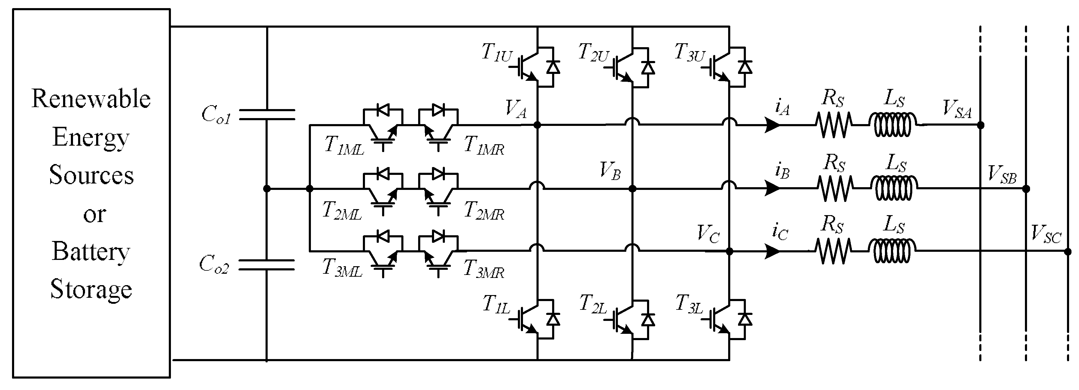
2. Structure of the Grid-Connected Systems with a T-Type Three-Level

One of the critical parts of several grid-connected systems, such as storage systems, photovoltaics, and wind generators, is the inverter. This power electronic converter is essential for the adaptation of voltages and power control between generators, storage systems, and the grid. Due to the many advantages of multilevel inverters, they have been considered a very interesting option. The T-type three-level three-phase inverter is one of the typical solutions (industrial solutions already present modules that integrate the complete topology) [72,73,74,75,76]. Figure 1 shows the considered topology, where VSA, VSB, and VSC are the grid voltages. As can be seen in this figure, it consists of a classical three-phase two-level inverter but with three bidirectional switches that allow the outputs of the AC inverter to be connected to the capacitor’s middle point. This three-level T-type three-phase inverter is connected to the grid through inductors’ low-pass filters.
To obtain the model representing the inverter connected to the grid, Kirchhoff’s laws are considered. Following this methodology, it is possible to obtain the state space equations of this system (1), where LS and RS denote the inductance and resistance of the filter and the line between the inverter and the grid.
d d t [ i A i B i C ]     =   1 L S   [ R S 0 0 0 R S 0 0 0 R S ]     [ i A i B i C ]       1 L S [ 1 0 0 0 1 0 0 0 1 ]     [ V A V B V C ]     + 1 L S [ 1 0 0 0 1 0 0 0 1 ]     [ V S A V S B V S C ]  
where i A , i B , and i C are the inverter’s AC currents; L S and R S are the inductance and internal resistance of the inductors; V A , V B , and V C are the inverter’s AC voltages; and V S A , V S B , and V S C are grid voltages.
On the other hand, the AC voltages of the inverter (VA, VB, and VC) are a function of the state of switches and output DC voltage. These voltages can be mathematically expressed in a simplified form, as a function of those variables, assuming transistors as ideal components. So, considering the fact that the inverter’s AC output voltages can assume three specific values with which they will be related to three switching functions, these functions, represented by Gi, are expressed as follows (where i = 1, 2, 3):
G i = {   1         if     T i U     i s       ON                 T i M L + T i M R     a r e     OFF         T i L     i s     OFF 0.5           if     T i U     i s     OFF           T i M L + T i M R     a r e     ON           T i L   i s     OFF     0         if     T i U     i s     OFF           T i M L + T i M R     a r e     OFF       T i L     i s     ON
Using the previous equation, it is finally possible to obtain the inverter’s output AC voltages as expressed by (3).
[ V A V B V C ]     =     V o [ 1 0 0 0 1 0 0 0 1 ]     [ G 1 G 2 G 3 ]    
From the analysis of Equations (2) and (3), it can be concluded that a fault in one of the transistors will affect the phase connected to the inverter leg associated with that transistor. Thus, in order to ensure the proper operation of the inverter, the integration of a fault diagnosis algorithm that detects faults early is fundamental.
Many control systems have been proposed to control the grid-connected inverters associated with renewable sources or storage systems; one of the most used is the one based on a decoupled dq-frame current controller. Thus, the system model (1) in the dq-reference frame (4) is considered.
d d t [ i d i q ] = 1 L s [ R S ω ω R S ]   [ i d i q ] 1 L s [ 1 0 0 1 ]   [ v d v q ] + 1 L s [ 1 0 0 1 ]   [ v S d v S q ]
where i d and i q are the inverter’s AC currents in the dq frame, ω is the angular frequency, v d and v q are the inverter’s AC voltages in the dq frame, and v S d and v S q the grid voltages in the dq frame.
The control of the active and reactive powers injected into the grid by the T-type inverter is achieved by ensuring that the AC currents in the dq coordinates will track the desired references. Through the instantaneous PQ power theory [77,78], these currents can be related to active and reactive power as expressed by
[ P Q ]   =   [ v s d v s q v s q v s d ]   [ i d i q ]
However, taking into consideration that the d axis of AC currents is in synchrony with the same component of AC voltages ( V s q = 0 ), the previous relationship can be simplified to the form presented in (6).
[ P Q ]   =   [ v s d 0 0 v s d ]   [ i d i q ]
From the analysis of this last power relationship, it is possible to conclude that each of them is only dependent on each current component. Thus, the active power can be controlled through the id component, while the reactive power is controlled through the iq component. Usually, in PV generators, the reactive power is zero, and therefore iq should also be zero. This intends to ensure that all the power generated by PV panels will be transferred to the grid. This can be achieved by ensuring that the DC capacitor’s voltages are nearly constant and equal to a specific value. This can be achieved through the use of a proportional–integral (PI) compensator, which will be associated with the d component of the AC currents (with gains K p V , K i V ). In this way, the d component reference of the AC currents can be expressed by this PI compensator associated with the error of DC capacitor’s voltages (reference and measured capacitors voltages), expressed as follows:
i d     =     ( K p V + K i V s )     ( V D C ( v C o 1 + v C o 2 ) )
where K p V and K i V are the proportional and integer gains of the PI regulator, i d is the component d of the AC current reference, and V D C is the inverter capacitor’s voltage reference.
As verified by (6), since the active and reactive powers are controlled by each of the dq current components, the inverter will be controlled by an inner decoupled current controller. This inner current controller, which considers the d and q components of the AC currents, will be controlled by two PI compensators in the SRF, defining the dq voltage components of the inverter. In this way, it will be possible to obtain the following control laws:
{ v d   =   ( K p I + K i I s ) (   i d * + i d )   +   ω L S   i q   +   v s d v q   =   ( K p I + K i I s ) (   i q * + i q )     ω L S   i d   +   v s q  
where K p I and K i I are the proportional and integer gains of the PI regulators used for the inner current controller.

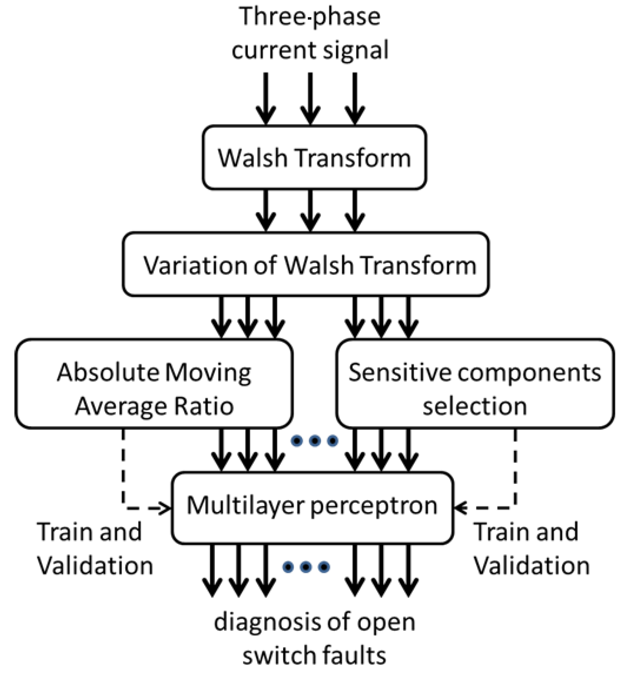
3. Fault Detection and Diagnosis Method

One of the important factors that can affect the reliability of grid-connected inverters is a fault in one of the controlled power semiconductors. As mentioned earlier, PV inverters contribute to 37% of overall unscheduled maintenance events [12]. On the other hand, it has been found that the most fragile components in power converters are semiconductor power devices [13]. Therefore, several methods have focused on the detection and diagnosis of open-transistor faults but with an emphasis on permanent faults. Often, these types of faults start with intermittent and incipient behavior. Initially, these faults are non-critical, but over time, they become permanent. In this way, incipient and intermittent faults can lead to irreversible deterioration. So, early detection can be considered important in order to ensure that the system maintains its reliability over time.
The method proposed in this paper for the detection and diagnosis of incipient and intermittent open-transistor faults, whose structure is presented in Figure 2, has several steps. The first part is the acquisition of the inverter’s AC currents, which are obtained using a sampling procedure. No additional sensors are needed, as they are already also required for the control system. Thus, the same sensors can be used. After this process, the acquired signals will be used with the Walsh transform to obtain a set of features that will define the characteristics of the faults. Finally, these signal features will be used by a multilayer perceptron (MLP) model to identify and diagnose the faulty transistor. This proposed fault detection and diagnosis method, in which the main structure is based on the Walsh transform combined with a multilayer-perceptron-based classifier, will also be designated by its abbreviation WT-MLT. As mentioned in the introduction, the adoption of neural networks was due to the fact that they are especially well adapted for pattern recognition problems [63,64,65]. Thus, since in this case, the purpose is to identify specific characteristics from the Walsh transform that are related to transistor faults, this adoption seems natural. In fact, as will be seen in the presented tests, this adoption led to very accurate results.

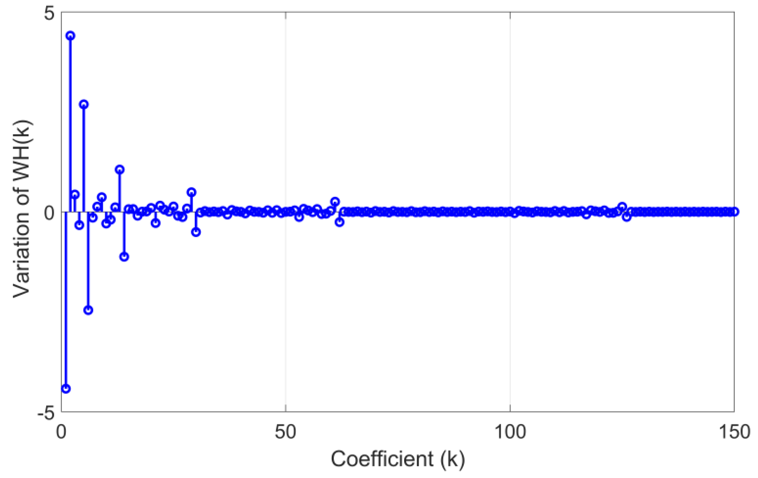
3.1. Feature Extraction Using Walsh Transform

The Walsh transform has been widely used in signal processing [79,80,81]. It is a generalized class of Fourier transform and is based on Walsh functions, which consist of the trains of square pulses with states +1 or −1. In harmonic analysis, Walsh functions create an orthogonal set of functions that can represent any discrete function. For a discrete function f(i) (i = 0, 1, …, N − 1), where N is the number of current samples, the Walsh transform (WH(k)) can be represented by
W H ( k ) = 1 2 p i = 0 N 1 f ( i ) H p + 1 ( k , i )
where 2p+1 < N < 2p, p ∈ N, k = 0, 1,…, 2p−1 and Hp+1(k,i) is the (k,i) input parameters of the Walsh function, Hp+1. The parameter p is the vector dimension of the Walsh transform. The Hp+1 can be calculated recursively using (10), where H1 = [1].
H p + 1 = [ H p H p H p H p ]
Considering the window p, and the window size N, the variation in the Walsh transform (ΔWH(k)) can be calculated by
Δ W H n ( k ) = W H n ( k ) W H n 1 ( k )
Considering the different fault scenarios, all coefficients of ΔWH(k) are calculated in order to find the coefficients of WH(k) that are most sensitive to a faulty condition. The most sensitive coefficients are the features that are used as inputs to the neural network.
To extract the signal features of ΔWH(k), the absolute average ratio using the most sensitive coefficients (MSC) is determined, as presented in (12) to (14).
M A = k = 0 M S C   Δ W H n ( k ) N
A M A n = k = 0 M S C   | Δ W H n ( k ) | N
A M A R n = M A n A M A n
where MAn is the moving average of ΔWH(k), and AMAn and AMARn are the absolute moving average and the absolute moving average ratio ΔWH(k), respectively.
The feature vector input in the neural network for the three-phase currents is defined by
[ A M A R n A A M A R n B A M A R n C Δ W H n A Δ W H n B Δ W H n C ]

3.2. Diagnosis with Artificial Neural Network

For the detection and diagnosis of open-transistor faults, a multilayer perceptron (MLP) is used, which is a class of feedforward artificial neural networks (ANNs) [82,83,84]. Through the learning process, this architecture can classify the type of fault for each input feature vector. The structure of the ANN used is shown in Figure 3, which has one input layer, two hidden layers, and one output layer.
For each three-phase current signal, the input of the MLP includes the absolute moving average ratio (AMARn) and the first 30 sensitive coefficients of ΔWHn(k), giving a total of 31 input parameters for each phase. Considering the 3 phases, as the feature vector totals 93 parameters, the ANN has 93 neurons in its input layer. The output layer represents the diagnostic results indicating whether or not a fault exists and what type of fault has occurred. Each neuron in the ANN output layer is associated with a fault type. As it is intended to identify 16 types of occurrences (1 healthy and 15 fault types), it is necessary for the ANN to have 16 neurons in its output layer. The number of hidden layers and the number of neurons in each of these layers are defined based on the minimization of the cost function used.
The scaled conjugate gradient is used to minimize the cross-entropy function. To evaluate how well the network predictions correspond to the target classification, the cross-entropy loss (13) is used. This type of function is used when true labels are one-hot-encoded, as happens in the proposed approach at the output to distinguish each fault.
L C E = i = 1 M t i log ( p i )
The parameter M corresponds to the number of fault types, ti is the truth label, and pi is the SoftMax probability for the ith fault. In MLP Training, the early stopping criterion is used when the validation error starts increasing.

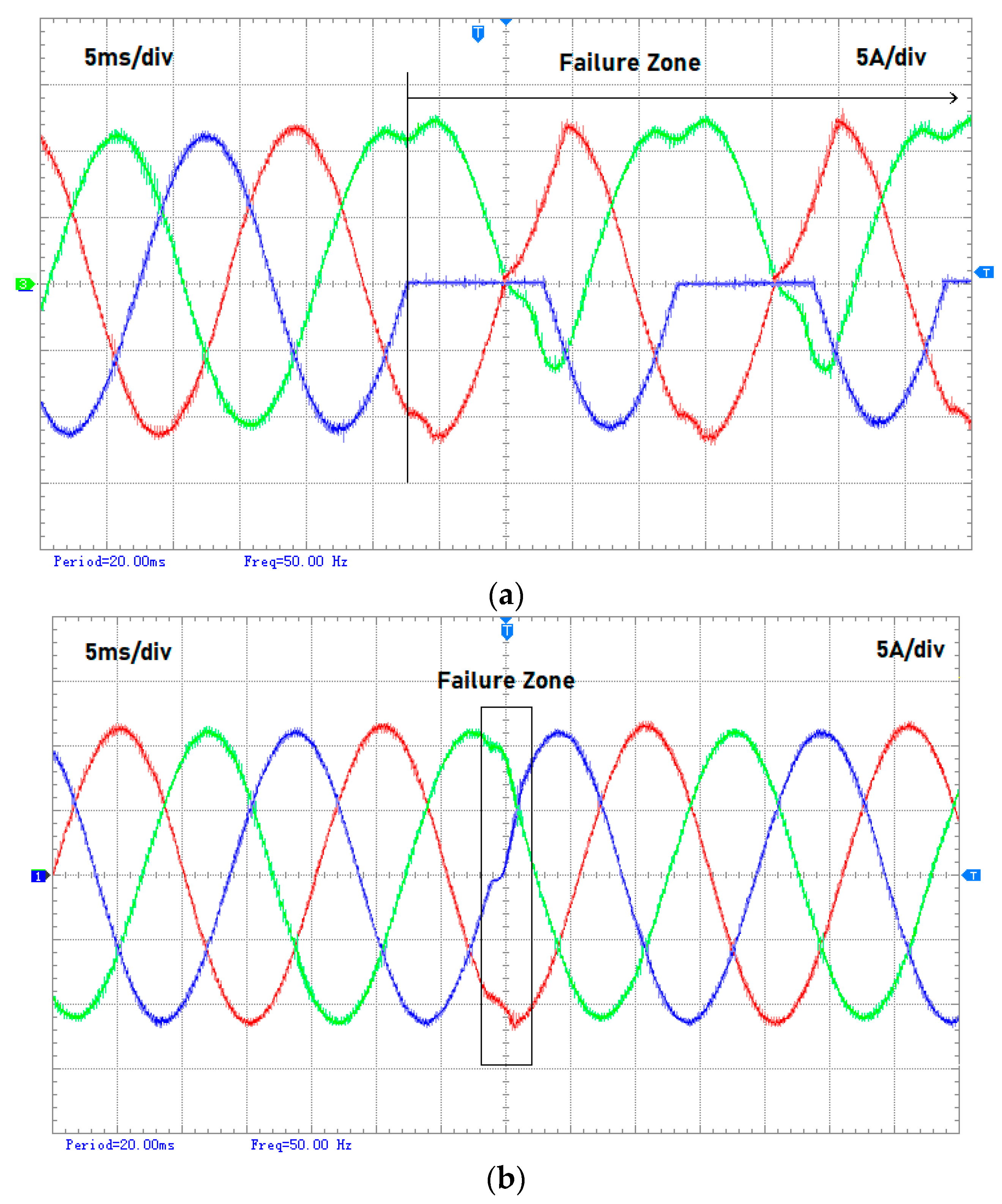
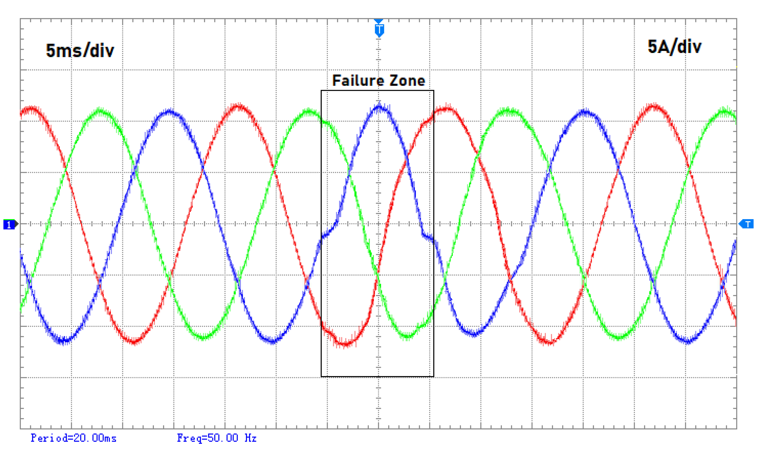
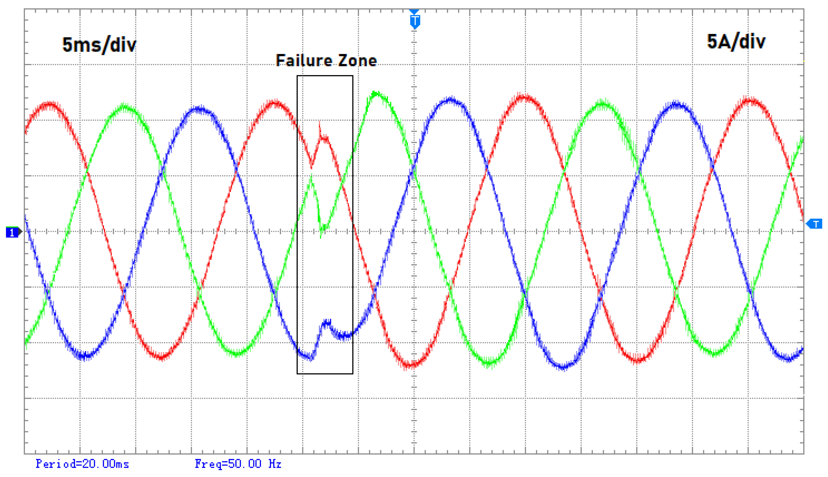
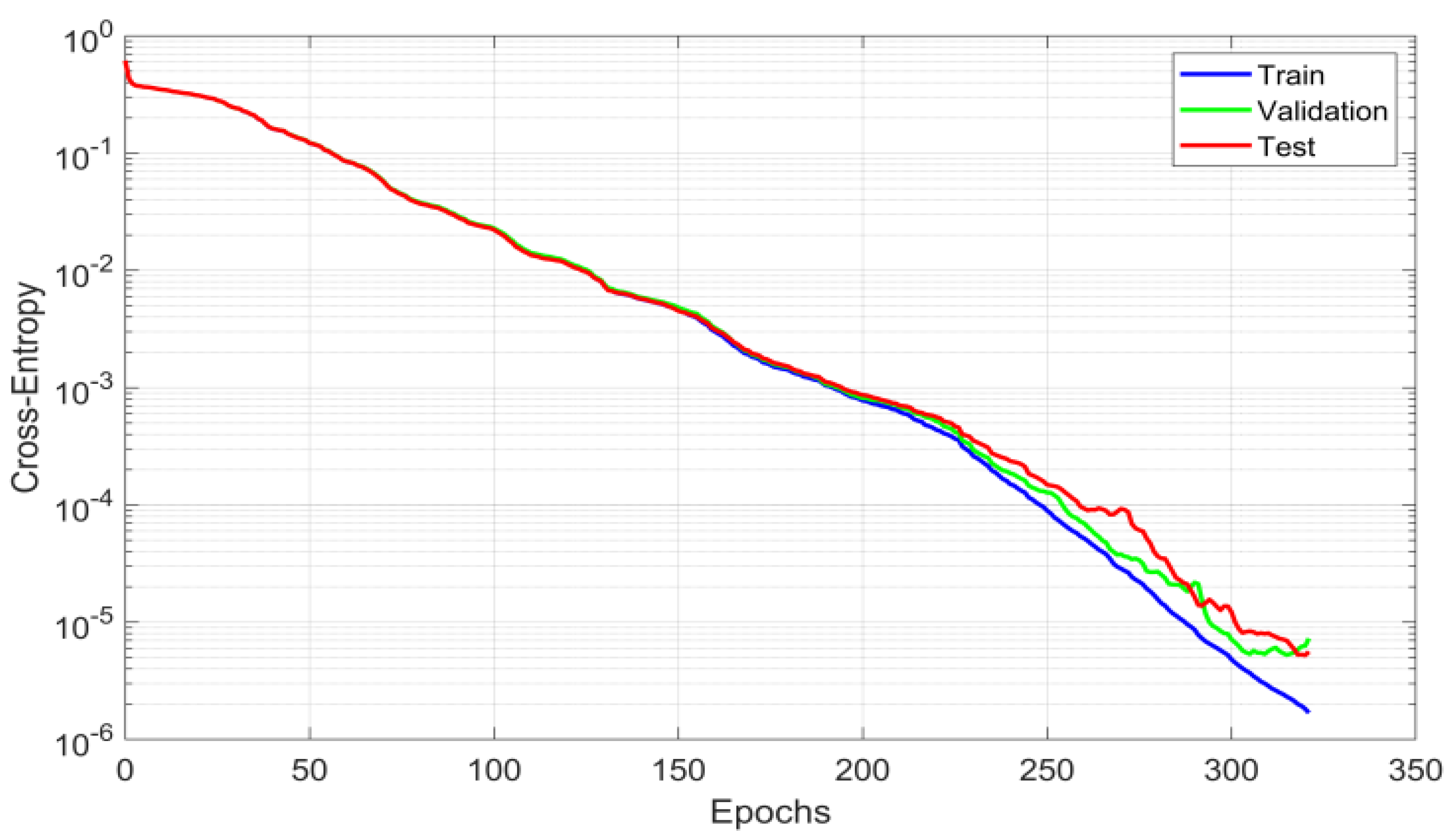
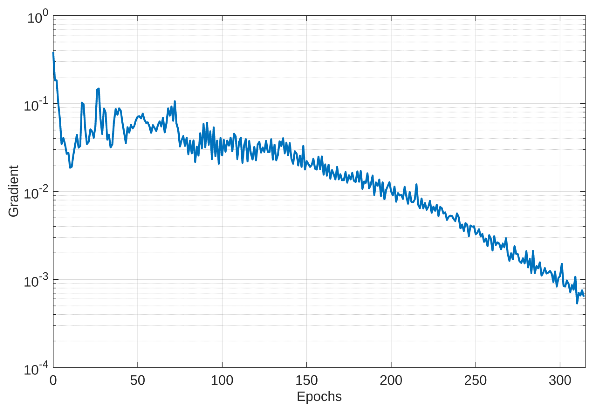
4. Results of Experimental Tests

The capabilities of the proposed WT-MLT method to detect incipient and intermittent inverter open-transistor faults were tested through the use of a laboratory prototype, using a commercial inverter module, namely the 12MBI75VN-120-50 module from Fuji Electric, Tokyo, Japan. The inverter was controlled using a dSPACE controller, and the open-transistor faults were implemented through the inhibition of transistor gate signals. The parameters of this experimental system are listed in Table 1.
The inverter was connected to the low-voltage laboratory grid. The three-phase currents were acquired with a sampling frequency of 200 kHz. Since the operating frequency of the inverter’s three-phase currents was 50 Hz, the number of samples in each period was 4000, which corresponded to the current window size N. As described before in the description of the proposed approach (Figure 2), after the acquisition of these currents, the Walsh transform was applied. Based on the current window size, the dimension of the vector WHn, p, was 4096. Under normal conditions, the value of the variation in the Walsh transform coefficients ΔWH(k) was approximately zero. Whenever a fault occurred, the vector of the Walsh transform, WH(k), presented some variations, and thus ΔWH(k) would also change. Figure 4 shows the variation in ΔWH(k) for the most sensitive coefficients in an incipient and intermittent fault in transistor T1U (in this case, the one presented in Figure 5b). From this result, it was possible to infer that ΔWH(k) was considerable for the first 30 coefficients. This aspect was also verified for the other tests performed. Since for each type of fault, a different pattern in ΔWH(k) appeared, those first 30 coefficients were considered as the features in the fault diagnosis method (MSC = 30).
As mentioned earlier, the purpose of the proposed methodology was to ensure that whenever an open-transistor fault appeared, the output of the detection algorithm would change its value. To investigate the difficulty in the detection of open-transistor intermittent and incipient faults, first, a converter with a permanent fault was tested. The result of this test for a permanent fault in transistor T1U is presented in Figure 5a. After analyzing these waveforms, it was found that the half-positive semicycle practically remained at zero, introducing an important DC component. However, in the case of an incipient and intermittent fault, the impact was very different. Figure 5b shows the same fault but with a duration of only 2 ms in one of the cycles. In this case, the impact on the current waveforms was minimal, making it difficult to see. The results of another test are presented in Figure 6, but in this case, they are for an intermittent fault in the transistors of the middle leg (T2ML and T2MR). The waveforms again show that the impact of the fault is very low and intermittent. Another incipient and intermittent fault for the upper transistor (T2U) was realized, but in this case, the start of the fault did not match the beginning of the semicycle. The result of this test can be seen in Figure 7. As shown in this figure, the pattern changes are a little bit more evident, although still with a reduced impact. One fact evident from these laboratory results is that, for this multilevel inverter connected to the grid with the widely used decoupled dq-frame current controller, the impact of these faults on the waveforms of the inverter AC currents is very tenuous. Thus, this indicates a very different behavior when compared with a permanent open-transistor fault in which the impact is much more visible and easier to detect.
A set of experimental tests were performed in order to assess the performance of the proposed WT-MLT fault detection and diagnosis algorithm. Table 2 presents the details and results obtained from these tests. The experimental data were divided into training, validation, and testing datasets. However, one of the important aspects was how to assess the quality of the training set. In machine learning applications, dataset preparation and data transformation are important tasks. The datasets were prepared to ensure their quality and the correctness of the model training. Data normalization was taken into account avoiding some of the feature values overweighting others. This is the case of the absolute moving average ratio in the feature vector described in (11). From the normalized dataset, the data were randomly divided into 60% for training and 20% for testing and validation [85]. For each transistor state, we had 32 training data, 11 test data, and 11 validation data (Table 2). The training data were balanced by oversampling the data of those transistor states less represented. The training set was used for learning to find the optimal weights of the model. The validation set was used to tune the number of hidden units of the model, determining the stop criterion for the scaled conjugate gradient backpropagation algorithm [86]. The conjugate gradient methods have many advantages in real numerical experiments, such as fast convergence and low memory requirements. Although the conjugate gradient method does not require the calculation of second derivatives, it has a quadratic convergence property [87]. The performance of the trained model was assessed using the test set. For the testing condition, the intermittent condition was also considered, i.e., a fault in one cycle, no fault during several cycles, and a fault again in one cycle. Table 2 lists the training and testing details used to test the capability of the proposed WT-MLT method. It is worth mentioning that the results presented in Table 2 are only associated with the faults in leg 1. However, there were also other tests associated with the other legs, the results being similar. For each condition of the transistor states, 96 different tests were used for training. These tests were performed for different AC current amplitudes and fault durations of the inverter. In MLP training, the early stopping criterion was obtained at epoch 315 with a cross-entropy value of 5.258 × 10⁻⁶. In the training algorithm, the sigma parameter that determined the weight change for the second derivative approximation during the training process had the value of 5 × 10⁻⁵. During the same process, the lambda parameter for regulating the indefiniteness of the Hessian value was 5 × 10⁻⁷. Figure 8 shows the cross-entropy loss over epochs for the training, validation, and testing datasets, and Figure 9 shows the correspondent gradient variation. It can be observed that the MLP model presents good convergence behavior, showing no sign of over- or under-fitting. This type of model with adaptive features and more than one output has a lower computational cost in its learning stage when compared to the models based on SVM or neuro-fuzzy theories, making it highly applicable.

5. Discussion

A fundamental aspect associated with the algorithms developed for the detection of transistor faults is regarding their performance. Moreover, since a method is proposed that is based on an algorithm that has the capability to learn, their validation and comparison with other approaches are very important. With this in mind, the proposed approach was compared with other advanced methods, such as the support vector machine (SVM) and the artificial neural network with multiresolution analysis (ANN-MRA). However, to ensure a fair comparison of the performance of the proposed method and other approaches, the same data were used for all of them (as previously mentioned, the data obtained from experimental tests). The results of the fault classification accuracy of the proposed WT-MLT and other methods are presented in Table 3. After analyzing these results, it was possible to conclude that all the methods could successfully diagnose incipient and intermittent open-transistor faults. However, for the proposed WT-MLT method, the accuracy was better in all tests. The SVM revealed the worst results. It was also found that the detection of a fault in the upper or lower transistors was more precise. The main weakness of the WT-MLT method was only for faults with a duration of less than 1 ms. In fact, for these faults with such a short time duration, the WT-MLT method was not able to detect them. Regarding the middle transistors, the accuracy was a little lower. In this case, the method had more difficulty in detecting faults that occurred with a duration of less than 2 ms. Another aspect that was also tested was the processing time associated with each of the methods. This aspect is very important for the practical implementation of the system, especially if it is intended for the continuous online fault detection and diagnosis of the transistors of the converter. From these tests, it was revealed that, on average, the WT-MLT approach presented a computational cost 10 times lower than the ANN-MRA and 25 times lower than the SVM. This also confirms that the proposed approach can be very convenient in real-time applications.

6. Conclusions

One of the fundamental aspects of the reliability of PV generators is the early detection of faults in the power electronic converters associated with them. Thus, this paper addressed the problem of the detection of open-transistor faults in inverters at an early stage, which usually precedes a permanent failure. So, in accordance with this purpose, a fault detection and diagnosis algorithm for incipient and intermittent inverter open-transistor faults was proposed. Since not many works addressed this important aspect, this novel approach can be considered as a step forward. Due to the very high difficulty in the detection of this kind of fault, the proposed method is based on an intelligent algorithm. The inverter that was considered had a three-level T-type three-phase topology, which is commonly applied to grid-connected applications such as renewable generators and battery storage systems. In order to ensure a fast and accurate method, the use of the Walsh transform was proposed. This proposal had the purpose of obtaining signals with detailed information that exist in line currents and are associated with incipient and intermittent open-transistor faults. One aspect that the use of the Walsh transform showed is that the process of training and testing was very fast. The algorithm developed using the proposed WT-MLT approach for the detection of incipient and intermittent open-transistor faults was tested through the use of a laboratory prototype. The results of several tests for different injected power levels and different fault times were presented. Another aspect that was verified was the validation and performance of the proposed approach. In line with this, a comparative study with other methods was carried out, namely the support vector machine (SVM) and the artificial neural network with multiresolution analysis (ANN-MRA). From this comparative study, it was possible to see that the proposed approach was the one that led to the best results. For the worst condition, namely a fault in the inner transistors, the proposed approach had an accuracy of 84%, while for the SVM, this was only 75%. Another aspect that was tested was the processing time, which is critical for continuous diagnosis in real-time applications. From the comparative study of the processing times between all the methods, it was possible to see that, on average, the WT-MLT approach presented a computational cost 10 times lower than the ANN-MRA and 25 times lower than the SVM. This shows the interesting capability of the proposed approach regarding real-time applications. Another aspect of this work is regarding future work. Due to the success of this kind of approach and the importance of the early detection of these failures in order to ensure the reliability of the system and to avoid unscheduled stops, this method must be adapted and tested in other power converter topologies. Another aspect is regarding the use of a deep learning approach. However, one important aspect that must also be taken into account is that this type of network requires a huge volume of data.

Author Contributions

Methodology, V.F.P., J.Y., T.T., L.L. and I.F.; software, T.G.A.; validation, D.F. and J.F.M.; investigation, T.G.A., V.F.P., A.C., J.Y., T.T., L.L. and I.F.; resources, D.F.; data curation, D.F.; writing—original draft, V.F.P.; writing—review & editing, T.G.A., A.C. and J.F.M.; Visualization, A.C. and J.F.M.; supervision, V.F.P. All authors have read and agreed to the published version of the manuscript.

Funding

This research was funded by national funds through FCT-Fundação para a Ciência e a Tecnologia, under projects UIDB/50021/2020 and UIDB/00066/2020.

Data Availability Statement

Not applicable.

Conflicts of Interest

The authors declare no conflict of interest.

References

  1. Milligan, M.; Frew, B.; Kirby, B.; Schuerger, M.; Clark, K.; Lew, D.; Denholm, P.; Zavadil, B.; O’Malley, M.; Tsuchida, B. Alternatives No More: Wind and Solar Power Are Mainstays of a Clean, Reliable, Affordable Grid. IEEE Power Energy Mag. 2015, 13, 78–87. [Google Scholar] [CrossRef]
  2. Ali Khan, M.Y.; Liu, H.; Yang, Z.; Yuan, X. A Comprehensive Review on Grid Connected Photovoltaic Inverters, Their Modulation Techniques, and Control Strategies. Energies 2020, 13, 4185. [Google Scholar] [CrossRef]
  3. Siu, K.K.M.; Ho, C.N.M. Generalized design approach of a family of grid-connected converters based on active virtual ground technique for single-phase AC microgrid applications. CPSS Trans. Power Electron. Appl. 2020, 5, 203–212. [Google Scholar] [CrossRef]
  4. Barrero-González, F.; Roncero-Clemente, C.; Milanés-Montero, M.I.; González-Romera, E.; Romero-Cadaval, E.; Husev, O.; Pires, V.F. Improvements on the Carrier-Based Control Method for a Three-Level T-Type, Quasi-Impedance-Source Inverter. Electronics 2019, 8, 677. [Google Scholar] [CrossRef] [Green Version]
  5. Zhang, C.W.; Zhang, T.; Chen, N.; Jin, T. Reliability modeling and analysis for a novel design of modular converter system of wind turbines. Reliab. Eng. Syst. Saf. 2013, 111, 86–94. [Google Scholar] [CrossRef] [Green Version]
  6. Madasamy, P.; Suresh Kumar, V.; Sanjeevikumar, P.; Holm-Nielsen, J.B.; Hosain, E.; Bharatiraja, C. A Three-Phase Transformerless T-Type- NPC-MLI for Grid Connected PV Systems with Common-Mode Leakage Current Mitigation. Energies 2019, 12, 2434. [Google Scholar] [CrossRef] [Green Version]
  7. Kan, S.; Ruan, X.; Huang, X.; Dang, H. Second Harmonic Current Reduction for Flying Capacitor Clamped Boost Three-Level Converter in Photovoltaic Grid-Connected Inverter. IEEE Trans. Power Electron. 2021, 36, 1669–1679. [Google Scholar] [CrossRef]
  8. Shawky, A.; Ahmed, M.; Orabi, M.; Aroudi, A.E. Classification of Three-Phase Grid-Tied Microinverters in Photovoltaic Applications. Energies 2020, 13, 2929. [Google Scholar] [CrossRef]
  9. Xu, S.; Zhang, J.; Huang, Y.; Jatskevich, J. Dynamic Average-Value Modeling of Three-Level T-Type Grid-Connected Converter System. IEEE J. Emerg. Sel. Top. Power Electron. 2019, 7, 2428–2442. [Google Scholar] [CrossRef]
  10. Amaral, T.G.; Pires, V.F.; Cordeiro, A.; Foito, D. A Skewness Based Method for Diagnosis in Quasi-Z T-Type Grid-Connected Converters. In Proceedings of the 8th International Conference on Renewable Energy Research and Applications, Brasov, Romania, 3–6 November 2019; pp. 131–136. [Google Scholar] [CrossRef]
  11. Zio, E. The Monte Carlo Simulation Method for System Reliability and Risk Analysis. In Springer Series in Reliability Engineering; Springer: Berlin/Heidelberg, Germany, 2013; Volume XIV, ISBN 978-1-4471-4587-5. [Google Scholar]
  12. Hu, K.; Liu, Z.; Yang, Y.; Iannuzzo, F.; Blaabjerg, F. Ensuring a Reliable Operation of Two-Level IGBT-Based Power Converters: A Review of Monitoring and Fault-Tolerant Approaches. IEEE Access 2020, 8, 89988–90022. [Google Scholar] [CrossRef]
  13. Yang, S.; Bryant, A.; Mawby, P.; Xiang, D.; Ran, L.; Tavner, P. An Industry-Based Survey of Reliability in Power Electronic Converters. IEEE Trans. Ind. Appl. 2011, 47, 1441–1451. [Google Scholar] [CrossRef]
  14. Spertino, F.; Amato, A.; Casali, G.; Ciocia, A.; Malgaroli, G. Reliability Analysis and Repair Activity for the Components of 350 kW Inverters in a Large Scale Grid-Connected Photovoltaic System. Electronics 2021, 10, 564. [Google Scholar] [CrossRef]
  15. Mullali Kunnontakath Puthiyapurayil, M.R.; Nadir Nasirudeen, M.; Saywan, Y.A.; Ahmad, M.W.; Malik, H. A Review of Open-Circuit Switch Fault Diagnostic Methods for Neutral Point Clamped Inverter. Electronics 2022, 11, 3169. [Google Scholar] [CrossRef]
  16. Khan, S.S.; Wen, H. A Comprehensive Review of Fault Diagnosis and Tolerant Control in DC-DC Converters for DC Microgrids. IEEE Access 2021, 9, 80100–80127. [Google Scholar] [CrossRef]
  17. Jaen-Cuellar, A.Y.; Elvira-Ortiz, D.A.; Osornio-Rios, R.A.; Antonino-Daviu, J.A. Advances in Fault Condition Monitoring for Solar Photovoltaic and Wind Turbine Energy Generation: A Review. Energies 2022, 15, 5404. [Google Scholar] [CrossRef]
  18. Gao, Z.; Cecati, C.; Ding, S.X. A Survey of Fault Diagnosis and Fault-Tolerant Techniques—Part I: Fault Diagnosis with Model-Based and Signal-Based Approaches. IEEE Trans. Ind. Electron. 2015, 62, 3757–3767. [Google Scholar] [CrossRef] [Green Version]
  19. Gao, Z.; Cecati, C.; Ding, S.X. A Survey of Fault Diagnosis and Fault-Tolerant Techniques—Part II: Fault Diagnosis with Knowledge-Based and Hybrid/Active Approaches. IEEE Trans. Ind. Electron. 2015, 62, 3768–3774. [Google Scholar] [CrossRef] [Green Version]
  20. Qiu, G.; Wu, F.; Chen, K.; Wang, L. A Robust Accuracy Weighted Random Forests Algorithm for IGBTs Fault Diagnosis in PWM Converters without Additional Sensors. Appl. Sci. 2022, 12, 2121. [Google Scholar] [CrossRef]
  21. Pires, V.F.; Cordeiro, A.; Foito, D.; Martins, J.F. Quasi-Z-Source Inverter With a T-Type Converter in Normal and Failure Mode. IEEE Trans. Power Electron. 2016, 31, 7462–7470. [Google Scholar] [CrossRef]
  22. Fahad, M.; Tariq, M.; Sarwar, A.; Modabbir, M.; Zaid, M.A.; Satpathi, K.; Hussan, M.R.; Tayyab, M.; Alamri, B.; Alahmadi, A. Asymmetric Multilevel Inverter Topology and Its Fault Management Strategy for High-Reliability Applications. Energies 2021, 14, 4302. [Google Scholar] [CrossRef]
  23. He, J.; Yang, Q.; Wang, Z. On-line fault diagnosis and fault-tolerant operation of modular multilevel converters—A comprehensive review. CES Trans. Electr. Mach. Syst. 2020, 4, 360–372. [Google Scholar] [CrossRef]
  24. Abadi, M.B.; Mendes, A.M.S.; Cruz, S.M.A. Three-level NPC inverter fault diagnosis by the Average Current Park’s Vector approach. In Proceedings of the 2012 XXth International Conference on Electrical Machines, Marseille, France, 2–5 September 2012; pp. 1893–1898. [Google Scholar] [CrossRef]
  25. Zhang, Y. Current behavior-based open-switch fault on-line diagnosis of inverters in PMSM drive systems. Measurement 2022, 202, 111810. [Google Scholar] [CrossRef]
  26. Iglesias-Rojas, J.C.; Velázquez-Lozada, E.; Baca-Arroyo, R. Online Failure Diagnostic in Full-Bridge Module for Optimum Setup of an IGBT-Based Multilevel Inverter. Energies 2022, 15, 5203. [Google Scholar] [CrossRef]
  27. Cheng, Y.; Dong, W.; Gao, F.; Xin, G. Open-circuit fault diagnosis of traction inverter based on compressed sensing theory. Chin. J. Electr. Eng. 2020, 6, 52–63. [Google Scholar] [CrossRef]
  28. Zhang, W.; Wang, Z.; Li, X. Blockchain-based decentralized federated transfer learning methodology for collaborative machinery fault diagnosis. Reliab. Eng. Syst. Saf. 2022, 229, 108885. [Google Scholar] [CrossRef]
  29. Ding, Y.; Jia, M.; Zhuang, J.; Cao, Y.; Zhao, X.; Lee, C.-G. Deep imbalanced domain adaptation for transfer learning fault diagnosis of bearings under multiple working conditions. Reliab. Eng. Syst. Saf. 2022, 230, 108890. [Google Scholar] [CrossRef]
  30. Park, C.H.; Kim, H.; Suh, C.; Chae, M.; Yoon, H.; Youn, B.D. A health image for deep learning-based fault diagnosis of a permanent magnet synchronous motor under variable operating conditions: Instantaneous current residual map. Reliab. Eng. Syst. Saf. 2022, 226, 108715. [Google Scholar] [CrossRef]
  31. Zuo, L.; Xu, F.; Zhang, C.; Xiahou, T.; Liu, Y. A multi-layer spiking neural network-based approach to bearing fault diagnosis. Reliab. Eng. Syst. Saf. 2022, 225, 108561. [Google Scholar] [CrossRef]
  32. Zhang, Y.; Wang, X.; Yang, R. Incipient fault detection based on Just-in-time-learning and wavelet transform for DAB DC-DC converter. In Proceedings of the 33rd Chinese Control and Decision Conference, Kunming, China, 22–24 May 2021; pp. 6245–6250. [Google Scholar] [CrossRef]
  33. Baghli, M.; Delpha, C.; Diallo, D.; Hallouche, A.; Mba, D.; Wang, T. Three-Level NPC Inverter Incipient Fault Detection and Classification using Output Current Statistical Analysis. Energies 2019, 12, 1372. [Google Scholar] [CrossRef] [Green Version]
  34. Rodriguez-Urrego, L.; García, E.; Quiles, E.; Correcher, A.; Morant, F.; Pizá, R. Diagnosis of Intermittent Faults in IGBTs Using the Latent Nestling Method with Hybrid Coloured Petri Nets. Math. Probl. Eng. 2015, 2015, 130790. [Google Scholar] [CrossRef] [Green Version]
  35. Freire, N.M.; AEstima, J.O.; Marques Cardoso, A.J. Open-Circuit Fault Diagnosis in PMSG Drives for Wind Turbine Applications. IEEE Trans. Ind. Electron. 2013, 60, 3957–3967. [Google Scholar] [CrossRef]
  36. Mendes, A.M.S.; Bandarabadi, M.; Cruz, S.M.A. Fault diagnostic algorithm for three-level neutral point clamped AC motor drives, based on the average current Park’s vector. IET Power Electron. 2014, 7, 1127–1137. [Google Scholar] [CrossRef]
  37. Estima, J.O.; Marques Cardoso, A.J. A New Algorithm for Real-Time Multiple Open-Circuit Fault Diagnosis in Voltage-Fed PWM Motor Drives by the Reference Current Errors. IEEE Trans. Ind. Electron. 2013, 60, 3496–3505. [Google Scholar] [CrossRef]
  38. Gonzalez-Jimenez, D.; del-Olmo, J.; Poza, J.; Garramiola, F.; Madina, P. Data-Driven Fault Diagnosis for Electric Drives: A Review. Sensors 2021, 21, 4024. [Google Scholar] [CrossRef]
  39. Liu, S.; Jiang, B.; Mao, Z.; Ma, Y. Observer based fault estimation for inverter devices of traction systems with disturbance. In Proceedings of the Chinese Automation Congress (CAC), Jinan, China, 20–22 October 2017; pp. 2006–2010. [Google Scholar] [CrossRef]
  40. Wang, B.; Li, Z.; Bai, Z.; Krein, P.T.; Ma, H. A Voltage Vector Residual Estimation Method Based on Current Path Tracking for T-Type Inverter Open-Circuit Fault Diagnosis. IEEE Trans. Power Electron. 2021, 36, 13460–13477. [Google Scholar] [CrossRef]
  41. Xiao, C.; Wu, W.; Gao, N.; Koutroulis, E.; Chung, H.S.; Blaabjerg, F. Fault Diagnosis and Reconfiguration for H6 Grid-Tied Inverter Using Kalman Filter. In Proceedings of the 47th Annual Conference of the IEEE Industrial Electronics Society (IECON 2021), Toronto, ON, Canada, 13–16 October 2021; pp. 1–5. [Google Scholar] [CrossRef]
  42. Youssef, A.B.; El Khil, S.K.; Belkhodja, I.S. Open-circuit fault diagnosis and voltage sensor fault tolerant control of a single phase pulsed width modulated rectifier. Math. Comput. Simul. 2017, 131, 234–252. [Google Scholar] [CrossRef]
  43. Chen, J.-L.; Kuo, C.-L.; Chen, S.-J.; Kao, C.-C.; Zhan, T.-S.; Lin, C.-H.; Chen, Y.-S. DC-side fault detection for photovoltaic energy conversion system using fractional-order dynamic-error-based fuzzy Petri net integrated with intelligent meters. IET Renew. Power Gener. 2016, 10, 1318–1327. [Google Scholar] [CrossRef]
  44. Wu, Y.; Jiang, B.; Zhu, Z.; Zeng, Q. Data-driven based ToMFIR Design with Application to Incipient Fault Detection in High-speed Rail Vehicle Suspension System. In Proceedings of the Symposium on Fault Detection, Supervision and Safety for Technical Processes (SAFEPROCESS), Xiamen, China, 5–7 July 2019; pp. 645–650. [Google Scholar] [CrossRef]
  45. Karmacharya, I.M.; Gokaraju, R. Fault Location in Ungrounded Photovoltaic System Using Wavelets and ANN. IEEE Trans. Power Deliv. 2018, 33, 549–559. [Google Scholar] [CrossRef]
  46. Xiao, C.; Liu, Z.; Zhang, T.; Zhang, X. Deep Learning Method for Fault Detection of Wind Turbine Converter. Appl. Sci. 2021, 11, 1280. [Google Scholar] [CrossRef]
  47. Rajeswaran, N.; Thangaraj, R.; Mihet-Popa, L.; Krishna Vajjala, K.V.; Özer, Ö. FPGA Implementation of AI-Based Inverter IGBT Open Circuit Fault Diagnosis of Induction Motor Drive. Micromachines 2022, 13, 663. [Google Scholar] [CrossRef]
  48. Foito, D.; Martins, J.F.; Pires, V.F.; Maia, J. An Eigenvalue/Eigenvector 3D Current Reference Method for Detection and Fault Diagnosis in a Voltage Source Inverter. In Proceedings of the 35th Annual Conference of the IEEE Industrial Electronics Society (IECON), Porto, Portugal, 3–5 November 2009; pp. 195–199. [Google Scholar]
  49. Yuan, W.; Wang, T.; Diallo, D.; Delpha, C. A Fault Diagnosis Strategy Based on Multilevel Classification for a Cascaded Photovoltaic Grid-Connected Inverter. Electronics 2020, 9, 429. [Google Scholar] [CrossRef] [Green Version]
  50. Jin, G.; Wang, T.; Amirat, Y.; Zhou, Z.; Xie, T. A Layering Linear Discriminant Analysis-Based Fault Diagnosis Method for Grid-Connected Inverter. Mar. Sci. Eng. 2022, 10, 939. [Google Scholar] [CrossRef]
  51. Bouyeddou, B.; Harrou, F.; Taghezouit, B.; Sun, Y.; Hadj Arab, A. Improved Semi-Supervised Data-Mining-Based Schemes for Fault Detection in a Grid-Connected Photovoltaic System. Energies 2022, 15, 7978. [Google Scholar] [CrossRef]
  52. Hu, H.; Feng, F.; Wang, T. Open-circuit fault diagnosis of NPC inverter IGBT based on independent component analysis and neural network. Energy Rep. 2020, 6, 134–143. [Google Scholar] [CrossRef]
  53. Sarita, K.; Kumar, S.; Saket, R.K. OC fault diagnosis of multilevel inverter using SVM technique and detection algorithm. Comput. Electr. Eng. 2021, 96, 107481. [Google Scholar] [CrossRef]
  54. Chowdhury, D.; Villez, K. Qualitative trend analysis based on a mixed-integer representation. Comput. Chem. Eng. 2023, 170, 108109. [Google Scholar] [CrossRef]
  55. Hua, J.; Lu, L.; Ouyang, M.; Li, J.; Xu, L. Proton exchange membrane fuel cell system diagnosis based on the signed directed graph method. Power Sources 2011, 196, 14. [Google Scholar] [CrossRef]
  56. Gmati, B.; Jlassi, I.; El Khil, S.K.; Marques Cardoso, A.J. Open-switch fault diagnosis in voltage source inverters of PMSM drives using predictive current errors and fuzzy logic approach. IET Power Electron. 2021, 14, 1059–1072. [Google Scholar] [CrossRef]
  57. Hussain, I.; Khalil, I.U.; Islam, A.; Ahsan, M.U.; Iqbal, T.; Chowdhury, M.S.; Techato, K.; Ullah, N. Unified Fuzzy Logic Based Approach for Detection and Classification of PV Faults Using I–V Trend Line. Energies 2022, 15, 5106. [Google Scholar] [CrossRef]
  58. Yan, H.; Xu, Y.; Cai, F.; Zhang, H.; Zhao, W.; Gerada, C. PWM-VSI Fault Diagnosis for a PMSM Drive Based on the Fuzzy Logic Approach. IEEE Trans. Power Electron. 2019, 34, 759–768. [Google Scholar] [CrossRef]
  59. Nasser, A.R.; Azar, A.T.; Humaidi, A.J.; Al-Mhdawi, A.K.; Ibraheem, I.K. Intelligent Fault Detection and Identification Approach for Analog Electronic Circuits Based on Fuzzy Logic Classifier. Electronics 2021, 10, 2888. [Google Scholar] [CrossRef]
  60. Yang, F.; Xiao, D.Y. Review of SDG modeling and its application. Control Theory Appl. 2005, 22, 767–774. [Google Scholar]
  61. Tsai, D.; Wu, S.; Chiu, W. Defect detection in solar modules using ICA basis images. IEEE Trans. Ind. Inform. 2013, 9, 122–131. [Google Scholar] [CrossRef]
  62. Seshadrinath, J.; Singh, B.; Panigrahi, B. Vibration analysis based interturn fault diagnosis in induction machines. IEEE Trans. Ind. Inform. 2014, 10, 340–350. [Google Scholar] [CrossRef]
  63. Abiodun, O.I.; Jantan, A.; Omolara, A.E.; Dada, K.V.; Umar, A.M.; Linus, O.U.; Arshad, U.; Gana, U.; Kiru, M.U. Comprehensive Review of Artificial Neural Network Applications to Pattern Recognition. IEEE Access 2019, 7, 158820–158846. [Google Scholar] [CrossRef]
  64. Diniz, A.P.M.; Ciarelli, P.M.; Salles, E.O.T.; Coco, K.F. Long short-term memory neural networks for clogging detection in the submerged entry nozzle. Decis. Mak. Appl. Manag. Eng. 2022, 5, 154–168. [Google Scholar] [CrossRef]
  65. Ghosh, I.; Datta Chaudhuri, T. FEB-Stacking and FEB-DNN Models for Stock Trend Prediction: A Performance Analysis for Pre and Post COVID-19 Periods. Decis. Mak. Appl. Manag. Eng. 2021, 4, 51–84. [Google Scholar] [CrossRef]
  66. Martins, J.F.; Pires, V.F.; Lima, C.; Pires, A.J. Fault detection and diagnosis of grid-connected power inverters using PCA and current mean value. In Proceedings of the 38th Annual Conference on IEEE Industrial Electronics Society (IECON 2012), Montreal, QC, Canada, 25–28 October 2012; pp. 5185–5190. [Google Scholar] [CrossRef]
  67. Huang, Z.; Wang, Z.; Zhang, H. Multilevel feature moving average ratio method for fault diagnosis of the microgrid inverter switch. IEEE/CAA J. Autom. Sin. 2017, 4, 177–185. [Google Scholar] [CrossRef]
  68. Huang, Z.; Wang, Z.; Zhang, H. Multiple Open-Circuit Fault Diagnosis Based on Multistate Data Processing and Subsection Fluctuation Analysis for Photovoltaic Inverter. IEEE Trans. Instrum. Meas. 2018, 67, 516–526. [Google Scholar] [CrossRef]
  69. Hong, Y.-Y.; Wei, Y.-H.; Chang, Y.-R.; Lee, Y.-D.; Liu, P.-W. Fault detection and location by static switches in microgrids using wavelet transform and adaptive network-based fuzzy inference system. Energies 2014, 7, 2658–2675. [Google Scholar] [CrossRef] [Green Version]
  70. Ye, F.; Zhang, Z.; Chakrabarty, K.; Gu, X. Board-level functional fault diagnosis using multikernel support vector machines and incremental learning. IEEE Trans. Comput.-Aided Design Integr. Circuits Syst. 2014, 33, 279–290. [Google Scholar] [CrossRef]
  71. Sheibat-Othman, N.; Laouti, N.; Valour, J.; Othman, S. Support vector machines combined to observers for fault diagnosis in chemical reactors. Can. J. Chem. Eng. 2014, 92, 685–694. [Google Scholar] [CrossRef]
  72. Schweizer, M.; Kolar, J.W. Design and Implementation of a Highly Efficient Three-Level T-Type Converter for Low-Voltage Applications. IEEE Trans. Power Electron. 2013, 28, 899–907. [Google Scholar] [CrossRef]
  73. Ngo, V.-Q.-B.; Nguyen, M.-K.; Tran, T.-T.; Choi, J.-H.; Lim, Y.-C. A Modified Model Predictive Power Control for Grid-Connected T-Type Inverter with Reduced Computational Complexity. Electronics 2019, 8, 217. [Google Scholar] [CrossRef] [Green Version]
  74. Yin, Z.; Hu, C.; Luo, K.; Rui, T.; Feng, Z.; Lu, G.; Zhang, P. A Novel Model-Free Predictive Control for T-Type Three-Level Grid-Tied Inverters. Energies 2022, 15, 6557. [Google Scholar] [CrossRef]
  75. Bhattacharya, S.; Sharma, S.K.; Mascarella, D.; Joos, G. Subfundamental Cycle Switching Frequency Variation Based on Output Current Ripple Analysis of a Three-Level Inverter. IEEE J. Emerg. Sel. Top. Power Electron. 2017, 5, 1797–1806. [Google Scholar] [CrossRef]
  76. Chao, K.-H.; Chang, L.-Y.; Hung, C.-C. Fault Diagnosis and Tolerant Control for Three-Level T-Type Inverters. Electronics 2022, 11, 2496. [Google Scholar] [CrossRef]
  77. Brito, R.; Carvalho, A.; Gericota, M. A new three-phase voltage sourced converter laplace model. In Proceedings of the 9th International Conference on Compatibility and Power Electronics (CPE), Costa da Caparica, Portugal, 24–26 June 2015; pp. 160–166. [Google Scholar] [CrossRef]
  78. Akagi, H.; Inoue, S.; Yoshii, T. Control and performance of a transformerless cascade PWM STATCOM with star configuration. IEEE Trans. Ind. Appl. 2007, 43, 1041–1049. [Google Scholar] [CrossRef]
  79. Thompson, A. The Cascading Haar Wavelet Algorithm for Computing the Walsh–Hadamard Transform. IEEE Signal Process. Lett. 2017, 24, 1020–1023. [Google Scholar] [CrossRef] [Green Version]
  80. Wu, Y.; Yue, Q.; Li, F. More Functions with Three-Valued Walsh Transform from Linear Combinations. IEEE Commun. Lett. 2019, 23, 564–567. [Google Scholar] [CrossRef]
  81. Zheng, P.; Huang, J. Efficient Encrypted Images Filtering and Transform Coding with Walsh-Hadamard Transform and Parallelization. IEEE Trans. Image Process. 2018, 27, 2541–2556. [Google Scholar] [CrossRef]
  82. Jeong, S.; Lee, J. Modulation Code and Multilayer Perceptron Decoding for Bit-Patterned Media Recording. IEEE Magn. Lett. 2020, 11, 1–5. [Google Scholar] [CrossRef]
  83. Liao, S.; Jiang, X.; Ge, Z. Weakly Supervised Multilayer Perceptron for Industrial Fault Classification with Inaccurate and Incomplete Labels. IEEE Trans. Autom. Sci. Eng. 2022, 19, 1192–1201. [Google Scholar] [CrossRef]
  84. Guo, W.; Yang, Y.; Zhou, Y.; Tan, Y.; Wei, H.; Song, A.; Pang, G. Influence Area of Overlap Singularity in Multilayer Perceptrons. IEEE Access 2018, 6, 60214–60223. [Google Scholar] [CrossRef]
  85. Ripley, B.D. Pattern Recognition and Neural Networks; University of Oxford: Oxford, UK; Cambridge University Press: Cambridge, UK, 1996. [Google Scholar]
  86. Møller, M.F. A scaled conjugate gradient algorithm for fast supervised learning. Neural Netw. 1993, 6, 525–533. [Google Scholar] [CrossRef]
  87. Hagan, M.; Demuth, H.; Beale, M. Neural Netw. Design; PWS Publisher: Boston, MA, USA, 1996. [Google Scholar]
Figure 1. A typical solution for grid-connected renewable generators and storage systems in which a T-type three-phase inverter is used i A .
Energies 16 02668 g001
Figure 2. Structure of the proposed incipient WT-MLT fault diagnosis method.
Energies 16 02668 g002
Figure 3. MLP structure for current fault detection and diagnosis.
Energies 16 02668 g003
Figure 4. Change in Walsh transform coefficients in a fault condition in transistor T1U.
Energies 16 02668 g004
Figure 5. Experimental inverter three-phase currents: (a) for a permanent fault in transistor T1U; (b) for an intermittent fault in transistor T1U.
Energies 16 02668 g005
Figure 6. Experimental inverter three-phase currents for an intermittent fault in transistors T2ML and T2MR.
Energies 16 02668 g006
Figure 7. Experimental inverter three-phase currents for an intermittent fault in transistor T1U in which the start of the fault is not at the beginning of the semicycle.
Energies 16 02668 g007
Figure 8. Cross-entropy loss results over epochs.
Energies 16 02668 g008
Figure 9. Gradient variation over epochs.
Energies 16 02668 g009
Table 1. Parameters of the system with a T-type inverter.
ParametersValue
Grid RMS voltage110 V
Grid frequency50 Hz
Input DC voltage500 V
Transistor switching frequency20 kHz
Inductance10 mH
Internal resistance of the inductance0.1 Ω
DC capacitors1000 μF
Table 2. MLP training, testing, and validation details.
Transistor StatesTarget Output ValueTraining DataTesting DataValidation Data
No-fault100000963232
T1U010000963232
T1ML001000963232
T1MR000100963232
T1ML, T1MR000010963232
T1L000001963232
Table 3. Comparison between the proposed and other advanced methods regarding the fault classification accuracy.
Switches StatesSVMANN-MRAProposed WT-MLT
No-fault96%100%100%
T1U79%87%90%
T1ML76%81%84%
T1MR76%82%84%
T1ML, T1MR75%84%84%
T1L80%88%90%
Disclaimer/Publisher’s Note: The statements, opinions and data contained in all publications are solely those of the individual author(s) and contributor(s) and not of MDPI and/or the editor(s). MDPI and/or the editor(s) disclaim responsibility for any injury to people or property resulting from any ideas, methods, instructions or products referred to in the content.

