Review

Transient Stability Analysis and Enhancement Techniques of Renewable-Rich Power Grids

Department of Electrical Engineering, School of Electronic and Electrical Engineering, Kyungpook National University, Daegu 41566, Republic of Korea
*
Author to whom correspondence should be addressed.
Energies 2023, 16(5), 2495; https://doi.org/10.3390/en16052495
Submission received: 31 December 2022 / Revised: 20 February 2023 / Accepted: 3 March 2023 / Published: 6 March 2023
(This article belongs to the Special Issue Studies on Power System Dynamics and Stability)

Abstract

:
New techniques and approaches are constantly being introduced to analyze and enhance the transient stability of renewable energy-source-dominated power systems. This review article extensively discusses recent papers that have proposed novel and innovative techniques for analyzing and enhancing the renewable source-dominated power system’s transient stability. The inherent low-inertia characteristics of renewable energy sources combined with fast-acting power electronic devices pose new challenges in power systems. Different stability concerns exist for grid-following and subsequent grid-forming converter/inverter connections to power grids; hence, distinct solutions for enhancing the transient stability have been devised for each. Moreover, the fundamental concepts and characteristics of converter/inverter topologies are briefly discussed in this study. Recent discussions and reviews of analysis and enhancement techniques in transient stability could lead to new ways to solve problems in power systems that rely primarily on renewable energy sources.

1. Introduction

Owing to environmental concerns, the power systems of most nations are undergoing a transition from the use of conventional energy sources (e.g., coal, oil, and gas) to greater utilization of non-conventional energy sources (e.g., solar and wind) with the aid of advanced power electronic P E converter/inverter devices and their controls [1,2,3,4,5]. Many countries have established the goal of generating a substantial portion of their electrical energy from renewable energy sources R E S to preserve the environment [6,7,8]. With this transition, the system dynamics will no longer be described in terms of the torque-speed correlations of synchronous machines; instead, the voltage-current characteristics of converter-based generation are predominant [9]. Moreover, the transition process impacts the steady-state and transient operations of the power system owing to the reduced available inertia and the change in system oscillations caused by the fast-acting P E devices integrated into the system [10].
P E -based converters/inverters are widely employed for deploying renewable energy sources in distribution systems [11,12,13]. One of the essential components of a power converter/inverter is the voltage source converter V S C or voltage source inverter V S I , which converts corresponding AC and DC signals by utilizing coordinate transformations. Many experts and researchers have proposed control strategies to enhance their dependability, effectiveness, and security [14,15,16,17]. Vector-current controls V C C , developed in a synchronous rotating reference frame, are a standard control strategy for grid-connected V S C / V S I s. These components allow linear control techniques to indirectly regulate real and reactive powers by managing direct and quadrature ( d q ) axis line currents I d , I q independently [18,19,20]. As the currents along the dq axis must be in phase with the grid voltage, the phase angle required by the Park transformation must be appropriately retrieved from the grid via a phase-locked loop P L L [21,22]. This configuration of V S C / V S I causes the converter/inverter to follow the grid’s regulated voltage and frequency. It is therefore referred to as a grid-following G F L   R E S connection. This is the first generation of a P E -based R E S connection strategy to generate or track the maximum output power to the grid [23]. However, the P L L requirement delays the transient response and, in some instances, may cause instability in weak grids [24,25,26,27]. This has led to the second generation of P E -based R E S connection strategies, known as grid-forming G F M , which are intended to provide capabilities comparable to those of synchronous generators S G s [28,29,30].
G F M possesses a wide range of inherent properties, including black start abilities, enhanced synchronization performance in weak grids, inertia, and frequency support capability, which contains a better rate of change of frequency R o C o F and frequency nadir [31,32,33]. Similar to synchronous machines, synchronization to the grid can be performed at the start of the G F M operation without installing any specific synchronization mechanism. A G F M often possesses several internal control loops, including inner current and voltage loops, active and reactive power controller loops, virtual impedance loops, etc. The active power controller A P C and the reactive power controller R P C regulate the voltage magnitude and frequency at the point of common coupling P C C and, thus, the voltage phase [28]. Consequently, the inner cascaded controller structure was designed to handle the magnitude dynamically and the angle of the voltage phasor to perform grid synchronization and grid support during disturbances [23], and the effect of these internal cascade loops on the performance of G F M was investigated in [34]. The works in [34,35] demonstrated the benefits of G F M control in inertial support for megawatt-scale projects, including wind farms and battery energy storage systems. With the growing interest in G F M technology, several projects and resources have been launched with a focus on exploring the merging of this new technology with older ones. It is anticipated that they will all be connected to the same power grid [35,36,37,38]. Despite the modeling, control, and technological advancements, G F M   R E S integration is still in its infancy for large power system applications. Consequently, modeling tools, control processes, and challenges remain largely unknown. This has been the primary focus of many scholars over the past few years [30,39,40,41,42].
In the past, due to the insignificant contribution of R E S to power generation, it was normal practice for many power grids to disconnect R E S during system disruptions in order to maintain system stability. However, the disconnection of R E S could cause the modern grids to become unbalanced, thereby threatening system stability owing to the high proportion of R E S [43]. Hence, transient stability analysis and enhancement techniques for the newly formed grid with G F L and G F M   R E S connection strategies would be an open research challenge.
The transient stability of a power grid is the system’s capability to maintain synchronization among generators and achieve adequate steady-state operating circumstances in the face of significant disruptions, which include the loss of generating units, significant load shifts, and line faults [44]. Transient stability is critical to the secure and reliable operation of the power system because it ensures that the system can recover from disturbances without collapsing or cascading into a blackout. Similarly, the newly formed R E S -dominated grid’s transient stability requirements are the same despite their lower inertia and short-circuit current capabilities. Although control interactions differ from conventional grids, the same stability evaluation tools can be employed to investigate transient stability [45,46,47].
As it is well known that converters/inverters are versatile and adaptive, they can be configured to emulate the dynamic properties of S G s. However, P E -based energy conversion devices have limited thermal capacities and discharge a high current during the transient phase, potentially damaging electronic device components [48]. Thus, fault ride-through control strategies are required to limit the current flow through the P E -based devices during the transient phase [49,50]. Nonetheless, these fault ride-through control strategies turn out power imbalances between input-output active powers and increase the acceleration area, resulting in a reduced stability margin. Hence, adequately designed efficient control techniques and algorithms are developed independently for G F L and G F M connection strategies to improve the transient resilience of R E S -dominated power grids. This paper offers a comprehensive literature assessment of contemporary studies discussing innovative and inventive strategies for analyzing and strengthening the R E S -dominated power grid’s transient stability.
The rest of the paper is structured as follows: Section 2 discusses the classification of R E S connections to grids, with a detailed explanation of G F L and G F M strategies. In Section 3, voltage source converter/inverter topologies are given with the generalized controller structure. The transient stability analysis techniques are discussed in Section 4. In Section 5, transient stability enhancement techniques for G F L and G F M strategies are presented and compared. Finally, Section 6 concludes the investigation and outlines recommendations for further research.

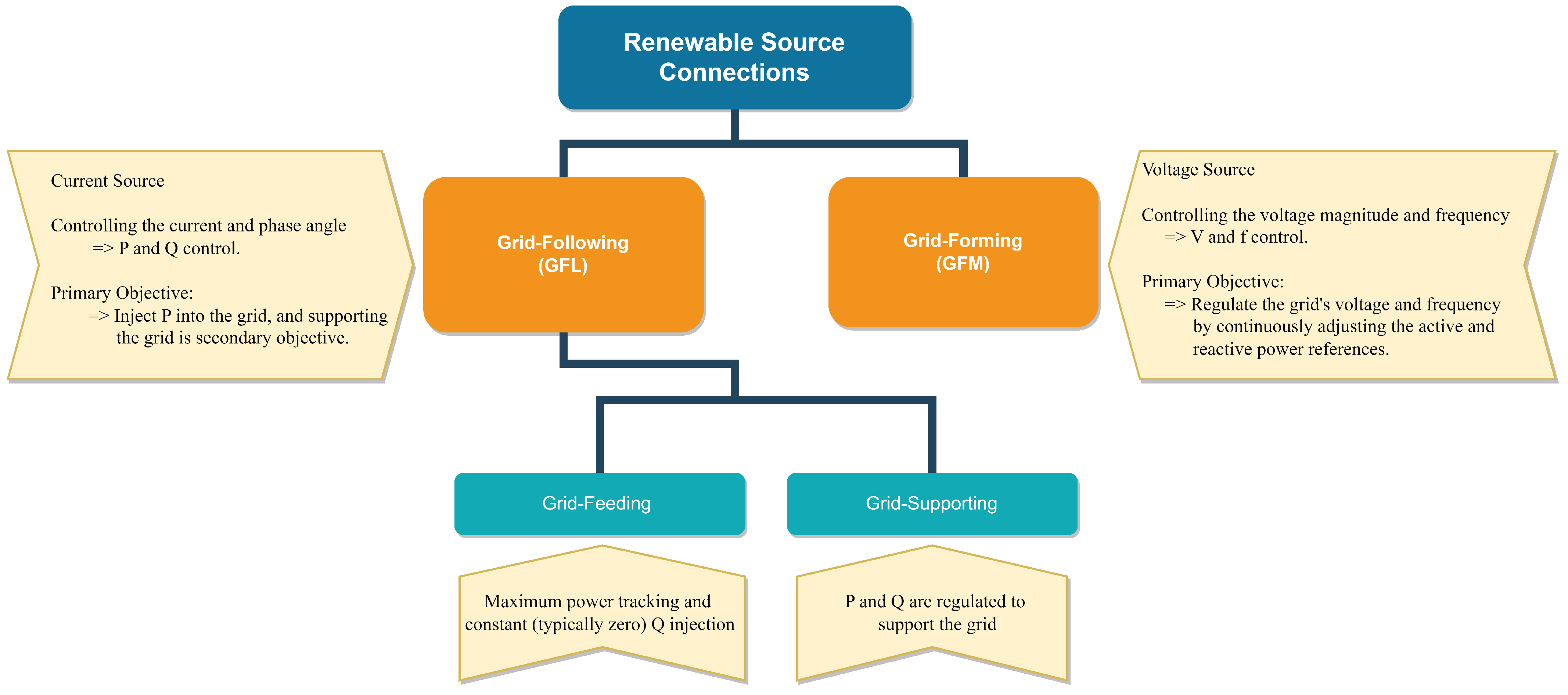
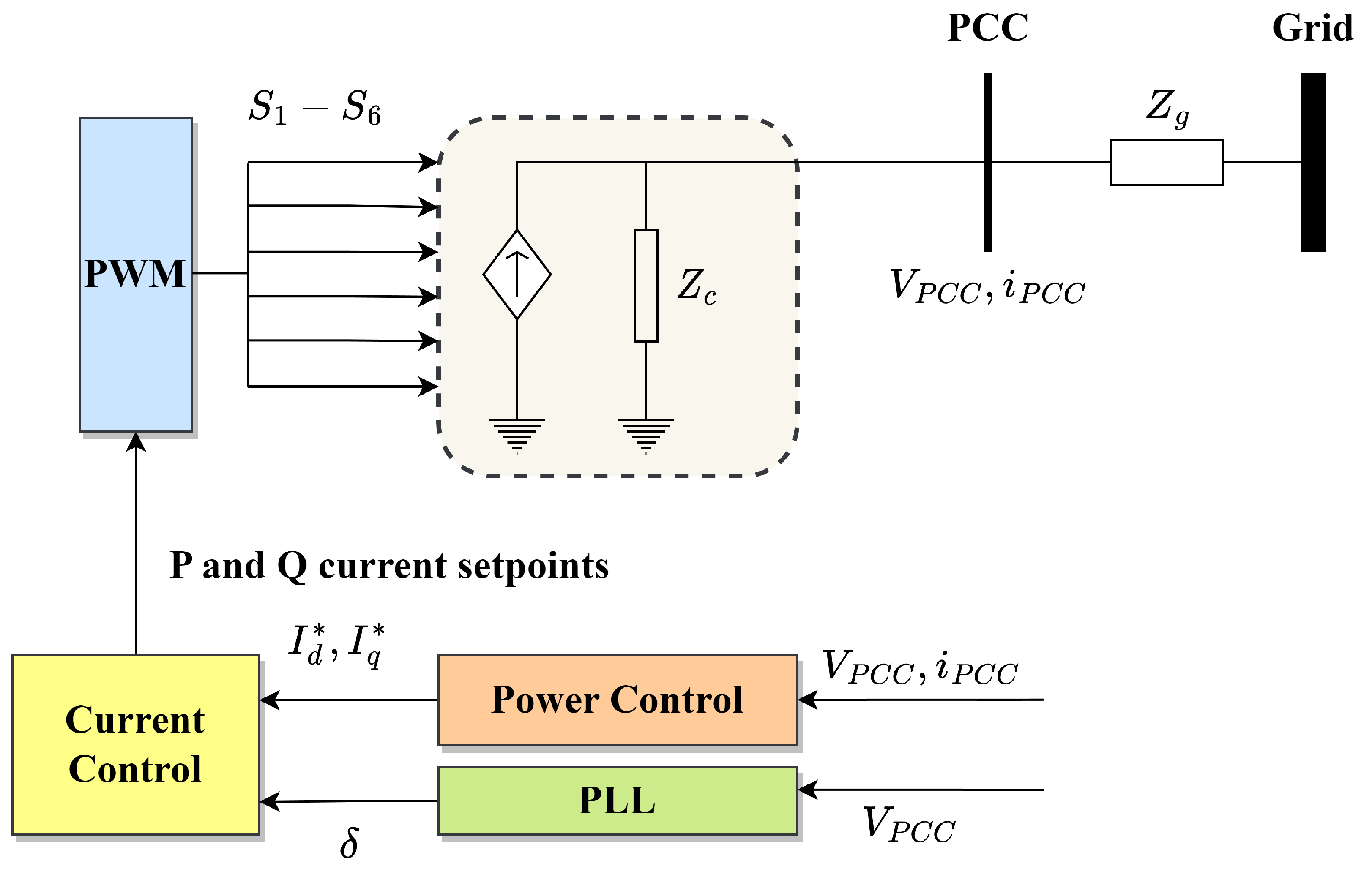
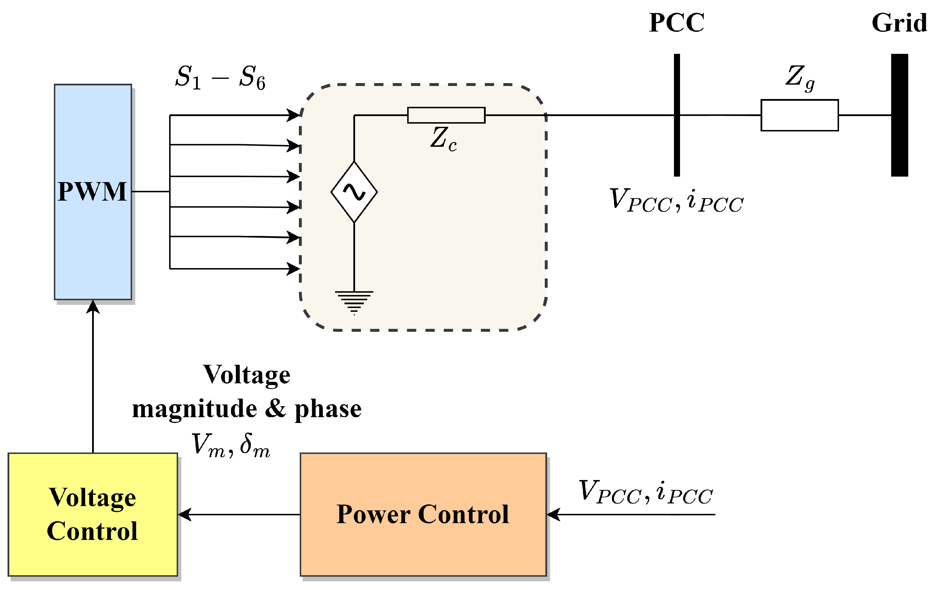
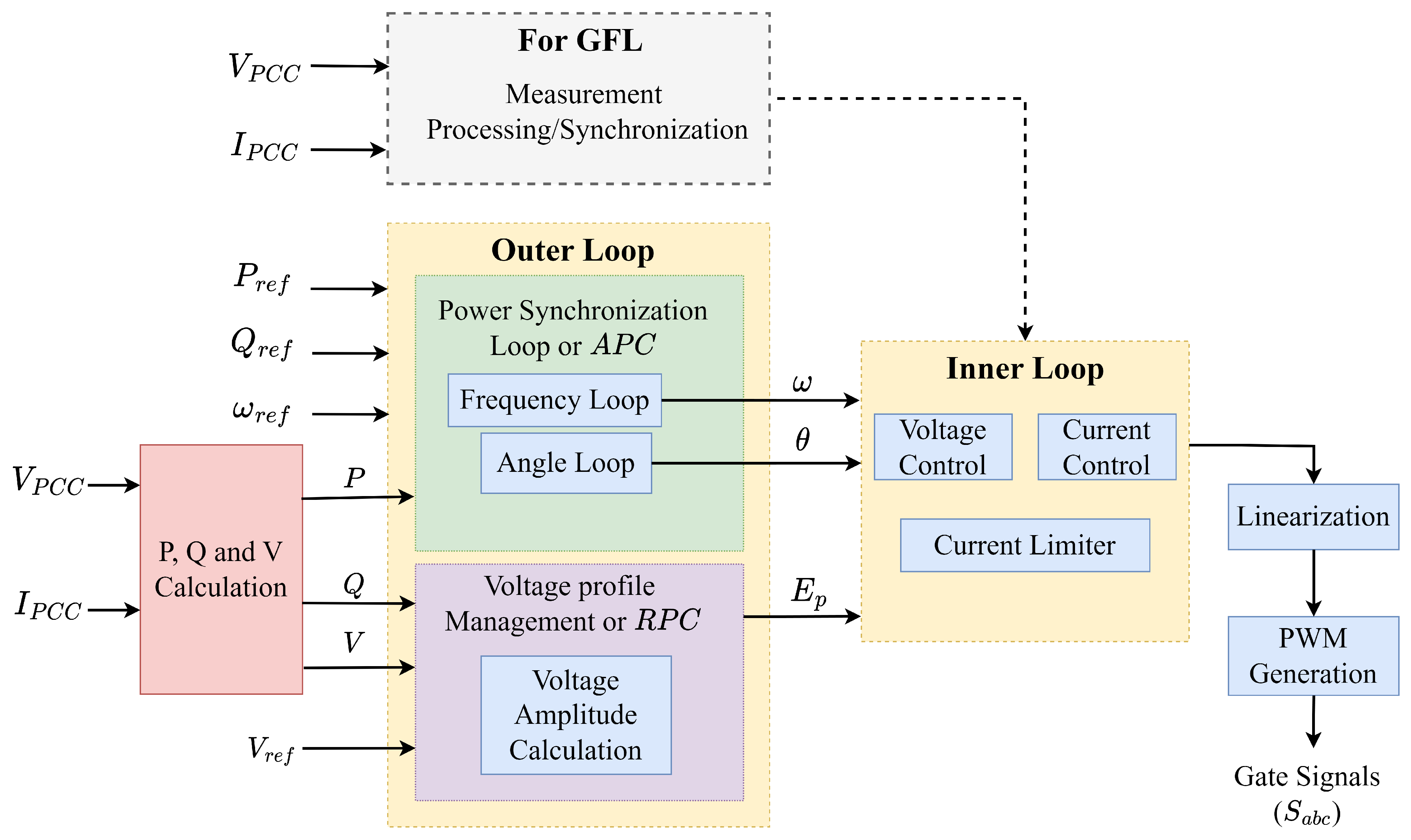
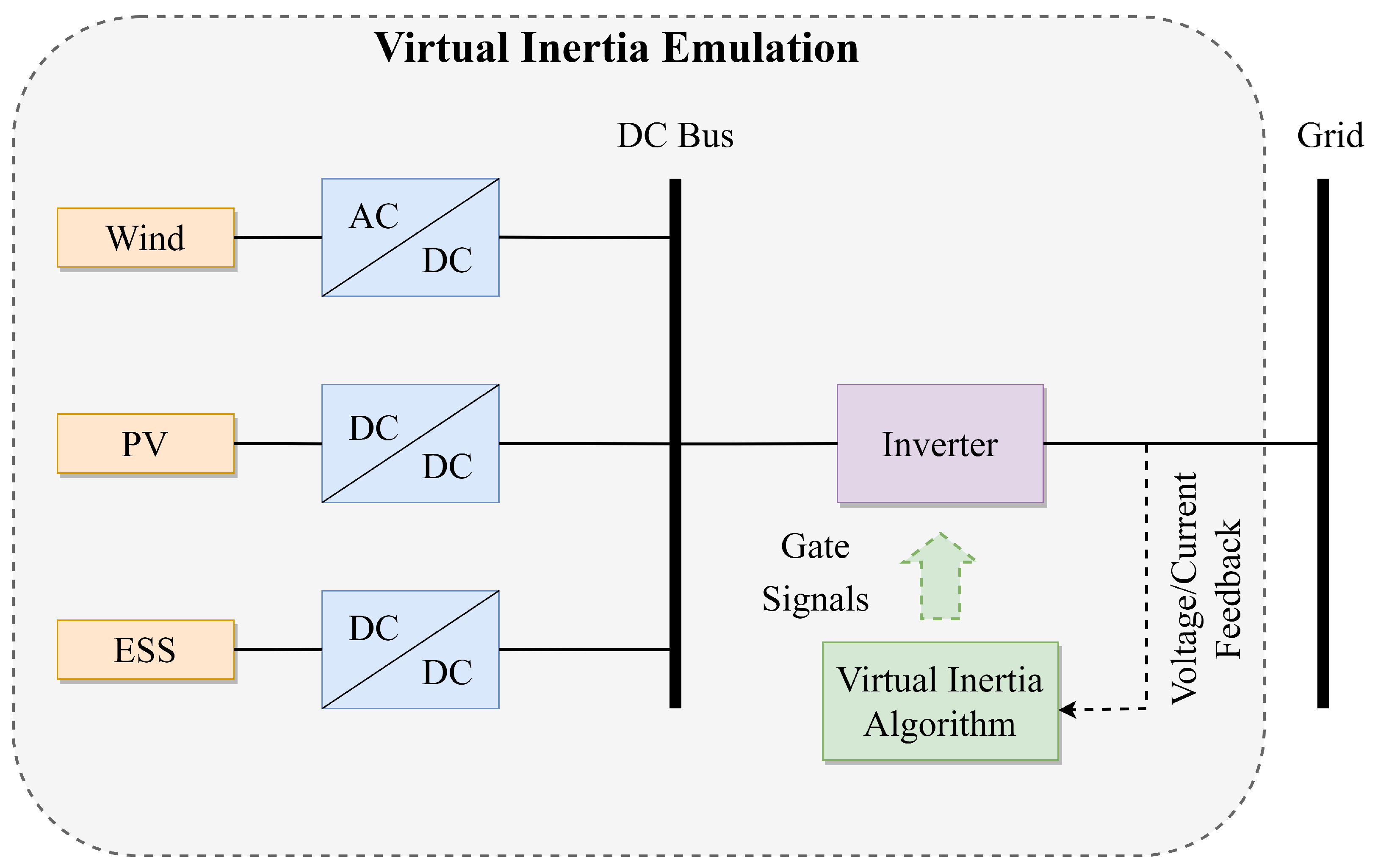
2. Classification of Renewable Source Connections to the Power Systems

Based on interactions with the grid, responses to variations in the grid, and the implementation of converter/inverter controllers, renewable source connections to the power grid can be classified as G F L and G F M . The following section provides explicit descriptions of the G F L and G F M topologies, and Figure 1 outlines the distinguishing characteristics.
Presently, the vast majority of V S I s are current sources, commonly known as G F L , because they follow the power grid’s voltage and frequency, as specified by synchronous machines connected to the power grid [51]. In G F L , active power injection into the grid with maximal power point tracking M P P T is the core focus. Nevertheless, the reactive power injection is minimal and frequently near to zero for the grid-feeding mode. In contrast, the grid-supporting mode delivers reactive power at a predetermined droop level in response to voltage fluctuations. Most large-scale grid-connected converters/inverters operate in grid-supporting mode [52].
As depicted in Figure 2, the control characteristics of a G F L converter can be modeled by a controllable current source with a high impedance in parallel Z c [29]. At the P C C , the converter measures both the voltage and current V P C C , I P C C and employs a P L L to compute the phase angle δ required for grid synchronization through the equivalent grid impedance Z g . Thus, a dedicated synchronizing unit is necessary for G F L to maintain synchronism with the power grid. The terminal voltage is adjusted to provide direct and quadrature axis line currents I d * , I q * , followed by the provision of active and reactive power supports. Consequently, the reliability of the current control approach is primarily dependent on rigid grid conditions. However, when power systems incorporate many high-capacity G F L converters, their influence will no longer be limited to the local region or area but will continue to affect the whole power network. Henceforth, the power system’s total dynamic performance is considerably impacted.
In G F M , an inverter’s control behavior can be modeled using a controllable voltage source with a low series impedance Z c , as illustrated in Figure 3. Unlike G F L , G F M does not measure V P C C for grid synchronization; instead, it forms V P C C to regulate the power output by continually varying the active and reactive power references [29,53]. Accordingly, the G F M can regulate the voltage and frequency for a reliable electric power system. It can even provide local loads without a grid association by setting its reference voltage and frequencies [1,52,54,55].

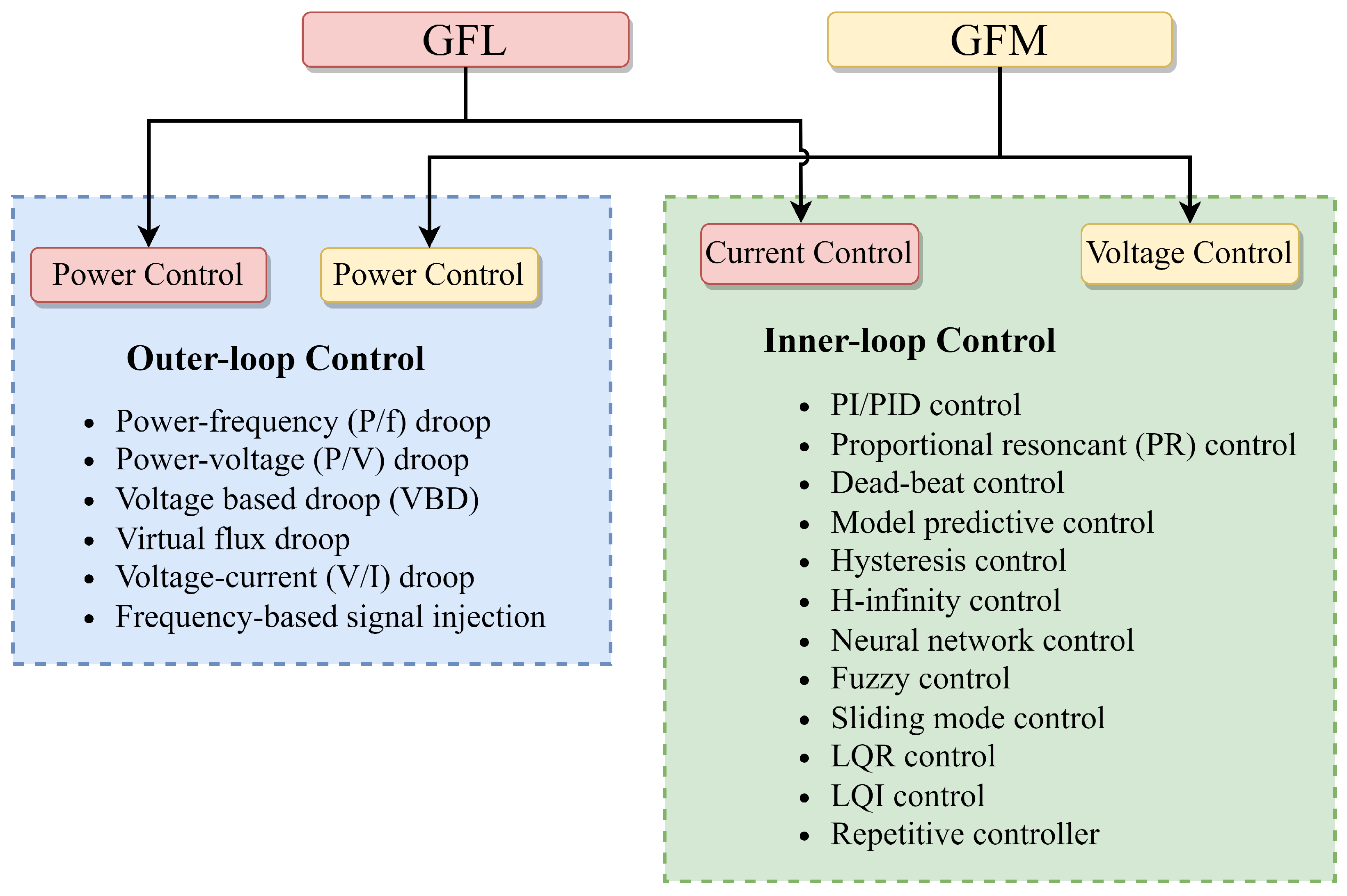
3. Voltage Source Converter/Inverter Topologies

Numerous converter/inverter topologies and configurations based on controller structure or characteristics are described in the literature [29,56,57,58]. Figure 4 illustrates the generalized control structure of V S C / V S I s, with the emphasized outer and inner control loops. The outer control loop calculates the frequency, angle, and amplitude of the internal virtual voltage source and achieves strategies pertaining to voltage and frequency stability, as well as power sharing in the loads’ connection. An inner control loop consists of all further control actions known as cascade control, which includes both voltage and current controls at the device level. The cascade control provides an appropriate modulation signal for P W M and is accountable for the immediate monitoring of the system’s nominal voltage and power quality concerns. In addition, this generalized control structure includes schematics of measurement processing and synchronization that is relevant solely to G F L -type converter/inverters. The outer loop determines the set points for the internal loops depending on system-level needs, such as virtual inertia emulation, reactive power and voltage regulation, scheduling, and dispatch of auxiliary services. Nonetheless, the device-level inner control loop is mostly employed to protect converters/inverters from excessive currents and generate the corresponding signals required for P W M .
There are several control techniques based on outer and inner control loops, and the study of each methodology continues to expand with the development of sophisticated control algorithms. However, this article’s major objective is to assess the literature on transient stability analysis and enhancement strategies for renewable-dominated power systems. Therefore, a list of categories of control strategies along with a brief description and references is provided for the reader’s basic comprehension.
Figure 5 categorizes the prevalent control strategies which are exploited for both outer and inner control loops. All of these controls are intended to enhance the system’s power quality, disturbance rejection, control complexity, and reliability. The control techniques are conceptualized from basic to complicated analytical approaches based on the grid’s features, and the comprehensive explanations of each control can be found in [59].
Traditional power grids with S G s have inherent substantial inertia and damping, which are worthwhile for the reliable functioning of power grids employing governors and automatic voltage regulators A V R . When disturbances cause power imbalance, the inertia property resists the frequency shift and aids in reducing the frequency nadir and the R o C o F . On the contrary, renewable sources of electrical energy that are interfaced via inverters do not possess the same inertia and damping as S G s. Thus, different research works propose control strategies based on outer-loop control that can imitate the S G ’s features on the inverters, namely virtual inertia [60]. As a result, several research works suggest control solutions based on outer-loop control that may mimic the S G properties on inverters, particularly the virtual inertia feature.
Figure 6 illustrates the fundamental concept of virtual inertia emulation with the inverter-connected grid. Virtual inertia is a collection of control algorithms, renewable sources, energy storage devices, and power electronics that imitate the inertia of a power grid and provide proper gating signals to represent these resources as S G s from the grid’s perspective, according to voltage and current feed from the inverter output [61]. Additionally, the inertia simulation of the G F L inverter manages frequency by injecting active power proportionate to the frequency variation and R o C o F in the grid. The inertia emulation of a G F M inverter is a voltage source that adjusts for the imbalance of generated and consumed power by altering the frequency of the generated power.
Although the fundamental notions underpinning inertia emulation topologies described in the literature are identical, the implementation varies greatly depending on the application and estimated complexity level of the model. Specific topologies adopt a theoretical formulation that exactly characterizes the S G s’ dynamics in an effort to emulate their exact behavior, while others utilize a strategy that makes the inverters sensitive to frequency transformations in the grid. Figure 7 depicts a general categorization of the several topologies available in the literature for implementing virtual inertia, and [62] provides detailed descriptions of all fundamental techniques.

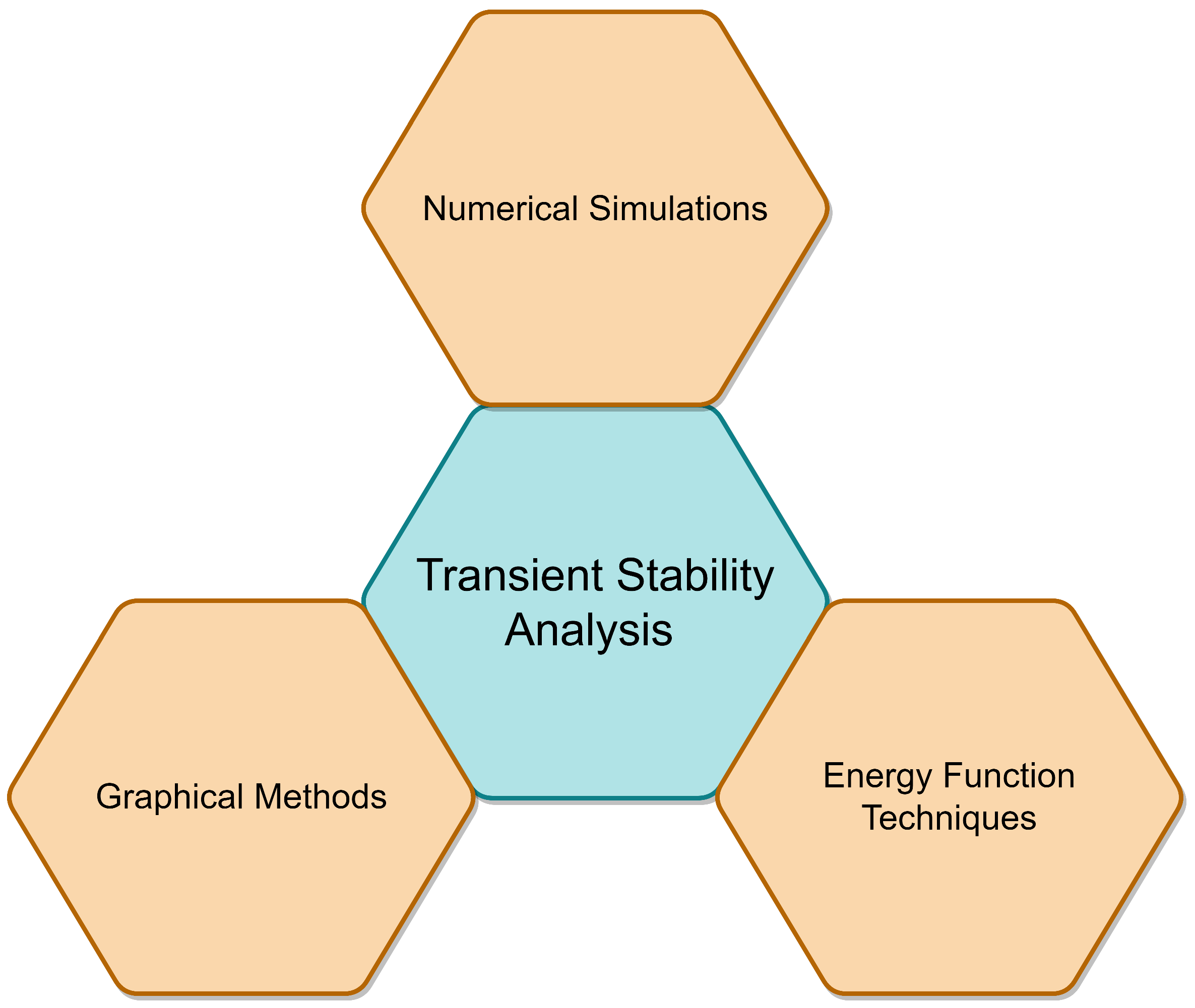
4. Transient Stability Analysis Methods

Transient stability analysis techniques of conventional power grids based on the time, energy, and frequency domains can be employed in the transient stability analysis of R E S -dominated power grids [45]. There are three extensively employed transient stability analysis techniques: numerical simulation methods based on the time domain, energy function techniques based on the energy domain, and an alternative graphical technique, as shown in Figure 8.

4.1. Time Domain-Based Numerical Simulation Techniques

Time domain-based numerical simulations are the most popular and reliable approach in power system stability analysis [63,64,65]. The simulation tools model the behavior of power systems over time and are employed to study the dynamic response of the system to various circumstances, such as faults and load changes. They are also commonly used to verify the accuracy of stability evaluations achieved by other techniques [66]. To create a discrete, iterative computation model suited for computer simulations, a mathematical model describing the system’s physical characteristics must be developed with the aid of an adequate programming language or simulation tool [67]. Simulations provide valuable insights into the behavior of power systems and are essential for the power system’s configuration and functioning, despite their time-intensive nature. The system’s stability remarks from the numerical computations are examined either from the quantitative outcomes or graphical results obtained from the simulations.
Numerous studies have examined the transient stability of R E S -penetrated systems via numerical time-domain simulations. In [68], the impacts of various control strategies on microgrid stability after fault-forced islanding were examined. Simulation findings indicated that the critical clearing time C C T strongly relies on the microgrid control approach. The loss of synchronism L O S of inverter-connected systems driven by inadequate current infusion is studied in [69] via numerical simulations. The voltage and frequency transient stabilities based on the definitions of German grid codes are considered for the investigations. However, ref. [70] calculated voltage angle deviations of the generations to determine the transient stability of a multi-virtual synchronous generator V S G in microgrids. As demonstrated in [71], V S C / V S I s, loads, and control loops may be independently modeled and subsequently combined, irrespective of the system’s topology and dynamic interaction sophistication.
The sub- and super-synchronous frequency oscillations cannot be simulated by the conventional transient stability models employing fundamental frequency phasor solutions [72]. In contrast, an electromagnetic transient E M T model has sufficient information to reproduce the electromagnetic phenomena-based dynamics over a range of timescales [73]. E M T tools have been designed and employed to handle mathematical challenges in transient investigations. However, these methodologies are usually built for balanced networks and are therefore inadequate for investigations involving unbalanced networks. Furthermore, E M T standards can depict the dynamics of converters and the associated controls; thus, it is a typically employed approach for analyzing converter/inverter-penetrated system stability [74,75,76,77].
When the power network is extensive, complicated in control, dispersed in timing, and comprises a large number of V S C / V S I s with different roles, it is difficult to correctly assess the exact characteristics of dynamic operations over an extended time. In addition, time-domain simulations do not deliver a closed-form answer to the transient instabilities and demand numerical or computer system models based on the intricacy. Consequently, simulations in the time domain can only reflect the resilience for a specific initial condition at a given period [78,79]. Thus, the understanding and instinct of operators who perform these simulations are crucial for arriving at an accurate solution or objective.

4.2. Energy Domain-Based Energy Function Techniques

Lyapunov’s second approach is utilized to investigate nonlinear systems’ stability without linearization. The Lyapunov function-based direct method is the energy function method in the energy domain [80,81,82]. The primary benefit of Lyapunov-based techniques is that a Lyapunov function permits the rapid assessment of the attraction region for a steady operational point and offers a cautious approximation of the disturbance that can be tolerated. Hence, the generator control and protection systems can be renovated accordingly to sustain system stability [83].
In the past few years, energy function techniques have been utilized in the modeling and analysis of R E S -dominated power systems. The power-angle curve-dependent equal-area criteria E A C were effectively implemented on the R E S -penetrated power system in [45,84,85] by transferring the principles, tools, and procedures of conventional power systems. In [86], the generalized potential and kinetic energies of wind turbines were assessed to produce analytical models in terms of rotor speed control time frames by incorporating controller effects synthetically. The system’s transient stability limits were then found by figuring out the relationship between the system’s transient and critical energy functions. Nevertheless, the absence of physical significance in the generalized energy makes it challenging to comprehend the theory of energy transformation in R E S with controls during severe disruptions. In [80], the strategy for resolving the C C T of the V S G -controlled V S C / V S I -connected infinite grid was presented. The energy function is produced by specifying the virtual rotor kinetic, potential, and stored magnetic energies with dissipated line impedance energy. In [87], the basic technique for creating the Lyapunov function was outlined, and the Lyapunov approach was used to develop a nonlinear representation of an islanded microgrid that quantifies the attraction domain of parallel V S C / V S I s.
The most significant benefit of energy function approaches is their ability to analyze nonlinear systems’ stability. However, R E S -dominated power systems with their nonlinear high-order models, flexibility in control switching, multi- V S C / V S I interconnections, and broad timescale range pose modeling and analysis issues [88]. This is detrimental to identifying the system’s steady-state functional point and limits the corresponding stability evaluation. In addition, it is challenging to develop an energy function that meets LaSalle’s classic invariance assumption [89] for many engineering and physical applications. These concerns pose a considerable barrier to energy function techniques for studying the stability of R E S -dominated systems employing more realistic models. Consequently, energy function approaches are primarily utilized in single-machine infinite bus S M I B system analysis, and V S C / V S I s are frequently reduced to a low-order nonlinear differential-algebraic equation D A E representation overwhelmed by P L L [90]. In [87,91], the droop and V S G -controlled V S C / V S I were reduced to inferior-order D A E representations governed by the droop or swing equations. The E A C depending on the energy function approach in [45] is an efficient way to empirically interpret the quick reactions and theoretically study the transient strength of V S C / V S I . Accordingly, future research on R E S -dominated systems should emphasize design-oriented energy function techniques that are essential for detection algorithms [92], controller design [93], threshold determination [91], and stability enhancement [90].

4.3. Graphical Techniques

Graphical techniques include power, frequency, voltage angles with E A C , and phase portraits, which are predominantly exploited in S M I B systems [94]. In [45], the basic ideas, techniques, and strategies of transient stability of conventional power systems were initially transitioned to study the dynamic responses and instabilities of the R E S penetrating the system, and the presented approach has been extensively utilized in the literatures [46,92,93]. Physical interpretation of graphical techniques is straightforward, allowing for a clear description of the instability process. Nonetheless, they are exclusively appropriate for investigating low-order (primarily S M I B ) systems. In contrast, phase portraits can only be employed to analyze the behavior of two-dimensional autonomous systems stability [47].
E A C is a straightforward strategy for evaluating the transient stability of an S M I B system or a two-machine-connected system without solving nonlinear swing equations and assumes energy conservation depending on the kinetic and potential energy when assessing the transient stability. This approach is valid only if the non-conservative damping force equals zero. Because no system shows zero damping, this technique may conservatively produce an incorrect stability estimate. Phase portraits were investigated to evaluate the system’s stability, including damping. Therefore, nonlinear differential equations of the first and second order that cannot be resolved explicitly via analytic approaches can be computed visually using phase pictures [95].
In [80,87], the power-angle curve was utilized to determine the transient stability of single and double V S C / V S I systems. The authors of [45] analyzed the large-disturbance D C voltage instability of the inverter-connected S M I B system using power-angle curves with E A C . In addition, refs. [91,96] discovered that transient instability can originate during substantial disturbances that saturate the inverter currents. The instability process is physically described by employing the power-angle curves of V S C / V S I -based S M I B systems. However, refs. [90,93,97] emphasized V S C / V S I depended on S M I B systems and evaluated whether the balance points are available during significant disruptions. The voltage-angle curves establish the power synchronization, droop, and V S G controls. Moreover, the frequency-angle curve presented in [98] demonstrates the impact of grid resilience on the dynamic features of D C voltage management in a double-fed induction generator. It investigates the mechanisms of voltage–frequency coupled transient instability [99].

5. Transient Stability Enhancement Techniques

The S G s possess rotational inertia owing to their rotating parts. They can inject kinetic potential energy stored in their spinning portions into the grid during unexpected disruptions. Therefore, traditional power systems with a substantial percentage of S G s are resistant to instability. On the other hand, the penetration of R E S poses several problems to the system’s stability. The most challenging aspect is the synchronization of the inverter-based device with the grid and keeping it in pace with the grid regardless of disturbances or changes [100]. Consequently, the system is susceptible to loss of synchronism L O S owing to insufficiently balanced energy injection to the grid at the appropriate time intervals.
To enhance the transient stability of conventional power grids based on S G , fast-acting protective relays and circuit breakers are employed to rectify faults within a reasonable time frame [101]. However, this strategy cannot tolerate the transient fluctuation caused by disruptions external to grid faults. The potential hazards posed by relays and circuit breakers may threaten transient stability. Therefore, instead of depending exclusively on protective mechanisms, it is worthwhile to investigate inverters’ control techniques or strategies during significant disturbances.
The dynamics of P E -based inverters largely depend on their digital control algorithms based on multi-time scale, programmable, and highly nonlinear characteristics [21]. Thus, extensive research has been devoted to the grid-connected inverters’ control algorithm mechanisms to enhance reliability and stability [102]. Recently, many control strategies have driven the development of numerous stability-strengthening solutions for both G F L and G F M   R E S grid connections. The following sections provide extensive descriptions and comparisons.

5.1. Grid-Following Systems

For strengthening the transient stability of G F L inverters, there are two different kinds of control techniques. The first control technique modifies the injected active current or power during a malfunction, while the second involves synchronization unit alterations. The research articles in each category, along with their publication years, are outlined in Table 1, with explanations presented underneath.

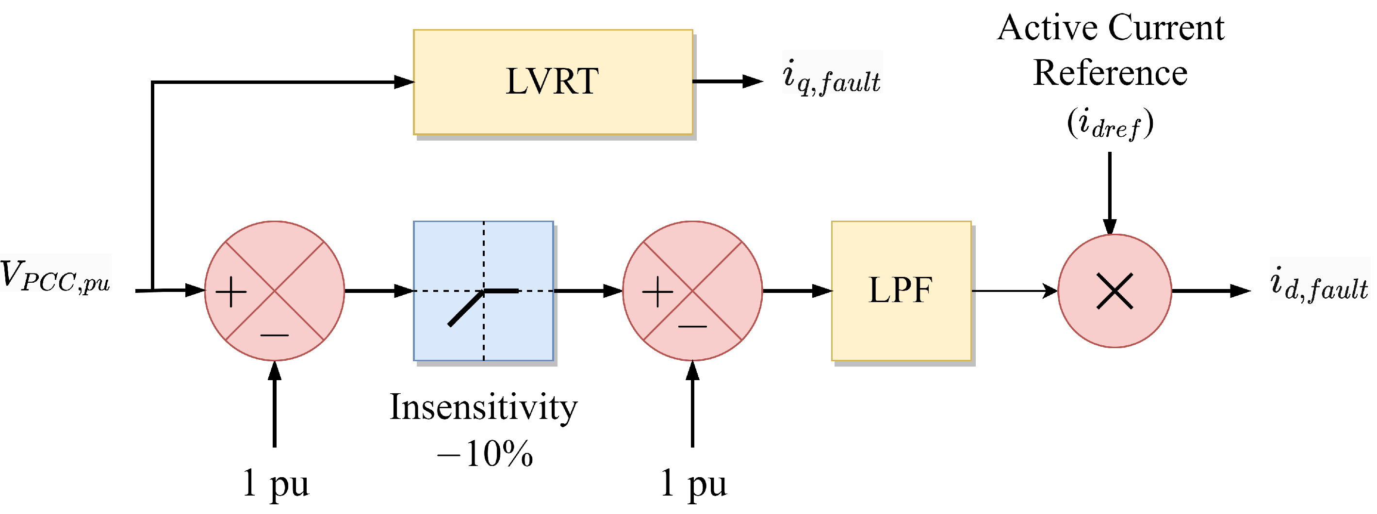
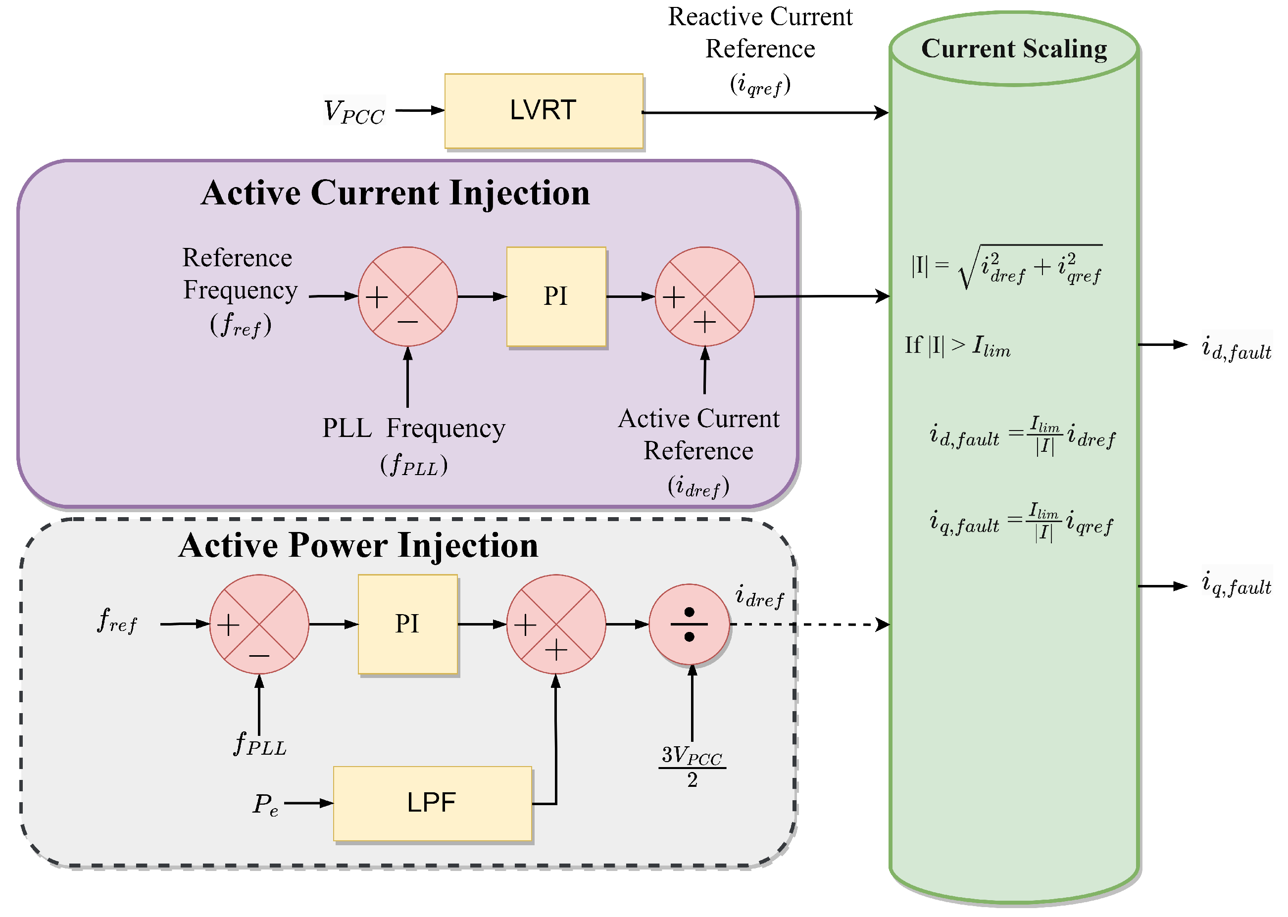
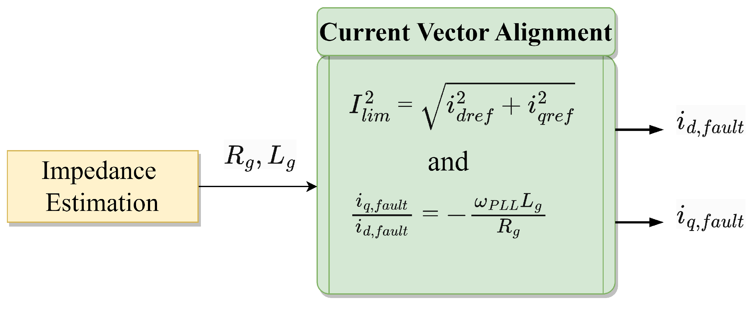
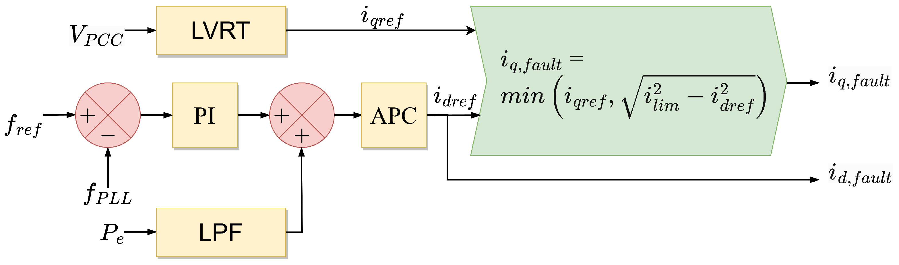
5.1.1. Modify Active Current or Power

In [103,104], a control strategy was presented that, to increase the transient resilience margin, the real portion of the output current is lowered relying on the voltage drop experienced by the network. Figure 9 shows the control configuration for a voltage-dependent active current deduction. During faults, the reactive current is restricted to 1 pu, and the inverter is capable of short-term overload; hence, active current injection is possible. Simulations revealed that the control strategy minimizes the risk of synchronization loss in the circumstance of grid disturbances. This control implementation is straightforward; however, a reactive current cannot be injected independently during a fault due to the low active current.
The study in [105] presented an active current injection strategy based on P L L frequency error to raise the active current illustrated by the solid block in Figure 10. The proposed technique incorporates a closed-loop control that employs the P L L frequency as feedback to catch L O S and handle the active current to ensure that the injected current vector advances to a steady region. This technique has the benefit of being able to treat concerns with either an excessively low or high fault current. However, it adds closed-loop control, whose resilience is not explained nor verified. Therefore, the study in [106] offered a similar strategy that modifies the active power reference as opposed to the active current depicted in Figure 10 with a dashed block.
According to [90], a stable working region can be established if the injected current vector is matched with the negative grid impedance angle. This approach provides reliably stable performance, and its transient stability can be demonstrated analytically; nonetheless, a quick determination of the impedance angle is necessary during fault. Therefore, Ref. [107] introduced a control scheme, which estimates the impedance angle and is utilized for stability enhancement illustrated in Figure 11.
Furthermore, Ref. [108] proposed an approach comparable to those mentioned in [17,113], where the stabilizing concept is built on the E A C ’s core principle. If the measured active power is employed as a reference, P m e c h = P e l e c implies that the accelerating and decelerating areas are extracted, and the resilience can be attained with any positive damping components. Because damping is a nonlinear function of δ , its positivity cannot be guaranteed, and ref. [108] employed a proportional-integral controller on the P L L frequency error to overcome this issue, as illustrated in Figure 12. The corresponding gain of the controllers offers supplemental damping, which can compensate for the occurrence of negative damping.

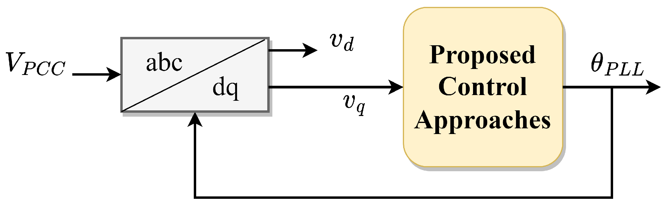
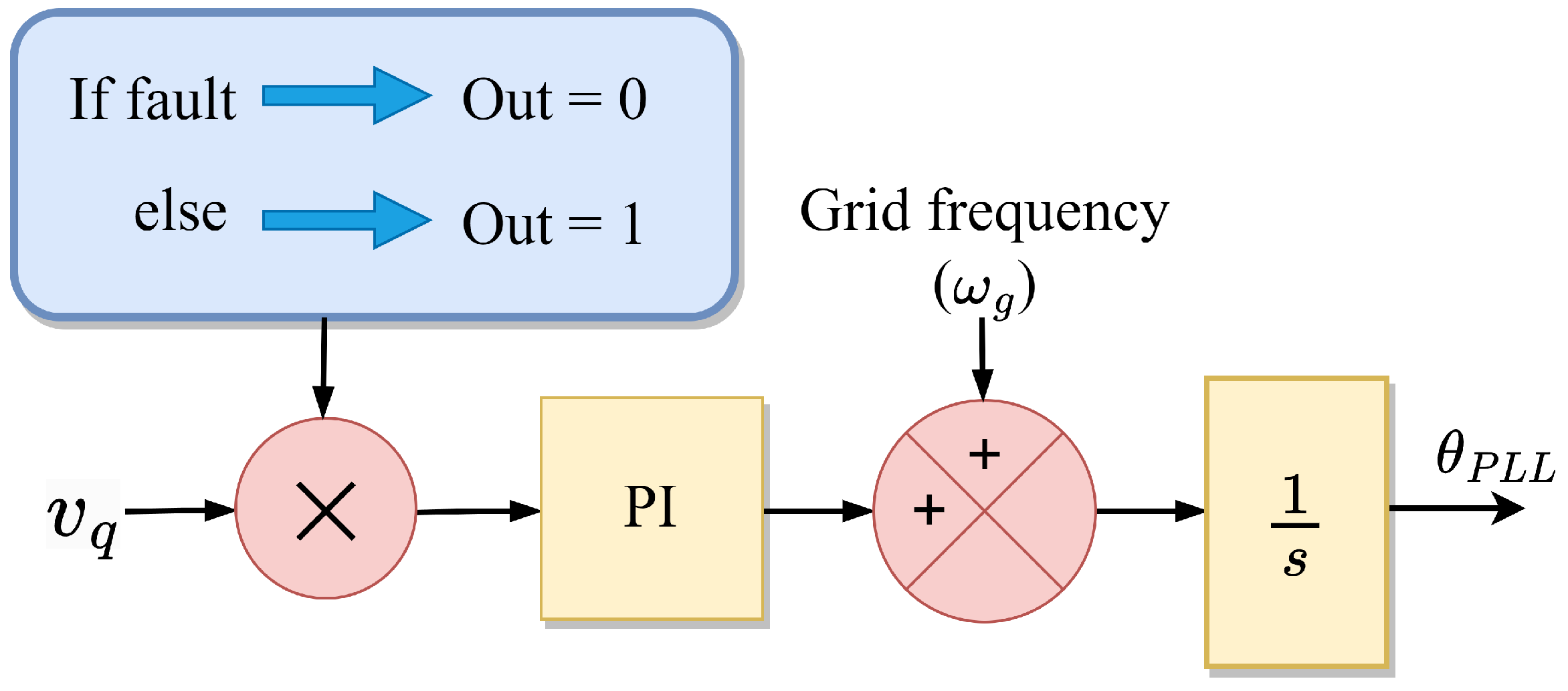
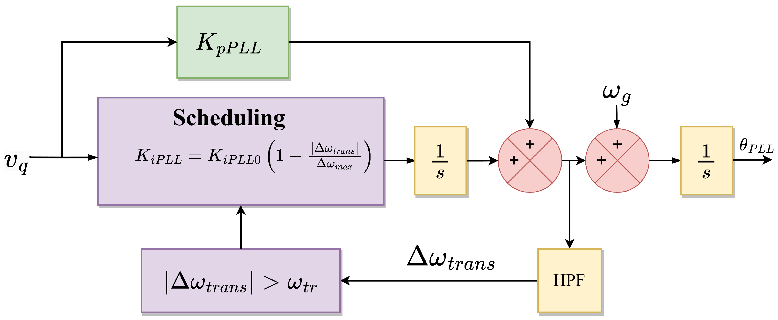
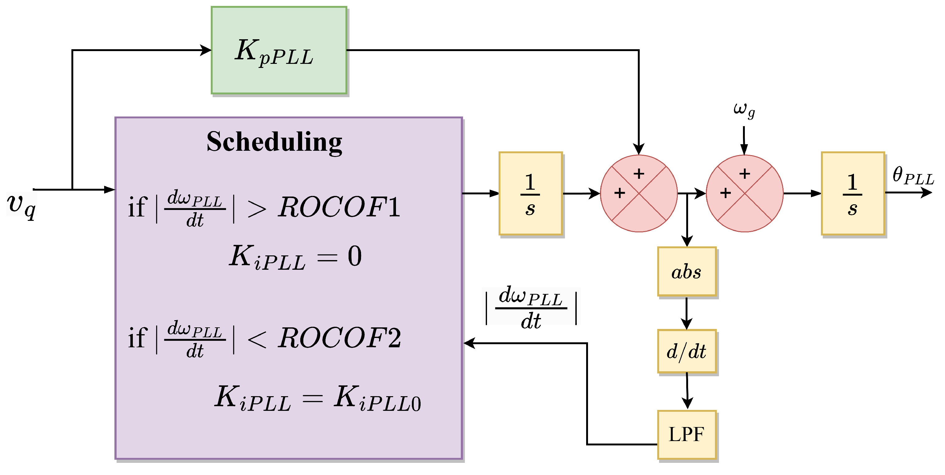
5.1.2. Modify Synchronization Loop

The second branch of stabilizing control approaches for G F L inverters involves modifying P L L control settings to improve transient stability. Figure 13 depicts the overall control diagram of P L L , which incorporates the newly suggested control approaches on the v q -parameterized loop. There are four approaches presented in distinguishable works based on the adjustments on the v q control loop, and the details are provided below.
The first approach is from the studies of [69,109] who discussed the P L L freezing technique. This approach eliminates the P L L control error upon sensing a defined catastrophic fault, as illustrated in Figure 14. It enables the P L L -synchronized inverter to function in a configuration independent of P L L depending on frequency and phase assessments produced prior to the fault. This approach allows the converter to function for all situations, notably zero-voltage conditions while keeping a constant operating point regardless of the fault’s severity. Moreover, faults produce phase-angle spikes and frequency fluctuations due to their fixed internal states.
In the second approach described in [110,111], the proportional and integral gains of the P L L are adjusted to boost the damping, thereby enhancing the system’s transient stability depicted in Figure 15. This approach is straightforward to develop; however, it only functions if the inverter has two equilibrium points during the disturbance, and there are no suggestions for parameter tweaking.
The third approach in [112] provides gain schedules depending on the transient dynamics of the anticipated P L L -frequency, and if instability occurs, the integral gain is reduced to zero as shown in Figure 16. Unlike the approach described in [110,111], this method increases P L L damping during transients without requiring the selection of a predefined specific value. However, it cannot fix problems if only one equilibrium point exists or if the two operational points are incredibly far away from adequate resilience. In either scenario, the overshoot caused by second-order dynamics can result in destabilization, and for any circumstance, it can lead to instability.
The fourth approach presented in [92,110] involves transforming the P L L to a first-order loop during a fault, thereby avoiding the integral gain illustrated in Figure 17. The threshold determines the activation of the first-order loop as opposed to a voltage-based fault signal. Therefore, the proposed approach does not eliminate the integral advantage if there is no instability. The proper preference of R o C o F is described in [110], and the approach is able to stabilize any system with a minimum of one operating point. During an extreme fault, when there are no operational points, it is yet required to shift to a stable strategy, such as a P L L freezing approach or one of the previously listed approaches.

5.2. Grid-Forming Systems

Comparable to the transient resilience enhancement techniques of G F L presented in Section 5.1, the transient stability of G F M   R E S -connected systems can be enhanced. There are five classifications of control techniques for improving the G F M grid connection’s transient stability, as summarized in Table 2, and detailed explanations are provided below.

5.2.1. Modify Active and Reactive Power Reference

Even though G F M inverters with second-order power managing loops show comparable dynamics to S G s, standard practices, such as regulating the governor to lower the accelerating power and injecting extra reactive power to raise the outcome voltage during grid disruptions, can be readily applied to R E S -connected power systems. During voltage drops, the transient steadiness of G F M inverters can be improved by lowering the active power reference and/or raising the reactive power reference through P f and Q V droop controls of the V S C / V S I s [129]. The challenging part of such systems is quantifying power reference fluctuations, which requires prior knowledge of grid impedance.
In [80], a power compensation loop for the enhanced control of the converter was presented, as illustrated by the solid block in Figure 18. Constantly, the grid voltage is monitored to ascertain whether or not a fault situation existed in the system. In the event that the voltage falls below a predetermined threshold, additional torque is generated to minimize the reference torque and acceleration area, thereby enhancing the system’s transient stability. When the fault has been corrected, and the voltage level has been restored to the rated value, the additional torque is minimized to ensure that the inverter provides the rated power in a prudent manner, as indicated by the P-f droop curve. Consequently, the increased control does not influence the post-disturbance system, and the direct approach of Lyapunov could still be utilized to resolve the stability.
The study in [87] employed a similar control approach to enhance the transient stability of parallel S G - V S G systems, and the control configuration is depicted in Figure 18 with a dashed block. In a paralleled S G - V S G converter system, the time-delay connection causes an increase in input power during a fault, resulting in more considerable acceleration and more diminutive deceleration zones. Consequently, there is a substantial reduction in the system’s stability margin. The distinction in the angular frequency of S G and V S G is supplied to proportional control, which generates extra torque to modify the input torque, in order to improve the system’s stability. During steady-state situations, the angular frequencies of S G and V S G remain the same, and additional torque has no effect on the input torque.
The active and reactive power managing loops are interconnected; however, the contribution of reactive power control (Q-V droop) is commonly discarded. The reactive power loop regulates the voltage amplitude of the inverter, re-scales the active power provided to the grid, and significantly impacts the system’s transient stability. According to [114], reactive power regulation causes a significant voltage drop at the inverter terminal, which leads to a positive feedback loop that decreases transient stability. Consequently, the voltage drop is corrected by augmenting the reactive power reference via an additional control loop illustrated in Figure 19.

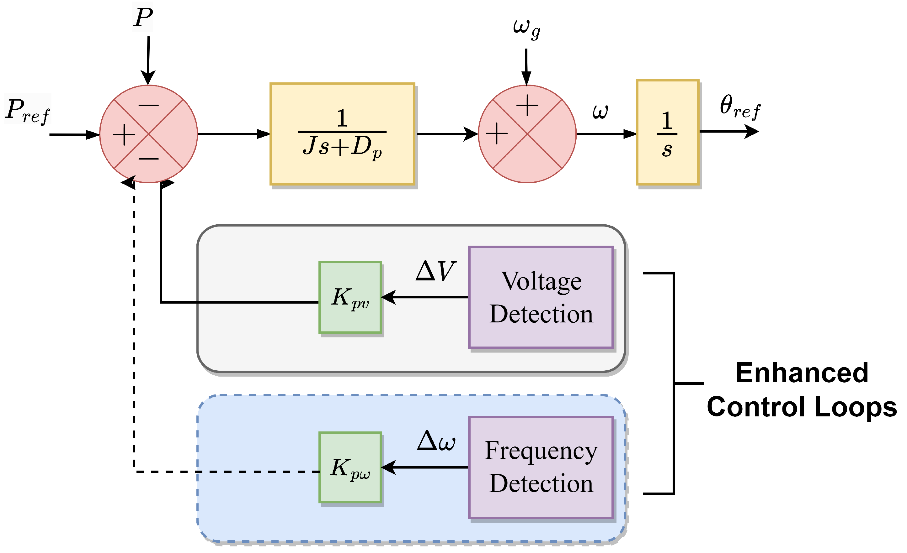
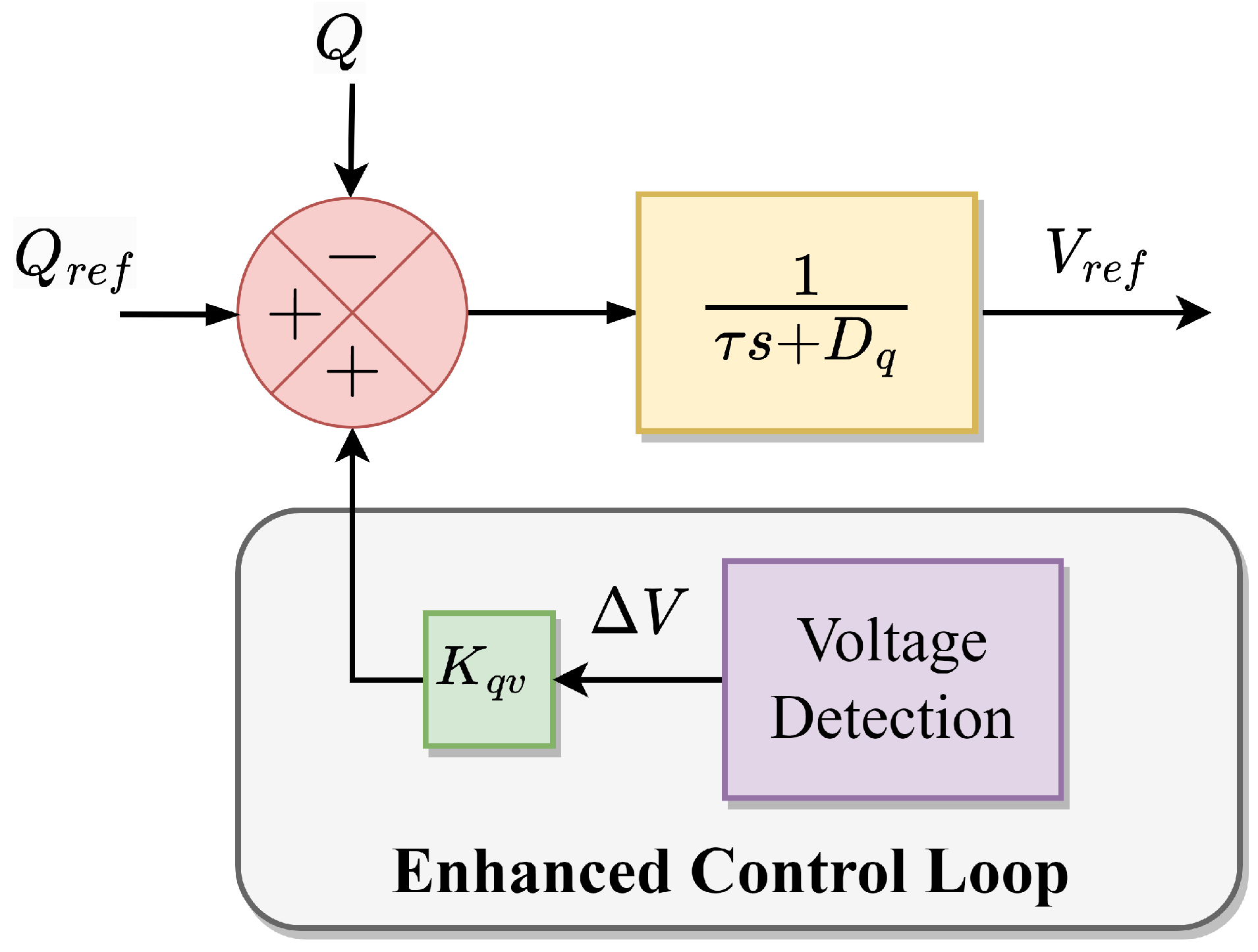
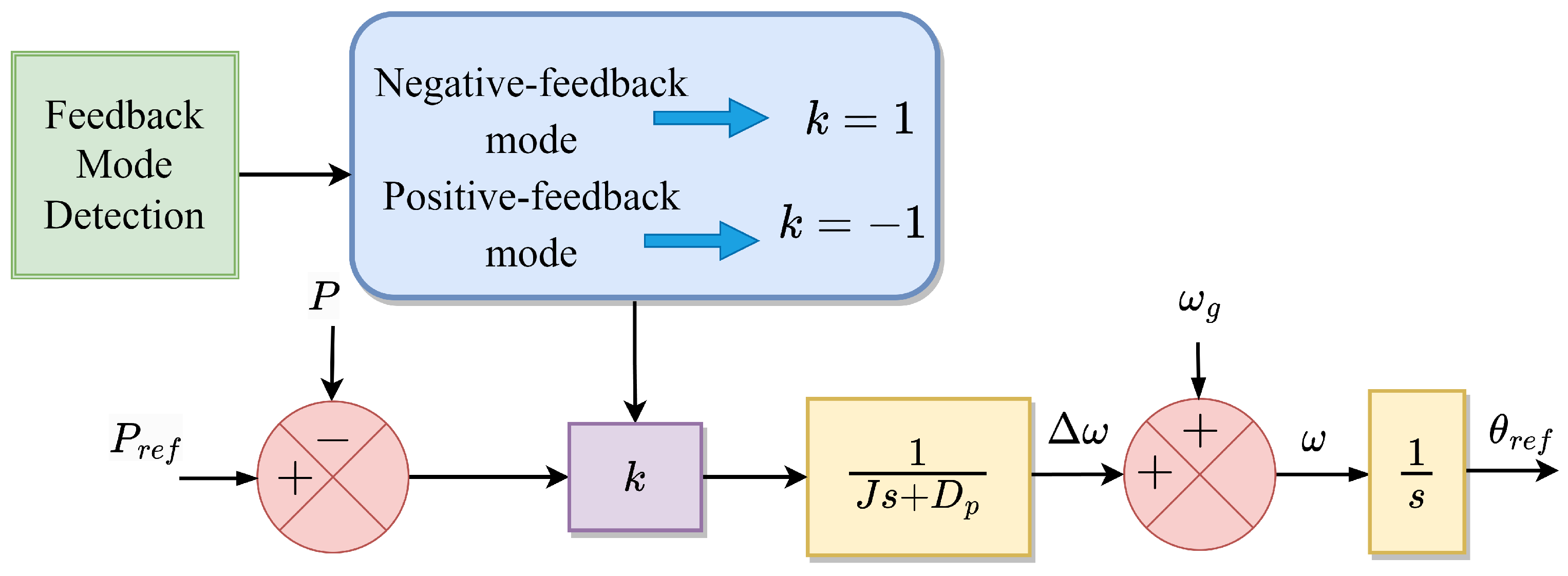
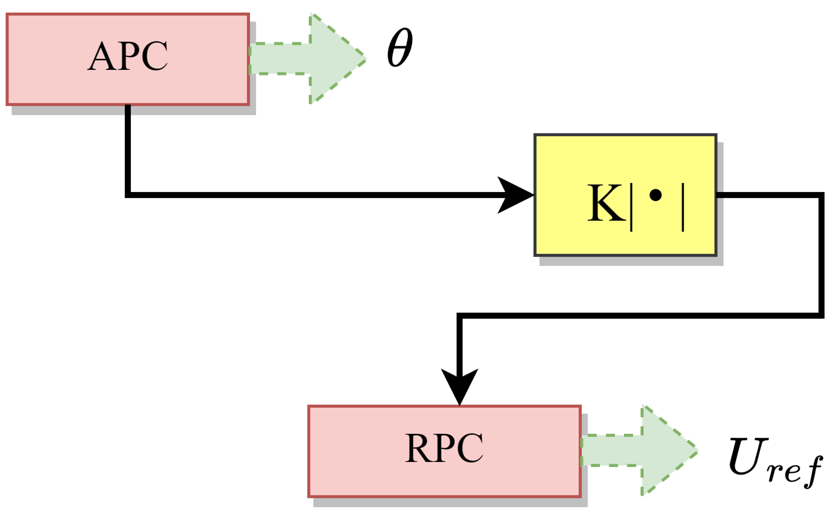
5.2.2. Modify Control Loops

In [115], a mode-adaptive power-angle managing technique for increasing transient resilience was described, which detects the feedback mode of the power-angle loop after a significant disruption characterized in Figure 20. The loop gain is then adaptively altered from positive feedback to negative feedback manner. Therefore, the positive feedback function of the power angle can be abolished, and the chance of L O S can be reduced when the system reaches equilibrium following the disturbance. In addition, mode-adaptive control can achieve a restricted dynamic behavior of the power angle in the lack of equilibrium points during extreme grid disruptions. Moreover, the inverter can be stabilized even when the fault-clearing time exceeds the C C T values. Therefore, it is not necessary to link the power control from the second order to the first order, and it is feasible to perform a wide range of modifications to the virtual inertia. Notwithstanding these facts, reliable detection of operational circumstances is required.
In [116], the transient angle stability of V S G -based grid-connected systems was investigated. This study investigated the resilience of the torque and power form emulation of V S G techniques, with the torque form being more stable than the power form under low inertia from the results. Subsequently, the influence of the inner voltage on the transient angle stability was investigated. A control approach was then provided that enhances the transient stability by minimizing acceleration zones and boosting deceleration zones with the appropriate internal voltage regulation as shown in Figure 21. U r e f and θ represent the internal voltage and angle of the V S G ’s active and reactive power loops, whereas K represents the control gain.

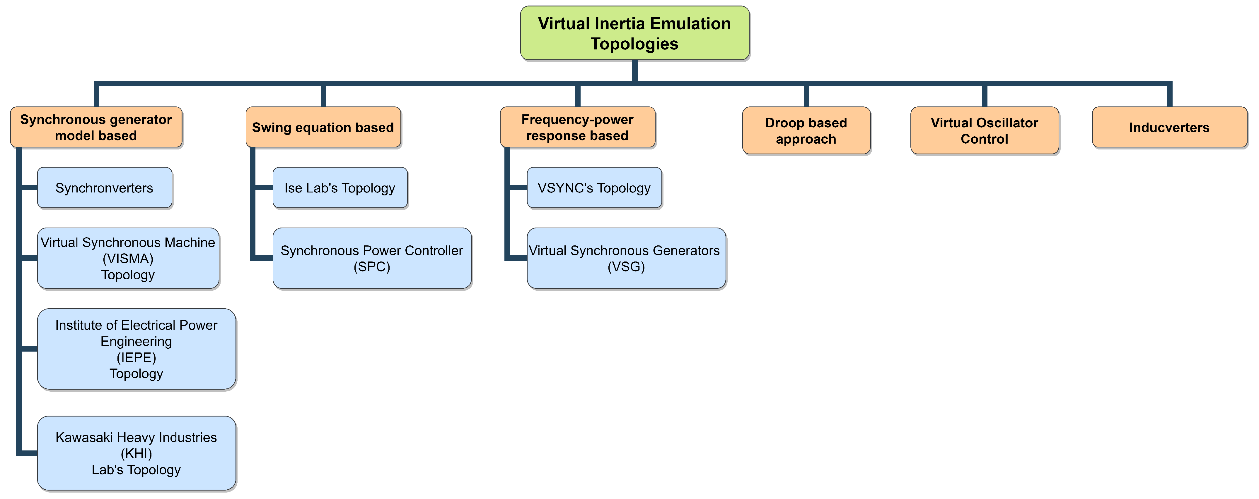
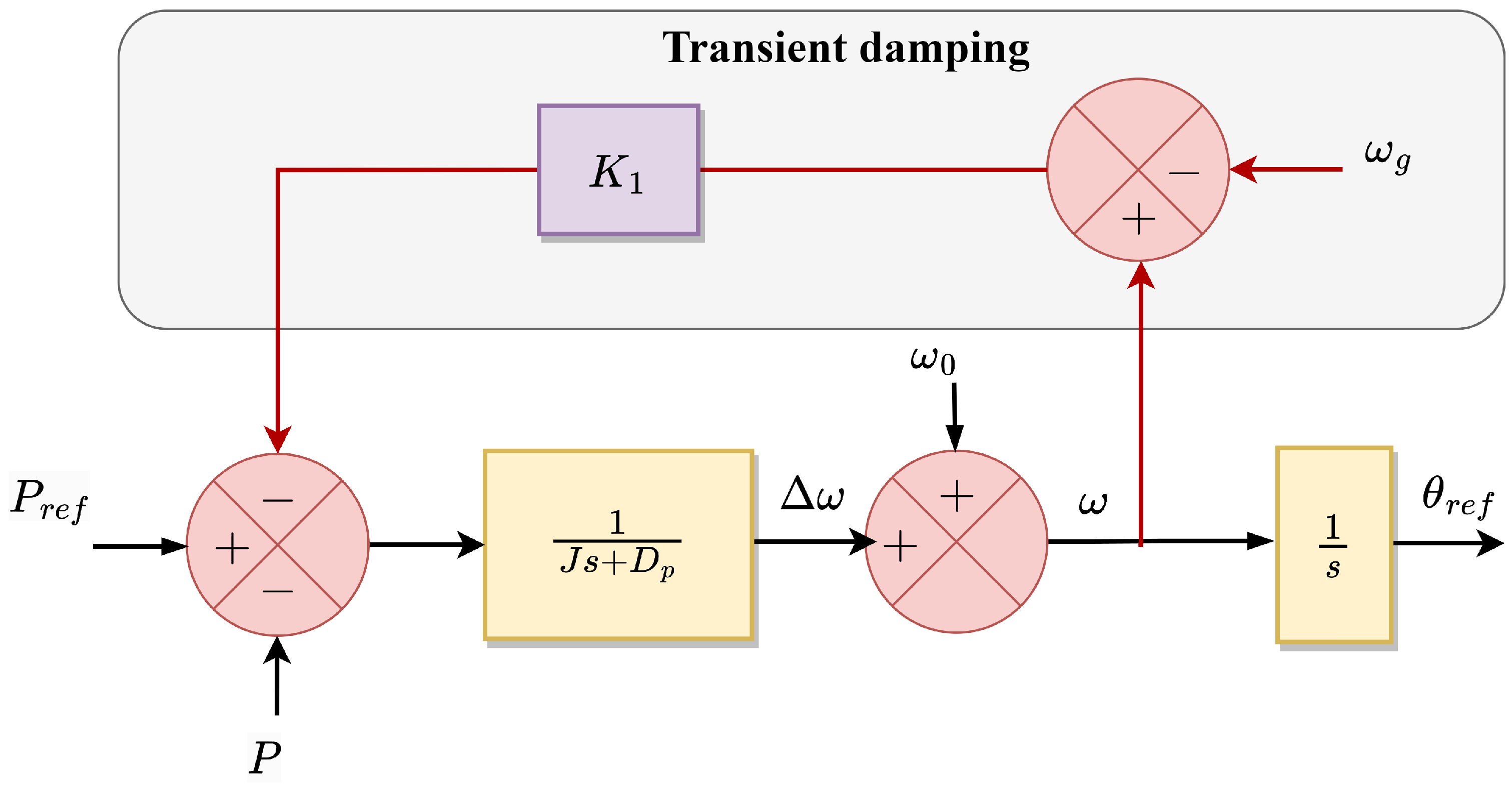
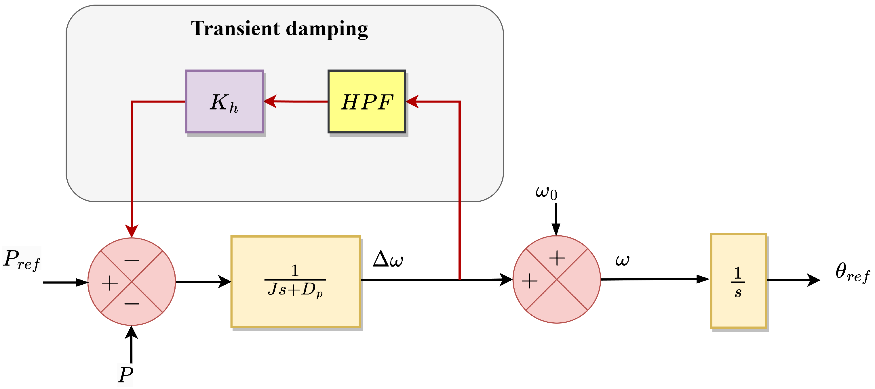
5.2.3. Modify Moment of Inertia and Damping Parameters

To improve the transient stability margin during large disturbances, fully controllable G F M inverters encourage ways of adjusting inverters’ moment of inertia. The paper [117] presented an alternating inertia scheme that assumes the right V S G ’s moment of inertia by taking virtual angular velocity and acceleration/deceleration into account per phase of the oscillation. The transient energy is scattered by damping terms during oscillations in S G s, but the alternating inertia control in V S G minimizes transient energy directly and prohibits its flow from DC accumulation and dissipation. With alternating inertia control, the transient energy can be minimized to zero at the completion of the first quarter cycle, and the resultant transients can be eradicated prior to their appearance in the system. Consequently, the damping imposed by alternating inertia is much more efficient and has similar results in all circumstances compared to the conventional damping factor, and the concept of adaptive inertia not only stabilizes the V S G unit but also improves the system’s stability for other machines.
A similar concept can be seen in [118], where two distinct quantities of virtual inertia were alternately utilized to augment the frequency regulation’s dynamics. To achieve the essential inertia, energy storage units must be integrated into V S G s, which increases system sophistication and decreases system performance. Without energy storage, the DC-link capacitance of V S G s would limit their virtual inertia, as per [45]. In [130], the explicit association of virtual inertia and DC-link capacitance, as well as design factors, was provided to introduce the notion of distributed power system inertia. The system inertia can be replicated by the energy stored in the DC-link capacitors of grid-connected power inverters without adjustments to system hardware. The DC-link capacitors are aggregated into an enormous equivalent capacitor that performs as an energy buffer for frequency aid, restraining the DC-link voltages correspondingly to the grid frequency. A comprehensive review of inertia enhancement techniques such as wind turbines, DC-link capacitors, ultra-capacitors, batteries, and V S M s depending on the advancements of frequency nadir and R o C o F in P E -penetrated systems was accomplished on [131].
Although virtual inertia enhances the frequency stability of a system, Ref. [93] showed that virtual inertia emulation reduces its transient stability by increasing the system’s order. Non-inertial V S C s, such as power synchronization control P S C and essential droop control, are first-order systems that can offer stable processes so long as balance points exist. Nevertheless, inertial V S C s such as droop control with low pass filter L P F s and V S G s are second-order systems that are destabilized owing to the absence of damping, even if balance points exist. The overshoot in a second-order scheme is dictated by its damping ratio, with more excellent damping resulting in lower overshoots. In addition, the article included design guidelines that can enhance the system’s damping and transient stability.
The modification of damping parameters can be categorized as follows: the damping coefficient in conjunction with the droop coefficient and the incorporation of more complex damping solutions to prevent changes in steady-state properties. The first category is a straightforward and fundamental approach for V S G control; however, the combined droop function and damping technique might be troublesome in situations when the damping is insufficient and the system has inadequately damped behaviors. Although the damping can be enhanced by raising the frequency governor gain, the droop function and steady-state properties are altered. The second category consists of complex damping solutions to avoid steady-state characteristics change, which is extensively reviewed and [119] proposed a new damping method. The proposed damping strategy offers flexible and strong damping without the measurement of grid frequency, without altering governor characteristics, and without interfering with the inertial response of the V S M .
On the basis of a linear model, ref. [120] qualitatively inferred the damping ratio, power angle overshoot, and the maximum frequency fluctuation during the disturbance, revealing that the transient damping can boost the system’s damping ratio, which can improve synchronization and frequency stabilities. Consequently, the paper introduced transient damping into the A P C loop by sending back the frequency difference seen among V S G and the grid through the gain K 1 as shown in Figure 22. The system is synchronized with the grid at steady-state ( ω = ω g ); hence, the new path has no effect on steady-state features. The newly developed transient damping technique T D M enhances damping during the transient period without affecting steady-state effectiveness, resulting in enhanced transient responsiveness. Here, the P L L serves to determine the frequency of the grid, and its bandwidth is intended to be significantly larger so as not to impact the transient characteristics of the power loops. Moreover, the design recommendations are presented in this study to determine the transient damping parameter for distinct inertia requirements.
In [121], a T D M was proposed by adding the frequency of a V S G to the power reference via a high pass filter H P F and a feedback gain K h in order to protect the system against disruptions as shown in Figure 23. In contrast to a small-signal characteristic, the gain of the H P F should not be overly high due to transient instabilities; hence, design guidelines for the optimal parameters of the T D M were presented.

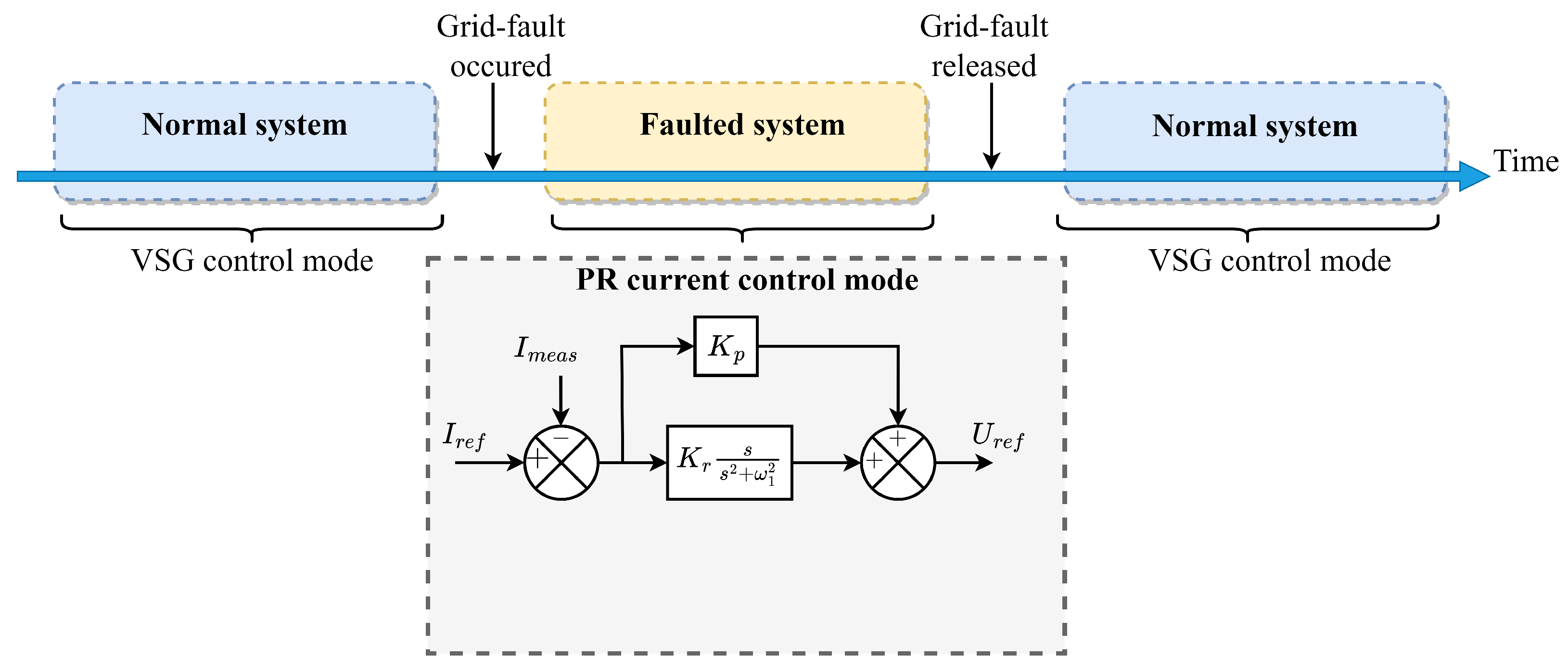
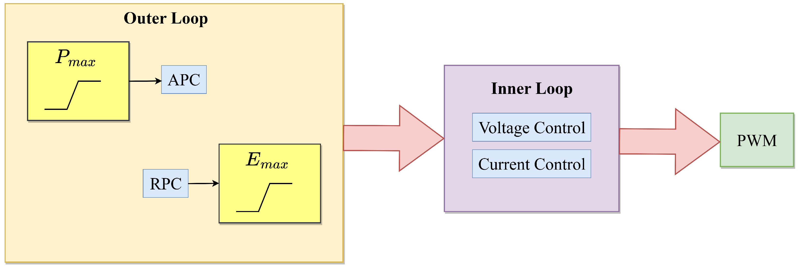
5.2.4. Employing Inverter Current Limits

In G F M inverters, direct control of voltage and frequency is feasible, but the inverter current and fault-ride-through current cannot be limited in transient circumstances. Compared to conventional S G s, which can handle up to seven times their rated current, the P E -based inverters can only hold about 20 percent of the overcurrent during voltage drop events due to the low current rating of switches [91,132]. Therefore, the voltage source features of a G F M inverter require special attention to overcurrent precautions and must be secured against severe defects, such as short circuits, heavy load linkage, line-tripping/reclosing, and voltage phase jumps [133]. Moreover, the transient resilience of the inverter-connected systems must be maintained even after imposing various controls and constraints on the inverter current during significant disturbances.
In [122], a low-voltage ride-through L V R T control technique depending on slick switching was presented to restrict the output current by transforming the voltage source of inverters into the current source mode. This control offers reactive power assistance during grid fault by proportional resonance P R current control, and the phase angle feedback-tracking synchronization method is utilized to permit a smooth transition across modes. With a delay module and no explicit control mechanism, the system can transition back to the grid-connected mode when the fault resolves. The control schematic with a P R regulator control block enclosed diagram is portrayed in Figure 24. The proposed method accelerates the transient process, limits output current, and also offers reactive power assistance during fault conditions.
The transitioning from voltage to current control to set a current limit causes synchronization problems. Consequently, the paper [123] presented a voltage limiter for the G F M inverter that guarantees current limitations remain within safe bounds. The voltage restriction is only specified as a saturation block in the power reference and E M F reference of the G F M inverter, while the remainder of the control remains unchanged from the original controls as shown in Figure 25. To accommodate for a fall in voltage, the reactive power of the inverter should be increased, and the reactive current should be regarded to be at its peak value. The setting of the restriction value relates to the present limit under diverse grid states and code specifications. As a result of the voltage phase’s dependency on the power inverter’s reference, the saturation block similarly restricts the power reference.
In [124], the transient resilience of the G F M inverter relying on unified virtual oscillator control u V O C under symmetrical a c faults was investigated for current-constrained and unconstrained disruptions. This approach creates a current reference within the synchronization loop so that current limiters can be implemented without saturating the outside control loop. When the inverter’s output current surpasses a particular threshold, the controller enters a current-constrained mode, and the size of the current reference is controlled by applying a circular limiter, thereby maintaining the angle. In contrast, the fault current is governed by the G F M nature during the unrestricted mode.
In [125], the influence of the current reference angle on transient resilience was examined while incorporating a current reference saturation technique. Under the saturated state, the critical clearing angle C C A and C C T are computed, as well as the function and duration of the overcurrent required to restore control and maintain system stability. The saturated current angle enhances the system’s C C A and C C T , allowing the system extra time to alleviate the defect and revert to the voltage control mode, boosting the transient stability. Nevertheless, an appropriate angle value is essential to ensure voltage control mode recovery after a malfunction.

5.2.5. Current Limits along with Post-Fault Enhancement Controls

Due to the inappropriate tuning of the controllers, the methods employed to restrict inverter currents during faults may lead to undesirable post-fault transients, including oscillating transients and overshoots. For better system safety, a post-fault recovery mechanism must be provided in addition to inverter current constraints and controls.
In [126], an improved current limiting control mechanism described as a circular limiter was employed to restrict the inverter current references precisely to the appropriate value, in addition to the outside power references alteration, as illustrated in Figure 26. Therefore, the G F M inverter can deliver grid-supporting functionality under typical operational circumstances, and fault ride-through capability is obtained by altering solely the outside power reference generation and not the inner loop structure. The fault-mode signal F M is utilized to transfer the power references from the outer droop controls to the power reference depending on grid regulation specifications.
Moreover, to improve fault retrieval, a dynamic damping controller is developed, which elevates the virtual resistance shortly during fault retrieval to deliver additional damping, as depicted in Figure 27. The primary premise of dynamic damping is to briefly reduce the conductivity of the virtual admittance configuration during the retrieval phase, as shown in the same figure within the box. During a system fault, if the magnitude of the static-reference frame voltage vector falls under a predefined threshold, the fault signal S F is set to high. This triggers the outcome of the SR flip-flop to go high, causing the virtual resistance to increase from R v i r to R v i r ( 1 + x ) at a rate specified by the positive rate limiter P R L . After T d seconds, the resistance recovers to its pre-fault value at a rate defined by the negative rate limiter N R L . The P R L slope increases the likelihood of virtual resistance occurring in a single sample period, whereas the N R L decreases from R v i r ( 1 + x ) to R v i r . The constant x can be manually adjusted in accordance with the amount of virtual damping required for an appropriate fault recovery response.
In [127], the influence of virtual resistance V R in oscillation damping during the fault recovery of a droop-based G F M inverter was examined. In addition to the current saturation employed for overcurrent preservation, the study demonstrated that high virtual resistance might result in a long and complex retrieval methodology or even instability, particularly when the G F M inverter is linked to a rigid grid. Therefore, an adaptive V R   A V R technique is presented based on the rate of power retrieval to tackle the difficulties of fixed-value V R   F V R . The proposed A V R can automatically alter the abundance of virtual resistance so that post-fault fluctuations are adequately dampened without impeding the recovery procedure. The intensity of post-fault oscillations is dictated by the rate of change of the active power, which is assessed by a set of filters such as H P F and L P F , as illustrated in Figure 28. A saturator is inserted to bind the outputs of the L P F s in order to prevent the A V R from deteriorating, and the signals S 0 and S 1 are allocated dependent on whether standard or erroneous states are observed. After assessing the assertiveness of post-fault fluctuations through distinct filters, the A V R can be controlled by K.
The article [128] discussed the post-disturbance synchronization of a V S C depending on droop control and an overcurrent protection implemented by the virtual impedance current restriction technique, which is depicted in Figure 29. During a fault, the inverter’s inner frequency differs, resulting in inverter angle divergence; hence, an adaptive gain comprising droop control can be applied to preserve grid synchronization. The droop gain is calibrated to the magnitudes of the current and voltage to enhance post-disturbance dynamics and transient resilience. This study examines the dynamic behavior and synchronization of the system following a malfunction, regardless of the presence of the inertial influence and virtual impedance.

6. Conclusions

This article provides a comprehensive review of recent publications that explored novel approaches for assessing and enhancing the transient stability of R E S -dominated power systems, as well as a brief description of the power converter topology with a fundamental structure for comprehending the fundamentals. Numerous transient stability analysis tools for R E S -penetrated grids incorporate numerical simulation methods, energy function techniques, and alternative simple and quick graphical methods for analysis. However, the limited thermal capabilities of P E -based inverters require efficient fault-riding through control techniques to minimize the output current during transient disturbances. Furthermore, the design shortcomings of relays and circuit breakers in conventional power systems can be addressed by the inverters’ multi-time scale, programmable, and highly nonlinear control mechanism merged with the enhanced transient stability capabilities of the R E S -penetrated grids. Thus, discussions of recent analysis and enhancement approaches in this review article may pave the way for pioneering solutions to challenges with power systems that employ a substantial proportion of renewable energy. In addition, the effective strategies for strengthening the transient stability of R E S -penetrated grids with multiple V S C / V S I s are the most sought-after research subject for further expansion, and effective system stability analysis must be assured.

Author Contributions

Conceptualization, A.P. and S.K.; methodology, A.P.; writing—original draft preparation, A.P.; writing—review and editing, A.P., S.K.; visualization, A.P.; supervision, S.K.; funding acquisition, S.K. All authors have read and agreed to the published version of the manuscript.

Funding

This research was funded by BK21 Four project funded by the Ministry of Education, Korea (4199990113966), and also by the Korea Institute of Energy Technology Evaluation and Planning (KETEP) and the Ministry of Trade, Industry & Energy (MOTIE) of the Republic of Korea (No. 20224000000150).

Data Availability Statement

No new data were created or analyzed in this study. Data sharing is not applicable to this article.

Acknowledgments

This study was supported by BK21 Four project funded by the Ministry of Education, Korea (4199990113966), and also by the Korea Institute of Energy Technology Evaluation and Planning (KETEP) and the Ministry of Trade, Industry & Energy (MOTIE) of the Republic of Korea (No. 20224000000150).

Conflicts of Interest

The authors declare no conflict of interest.

Abbreviations

The following abbreviations are used in this manuscript:
R E S Renewable Energy Resources
G F L Grid-Following
G F M Grid-Forming
S G Synchronous Generator
P E Power Electronic
V S C Voltage Source Converter
V S I Voltage Source Inverter
V C C Vector Current Control
d q Direct and Quadrature
P L L Phase Locked Loop
M P P T Maximum Power Point Tracking
P C C Point of Common Coupling
A P C Active Power Controller
R P C Reactive Power Controller
E A C Equal Area Criteria
T E F Transient Energy Function
S M I B Single Machine Infinite Bus
L O S Loss of Synchronization
P I Proportional Integral
H P F High Pass Filter
L P F Low Pass Filter
V S G Virtual Synchronous Generator
A V R Automatic Voltage Regulator
R o C o F Rate of Change of Frequency
C C T Critical Clearing Time
C C A Critical Clearing Angle
E M T Electromagnetic Transient
D A E Differential-Algebraic Equation
L V R T Low Voltage Ride Through
T D M Transient Damping Method
P R Proportional Resonance
P R L Positive Rate Limiter
N R L Negative Rate Limiter
V R Virtual Resistance

References

  1. Lin, Y.; Eto, J.H.; Johnson, B.B.; Flicker, J.D.; Lasseter, R.H.; Villegas Pico, H.N.; Seo, G.S.; Pierre, B.J.; Ellis, A. Research Roadmap on Grid-Forming Inverters; Technical Report; National Renewable Energy Lab. (NREL): Golden, CO, USA, 2020. [Google Scholar]
  2. Infield, D.; Freris, L. Renewable Energy in Power Systems; John Wiley & Sons: Hoboken, NJ, USA, 2020. [Google Scholar]
  3. Peng, Q.; Jiang, Q.; Yang, Y.; Liu, T.; Wang, H.; Blaabjerg, F. On the stability of power electronics-dominated systems: Challenges and potential solutions. IEEE Trans. Ind. Appl. 2019, 55, 7657–7670. [Google Scholar] [CrossRef]
  4. Kroposki, B.; Johnson, B.; Zhang, Y.; Gevorgian, V.; Denholm, P.; Hodge, B.M.; Hannegan, B. Achieving a 100% renewable grid: Operating electric power systems with extremely high levels of variable renewable energy. IEEE Power Energy Mag. 2017, 15, 61–73. [Google Scholar] [CrossRef]
  5. Jacobson, M.Z.; Delucchi, M.A.; Bauer, Z.A.; Goodman, S.C.; Chapman, W.E.; Cameron, M.A.; Bozonnat, C.; Chobadi, L.; Clonts, H.A.; Enevoldsen, P.; et al. 100% clean and renewable wind, water, and sunlight all-sector energy roadmaps for 139 countries of the world. Joule 2017, 1, 108–121. [Google Scholar] [CrossRef] [Green Version]
  6. Busarello, L.; Musca, R. Impact of the high share of converter-interfaced generation on electromechanical oscillations in Continental Europe power system. IET Renew. Power Gener. 2020, 14, 3918–3926. [Google Scholar] [CrossRef]
  7. Chen, J.; Liu, M.; Milano, F.; O’Donnell, T. 100% Converter-Interfaced generation using virtual synchronous generator control: A case study based on the irish system. Electr. Power Syst. Res. 2020, 187, 106475. [Google Scholar] [CrossRef]
  8. You, S.; Kou, G.; Liu, Y.; Zhang, X.; Cui, Y.; Till, M.J.; Yao, W.; Liu, Y. Impact of high PV penetration on the inter-area oscillations in the US eastern interconnection. IEEE Access 2017, 5, 4361–4369. [Google Scholar] [CrossRef]
  9. Musca, R.; Gonzalez-Longatt, F.; Gallego Sánchez, C.A. Power System Oscillations with Different Prevalence of Grid-Following and Grid-Forming Converters. Energies 2022, 15, 4273. [Google Scholar] [CrossRef]
  10. Tielens, P.; Van Hertem, D. The relevance of inertia in power systems. Renew. Sustain. Energy Rev. 2016, 55, 999–1009. [Google Scholar] [CrossRef]
  11. Blaabjerg, F.; Yang, Y.; Yang, D.; Wang, X. Distributed power-generation systems and protection. Proc. IEEE 2017, 105, 1311–1331. [Google Scholar] [CrossRef] [Green Version]
  12. Zhong, Q.C. Power-electronics-enabled autonomous power systems: Architecture and technical routes. IEEE Trans. Ind. Electron. 2017, 64, 5907–5918. [Google Scholar] [CrossRef]
  13. Blaabjerg, F.; Liserre, M.; Ma, K. Power electronics converters for wind turbine systems. IEEE Trans. Ind. Appl. 2011, 48, 708–719. [Google Scholar] [CrossRef] [Green Version]
  14. Wang, X.; Blaabjerg, F.; Liserre, M.; Chen, Z.; He, J.; Li, Y. An active damper for stabilizing power-electronics-based AC systems. IEEE Trans. Power Electron. 2013, 29, 3318–3329. [Google Scholar] [CrossRef]
  15. He, J.; Li, Y.W.; Blaabjerg, F.; Wang, X. Active harmonic filtering using current-controlled, grid-connected DG units with closed-loop power control. IEEE Trans. Power Electron. 2013, 29, 642–653. [Google Scholar]
  16. Wang, X.; Li, Y.W.; Blaabjerg, F.; Loh, P.C. Virtual-impedance-based control for voltage-source and current-source converters. IEEE Trans. Power Electron. 2014, 30, 7019–7037. [Google Scholar] [CrossRef]
  17. Harnefors, L.; Wang, X.; Yepes, A.G.; Blaabjerg, F. Passivity-based stability assessment of grid-connected VSCs—An overview. IEEE J. Emerg. Sel. Top. Power Electron. 2015, 4, 116–125. [Google Scholar] [CrossRef] [Green Version]
  18. Kazmierkowski, M.P.; Malesani, L. Current control techniques for three-phase voltage-source PWM converters: A survey. IEEE Trans. Ind. Electron. 1998, 45, 691–703. [Google Scholar] [CrossRef]
  19. Sang, S.; Gao, N.; Cai, X.; Li, R. A novel power-voltage control strategy for the grid-tied inverter to raise the rated power injection level in a weak grid. IEEE J. Emerg. Sel. Top. Power Electron. 2017, 6, 219–232. [Google Scholar] [CrossRef]
  20. Li, Z.; Zang, C.; Zeng, P.; Yu, H.; Li, S.; Bian, J. Control of a Grid-Forming Inverter Based on Sliding-Mode and Mixed {H_2}/{H_∖infty} Control. IEEE Trans. Ind. Electron. 2016, 64, 3862–3872. [Google Scholar] [CrossRef]
  21. Blaabjerg, F.; Teodorescu, R.; Liserre, M.; Timbus, A.V. Overview of control and grid synchronization for distributed power generation systems. IEEE Trans. Ind. Electron. 2006, 53, 1398–1409. [Google Scholar] [CrossRef] [Green Version]
  22. Ali, Z.; Christofides, N.; Hadjidemetriou, L.; Kyriakides, E.; Yang, Y.; Blaabjerg, F. Three-phase phase-locked loop synchronization algorithms for grid-connected renewable energy systems: A review. Renew. Sustain. Energy Rev. 2018, 90, 434–452. [Google Scholar] [CrossRef] [Green Version]
  23. Rocabert, J.; Luna, A.; Blaabjerg, F.; Rodriguez, P. Control of power converters in AC microgrids. IEEE Trans. Power Electron. 2012, 27, 4734–4749. [Google Scholar] [CrossRef]
  24. Wang, X.; Harnefors, L.; Blaabjerg, F. Unified impedance model of grid-connected voltage-source converters. IEEE Trans. Power Electron. 2017, 33, 1775–1787. [Google Scholar] [CrossRef] [Green Version]
  25. Chen, L.; Nian, H.; Lou, B.; Huang, H. Improved control strategy of grid connected inverter without phase locked loop on PCC voltage disturbance. In Proceedings of the 2017 IEEE Energy Conversion Congress and Exposition (ECCE), IEEE, Cincinnati, OH, USA, 1–5 October 2017; pp. 4244–4251. [Google Scholar]
  26. Davari, M.; Mohamed, Y.A.R.I. Robust vector control of a very weak-grid-connected voltage-source converter considering the phase-locked loop dynamics. IEEE Trans. Power Electron. 2016, 32, 977–994. [Google Scholar] [CrossRef]
  27. Dong, D.; Wen, B.; Boroyevich, D.; Mattavelli, P.; Xue, Y. Analysis of phase-locked loop low-frequency stability in three-phase grid-connected power converters considering impedance interactions. IEEE Trans. Ind. Electron. 2014, 62, 310–321. [Google Scholar] [CrossRef]
  28. Rathnayake, D.B.; Akrami, M.; Phurailatpam, C.; Me, S.P.; Hadavi, S.; Jayasinghe, G.; Zabihi, S.; Bahrani, B. Grid forming inverter modeling, control, and applications. IEEE Access 2021, 9, 114781–114807. [Google Scholar] [CrossRef]
  29. Rosso, R.; Wang, X.; Liserre, M.; Lu, X.; Engelken, S. Grid-forming converters: An overview of control approaches and future trends. In Proceedings of the 2020 IEEE Energy Conversion Congress and Exposition (ECCE), IEEE, Detroit, MI, USA, 11–15 October 2020; pp. 4292–4299. [Google Scholar]
  30. Musca, R.; Vasile, A.; Zizzo, G. Grid-forming converters. A critical review of pilot projects and demonstrators. Renew. Sustain. Energy Rev. 2022, 165, 112551. [Google Scholar] [CrossRef]
  31. Meegahapola, L.; Mancarella, P.; Flynn, D.; Moreno, R. Power system stability in the transition to a low carbon grid: A techno-economic perspective on challenges and opportunities. Wiley Interdiscip. Rev. Energy Environ. 2021, 10, e399. [Google Scholar] [CrossRef]
  32. Wang, X.; Taul, M.G.; Wu, H.; Liao, Y.; Blaabjerg, F.; Harnefors, L. Grid-synchronization stability of converter-based resources—An overview. IEEE Open J. Ind. Appl. 2020, 1, 115–134. [Google Scholar] [CrossRef]
  33. Hu, Q.; Han, R.; Quan, X.; Wu, Z.; Tang, C.; Li, W.; Wang, W. Grid-Forming Inverter Enabled Virtual Power Plants with Inertia Support Capability. IEEE Trans. Smart Grid 2022, 13, 4134–4143. [Google Scholar] [CrossRef]
  34. Kkuni, K.V.; Mohan, S.; Yang, G.; Xu, W. Comparative assessment of typical controlrealizations of grid forming converters based ontheir voltage source behaviour. arXiv 2021, arXiv:2106.10048. [Google Scholar]
  35. Roscoe, A.; Brogan, P.; Elliott, D.; Knueppel, T.; Gutierrez, I.; Campion, J.P.; Da Silva, R. Practical experience of operating a grid forming wind park and its response to system events. In Proceedings of the 18th Wind Integration Workshop, Dublin, Ireland, 16–18 October 2019; pp. 16–18. [Google Scholar]
  36. Peacock, B. World’s Largest Grid-Forming Battery to Begin Constructions in Australia. Available online: https://www.pv-magazine.com/2021/08/10/worlds-largest-grid-forming-battery-to-begin-construction-in-australia/ (accessed on 28 November 2022).
  37. Nestor, S. Major Grid-Forming Battery Gains Momentum. Available online: https://www.energymagazine.com.au/major-grid-forming-battery-gains-momentum/ (accessed on 28 November 2022).
  38. Sales. S.A. Grid-Forming Project Setting Worldwide Example. Available online: https://ahlecsolar.com.au/2021/03/12/sa-grid-forming-project-setting-worldwide-example/ (accessed on 28 November 2022).
  39. Hu, J.; Chi, Y.; Tian, X.; Zhou, Y.; He, W. A coordinated and steadily fault ride through strategy under short-circuit fault of the wind power grid connected system based on the grid-forming control. Energy Rep. 2022, 8, 333–341. [Google Scholar] [CrossRef]
  40. Aragon, D.; Unamuno, E.; Ceballos, S.; Barrena, J. Comparative small-signal evaluation of advanced grid-forming control techniques. Electr. Power Syst. Res. 2022, 211, 108154. [Google Scholar] [CrossRef]
  41. Ojo, Y.; Benmiloud, M.; Lestas, I. Frequency and voltage control schemes for three-phase grid-forming inverters. IFAC-PapersOnLine 2020, 53, 13471–13476. [Google Scholar] [CrossRef]
  42. Tayyebi, A.; Groß, D.; Anta, A.; Kupzog, F.; Dörfler, F. Frequency stability of synchronous machines and grid-forming power converters. IEEE J. Emerg. Sel. Top. Power Electron. 2020, 8, 1004–1018. [Google Scholar] [CrossRef] [Green Version]
  43. Shakerighadi, B.; Johansson, N.; Eriksson, R.; Mitra, P.; Bolzoni, A.; Clark, A.; Nee, H.P. An overview of stability challenges for power-electronic-dominated power systems: The grid-forming approach. IET Gener. Transm. Distrib. 2022, 17, 284–306. [Google Scholar] [CrossRef]
  44. Sauer, P.W.; Pai, M.A.; Chow, J.H. Power System Dynamics and Stability: With Synchrophasor Measurement and Power System Toolbox; John Wiley & Sons: Hoboken, NJ, USA, 2017. [Google Scholar]
  45. Xiong, L.; Zhuo, F.; Wang, F.; Liu, X.; Chen, Y.; Zhu, M.; Yi, H. Static synchronous generator model: A new perspective to investigate dynamic characteristics and stability issues of grid-tied PWM inverter. IEEE Trans. Power Electron. 2015, 31, 6264–6280. [Google Scholar] [CrossRef]
  46. Taul, M.G.; Wang, X.; Davari, P.; Blaabjerg, F. An overview of assessment methods for synchronization stability of grid-connected converters under severe symmetrical grid faults. IEEE Trans. Power Electron. 2019, 34, 9655–9670. [Google Scholar] [CrossRef] [Green Version]
  47. Xiong, L.; Liu, X.; Liu, Y.; Zhuo, F. Modeling and stability issues of voltage-source converter dominated power systems: A review. CSEE J. Power Energy Syst. 2020, 8, 1530–1549. [Google Scholar]
  48. Shuai, Z.; Shen, C.; Yin, X.; Liu, X.; Shen, Z.J. Fault analysis of inverter-interfaced distributed generators with different control schemes. IEEE Trans. Power Deliv. 2017, 33, 1223–1235. [Google Scholar] [CrossRef]
  49. He, J.; Li, Y.W. Analysis, design, and implementation of virtual impedance for power electronics interfaced distributed generation. IEEE Trans. Ind. Appl. 2011, 47, 2525–2538. [Google Scholar] [CrossRef]
  50. Paquette, A.D.; Divan, D.M. Virtual impedance current limiting for inverters in microgrids with synchronous generators. IEEE Trans. Ind. Appl. 2014, 51, 1630–1638. [Google Scholar] [CrossRef]
  51. Pan, D.; Ruan, X.; Wang, X.; Yu, H.; Xing, Z. Analysis and design of current control schemes for LCL-type grid-connected inverter based on a general mathematical model. IEEE Trans. Power Electron. 2016, 32, 4395–4410. [Google Scholar] [CrossRef]
  52. Mirafzal, B.; Adib, A. On grid-interactive smart inverters: Features and advancements. IEEE Access 2020, 8, 160526–160536. [Google Scholar] [CrossRef]
  53. Unruh, P.; Nuschke, M.; Strauß, P.; Welck, F. Overview on grid-forming inverter control methods. Energies 2020, 13, 2589. [Google Scholar] [CrossRef]
  54. Pattabiraman, D.; Lasseter, R.; Jahns, T. Comparison of grid following and grid forming control for a high inverter penetration power system. In Proceedings of the 2018 IEEE Power & Energy Society General Meeting (PESGM), IEEE, Portland, OR, USA, 5–10 August 2018; pp. 1–5. [Google Scholar]
  55. Matevosyan, J.; Badrzadeh, B.; Prevost, T.; Quitmann, E.; Ramasubramanian, D.; Urdal, H.; Achilles, S.; MacDowell, J.; Huang, S.H.; Vital, V.; et al. Grid-forming inverters: Are they the key for high renewable penetration? IEEE Power Energy Mag. 2019, 17, 89–98. [Google Scholar] [CrossRef]
  56. Anttila, S.; Döhler, J.S.; Oliveira, J.G.; Boström, C. Grid Forming Inverters: A Review of the State of the Art of Key Elements for Microgrid Operation. Energies 2022, 15, 5517. [Google Scholar] [CrossRef]
  57. Khan, S.A.; Wang, M.; Su, W.; Liu, G.; Chaturvedi, S. Grid-Forming Converters for Stability Issues in Future Power Grids. Energies 2022, 15, 4937. [Google Scholar] [CrossRef]
  58. Rosso, R.; Wang, X.; Liserre, M.; Lu, X.; Engelken, S. Grid-forming converters: Control approaches, grid-synchronization, and future trends—A review. IEEE Open J. Ind. Appl. 2021, 2, 93–109. [Google Scholar] [CrossRef]
  59. Hossain, M.A.; Pota, H.R.; Issa, W.; Hossain, M.J. Overview of AC microgrid controls with inverter-interfaced generations. Energies 2017, 10, 1300. [Google Scholar] [CrossRef]
  60. Milano, F.; Dörfler, F.; Hug, G.; Hill, D.J.; Verbič, G. Foundations and challenges of low-inertia systems. In Proceedings of the 2018 Power Systems Computation Conference (PSCC), IEEE, Dublin, Ireland, 11–15 June 2018; pp. 1–25. [Google Scholar]
  61. Bevrani, H.; Ise, T.; Miura, Y. Virtual synchronous generators: A survey and new perspectives. Int. J. Electr. Power Energy Syst. 2014, 54, 244–254. [Google Scholar] [CrossRef]
  62. Tamrakar, U.; Shrestha, D.; Maharjan, M.; Bhattarai, B.P.; Hansen, T.M.; Tonkoski, R. Virtual inertia: Current trends and future directions. Appl. Sci. 2017, 7, 654. [Google Scholar] [CrossRef] [Green Version]
  63. Zhu, S.; Liu, K.; Le, J.; Ji, K.; Huai, Q.; Wang, F.; Liao, X. Stability assessment of modular multilevel converters based on linear time-periodic theory: Time-domain vs. frequency-domain. IEEE Trans. Power Deliv. 2022, 37, 3980–3995. [Google Scholar] [CrossRef]
  64. Tzounas, G.; Dassios, I.; Milano, F. Small-signal stability analysis of numerical integration methods. IEEE Trans. Power Syst. 2022, 37, 4796–4806. [Google Scholar] [CrossRef]
  65. Chow, J.H.; Sanchez-Gasca, J.J. Power System Modeling, Computation, and Control; John Wiley & Sons: Hoboken, NJ, USA, 2020. [Google Scholar]
  66. Poulose, A.; Kim, S. Synchronizing Torque-Based Transient Stability Index of a Multimachine Interconnected Power System. Energies 2022, 15, 3432. [Google Scholar] [CrossRef]
  67. Chang, Y.; Hu, J.; Yuan, X. Mechanism analysis of DFIG-based wind turbine’s fault current during LVRT with equivalent inductances. IEEE J. Emerg. Sel. Top. Power Electron. 2019, 8, 1515–1527. [Google Scholar] [CrossRef]
  68. Alaboudy, A.K.; Zeineldin, H.H.; Kirtley, J. Microgrid stability characterization subsequent to fault-triggered islanding incidents. IEEE Trans. Power Deliv. 2012, 27, 658–669. [Google Scholar] [CrossRef]
  69. Weise, B. Impact of K-factor and active current reduction during fault-ride-through of generating units connected via voltage-sourced converters on power system stability. IET Renew. Power Gener. 2015, 9, 25–36. [Google Scholar] [CrossRef]
  70. Alipoor, J.; Miura, Y.; Ise, T. Stability assessment and optimization methods for microgrid with multiple VSG units. IEEE Trans. Smart Grid 2016, 9, 1462–1471. [Google Scholar] [CrossRef]
  71. Yang, D.; Wang, X. Unified modular state-space modeling of grid-connected voltage-source converters. IEEE Trans. Power Electron. 2020, 35, 9700–9715. [Google Scholar] [CrossRef]
  72. Zhang, P.; Martí, J.R.; Dommel, H.W. Shifted-frequency analysis for EMTP simulation of power-system dynamics. IEEE Trans. Circuits Syst. I Regul. Pap. 2010, 57, 2564–2574. [Google Scholar] [CrossRef] [Green Version]
  73. Qi, L.; Woodruff, S. Stability analysis and assessment of integrated power systems using RTDS. In Proceedings of the IEEE Electric Ship Technologies Symposium, 2005, IEEE, Philadelphia, PA, USA, 25–27 July; 2005; pp. 325–332. [Google Scholar]
  74. Shair, J.; Xie, X.; Liu, W.; Li, X.; Li, H. Modeling and stability analysis methods for investigating subsynchronous control interaction in large-scale wind power systems. Renew. Sustain. Energy Rev. 2021, 135, 110420. [Google Scholar] [CrossRef]
  75. Li, Y.; Shu, D.; Shi, F.; Yan, Z.; Zhu, Y.; Tai, N. A multi-rate co-simulation of combined phasor-domain and time-domain models for large-scale wind farms. IEEE Trans. Energy Convers. 2019, 35, 324–335. [Google Scholar] [CrossRef]
  76. Ye, X.; Tang, Y.; Shu, D. Large step size electromagnetic transient simulations by matrix transformation-based shifted-frequency phasor models. IET Gener. Transm. Distrib. 2020, 14, 2890–2900. [Google Scholar] [CrossRef]
  77. Li, Y.; Shu, D.; Hu, J.; Yan, Z.; Zhou, Y.; Wang, H. A multi-area Thevenin equivalent based multi-rate co-simulation for control design of practical LCC HVDC system. Int. J. Electr. Power Energy Syst. 2020, 115, 105479. [Google Scholar] [CrossRef]
  78. Jeon, J.H.; Kim, J.Y.; Kim, H.M.; Kim, S.K.; Cho, C.; Kim, J.M.; Ahn, J.B.; Nam, K.Y. Development of hardware in-the-loop simulation system for testing operation and control functions of microgrid. IEEE Trans. Power Electron. 2010, 25, 2919–2929. [Google Scholar] [CrossRef]
  79. Topcu, U.; Packard, A.; Seiler, P.; Wheeler, T. Stability region analysis using simulations and sum-of-squares programming. In Proceedings of the 2007 American Control Conference, IEEE, New York, NY, USA, 9–13 July 2007; pp. 6009–6014. [Google Scholar]
  80. Shuai, Z.; Shen, C.; Liu, X.; Li, Z.; Shen, Z.J. Transient angle stability of virtual synchronous generators using Lyapunov’s direct method. IEEE Trans. Smart Grid 2018, 10, 4648–4661. [Google Scholar] [CrossRef]
  81. Kabalan, M.; Singh, P.; Niebur, D. A design and optimization tool for inverter-based microgrids using large-signal nonlinear analysis. IEEE Trans. Smart Grid 2018, 10, 4566–4576. [Google Scholar] [CrossRef]
  82. Odun-Ayo, T.; Crow, M.L. Structure-preserved power system transient stability using stochastic energy functions. IEEE Trans. Power Syst. 2012, 27, 1450–1458. [Google Scholar] [CrossRef]
  83. Demenkov, M. A Matlab tool for regions of attraction estimation via numerical algebraic geometry. In Proceedings of the 2015 International Conference on Mechanics-Seventh Polyakhov’s Reading, IEEE, St. Petersburg, FL, USA, 2–6 February 2015; pp. 1–5. [Google Scholar]
  84. Fu, X.; Sun, J.; Huang, M.; Tian, Z.; Yan, H.; Iu, H.H.C.; Hu, P.; Zha, X. Large-signal stability of grid-forming and grid-following controls in voltage source converter: A comparative study. IEEE Trans. Power Electron. 2020, 36, 7832–7840. [Google Scholar] [CrossRef]
  85. Hart, P.; Lesieutre, B. Energy function for a grid-tied, droop-controlled inverter. In Proceedings of the 2014 North American Power Symposium (NAPS), IEEE, Pullman, WA, USA, 7–9 September 2014; pp. 1–6. [Google Scholar]
  86. Tang, W.; Hu, J.; Chang, Y.; Liu, F. Modeling of DFIG-based wind turbine for power system transient response analysis in rotor speed control timescale. IEEE Trans. Power Syst. 2018, 33, 6795–6805. [Google Scholar] [CrossRef]
  87. Cheng, H.; Shuai, Z.; Shen, C.; Liu, X.; Li, Z.; Shen, Z.J. Transient angle stability of paralleled synchronous and virtual synchronous generators in islanded microgrids. IEEE Trans. Power Electron. 2020, 35, 8751–8765. [Google Scholar] [CrossRef]
  88. Yuan, H.; Xin, H.; Huang, L.; Wang, Z.; Wu, D. Stability analysis and enhancement of type-4 wind turbines connected to very weak grids under severe voltage sags. IEEE Trans. Energy Convers. 2018, 34, 838–848. [Google Scholar]
  89. Bretas, N.G.; Alberto, L.F. Lyapunov function for power systems with transfer conductances: Extension of the invariance principle. IEEE Trans. Power Syst. 2003, 18, 769–777. [Google Scholar] [CrossRef]
  90. Ma, S.; Geng, H.; Liu, L.; Yang, G.; Pal, B.C. Grid-synchronization stability improvement of large scale wind farm during severe grid fault. IEEE Trans. Power Syst. 2017, 33, 216–226. [Google Scholar] [CrossRef] [Green Version]
  91. Huang, L.; Xin, H.; Wang, Z.; Zhang, L.; Wu, K.; Hu, J. Transient stability analysis and control design of droop-controlled voltage source converters considering current limitation. IEEE Trans. Smart Grid 2017, 10, 578–591. [Google Scholar] [CrossRef]
  92. Wu, H.; Wang, X. Design-oriented transient stability analysis of PLL-synchronized voltage-source converters. IEEE Trans. Power Electron. 2019, 35, 3573–3589. [Google Scholar] [CrossRef] [Green Version]
  93. Pan, D.; Wang, X.; Liu, F.; Shi, R. Transient stability of voltage-source converters with grid-forming control: A design-oriented study. IEEE J. Emerg. Sel. Top. Power Electron. 2020, 8, 1019–1033. [Google Scholar] [CrossRef]
  94. Naderi, M.; Khayat, Y.; Shafiee, Q.; Dragicevic, T.; Bevrani, H.; Blaabjerg, F. Interconnected autonomous AC microgrids via back-to-back converters—Part I: Small-signal modeling. IEEE Trans. Power Electron. 2019, 35, 4728–4740. [Google Scholar] [CrossRef]
  95. Strogatz, S.H. Nonlinear Dynamics and Chaos: With Applications to Physics, Biology, Chemistry, and Engineering; CRC Press: Boca Raton, FL, USA, 2018. [Google Scholar]
  96. Xin, H.; Huang, L.; Zhang, L.; Wang, Z.; Hu, J. Synchronous instability mechanism of Pf droop-controlled voltage source converter caused by current saturation. IEEE Trans. Power Syst. 2016, 31, 5206–5207. [Google Scholar] [CrossRef]
  97. Wu, H.; Wang, X. Design-oriented transient stability analysis of grid-connected converters with power synchronization control. IEEE Trans. Ind. Electron. 2018, 66, 6473–6482. [Google Scholar] [CrossRef] [Green Version]
  98. Hu, J.; Yuan, H.; Yuan, X. Modeling of DFIG-based WTs for small-signal stability analysis in DVC timescale in power electronized power systems. IEEE Trans. Energy Convers. 2017, 32, 1151–1165. [Google Scholar] [CrossRef]
  99. Pei, J.; Yao, J.; Liu, R.; Zeng, D.; Sun, P.; Zhang, H.; Liu, Y. Characteristic analysis and risk assessment for voltage–frequency coupled transient instability of large-scale grid-connected renewable energy plants during LVRT. IEEE Trans. Ind. Electron. 2019, 67, 5515–5530. [Google Scholar] [CrossRef]
  100. Hornik, T.; Zhong, Q.C. Control of Power Inverters in Renewable Energy and Smart Grid Integration; John Wiley & Sons: Hoboken, NJ, USA, 2012. [Google Scholar]
  101. Kundur, P.S.; Malik, O.P. Power System Stability and Control; McGraw-Hill Education: New York, NY, USA, 2022. [Google Scholar]
  102. Wang, X.; Blaabjerg, F. Harmonic stability in power electronic-based power systems: Concept, modeling, and analysis. IEEE Trans. Smart Grid 2018, 10, 2858–2870. [Google Scholar] [CrossRef] [Green Version]
  103. Erlich, I.; Shewarega, F.; Engelhardt, S.; Kretschmann, J.; Fortmann, J.; Koch, F. Effect of wind turbine output current during faults on grid voltage and the transient stability of wind parks. In Proceedings of the 2009 IEEE Power & Energy Society General Meeting, IEEE, Calgary, AB, Canada, 26–30 July 2009; pp. 1–8. [Google Scholar]
  104. Shewarega, F.; Erlich, I.; Rueda, J.L. Impact of large offshore wind farms on power system transient stability. In Proceedings of the 2009 IEEE/PES Power Systems Conference and Exposition, IEEE, Seattle, WA, USA, 15–18 March 2009; pp. 1–8. [Google Scholar]
  105. Göksu, Ö.; Teodorescu, R.; Bak, C.L.; Iov, F.; Kjær, P.C. Instability of wind turbine converters during current injection to low voltage grid faults and PLL frequency based stability solution. IEEE Trans. Power Syst. 2014, 29, 1683–1691. [Google Scholar] [CrossRef]
  106. Geng, H.; Liu, L.; Li, R. Synchronization and reactive current support of PMSG-based wind farm during severe grid fault. IEEE Trans. Sustain. Energy 2018, 9, 1596–1604. [Google Scholar] [CrossRef]
  107. Betz, R.E.; Taul, M.G. Identification of grid impedance during severe faults. In Proceedings of the 2019 IEEE Energy Conversion Congress and Exposition (ECCE), IEEE, Baltimore, MD, USA, 29 September–3 October 2019; pp. 1076–1082. [Google Scholar]
  108. He, X.; Geng, H.; Li, R.; Pal, B.C. Transient stability analysis and enhancement of renewable energy conversion system during LVRT. IEEE Trans. Sustain. Energy 2019, 11, 1612–1623. [Google Scholar] [CrossRef]
  109. Taul, M.G.; Wang, X.; Davari, P.; Blaabjerg, F. Robust fault ride through of converter-based generation during severe faults with phase jumps. IEEE Trans. Ind. Appl. 2019, 56, 570–583. [Google Scholar] [CrossRef]
  110. Wu, H.; Wang, X. Transient stability impact of the phase-locked loop on grid-connected voltage source converters. In Proceedings of the 2018 International Power Electronics Conference (IPEC-Niigata 2018-ECCE Asia), IEEE, Niigata, Japan, 20–24 May 2018; pp. 2673–2680. [Google Scholar]
  111. Taul, M.G.; Wang, X.; Davari, P.; Blaabjerg, F. Systematic approach for transient stability evaluation of grid-tied converters during power system faults. In Proceedings of the 2019 IEEE Energy Conversion Congress and Exposition (ECCE), IEEE, Baltimore, MD, USA, 29 September–3 October 2019; pp. 5191–5198. [Google Scholar]
  112. Wu, H.; Wang, X. An adaptive phase-locked loop for the transient stability enhancement of grid-connected voltage source converters. In Proceedings of the 2018 IEEE Energy Conversion Congress and Exposition (ECCE), IEEE, Portland, OR, USA, 23–27 September 2018; pp. 5892–5898. [Google Scholar]
  113. Diedrichs, V.; Beekmann, A.; Adloff, S. Loss of (Angle) Stability of Wind Power Plants. The Underestimated Phenomenon in Case of Very Low Short Circuit Ratio. 2011. Available online: https://www.osti.gov/etdeweb/biblio/21594671 (accessed on 28 November 2022).
  114. Pan, D.; Wang, X.; Liu, F.; Shi, R. Transient stability impact of reactive power control on grid-connected converters. In Proceedings of the 2019 IEEE Energy Conversion Congress and Exposition (ECCE), IEEE, Baltimore, MD, USA, 29 September–3 October 2019; pp. 4311–4316. [Google Scholar]
  115. Wu, H.; Wang, X. A mode-adaptive power-angle control method for transient stability enhancement of virtual synchronous generators. IEEE J. Emerg. Sel. Top. Power Electron. 2020, 8, 1034–1049. [Google Scholar] [CrossRef]
  116. Chen, M.; Zhou, D.; Blaabjerg, F. Enhanced transient angle stability control of grid-forming converter based on virtual synchronous generator. IEEE Trans. Ind. Electron. 2021, 69, 9133–9144. [Google Scholar] [CrossRef]
  117. Alipoor, J.; Miura, Y.; Ise, T. Power system stabilization using virtual synchronous generator with alternating moment of inertia. IEEE J. Emerg. Sel. Top. Power Electron. 2015, 3, 451–458. [Google Scholar] [CrossRef]
  118. Li, D.; Zhu, Q.; Lin, S.; Bian, X. A self-adaptive inertia and damping combination control of VSG to support frequency stability. IEEE Trans. Energy Convers. 2016, 32, 397–398. [Google Scholar] [CrossRef]
  119. Ebrahimi, M.; Khajehoddin, S.A.; Karimi-Ghartemani, M. An improved damping method for virtual synchronous machines. IEEE Trans. Sustain. Energy 2019, 10, 1491–1500. [Google Scholar] [CrossRef]
  120. Xiong, X.; Wu, C.; Hu, B.; Pan, D.; Blaabjerg, F. Transient damping method for improving the synchronization stability of virtual synchronous generators. IEEE Trans. Power Electron. 2020, 36, 7820–7831. [Google Scholar] [CrossRef]
  121. Xiong, X.; Wu, C.; Cheng, P.; Blaabjerg, F. An optimal damping design of virtual synchronous generators for transient stability enhancement. IEEE Trans. Power Electron. 2021, 36, 11026–11030. [Google Scholar] [CrossRef]
  122. Shi, K.; Song, W.; Xu, P.; Liu, R.; Fang, Z.; Ji, Y. Low-voltage ride-through control strategy for a virtual synchronous generator based on smooth switching. IEEE Access 2017, 6, 2703–2711. [Google Scholar] [CrossRef]
  123. Chen, J.; Prystupczuk, F.; O’Donnell, T. Use of voltage limits for current limitations in grid-forming converters. CSEE J. Power Energy Syst. 2020, 6, 259–269. [Google Scholar]
  124. Awal, M.; Husain, I. Transient Stability Assessment for Current-Constrained and Current-Unconstrained Fault Ride Through in Virtual Oscillator-Controlled Converters. IEEE J. Emerg. Sel. Top. Power Electron. 2021, 9, 6935–6946. [Google Scholar] [CrossRef]
  125. Rokrok, E.; Qoria, T.; Bruyere, A.; Francois, B.; Guillaud, X. Transient stability assessment and enhancement of grid-forming converters embedding current reference saturation as current limiting strategy. IEEE Trans. Power Syst. 2021, 37, 1519–1531. [Google Scholar] [CrossRef]
  126. Taul, M.G.; Wang, X.; Davari, P.; Blaabjerg, F. Current limiting control with enhanced dynamics of grid-forming converters during fault conditions. IEEE J. Emerg. Sel. Top. Power Electron. 2019, 8, 1062–1073. [Google Scholar] [CrossRef] [Green Version]
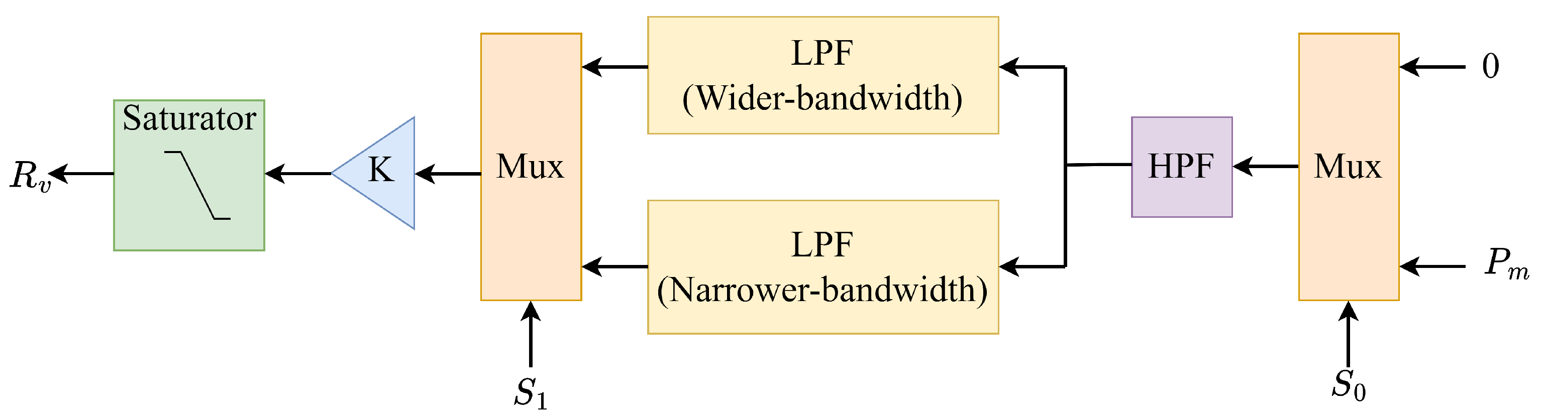
  127. Me, S.P.; Zabihi, S.; Blaabjerg, F.; Bahrani, B. Adaptive Virtual Resistance for Postfault Oscillation Damping in Grid-Forming Inverters. IEEE Trans. Power Electron. 2021, 37, 3813–3824. [Google Scholar] [CrossRef]
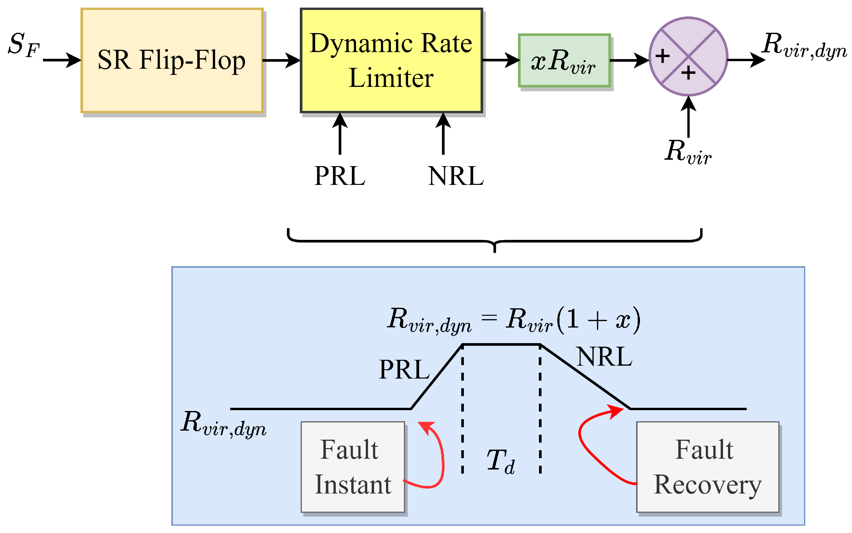
  128. Qoria, T.; Gruson, F.; Colas, F.; Denis, G.; Prevost, T.; Guillaud, X. Critical clearing time determination and enhancement of grid-forming converters embedding virtual impedance as current limitation algorithm. IEEE J. Emerg. Sel. Top. Power Electron. 2019, 8, 1050–1061. [Google Scholar] [CrossRef] [Green Version]
  129. Li, Y.W.; Kao, C.N. An accurate power control strategy for power-electronics-interfaced distributed generation units operating in a low-voltage multibus microgrid. IEEE Trans. Power Electron. 2009, 24, 2977–2988. [Google Scholar]
  130. Fang, J.; Li, H.; Tang, Y.; Blaabjerg, F. Distributed power system virtual inertia implemented by grid-connected power converters. IEEE Trans. Power Electron. 2017, 33, 8488–8499. [Google Scholar] [CrossRef] [Green Version]
  131. Fang, J.; Li, H.; Tang, Y.; Blaabjerg, F. On the inertia of future more-electronics power systems. IEEE J. Emerg. Sel. Top. Power Electron. 2018, 7, 2130–2146. [Google Scholar] [CrossRef]
  132. Denis, G.; Prevost, T.; Debry, M.S.; Xavier, F.; Guillaud, X.; Menze, A. The Migrate project: The challenges of operating a transmission grid with only inverter-based generation. A grid-forming control improvement with transient current-limiting control. IET Renew. Power Gener. 2018, 12, 523–529. [Google Scholar] [CrossRef]
  133. Sadeghkhani, I.; Golshan, M.E.H.; Guerrero, J.M.; Mehrizi-Sani, A. A current limiting strategy to improve fault ride-through of inverter interfaced autonomous microgrids. IEEE Trans. Smart Grid 2016, 8, 2138–2148. [Google Scholar] [CrossRef] [Green Version]
Figure 1. Distinguishing characteristics of G F L and G F M .
Energies 16 02495 g001
Figure 2. Control approximations of G F L .
Energies 16 02495 g002
Figure 3. Control approximations of G F M .
Energies 16 02495 g003
Figure 4. Generalized control structure of V S C / V S I topologies.
Energies 16 02495 g004
Figure 5. Control techniques for outer and inner control loops [59].
Energies 16 02495 g005
Figure 6. Concept of Virtual Inertia [62].
Energies 16 02495 g006
Figure 7. Virtual inertia implementation topologies [62].
Energies 16 02495 g007
Figure 8. Transient stability analysis methods.
Energies 16 02495 g008
Figure 9. Control configuration for a voltage-dependent active current deduction [103,104].
Energies 16 02495 g009
Figure 10. P L L frequency-dependent active current injection (solid block) [105] and active power injection (dashed block) [106].
Energies 16 02495 g010
Figure 11. Current vector alignment for a stable operating area [90].
Energies 16 02495 g011
Figure 12. EAC damping provision and revocation of accelerating and decelerating areas [108].
Energies 16 02495 g012
Figure 13. General control diagram of P L L .
Energies 16 02495 g013
Figure 14. Approach 1 [69,109].
Energies 16 02495 g014
Figure 15. Approach 2 [110,111].
Energies 16 02495 g015
Figure 16. Approach 3 [112].
Energies 16 02495 g016
Figure 17. Approach 4 [92,110].
Energies 16 02495 g017
Figure 18. Reducing active power references [80,87].
Energies 16 02495 g018
Figure 19. Increasing reactive power reference [114].
Energies 16 02495 g019
Figure 20. Mode-adaptive control [115].
Energies 16 02495 g020
Figure 21. V S G ’s enhanced transient angle stability control approach [116].
Energies 16 02495 g021
Figure 22. Proposed transient damping on the A P C loop [120].
Energies 16 02495 g022
Figure 23. Proposed T D M through H P F [121].
Energies 16 02495 g023
Figure 24. Control schematic diagram and PR regulator control block diagram [122].
Energies 16 02495 g024
Figure 25. Voltage limiter for the G F M inverter [123].
Energies 16 02495 g025
Figure 26. Proposed fault-mode control structure [126] (* indicated the reference values).
Energies 16 02495 g026
Figure 27. Dynamic damping during fault recovery [126].
Energies 16 02495 g027
Figure 28. Adaptive virtual resistance operation [127].
Energies 16 02495 g028
Figure 29. Grid-forming control structure in [128].
Energies 16 02495 g029
Table 1. Transient stability enhancement techniques for G F L systems.
CategoryEnhancement Technique
Modify active current or powerDuring fault, reduce active current proportional to voltage drop [103,104]
Raise active current reference in accordance with P L L frequency error [105]
Raise active power baseline according to P L L  [106]
Align vector current angle with vector line impedance angle [107]
Eliminate the accelerating and decelerating areas in E A C by setting reference power equal to actual power [108]
Modify synchronization loop (means P L L )Freeze P L L during fault [69,109]
Increase damping ratio of P L L [110,111]
Adaptive decrease integral gain during fault [112]
During fault, transform P L L to a first-order system [92,110]
Table 2. Transient stability enhancement techniques for G F M systems.
CategoryEnhancement Technique
Modify active and reactive power referenceReducing active power reference [80,87]
Increase reactive power reference [114]
Modify control loopsMode-adaptive control [115]
Internal voltage regulation control [116]
Modify moment of inertia and damping parametersAlternating inertia [117]
Distinct quantities of virtual inertia [118]
Design guidelines that can enhance the system’s damping and transient stability [93]
Complex damping solutions to avoid steady-state characteristics change [119]
Enhance synchronization stability and frequency stability simultaneously [120]
Adding frequency component to power reference through a H P F [121]
Employing inverter current limitsSwitching to a G F L converter [122]
Limiting converter output voltage by current limitation [123]
Employing circular current restriction in unified virtual oscillator regulation [124]
Account the effect of current reference angle [125]
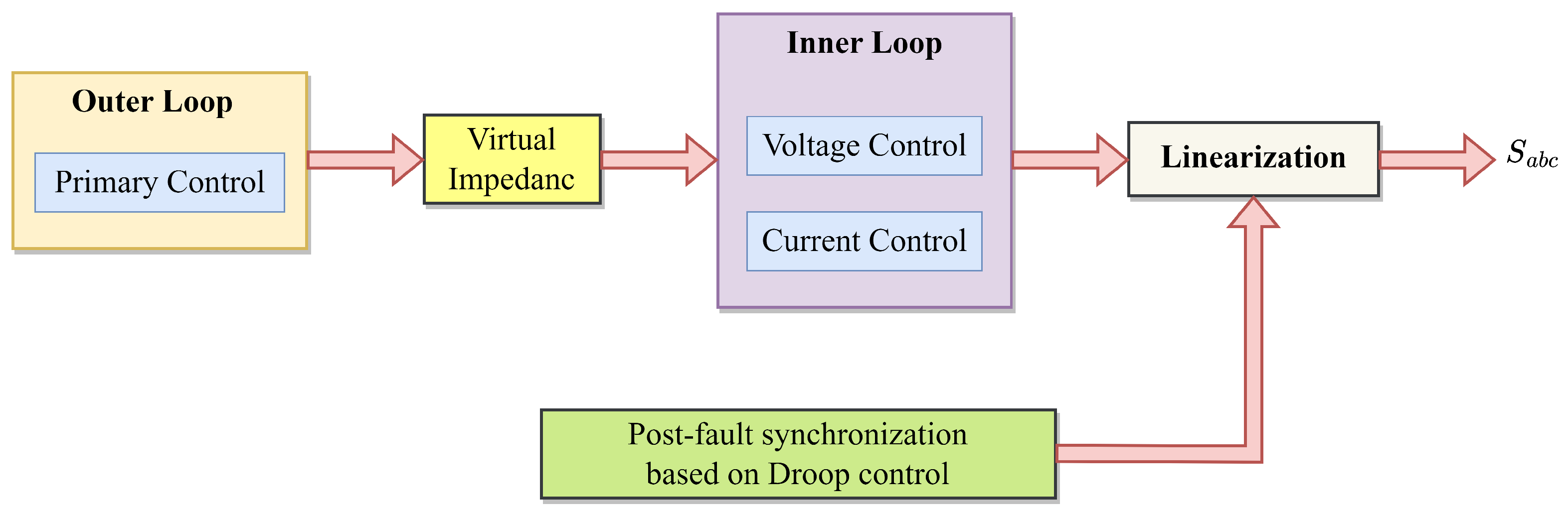
Current limits along with post-fault enhancement controlsModifying power references in accordance with the voltage drop and a virtual resistance [126]
Utilizing virtual resistance that is adjustable dependent on the amplitude of post-disturbance fluctuations [127]
Utilize virtual impedance and adjustable controller variables [128]
Disclaimer/Publisher’s Note: The statements, opinions and data contained in all publications are solely those of the individual author(s) and contributor(s) and not of MDPI and/or the editor(s). MDPI and/or the editor(s) disclaim responsibility for any injury to people or property resulting from any ideas, methods, instructions or products referred to in the content.

